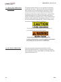
1
Henny Penny
Evolution Elite™
Reduced Oil Capacity Open Fryers
(Split Vat & Full Vat– Electric)
Model EEE-141
Model EEE-142
Model EEE-143
Model EEE-144
OPERATOR’S MANUAL
REGISTER WARRANTY ONLINE AT WWW.HENNYPENNY.COM
LIMITED WARRANTY FOR HENNY PENNY EQUIPMENT
Subject to the following conditions, Henny Penny Corporation makes the following limited warranties to the original
purchaser only for Henny Penny appliances and replacement parts:
NEW EQUIPMENT: Any part of a new appliance, except baskets, lamps, and fuses, which proves to be defective in
material or workmanship within two (2) years from date of original installation, will be repaired or replaced without
charge F.O.B. factory, Eaton, Ohio, or F.O.B. authorized distributor. Baskets will be repaired or replaced for ninety (90)
days from date of original installation. Lamps and fuses are not covered under this Limited Warranty. To validate this
warranty, the registration card for the appliance must be mailed to Henny Penny within ten (10) days after installation.
FILTER SYSTEM: Failure of any parts within a fryer filter system caused by the use of the non-OEM filters or
other unapproved filters is not covered under this Limited Warranty.
REPLACEMENT PARTS: Any appliance replacement part, except lamps and fuses, which proves to be defective in
material or workmanship within ninety (90) days from date of original installation will be repaired or replaced without
charge F.O.B. factory, Eaton, Ohio, or F.O.B. authorized distributor.
The warranty for new equipment covers the repair or replacement of the defective part and includes labor charges and
maximum mileage charges of 200 miles round trip for a period of one (1) year from the date of original installation.
The warranty for replacement parts covers only the repair or replacement of the defective part and does not include any
labor charges for the removal and installation of any parts, travel, or other expenses incidental to the repair or replacement of
a part.
EXTENDED FRYPOT WARRANTY: Henny Penny will replace any frypot that fails due to manufacturing or workmanship
issues for a period of up to seven (7) years from date of manufacture. This warranty shall not cover any frypot that fails due to
any misuse or abuse, such as heating of the frypot without shortening.
0 TO 3 YEARS:
During this time, any frypot that fails due to manufacturing or workmanship issues will
be replaced at no charge for parts, labor, or freight. Henny Penny will either install a new frypot at no cost or
provide a new or reconditioned replacement fryer at no cost.
3 TO 7 YEARS:
During this time, any frypot that fails due to manufacturing or workmanship issues will
be replaced at no charge for the frypot only. Any freight charges and labor costs to install the new frypot as
well as the cost of any other parts replaced, such as insulation, thermal sensors, high limits, fittings, and
hardware, will be the responsibility of the owner.
Any claim must be presented to either Henny Penny or the distributor from whom the appliance was purchased. No
allowance will be granted for repairs made by anyone else without Henny Penny’s written consent. If damage occurs during
shipping, notify the sender at once so that a claim may be filed.
THE ABOVE LIMITED WARRANTY SETS FORTH THE SOLE REMEDY AGAINST HENNY PENNY FOR ANY BREACH
OF WARRANTY OR OTHER TERM. BUYER AGREES THAT NO OTHER REMEDY (INCLUDING CLAIMS FOR ANY INCIDENTAL OR CONSEQUENTIAL DAMAGES) SHALL BE AVAILABLE.
The above limited warranty does not apply (a) to damage resulting from accident, alteration, misuse, or abuse; (b) if the
equipment’s serial number is removed or defaced; or (c) for lamps and fuses. THE ABOVE LIMITED WARRANTY IS EXPRESSLY IN LIEU OF ALL OTHER WARRANTIES, EXPRESS OR IMPLIED, INCLUDING MERCHANTABILITY AND FITNESS, AND ALL OTHER WARRANTIES ARE EXCLUDED. HENNY PENNY NEITHER ASSUMES NOR AUTHORIZES ANY
PERSON TO ASSUME FOR IT ANY OTHER OBLIGATION OR LIABILITY.
Revised 01/01/07
FM05-053-F
5-19-10
Model EEE-141,142, 143, 144
TABLE OF CONTENTS
Section
i
Page
Section 1.
INTRODUCTION .......................................................................................... 1-1
1-1
Introduction ........................................................................................... 1-1
1-2
Proper Care .......................................................................................... 1-1
1-3
Assistance ............................................................................................. 1-1
1-4
Safety ................................................................................................... 1-2
Section 2.
INSTALLATION ............................................................................................. 2-1
2-1
Introduction ........................................................................................... 2-1
2-2
Unpacking ............................................................................................. 2-1
2-3
Selecting the Fryer Location .................................................................. 2-2
2-4
Leveling the Fryer .................................................................................. 2-2
2-5
Ventilation of Fryer ................................................................................ 2-3
2-6
Electrical Requirements .......................................................................... 2-3
2-7
Dimensions ............................................................................................ 2-5
Section 3.
OPERATION .................................................................................................. 3-1
3-1
Operating Components .......................................................................... 3-1
3-2
Set-Up Mode ....................................................................................... 3-5
3-3
Filling or Adding Oil ............................................................................... 3-6
3-4
Morning Start-Up Procedures ............................................................... 3-7
3-5
Basic Operation .................................................................................... 3-8
3-6
Idle Mode ............................................................................................. 3-8
3-7
Oil Guardian™ (Auto Top-Off) ............................................................. 3-9
3-8
Selecting Product with Different Setpoint ................................................ 3-9
3-9
Replacing the JIB .................................................................................. 3-9
3-10
Model EEE-141 Oil Reservoir ............................................................... 3-10
3-11
SmartFilter Express™ ........................................................................... 3-11
3-12
Daily Filtering ........................................................................................ 3-13
3-13
Discarding Oil from Vat Using Optional Discard Shuttle .......................... 3-16
3-14
Operation Instructions for Optional Bulk Oil Disposal System ................. 3-17
3-15
Changing the Filter Pad .......................................................................... 3-18
3-16
Removing and Cleaning Basket Rest ...................................................... 3-20
3-17
Clean-Out Mode ................................................................................... 3-21
3-18
Check/Replace Filter Drain Pan O-Rings ............................................... 3-24
3-19
Info Button Stats ................................................................................... 3-25
3-20
Filter Button Stats .................................................................................. 3-25
3-21
Preventive Maintenance Schedule .......................................................... 3-26
Section 4.
INFORMATION MODE ................................................................................ 4-1
4-1 Information Mode Details ...................................................................... 4-1
Section 5.
PRODUCT PROGRAM MODE ..................................................................... 5-1
5-1 Modifying Product Settings .................................................................... 5-1
510
Model EEE-141,142, 143, 144
TABLE OF CONTENTS (Continued)
Section
Page
Section 6.
LEVEL 2 PROGRAMMING ........................................................................... 6-1
6-1 Special Program Mode ......................................................................... 6-1
6-2 Clock Set .............................................................................................. 6-10
6-3 Data Logging, Heat Control, Tech, Stat and Filter Control Modes .......... 6-10
Section 7.
TROUBLESHOOTING .................................................................................. 7-1
7-1 Troubleshooting Guide ........................................................................... 7-1
7-2 Error Codes .......................................................................................... 7-3
909
ii
Model EEE-141,142, 143, 144
SECTION 1. INTRODUCTION
1-1. INTRODUCTION
The Henny Penny reduced oil capacity open fryer is a basic unit of
food processing equipment. This unit is used only in institutional and
commercial food service operations.
As of August 16, 2005, the Waste Electrical and Electronic
Equipment directive went into effect for the European Union. Our
products have been evaluated to the WEEE directive. We have
also reviewed our products to determine if they comply with the
Restriction of Hazardous Substances directive (RoHS) and have
redesigned our products as needed in order to comply. To continue
compliance with these directives, this unit must not be disposed as
unsorted municipal waste. For proper disposal, please contact
your nearest Henny Penny distributor.
1-2. PROPER CARE
As in any unit of food service equipment, the Henny Penny open
fryer does require care and maintenance. Requirements for the
maintenance and cleaning are contained in this manual and must
become a regular part of the operation of the unit at all times.
1-3. ASSISTANCE
Should you require outside assistance, call your local independent
distributor in your area, or call Henny Penny Corp. at
1-800-417-8405 or 1-937-456-8405.
1-1
1108
Model EEE-141,142, 143, 144
1-4. SAFETY
The Henny Penny open fryer has many safety features incorporated.
However, the only way to ensure a safe operation is to fully understand the proper installation, operation, and maintenance procedures. The instructions in this manual have been prepared to aid you
in learning the proper procedures. Where information is of particular importance or safety related, the words DANGER, WARNING,
CAUTION, and NOTICE are used. Their usage is described
below.
OR
SAFETY ALERT SYMBOLS are used with DANGER,
WARNING, or CAUTION which indicates a personal injury
type hazard.
NOTICE is used to highlight especially important information.
CAUTION used without the safety alert symbol indicates
a potentially hazardous situation which, if not avoided,
may result in property damage.
CAUTION used with the safety alert symbol indicates a
potentially hazardous situation which, if not avoided,
may result in minor or moderate injury.
WARNING indicates a potentially hazardous situation
which, if not avoided, could result in death or serious
injury.
DANGER INDICATES AN IMMINENTLY
HAZARDOUS SITUATION WHICH, IF NOT
AVOIDED, WILL RESULT IN DEATH OR SERIOUS
INJURY.
1108
1-2
Model EEE-141,142, 143, 144
1-4. SAFETY
(Continued)
Equipotential Ground Symbol
Waste Electrical and Electronic Equipment (WEEE) Symbol
Shock Hazard Symbols
OR
Hot Surface Symbols
OR
Pinch-Point Symbol (Auto-Lift Fryers)
1-3
310
Model EEE-141,142, 143, 144
SECTION 2. INSTALLATION
This section provides the installation and unpacking instructions for
the Henny Penny open fryer.
2-1. INTRODUCTION
Installation of this unit should be performed only by a qualified
service technician.
Do not puncture the fryer with any objects such as drills
or screws as component damage or electrical shock
could result.
2-2. UNPACKING
INSTRUCTIONS
Any shipping damage should be noted in the presence of the
delivery agent and signed prior to his or her departure.
1
2
1.
Cut and remove the metal bands from the carton.
2.
Remove the carton lid and lift the main carton off the fryer.
3.
Remove corner packing supports (4).
4.
Cut the stretch film from around the carrier/rack box and
remove it from the top of the fryer lid.
5.
Cut and remove the metal bands holding the fryer to the
pallet.
5
Remove filter drain pan and JIB shelf from fryer before
removing fryer from pallet or damage to the unit could
result. Figure 1
3
6.
Remove the fryer from the pallet.
4
Figure 1
Take care when moving the fryer to prevent personal
injury. The fryer can weigh up to 800 lbs. (363 kg).
510
Z
2-1
Model EEE-141,142, 143, 144
2-3. SELECTING THE FRYER
LOCATION
The proper location of the fryer is very important for operation,
speed, and convenience. The location of the open fryer should
allow clearances for servicing and proper operation. Choose a
location which will provide easy loading and unloading without
interfering with the final assembly of food orders. Operators have
found that frying from raw to finish, and holding the product in
warmers provides fast continuous service. Keep in mind, the best
efficiency will be obtained by a straight line operation, i.e. raw in
one side and finished out the other side. Order assembly can be
moved away with only a slight loss of efficiency.
To avoid fire and ruined supplies, the area under the
fryer should not be used to store supplies.
To prevent severe burns from splashing hot oil,
position and install fryer to prevent tipping or movement.
Restraining ties may be used for stabilization.
2-4. LEVELING THE FRYER
2-2
For proper operation, the open fryer should be level from
side-to-side and front to back. Using a level placed on the flat
areas around the vat collar, on the middle well, and then adjust the
casters until the unit is level.
1108
Model EEE-141,142, 143, 144
2-5. VENTILATION OF FRYER
The fryer should be located with provision for venting into adequate
exhaust hood or ventilation system. This is essential to permit
efficient removal of steam exhaust and frying odors. Special
precaution must be taken in designing an exhaust canopy to avoid
interference with the operation of the fryer. We recommend you
consult a local ventilation or heating company to help in designing an
adequate system.
Ventilation must conform to local, state, and national codes.
Consult your local fire department or building authorities.
2-6. ELECTRICAL
REQUIREMENTS
Check the data plate, mounted on the inside of the doors, to
determine the correct power supply.
This fryer must be adequately and safely grounded
(earthed) or electrical shock could result. Refer to local
electrical codes for correct grounding (earthing) procedures or in absence of local codes, with The National
Electrical Code, ANSI/NFPA No. 70-(the current edition). In Canada, all electrical connections are to be
made in accordance with CSA C22.1, Canadian Electrical Code Part 1, and/or local codes.
To avoid electrical shock, this appliance must be
equipped with an external circuit breaker which will
disconnect all ungrounded (unearthed) conductors. The
main power switch on this appliance does not disconnect
all line conductors.
(FOR EQUIPMENT WITH CE MARK ONLY!)
To prevent electric shock hazard this appliance must be
bonded to other appliances or touchable metal surfaces in
close proximity to this appliance with an equipotential
bonding conductor. This appliance is equipped with an
equipotential lug for this purpose. The equipotential lug is
marked with the following symbol
.
1108
2-3
Model EEE-141,142, 143, 144
2-6. ELECTRICAL
REQUIREMENTS
(Continued)
An all pole, separate disconnect switch, with proper capacity
fuses or breakers must be installed at a convenient location
between the fryer and the power source, and must be installed
according to national and local codes. It should be an insulated
copper conductor rated for 600 volts and 90o C. For runs
longer than 50 feet (15.24 m), use the next larger wire size. CE
units require a minimum wire size of 6 mm to be wired to the
terminal block.
It is recommended that a 30 mA rated protective device such as a
residual current circuit breaker (RCCB), or ground fault circuit
interrupter (GFCI), be used on the fryer circuit.
Permanently connected electric fryers with casters must be installed
with flexible conduit and a cable restraint, when installed in the
United States. See illustration at left. Holes are available in the rear
fryer frame for securing the cable restraint to the fryer. The cable
restraint does not prevent the fryer from tipping.
Each vat has it’s own power cord assembly, and uses
NEMA 15-50 Straight Plug or NEMA 15-60P.
DRYWALL CONSTRUCTION
Secure I-bolt to a building stud. Do
not attach to drywall only. Preferred
installation is approximately six
inches to either side of service.
Cable restraint must be at least six
inches shorter than flexible conduit.
2-4
The supply power cords shall be oil-resistant, sheathed flexible
cable, no lighter than ordinary polychloroprene or other equivalent
synthetic elastomer-sheathed cord.
109
Model EEE-141,142, 143, 144
2-7. DIMENSIONS
Auto-Lift Fryers
Front to rear dimension is 36-7/8 (93.66 cm).
For doorways 36 in. (91.44 cm) or less, the
protective bumper bar on rear of the fryer
needs removed. See photo at below.
510
2-5
Model EEE-141,142, 143, 144
SECTION 3. OPERATION
3-1. OPERATING COMPONENTS
1
9
2
10
3
Refer to explanations on the next pages.
4 15
4
5
6
7
8
12 13 14
11
Figure 3-1
18
16
17
Figure 3-2
Figure 3-3
Figure 3-4
(Bulk Oil Supply
Fryers Only)
3-1
110
Model EEE-141,142, 143, 144
3-1. OPERATING COMPONENTS
(Continued)
Fig.
No.
3-1
Item
No.
1
3-1
2
During normal operation, press this button to start and stop
cook cycles for the left basket; press to change displayed
product; also used for √ to indicate YES or to confirm
3-1
3
During normal operation, press this button to start and stop
cook cycles for the left basket; press to change displayed
product; also used for X to indicate NO or cancel
3-1
4
3-1
5
Press once to view oil temperature; press twice to vew the
setpoint temperature; Used in the Programming Modes; also used
for
button; press to display the following fryer information
status:
a. actual oil temperature
b. oil setpoint temperature
c. recovery information for each vat
3-1
6
Used in the Programming and Filtering Modes; left button used
for left split vatand right button used for or
buttons;
press to view the following filtering stats:
a. number of cook cycles before next filter-Global Filter Mode or
percentage of filter allowance-Mixed Mode
b. time and date of the most recent filter on each vat
3-1
7
Used to access the Program Modes; used as
button to
advance to the next parameters in Program and Filter Modes;
press to select 2nd languages and volumes
3-1
8
This LED lights when the control calls for heat for the right
vat(s), and the elements come on and heat the oil
3-1
9
Press to turn on and off the heat system for the left vat(s)
110
Description
Refer to Figures 3-1, 3-2 & 3-3 in conjunction with the description
of the functions below.
Function
This LED lights when the control calls for heat for the left
vat(s), and the elements come on and heat the oil
Digital Display
Shows the product codes; shows the timer countdown during
cook cycles; shows the prompts during the filter modes;
shows the selections in the Program Mode; shows the
temperature of the oil by pressing
; shows error codes
(also displays in several languages)
3-2
Model EEE-141,142, 143, 144
3-1. OPERATING COMPONENTS (Continued)
Fig.
No.
3-1
Item
No.
10 & 11
Description
Function
Each product button LED lights when that particular product has
been selected, or when it is compatible with cook temperature
Press to select the desired product; press to place the letters
under the button, during naming a product in Program Mode
The
can be used to start an Idle Mode if enabled in Special
Program Mode
3-1
12
During normal operation, press this button to start and stop
cook cycles for the right basket; press to change displayed
product; press to confirm prompts in the filter modes; also
used for √ to indicate YES or confirmation
3-1
13
During normal operation, press this button to start and stop
cook cycles for the right basket; press to change displayed
product; press to deny prompts in the filter modes; also
used for X to indicate NO or cancel
3-1
14
Press to turn on and off the heat system for the right vat(s)
3-1
15
Auto-lift equipped fryers ONLY. Press to raise or lower baskets.
3-2
16
A Filter Beacon® is found beside each black drain knob; when
lit blue
, indicates the oil should be filtered at this time;
beacon flashes when the drain needs opened or closed
3-3
17
When the power switch is turned to the ON position, power is
supplied to the controls and pumps
3-4
18
For fryers with a bulk oil supply, press this button to fill the JIB
3-3
110
Model EEE-141,142, 143, 144
3
2
4
1
5
Figure 3-5
Fig.
No.
Item
No.
Description
3-5
1
Filter Drain Pan Assy.
3-5
2
Basket Rest
The baskets hang on this when not in use, or to drain the
product after a cook cycle
3-5
3
Vat Covers
Covers the vat when not in use
3-5
4
Drain Knob
Pull-out on black knobs to open drain valve and oil drains
from vat; Push-in to close drain valve and oil can be
pumped into vat
3-5
5
JIB
Jug-in-a-Box; holds oil to be pumped into vats to top-off
the oil level by the Oil Guardian™ process
909
Function
Oil is drained into this pan and then is pumped
through filters to help prolong the use of the oil
3-4
Model EEE-141,142, 143, 144
3-2. SET-UP MODE
Upon initial start-up, the controls will ask to confirm the settings for
the fryer.
When the main power switch is turned on, “OFF” shows in both
displays. Press
on either side and *SETUP* *ENTER
CODE* shows in the displays. Press 1, 2, 3, and “LANGUAGE”
shows on the left display, “ENGLISH” on the right display.
Use
or
buttons to change the operation display to,
“FRANCAIS”, “ESPANOL”, “PORTUG”, “DEUTSCHE”,
“SVENSKI”, “RUSSIAN”.
Press
to continue with the other set-up items which include:
• TEMP FORMAT - oF or oC
• TIME FORMAT - 12-HR OR 24-HR
• ENTER TIME - Time of day (use product buttons to change)
• ENTER TIME - AM OR PM
• DATE FORMAT - US (MM-DD-YY) or
INTERNATIONAL (DD-MM-YY)
• ENTER DATE - Today’s date (use product buttons to change)
• DAYLIGHT SAVING TIME - 1.OFF; 2.US (2007 & after);
3.EURO; 4.FSA (US before 2007)
• FRYER TYPE - ELEC or GAS
• VAT TYPE - FULL OR SPLIT
• AUTOLIFT ENABLED? - NO LIFT or YES LIFT
• BULK OIL SUPPLY - YES or NO
• BULK OIL DISPOSE? - YES or NO
• S/N - Shows serial number of the unit or can be recorded (THIS
SERIAL NUMBER SHOULD MATCH THE SERIAL
NUMBER ON THE DATA PLATE, ON THE DOORS.)
• 2nd LANGUAGE - By setting a second language in the controls,
2 languages can now be easily chosen by pressing
during
normal operation.
One language shows in the left display and the second language
shows in the right display. Pressing the √ button under the desired
language, selects that language seen in displays.
• 2nd VOLUME - By setting a second volume in the controls,
2 volumes can now be easily chosen by pressing
twice
during normal operation.
One volume setting shows in the left display (NONE to 10; 10
being the loudest) and the second volume shows in the right
display. To select the volume, press the √ button under the desired
volume .
• SETUP COMPLETE
Unless otherwise indicated, use
or
to change settings.
The Setup Mode can also be accessed by re-initializing the controls,
in Special Program Mode, in Level 2 programming (SP-3).
3-5
909
Model EEE-141,142, 143, 144
3-3. FILLING OR
ADDING OIL
The oil level must always be above the heating elements
when the fryer is heating and at the oil level indicators on
the rear of the vat. Failure to follow these instructions
could result in a fire and/or damage to the fryer.
Solid oil is not recommended. Solid oil could cause
clogging and pump failures.
1. It is recommended that a high quality liquid frying oil be used in
the open fryer. Some low grade oils have a high moisture
content which causes foaming and boiling over.
Figure 1
Wear gloves to avoid severe burns when pouring hot oil
into vat. Oil and all metal parts that are in contact with
the oil are extremely hot; take care to avoid splashing.
2. Oil Capacities:
Full-size vats = 15 quarts/30 lbs (14.2 liters/13.6 kg)
Split-vats = 7.5 quarts/15 lbs (7.1 liters/6.8 kg).
All vats have 2 level indicator lines inscribed on the rear wall of
the vat, in which, the upper-most line shows the oil at the
proper level when heated. Figures 1 & 2.
3. Place basket support inside of vat and fill vat with cold oil to the
lower indicator. Figure 3.
Figure 2
Filling Vat from Bulk Supply (Must be equipped with optional
accessories & controls set to “YES” for “Bulk Oil Supply?”
in Set-Up Mode)
1. Turn the main power switch to the ON position.
2. Place basket support inside of vat. Figure 3.
3. Press and hold
(on either side) until display shows
*FILTER MENU*, along with 1.AUTO FILTER?
4. Press and release
button 6 times until display shows
“7. FILL POT FROM BULK”.
5. Press √ button and display shows “FILL VAT” and then
√=PUMP” “X=DONE”. Press and hold √ button again to fill
“√
vat and display shows “FILLING”.
6. Once oil is to the lower fill line, release √ button and display
√=PUMP” “X=DONE”. Press X
returns to “FILL VAT” “√
button twice to return to normal operation.
Figure 3
Press and hold the black button behind the right door to fill the
JIB from the Bulk Supply as needed. Figure 3.
1009
3-6
Model EEE-141,142, 143, 144
3-4. MORNING START-UP
PROCEDURES
1. Make sure basket support is in vat and the vat is filled with oil
to the proper level.
Model EEE-141, fill the oil reservoir. See Section 3-10.
2. Move power switch to the ON position and then press
to turn on heat for the desired vat. If display shows “IS POT
FILLED?” make sure oil is at the proper level (see Section
3-3) and then press √ button for “YES”.
Unit automatically goes into the Melt Cycle until the oil temperature reaches 180°F (82°C) and then control automatically
exits the Melt Cycle.
The Melt Cycle may be bypassed, if desired, by pressing √
button or X button and holding it for 5 seconds.
The control then shows “EXIT MELT” “YES NO”.
Press √ button for “YES” and vat heats continuously until the
set-point temperature is reached.
Do not bypass the Melt Cycle unless enough oil has melted
to completely cover all of the elements. If the Melt Cycle is
bypassed before all elements are covered, excessive
smoking of oil, or a fire will result.
DO NOT OVERLOAD, OR PLACE PRODUCT WITH
EXTREME MOISTURE CONTENT INTO THE
BASKETS. 3 LBS. (1.4 KG.) IS THE MAXIMUM
AMOUNT OF PRODUCT PER FULL VAT AND 1-1/2
LBS. (.68 KG.) FOR THE SPLIT VATS. FAILURE TO
FOLLOW THESE INSTRUCTIONS CAN RESULT IN
OIL OVERFLOWING THE VAT WHICH COULD
CAUSE SERIOUS BURNS, PERSONAL INJURY, FIRE
AND/OR PROPERTY DAMAGE.
3-7
510
Model EEE-141,142, 143, 144
3-5. BASIC OPERATION
The Evolution Elite fryer is availalble as non-auto-lift and auto-lift
models. The auto-lift controls, allow the baskets to be automatically
lowered into the shortening at the beginning of the cook cycle, and
raised from the shortening at the end of the cycle.
1. Once out of the Melt Cycle, LOW TEMP flashes until the setpoint temperature has been reached. No cook cycles can be
started while “LOW TEMP” shows in the display. Once the
set-point temperature has been reached, the product name now
shows in the display, ex: FRY, and product now can be
placed in the oil.
2. Press a timer button
or
. (Auto-lift fryers, the
basket automatically lowers into the shortening.)
3. Display shows the name of the product cooking (ex: “FRY”)
and the timer counting down.
4. When cook cycle is complete, and alarm sounds and display
shows “DONE”.
5. Press the timer button under “DONE” to stop the alarm, and lift
basket from vat. (Auto-lift fryers, the basket automatically rises
out of the shortening.)
6. If a Quality Timer (hold timer) has been programmed, the hold
time starts automatically when the user presses the timer button
to end the cook cycle. While the quality timer counts down,
the display shows the three-digit product abbreviation followed
by “Qn”, where “n” is the number of minutes remaining.
ex: “FRY” / “Q5” / “FRY” / “Q5” / “FRY” / “Q4”, etc.
At the end of the timer countdown, the control beeps and the
display shows “QUAL” followed by the three-digit product
name: “QUAL” / “FRY” / “QUAL”/ “FRY”. Press the timer
button to cancel the timer.
To stop a cook cycle at any time, press and hold the timer
button
or
.
3-6. IDLE MODE
Once programmed, an Idle Mode can help to save on oil and
utility costs. If the fryer is not being used for several minutes,
the controls can be set to automatically lower the oil temperature, or
press the
button to start the Idle Mode.
The oil is maintained at a lower temperature until the
button
is pressed, and then the oil is heated to cooking temperature. See
Special Program Modes, SP-12, SP-13 & SP-14.
110
3-8
Model EEE-141,142, 143, 144
3-7. OIL GUARDIAN™
(Auto Top-Off)
During normal operation, the control automatically monitors the
oil level in the vat. If the control senses the oil level too low, the
unit automatically pumps oil from the JIB into the vat to keep
the oil at the proper level.
Manual Top-Off
If the oil level is a little low, oil can be added to the vat at any time
from the JIB to raise the oil level to the proper level by following the
steps below. This procedure is NOT to be used to fill an empty vat
1.
2.
3.
4.
5.
3-8. SELECTING A PRODUCT
WITH A DIFFERENT
SETPOINT
Press and hold
until display shows
“*FILTER MENU*”, along with “1.EXPRESS FILTER”.
Press
5 times until “6.FILL FROM JIB” shows in
the display.
Press √ button and display shows “*PUMP” and “EXIT”.
Press and hold √ button and display shows “FILLING” and
the oil is pumped from the JIB to the vat.
Once frypot is full, release √ button and display returns to
“*PUMP” and “EXIT”. Press X button twice to return to
normal operation.
When selecting a product, if “XXX XXX” shows in the display, the
setpoint temperature is not correct for this product.
To change the setpoint temperature for the desired product:
3-9. REPLACING THE JIB
1.
Press product button, for ex:
(FRY).
2.
Display shows “XXX XXX”.
3.
Press and hold a timer button
or
seconds and then “FRY” shows in display.
4.
Allow oil temperature to reach setpoint temperature before
dropping product.
for 5
1.
Control displays “JIB IS LOW” and an alarm sounds.
2.
Open right door and pull JIB from unit. Pull the cap from top
of JIB and discard empty JIB and replace with full one.
Figure 1
Model EEE-141 (single-well) see next section.
Figure 1
3-9
510
Model EEE-141,142, 143, 144
3-10. MODEL EEE-141 OIL
RESERVOIR
Filling Oil Reservoir
1. Control displays “JIB IS LOW” and an alarm sounds.
2. Open door and pull reservoir forward and remove reservoir
cover. Figure 1.
Figure 1
3. Place on bracket on door. Figure 2.
Figure 2
4. Pour oil into reservoir upto the fill lines (13 lbs. (6.12 kg.)) and
then replace cover and push reservoir back into position.
Figure 3.
Removing/Cleaning Reservoir
1. Open door and pull reservoir forward.
2. Slide reservoir to the left and lift from fryer. Figure 4.
3. Clean reservoir at a sink with soap and water.
Figure 3
Before placing the reservoir back into position, lubricate the
o-rings (below) on the filter tube with cold oil. Check o-rings
for tears or nicks and replace if necessary.
To replace o-ring, use a small, flat-bladed screwdriver, pry up
on the o-ring and pull off of end of tube. See below.
Figure 4
510
3-10
Model EEE-141,142, 143, 144
3-11. SMARTFILTER EXPRESS™
1. During normal operation and after a certain number of
cook cycles, the Filter Beacon® illuminates on the front of the
fryer (Figure 1), and the control periodically shows “FLTR
NOW?”“YES NO”.
If X for NO is pressed, fryer resumes normal operation and
control suggests filter later.
Figure 1
2. Check Filter Pan: If the filter drain pan or cover is not inplace,
the display shows “CHK PAN”. Make sure that thefilter pipe
is tightly connected, and that the filter drain pan is asfar back
under fryer as it will go and the filter pan cover is in place.
3. Press √ button for YES and display shows *SKIM VAT*
followed by “CONFIRM” “YES NO”. Press √ button for
YES and display shows “OPEN DRAIN”.Pull-out on thedrain
knob (Figure 2), the display shows “DRAINING” and theoil
drains from the vat.
Figure 2
To avoid overfilling the drain pan, drain only 1 vat at a
time. The drain pan holds 1 full vat, or 2 split vats of oil.
Overfilling the drain pan may cause slippery floors, which
may result in personal injury.
Figure 3
If filtering is NOT desired, press
, the display shows
“STOPPED” and the SmartFilter is cancelled. The blue light
goes out and the controls return to normal operation. The
controls will suggest filtering after several more cook cycles.
If display shows “VAT EMTY”, followed by, “YES NO”, that
means the drain is clogged. Use the straight white brush to
clear drain and then press √ button. Display shows
“DRAINING”, and then controls proceed with the filtering
process.
4. Once the control has completed the filtering process, display
shows “CLOSE DRAIN”. Push-in on the drain knob to close
the drain (Figure 3). The vat then re-fills with oil.
5. Once vat is filled, display shows “IS POT FILLED?” “YES
NO”. Make sure vat is full and then press √ button for YES
and the control returns to normal operation.
3-11
1009
Model EEE-141,142, 143, 144
3-11. SMARTFILTER EXPRESS™
(Continued)
7. If the oil has not pumped back to the proper level in the vat
during the SmartFilter Express™ process, press X button for
NO and pump runs for another 30 seconds.
9. Display shows “IS POT FILLED?” “YES NO”. Make sure
vat is full and then press √ button and display shows and the
control returns to normal operation. Press X button and pump
runs for another 30 seconds. You can try to fill the vat 3 times.
Filter Error
10. After trying to fill the vat 3 times without success, the controls
then shows “CHANGE FILTER PAD?” “YES NO”. If
changing the filter pad at this time, press √ and change filter pad
following the procedures in the Changing the Filter Pad Section.
Controls return to normal operation.
If filter pad is to be changed at a later time, press X button and
“CHANGE FILTER PAD?” reminder shows 15 minutes later.
11. During the next SmartFilter Express™ with a new filter pad, if
the vat is not filled after 3 tries, the display shows “FILTER
SERVICE REQUIRED-SEE TROUBLESHOOTING
GUIDE”.
If the “Service Required” message appears, then every 15
minutes the display shows “FILTER PROBLEM FIXED? YES
NO”. If the problem has not been fixed, press X button. Once
the problem has been resolved, press √ and controls return to
normal operation.
To help ensure the vat fills completely, make sure filter pan is
cleaned at least daily, filter pad is changed, make sure JIB is full
and that “O” rings on the filter pan are in good condition.
209
3-12
Model EEE-141,142, 143, 144
3-12. DAILY FILTERING
This filtering procedure allows for a more thorough cleaning of the
vat and should be done once a day. The vat can be filtered during
any non-frying times.
To avoid burns from hot oil, use approved safety equipment including, apron, face shield and gloves before
starting filtering procedure.
Also, to avoid overfilling the drain pan, drain only 1 vat at
a time. The drain pan holds 1 full vat, or 2 split vats of
oil. Overfilling the drain pan may cause slippery floors,
which may result in personal injury.
1. Check Filter Pan: A new filter pad should be used on
the first filter of each day, but the same filter pad can be used
the rest of the day, except for fish vats. After filtering a fish
vat, it is recommended to change the filter pad.
Make sure that the filter pan cover is in place, the filter drain
tube is secured, and the filter drain pan is pushed in and locked
into place. If the filter drain pan and cover are not latched into
place, the display shows “CHK PAN”.
Figure 1
2. Press and hold
until display shows “1.EXPRESS
FILTER?” Split vat units, use the left
button for the
left vat and the right
button for the right vat.
3. Press
button and display shows “2.DAILY FILTER?”
4. Press √ button for YES and display shows “CONFIRM”,
followed by “YES NO”.
5. Press √ button for YES and display shows “OPEN DRAIN”
Pull-out on the drain knob (Figure 1), the display shows
“DRAINING” and the oil drains from the vat, or press
X button for NO and controls return to normal operation.
3-13
110
Model EEE-141,142, 143, 144
3-12. DAILY FILTERING
(Continued)
6. Once oil has drained from vat, use the lift tool and lift the hinged
element from the vat to clean the bottom of the vat. Figure 2.
(Auto-lift fryers, hinge back the basket hooks over the top of
the fryer before lifting the elements.)
Use protective cloth or gloves when lifting the element
with the lift tool. The element may be hot and severe
burns could result.
Figure 2
Avoid putting the lift tool in the center of the elements, at
the same area as the high limit bulb, or damage to the high
limit could result.
7. Scrape or brush the sides and the bottom of the vat. Be
careful not to damage the sensing probes.
Do not use steel wool, other abrasive cleaners or cleaners/
sanitizers containing chlorine, bromine, iodine or ammonia
chemicals, as these will deteriorate the stainless steel
material and shorten the life of the unit.
Do not use a water jet (pressure sprayer) to clean the unit,
or component damage could result.
8. Once the vat is clean and the display shows
“SCRUB VAT COMPLETE?” “YES NO”. Press √ button
for YES and the display shows “WASH VAT” “YES NO”..
Figure 3
9. Lower the element and then press √ button and display
shows “WASHING”. The oil circulates through the vat for
several minutes. Once the wash cycle is complete, display
shows “WASH AGAIN?” “YES NO”.
10. Press √ button for YES if another wash is needed, otherwise
press X button for NO and the display shows “CLOSE
DRAIN” Push-in on the drain knob to close the drain (Figure
3) and the display shows “RINSING” and vat fills with oil.
Figure 4
110
11. Once the vat is filled, “OPEN DRAIN” shows in display. Pullout on drain knob to open the drain (Figure 4) and display
shows “RINSING”. When rinsing is complete, display shows
“RINSE AGAIN?” “YES NO”.
3-14
Model EEE-141,142, 143, 144
3-12. DAILY FILTERING
(Continued)
12. Press √ button for YES if another rinse is needed, otherwise
press X button for NO. The display shows “POLISH?”
“YES”.
13. Press √ button for YES and the oil is “polished” by circulating
it through the filtering system. The display shows “5:00 STOP
POLISH”. If desired, press √ button to stop the polishing,
otherwise the oil is polished for 5 minutes.
14. Once the oil is polished, the display shows “FILL VAT?”
“YES”. Press √ button and display shows “CLOSE DRAIN”.
Push-in on the drain knob to close the drain (Figure 3), the
display shows “FILLING” and the vat then re-fills with oil.
15. Once full, the display shows “IS POT FILLED?” “YES NO”.
Press √ button for YES and fryer returns to normal operation.
If X button is pressed, the display shows “FILLING”. You can
try to fill the vat 4 times and then the control shows “ADD
QUIT”. Press √ button and JIB pump runs 60 seconds, filling
the vat from the JIB. Press X button and controls return to
normal operation.
3-15
110
Model EEE-141,142, 143, 144
3-13. DISCARDING OIL
FROM VAT USING
OPTIONAL OIL
DISCARD SHUTTLE
WITH PROLONGED USE, THE FLASHPOINT OF
OIL IS REDUCED. DISCARD OIL IF IT SHOWS
SIGNS OF EXCESSIVE SMOKING OR FOAMING.
SERIOUS BURNS, PERSONAL INJURY, FIRE, AND/
OR PROPERTY DAMAGE COULD RESULT.
1. Open the door, lift-up on the drain pan stop and pull-out the
drain pan assembly, using the handle on the drain pan.
Figures 1 & 2.
Figure 1
2. Press and hold
(either one) until display shows
“*FILTER MENU*”, along with “1.EXPRESS FILTER?”.
3. Press and release
button twice until display shows
“3.DISPOSE”. Press √ button and display shows
“DISPOSE?” “YES NO”.
4. Press √ button and “IS DISPOSAL UNIT IN PLACE?
“YES NO”shows in display.
If Bulk Oil Dispose is set to “YES”, “DRAIN VAT?” YES NO”
shows in display
Figure 2
5. With discard shuttle rolled into place (Figure 3), press √ button
and display shows “OPEN DRAIN”. Pull-out on drain knob
to open drain and display shows “DRAINING”. Oil now
drains from the vat into the shuttle.
6. Display shows “VAT EMTY “YES NO”. Verify that vat is
empty, and press √ button.
7. Display shows “CLN VAT COMPLETE” “YES NO”. Once
vat is clean, press √ button. and display shows “CLOSE
DRAIN”. Push-in on the drain knob.
Figure 3
√=PUMP” “X=DONE
If Bulk Oil Dispose is set to “YES”, “√
shows in the display. Press X button.
8. Display shows “MANUAL FILL POT”, followed by “IS POT
FILLED?”, along with “YES NO”. Fill the vat to the lower
indicator line on the rear of the vat and then press √ button.
See Filling or Adding Oil instructions from Section 3-3.
Fryer returns to normal operation.
9. Remove the discard shuttle from under fryer and replace with
the filter pan assembly.
909
3-16
Model EEE-141,142, 143, 144
3-14. OPERATING INSTRUCTIONS FOR OPTIONAL
BULK OIL DISPOSAL
SYSTEM
1. Connect the female quick disconnect, that is attached to the
hose in the rear of the open fryer, to the correct male quick
disconnect at the wall. Once attached, the hose can remain
connected unless the open fryer is moved. Figures 1 & 2.
“BULK OIL DISPOSE?” in the Special Program Mode or
Set-Up Mode, must to set to “YES” for the Bulk Oil Dispose
System to operate. Also, a password code step (1, 2, 3) can
be added in Special Programming, SP-27.
2. Press and hold
(left or right for split vats) until display
shows“*FILTER MENU*”, along with
“1.EXPRESS FILTER?”.
Figure 1
3. Press and release
button twice until display shows
“3.DISPOSE”. Press √ button and display shows“DISPOSE?”
“YES NO”, or enter code 1, 2, 3, if SP-27 is set to YES.
4. Press √ button and “DRAIN VAT?” YES NO” shows in display
Press X button if drain pan already has oil in it. Skip to step 8.
5. Press √ button and display shows “OPEN DRAIN”. Pull-out
on drain knob to open drain and display shows “DRAINING”.
Oil now drains from the vat into drain pan.
6. Display shows “VAT EMTY “YES NO”. Verify that vat is
empty, and press √ button.
Figure 2
7. Display shows “CLN VAT COMPLETE” “YES NO”. Once
vat is clean, press √ button.
8. Display shows “DISPOSE” and then “√
√=PUMP” “X=DONE.
Press √ button and oil is pumped from the drain pan to the bulk
oil container.
9. When all the oil is pumped from the pan, press X button(STOP)
10. Display shows “DISPOSE” and then “√
√=PUMP” “X=DONE.
Press X button and close drain.
11. Display shows “MANUAL FILL VAT” (or “FILL VAT FROM
BULK if equipped), followed by “IS POT FILLED?”, along with
“YES NO”. Fill the vat to the lower indicator line on the rear of
the vat and then press √ button. See Filling or Adding Oil
instructions from Section 3-3.
Fryer returns to normal operation.
3-17
1009
Model EEE-141,142, 143, 144
3-15. CHANGING THE FILTER
PAD
In order to assure good oil pumping performance, the filter pad (or
paper) should be changed at least once per day.
If the filter pad has not been changed, a reminder shows on the
display, “CHANGE PAD”. Press √ button to cancel the
message, but it reappears every 4 minutes until the filter pad has
been changed.
1. Make sure the main power switch is in the ON position.
Figure 1
2. Open the door, lift-up on the drain pan stop and pull-out the
drain pan assembly, using the handle on the drain pan.
Figures 1 & 2.
This pan could be hot! Use protective cloth or glove,
or severe burns could result.
Figure 2
If the filter pan is moved while full of oil, use care to
prevent splashing, or severe burns could result.
3. Lift the pan cover from the drain pan. Figure 3.
Figure 3
4. Lift the crumb basket from the drain pan. Wipe the oil and
crumbs from the crumb basket. Clean the crumb basket with
soap and water, then thoroughly rinse with hot water and dry.
Figure 4.
Figure 4
209
3-18
Model EEE-141,142, 143, 144
3-15. CHANGING THE FILTER
PAD (Continued)
5. Remove the filter pad retaining ring and clean thoroughly with
soap and water. Rinse thoroughly with hot water and dry.
Figure 5.
Figure 5
6. Pull the filter pad from the pan and discard pad. Figure 6.
Figure 6
7. Remove the bottom screen from pan and clean thoroughly with
soap and water. Rinse thoroughly with hot water and allow to
air dry. Figure 7.
Figure 7
8. Wipe the oil and crumbs from the drain pan. Clean the drain
pan with soap and water, then thoroughly rinse with hot water
and dry. Figure 8.
Figure 8
3-19
209
Model EEE-141,142, 143, 144
3-15. CHANGING THE FILTER
PAD (Continued)
Be sure that the drain pan, bottom screen, crumb catcher,
and the retaining ring are thoroughly dry before placing filter
pad into pan as water will dissolve the filter pad.
9. Reassemble in reverse order, placing the bottom screen into the
filter pan first, followed by the filter pad, retaining ring and the
crumb catcher.
Figure 9
Before pushing the filter drain pan back into position, lubricate
the o-rings (Figure 9) on the filter tube with cold oil. Check
o-rings for tears or nicks and replace if necessary.
See Section 3-16.
10. Push the filter pan assembly back underneath the fryer, making
sure the filter tube on the pan makes a good connection with the
fitting underneath the fryer. Figure 9.
11. Make sure the drain pan stop is engaged and the fryer is now
ready for normal operation. Figure 10.
Figure 10
3-16. REMOVING AND
CLEANING BASKET
REST
The basket rest, on the rear shroud of the fryer, should be removed
and cleaned periodically.
Use protective gloves when removing the basket rest. The
basket rest may be hot and burns could result.
Grasp the basket rest with 2 hands and pull it off the “key-ways”.
Take it to a sink and clean it with soap and water. Dry thoroughly.
Clean the area behind the basket rest and then reinstall the basket
rest.
209
3-20
Model EEE-141,142, 143, 144
3-17. CLEAN-OUT MODE
The filter drain pan must be as far back under fryer as it
will go, and the cover in place. Be sure the filter drain pan
is latched into place and the hole in the cover lines up with
the drain before opening the drain. Failure to follow these
instructions causes splashing of shortening and could
result in personal injury.
Moving the fryer or filter drain pan while containing hot
shortening is not recommended. Hot shortening can
splash out and severe burns could result.
Always wear chemical splash goggles or face shield and
protective rubber gloves when cleaning the frypot as the
cleaning solution is high in alkaline. Avoid splashing or
other contact of the solution with your eyes or skins.
Severe burns may result. Carefully read the instructions
on the cleaner. If the solution comes in contact with your
eyes rinse thoroughly with cool water and see a physician
immediately.
Also, to avoid overfilling the drain pan, drain only 1 vat at
a time. The drain pan holds 1 full vat, or 2 split vats of
oil. Overfilling the drain pan may cause slippery floors
which may result in personal injury.
1. Cover adjoining vats to avoid accidentally contaminating oil
with fryer cleaning solution.
Do not cook product in an adjoining vat when the cleaning
process is in progress to avoid contaminating the oil and product.
2. Press and hold
until display shows “1.EXPRESS FILTER?”.
Split vat units, use the left
button for the left vat and the
right
button for the right vat.
3. Press and release
“7.CLEAN-OUT”.
button 6 times and display shows
4. Press √ button and display shows
“OIL RMVD” “YES NO”
5. If oil has already been removed, press √ button and control skips
down to “Solution Added?” step.
3-21
109
Model EEE-141,142, 143, 144
3-17. CLEAN-OUT MODE
(Continued)
If vat still has oil, press X button and display shows “DISPOSE”
“YES NO”. Press √ button to dispose of the oil, or press X
button to exit Clean-Out Mode.
Display shows “IS DISPOSAL UNIT IN PLACE?” “YES
NO”. If “NO” is selected, display shows “INSERT DISPOSAL
UNIT”. Once disposal unit is in place press √ button for YES,
open drain, and display shows “DRAINING” and oil drains
from vat. Display then shows “VAT EMTY”, “YES NO”.
Press √ button when ready and close drain.
Bulk Oil Systems Only! Display shows “CHK PAN” if the
filter drain pan is missing. Once pan is in place, display shows
“OPEN DRAIN”. Pull-out drain knob and display shows
“DRAINING” and oil drains from vat. Display then shows
√=PUMP” “X=DONE. Press √ button, display shows
“√
“DISPOSING” and oil is pumped from drain pan. Once pan is
empty, press X button twice and close drain.
6. Display shows “SOLUTION ADDED?” “YES NO”. Fill the
vat to 1 in. (25 mm) above the top fill line with hot water and add
4 ozs. (0.12 liters) of open fryer cleaner and mix thoroughly.
Then press √ button and display shows “START CLEAN”
“YES NO”
7. Press √ button and display shows “CLEANING” and a countdown timer. Heat regulates to 195°F (91°C) for this step for one
hour.
Add water as needed during cleaning process to keep solution
1 in. (25 mm) above the top fill line.
To stop the cleaning cycle early, press X button. The display
shows “QUIT DEEP CLN” “YES NO”. Press the √ button to
cancel the rest of the countdown time and proceed to the rinse
steps.
8. Using the open fryer brush (never use steel wool), scrub the
inside of the vat. At the end of the one hour, display shows
“CLEAN DONE” and beeps. Press √ button and display then
shows “REMOVE SOLUTION FROM VAT”.
9. Empty filter drain pan of internal filtering components and take
the components to a sink to be cleaned. Return the empty filter
drain pan and cover to the fryer, making sure it is pushed into
placed and the latch engaged.
10. Drain cleaning solution into the filter drain pan and pull drain pan
from unit and dispose of the solution.
909
3-22
Model EEE-141,142, 143, 144
3-17. CLEAN-OUT MODE
(Continued)
To avoid burns when pouring hot solution, wear gloves
and protective gear and take care to avoid splashing.
11. Return empty filter drain pan to fryer and press √ button.
Display then shows “VAT EMTY” “YES NO”.
12. Once vat is empty, press √ button and display shows “SCRUB
VAT COMPLETE” “YES NO”. Use brush to clean element
and scour pad to clean vat, if needed.
Do not scrape the electric fryer elements, or use scouring
pads on the elements. This produces scratches on the
surface of the element causing breading to stick and burn.
Do not use steel wool, other abrasive cleaners, or cleaners/
sanitizers containing chlorine, bromine, iodine, or ammonia
chemicals as these will deteriorate the stainless steel material
and shorten the life of the unit.
Do not use a water jet (pressure sprayer) to clean unit or
component damage could result.
Figure 1
Use the lift tool and lift the elements from the vat as needed.
(Auto-lift fryers, hinge back the basket hooks over the top of the
fryer before lifting the elements.)
13. Once vat is clean, press the √ button and display shows “RINSE
VAT”. (If drain is not open, display shows “OPEN DRAIN”
Open the drain.)
14. Pour clean water and approximately 8 ozs. (0.24 liters) of
distilled vinegar solution into vat to rinse vat and allow rinse
water to drain into drain pan. Rinse at least 3 times, but be
careful not tooverfill the drain pan. Display now shows
“RINSE COMPLETE” “YES NO”
15. Once vat is completely rinsed, press the √ button and display
shows “CLEAR SOLUTION FROM OIL LINES”
√ =PUMP” “X =DONE”
“√
To make sure no cleaning solution remains in the oil lines, press
and hold √ button for a few seconds. Once lines are clear, press
X button and display shows VAT DRY?” “YES NO”. Push
drain knob and close drain.
16. Pull drain pan from under fryer and dispose of rinse water.
3-23
110
Model EEE-141,142, 143, 144
3-17. CLEAN-OUT MODE
(Continued)
17. Thoroughly dry the vat with a towel, and then press the √
button. Controls return to normal operations.
Make sure the inside of the vat, the drain valve opening,
and all the parts that come in contact with the new oil are
as dry as possible.
18. Make sure the drain is closed and return the filter pan assembly,
with new filter pad, to the fryer. Fill vat with oil following the
Filling or Adding Oil instructions from Section 3-3.
3-18. CHECK/REPLACE FILTER
DRAIN PAN O-RINGS
To prevent oil leaking, and to keep filtering process operating
properly, the filter drain pan o-rings should be inspected for nicks
and tears at least every 3 months. Figure 1
1. Open the door, lift-up on the drain pan stop and pull-out the
filter drain pan assembly, using the handle on the drain pan.
Figures 2 & 3
This pan could be hot! Use protective cloth or glove, or
severe burns could result.
Figure 1
2. Visually check the 3 o-rings on the tube of the filter drain pan
for any cracks or breaks and replace if necessary.
Figure 2
Figure 3
110
3. To replace o-ring, use a small, flat-bladed screwdriver, pry up
on the o-ring and pull off of end of tube. Roll new o-ring into
notch on tube. Before pushing the filter drain pan back into
position, lubricate the o-rings on the filter tube with fresh, cold
oil.
Figure 4
3-24
Model EEE-141,142, 143, 144
3-19. INFO BUTTON STATS
Actual Oil Temperature
1. Press
and the actual oil temperature shows in the
display, for each vat.
Set-point Temperature
2. Press
twice and SP shows in the display, along with
the set-point (preset) temperature of each vat.
Recovery Information for each Vat
1. Press
3 times and REC shows in the left display and
the recovery time that oil temperature went from 250°F
(121°C) to 300°F (149°C) shows in the right display. For
example, REC
5:30 means it took 5 minutes and
30 seconds for the oil temperature to recover to 300°F
(149°C) from 250°F (121°C).
If no buttons are pressed within 5 seconds in any of stats
modes, the controls revert back to normal operation.
3-20. FILTER BUTTON STATS
Cook Cycles Remaining before Filtering
1. Press and release either
button and the left display
shows “COOKS REMAINING” and the right display shows
the number of cook cycles before the next auto filter. For
example,
3
6
REMA INING
means after 3 more cook cycles on the left vat, the controls
asks the operator if they are ready to filter or not. But, 6 more
cook cycles remain on the right vat.
Time and Date
2. Press either
twice and ‘FILTERED” shows in the
diplays, along with the time-of-day and date of the last filter.
3-25
309
Model EEE-141,142, 143, 144
3-21. PREVENTIVE
MAINTENANCE
SCHEDULE
510
As in all food service equipment, the Henny Penny open fryer does
require care and proper maintenance. The table below provides a
summary of scheduled maintenance procedures to be performed by
the operator.
Procedure
Frequency
Filtering of shortening
(Section 3-11)
Daily
Changing the filter pad
(Section 3-13)
Daily
Lubricate filter pan o-rings
Every filter pad change
Lubricate EEE-141 oil reservoir
o-rings
When reservoir is
removed
Changing of oil
When oil smokes,
foams up violently, or
tastes bad
Cleaning the vat
(Section 3-15)
Every change of oil
Inspect filter pan o-rings
(Section 3-16)
Quarterly
Inspect EEE-141 reservoir
o-rings (Section 3-10)
Quarterly
3-26
Model EEE-141,142, 143, 144
SECTION 4. INFORMATION MODE
This historic information can be recorded and used for operational
and technical help and allows you to view the following:
• 1. E-LOG
• 2. LAST LOAD
• 3. DAILY STATS
• 4. OIL STATS
• 5. REVIEW USAGE
• 6. INPUTS
• 7. OUTPUTS
• 8. OIL TEMP
• 9. CPU TEMP
• 10. COMMUNICATION INFO
• 11. ANALOG INFO
• 12. ACTIVITY LOG
• 13. OIL LEVELS
• 14. PUMP VALVE INFO
• 15. AIF INFO
Not all Information Mode functions are discussed in this
section. To ensure proper operation of fryer, please consult
Henny Penny Corp. before changing any of these settings. For
more information on these functions, contact Technical Support
at 1-800-417- 8405, or 1-937-456-8405.
4-1. INFORMATION MODE
DETAILS
1. E-LOG (error code log)
Press
and
buttons at the same time and “*INFO
MODE*” shows in the display, followed by “1. E-LOG”.
Press
and
to exit Information Mode at any time.
Press
and “A. (date & time) *NOW* show in displays.
This is the present date and time.
Press
and if a error was recorded, “B. (date, time, and
error code information)” shows in display. This is the latest error
code that the controls recorded.
Press
and the next latest error code information can be seen.
Up to 10 error codes (B to K) can be stored in the E-LOG section.
4-1
309
Model EEE-141,142, 143, 144
4-1. INFORMATION MODE
DETAILS (Continued)
2. LAST LOAD (Information on recent cook cycles)
Press
and “2. LAST LOAD” show in displays.
Press a timer button
or
for the product you want to
view the cook data and the LED flashes.
Press
button to start viewing the cook data.
For example, if the left
L1” show in displays.
If the right
displays.
Press
LED is flashing, “PRODUCT FRY
LED is flashing, “PRODUCT FRY R2” show in
button to start viewing the cook data.
FUNCTION
Product (Last product cooked)
Time of day the last Cook Cycle was started
Actual Elapsed cook Time (Real seconds)
Programmed cook Time
Max Temp during Cook Cycle
Min Temp during Cook Cycle
Avg Temp during Cook Cycle
Heat On (percentage) during Cook Cycle
Ready? (Was fryer Ready before start?)
When Cook Cycle was stopped:
Early
After complete Cook Cycle
Difference (%) between actual and
programmed cook time
109
DISPLAY EX:
PRODUCT
FRY L1
STARTED FEB 4 2:25P
ACTUAL TIME
1:06
PROG TIME
1:00
MAX TEMP
350°F
MIN TEMP
313°F
AVG TEMP
322°F
HEAT ON
45%
READY?
YES
QUIT AT
0:10 REM
OR
*DONE*
+6 SEC
ACT/PROG
1%
4-2
Model EEE-141,142, 143, 144
4-1. INFORMATION MODE
DETAILS (Continued)
3. DAILY STATS (Operational info of fryer for last 7 days)
Press
and “3. DAILY STATS” show in displays.
Press
button to start viewing the cook data.
Press the right
to view data for other days of week.
FUNCTION
Day this data was recorded for
Number of Hours:Minutes the fryer was on
Number of times filtered
Number of times filter skipped
Number of times oil added
Number of times oil discarded
Oil temperature recovery time
Total number of cook cycles that day
Number of cycles stopped before *DONE*
Cook Cycles for Product #1
Cook Cycles for Product #2
Cook Cycles for Product #3
Cook Cycles for Product #4
Cook Cycles for Product #5
Cook Cycles for Product #6
Cook Cycles for Product #7
Cook Cycles for Product #8
Cook Cycles for Product #9
Cook Cycles for Product #0
4-3
DISPLAY EX:
APR-30
TUE*
(L/R) ON HRS
TUE* 3:45
(L/R) FILTERED
TUE* 4
(L/R) SKIPPED
TUE* 4
(L/R) ADD OIL
TUE* 4
(L/R) DISPOSE
TUE* 0
(L/R) RECOVERY TUE*1:45
(L/R) TOT CK
TUE* 38
QUIT CK
TUE* 2
TUE* COOK -117
TUE* COOK -29
TUE* COOK -35
TUE* COOK -40
TUE* COOK -50
TUE* COOK -66
TUE* COOK -70
TUE* COOK -80
TUE* COOK -91
TUE* COOK -00
309
Model EEE-141,142, 143, 144
4-1. INFORMATION MODE
DETAILS (Continued)
4. OIL STATS (info of current oil and avg. of last 4 batches of oil)
Press
and “4. OIL STATS” show in displays.
Press
button to start viewing the cook data.
FUNCTION
DISPLAY EX:
Start date of new oil
Number of days oil in use
Number of filters on this oil
Number of times filter skipped
Number of cook cycles on this oil
Average number of days per oil change
NEW OIL
MAR-23
(L/R) OIL USE
4 DAYS
(L/R) FILTERED
4
(L/R) SKIPPED
0
(L/R) TOT CK
38
(L/R) AVG DAYS
PER OIL CHANGE 13.8 DAYS
Average number cook cycles per oil change (L/R) AVG CKS PER
OIL CHANGE
388 CKS
Press and hold a product button (1 to 4) to view the data from one
of the previous 4 batches of oil used.
309
Press
to view oldest oil data:
Ex: OIL-4 14 DAYS
Press
to view 3rd oldest oil data:
Ex: OIL-3 12 DAYS
Press
to view 2nd oldest oil data:
Ex: OIL-2 15 DAYS
Press
to view previous batch of oil: Ex: OIL-1 13 DAYS
4-4
Model EEE-141,142, 143, 144
4-1. INFORMATION MODE
DETAILS (Continued)
5. REVIEW USAGE(accumulated info since the data was reset)
Press
and “4. REVIEW USAGE” show in displays.
Press
button to start viewing the cook data.
FUNCTION
Day the usage data was previously reset
Number of Hours the fryer was on
Number of times filtered
Number of times filter skipped
Number of times oil added
Number of times oil discarded
Total number of cook cycles
Number of cycles stopped before *DONE*
Cook Cycles for Product #1
Cook Cycles for Product #2
Cook Cycles for Product #3
Cook Cycles for Product #4
Cook Cycles for Product #5
Cook Cycles for Product #6
Cook Cycles for Product #7
Cook Cycles for Product #8
Cook Cycles for Product #9
Cook Cycles for Product #0
Reset usage data:
Enter the Usage Code - 1, 2, 3
on this step to zero out all the
usage information
4-5
DISPLAY EX:
SINCE
APR-19 3:00P
(L/R) ON HRS
4
(L/R) FILTERED
4
(L/R) SKIPPED
0
(L/R) ADD OIL
4
(L/R) DISPOSE
1
(L/R) TOT CK
38
QUIT CK
2
COOK -117
COOK -29
COOK -35
COOK -40
COOK -50
COOK -66
COOK -70
COOK -80
COOK -91
COOK -00
RESET USAGE /
ENTER CODE
------
309
Model EEE-141,142, 143, 144
SECTION 5. PRODUCT PROGRAM MODE
This mode allows you to program the following:
• Change Product Name
• Include in Filter Count (Global)
• Assign Button
• Filter at X no. of loads (Mixed)
• Change Times & Temp
• Load Compensation
• Change Cook ID
• Load Compensation Reference
• Alarms
• Full Heat
• Quality Timers
• PC Factor
5-1. MODIFYING PRODUCT
SETTINGS
1. Press and hold
button until “PROG” shows in the
display, followed by “ENTER CODE”.
2. Enter code 1, 2, 3 (first 3 product buttons). “PRODUCT”
and “PROGRAM” show in the displays, followed by
“SELECT PRODUCT’ and “-P 1-” (ex: NUG).
Change Product Names
3. Use the
and
buttons to scroll through the 40 products,
or press the desired product button.
4. Press
button and “NAME” shows in the left display and
the product (ex: NUGGETS) shows in the right display.
5. Press √ button and the first letter in the name flashes. Press a
product button and the flashing letter changes to the first letter
under the product button that was pressed. For example, if
is pressed, the flashing letter changes to an “A”.
Press the same button again and the flashing letter changes to a
“B”. Press it again and the flashing letter changes to a “C”.
Once the desired letter shows in the display, press
button
to continue to the next letter and repeat the procedure.
Press and hold the right X button to exit Program Mode, or
press
button to continue on to “COOK TIME”.
Assign Button
6. Press
button until “ASSIGN BTN” shows in the display,
along with the product (ex: NUGGETS). If this product
already has a product button assigned to it, that LED will be lit.
To assign other product buttons to that product, press and hold
the product button for 3 seconds and that LED stays lit. To
remove a product from a button, press and hold the product
button with a lit LED and the LED goes out.
309
5-1
Model EEE-141,142, 143, 144
5-1. MODIFYING PRODUCT
SETTINGS (Continued)
To Change Times and Temperatures
7. Press
button until “COOK TIME” shows in the display,
and then use the product buttons, or the and
buttons, to
change the time in minutes and seconds, to a maximum of
59:59.
8. Press button and “TEMP” shows in the display, along with
the preset temperature on the right side of the display.
Press the product buttons, or the
and
buttons, to
change the temperature. The temperature range is 190°F
(88°C) to 375°F (191°C).
Cook ID Change
9. Press
button until “COOK ID” shows in the display
along with the product ID. For example, NUG would be the
ID for nuggets. Use the product buttons, or the
and
buttons, to change the ID.
Alarms (1 & 2)
11. Press
button until “ALRM 1” shows in the left display,
and an alarm time in the right display. Press the product buttons,
or the
and
buttons, to set an alarm.
Ex., If a Cook Cycle was set at 3 minutes, and an alarm was to
go off after 30 seconds into the Cook Cycle, “2:30” would be
set in the display at this time. When the timer counts down to
2:30 the alarm sounds.
After the alarm time is set, press
button and “ALRM 2”
shows in the display, and a second alarm can be programmed.
Quality Timer (hold time)
12. Press
button until “QUAL TMR” shows in the display
along with the preset holding time. Press the product buttons,
or the
and
buttons,to adjust holding time, up to
59:59.
Global Filter Tracking
Include in Filter Count
13a. Press
button until “INCL IN FLTR CNT” flashes in the
display along with “YES” or “NO”. Using
and
buttons, change the display to “YES” if that product’s Cook
Cycles are to be counted as part of the recommended filter
process. Set to “NO” if it is not to be included.
5-2
309
Model EEE-141,142, 143, 144
5-1. MODIFYING PRODUCT
SETTINGS (Continued)
Mixed Filter Tracking
Filter After X Number of Loads
13b. Press
button until “FILTER AFTER...” flashes in the
left display along, and the number of cook cycles between filters
shows in the right display. Press the product buttons, or the
and
buttons, to change this value of 0 to 99 loads. This
needs set for each product.
>Load Compensation, Load Compensation
Reference, Full Heat, PC Factor<
14. Press
button until “LD COMP” shows in the display,
along with the load compensation value. This automatically
adjusts the time to account for the size and temperature of the
cooking load.
Press the product buttons, or the
and
buttons, to
change this value of 0 to 20.
15. Press
button until “LCMP REF” shows in the display
along with the load compensation average temperature. (if
load compensation is set to “OFF”, then “_ _ _” shows in
display and setting cannot be programmed) This is the average
cooking temperature for each product. The timer speeds up at
temperatures above this setting and slows down at temperatures
below this setting. Press the product button, or the and
buttons, to change this value.
16. Press
button until “FULL HT” shows in the display along
with the full heat value in seconds, which means the heat is on as
soon as a timer button is pressed, for the programmed length of
time. Press the product buttons, or the
and
buttons,
to change this value of 0 to 90 seconds.
17. Press
button until “PC FACTR” shows in the display along
with the proportional temperature, which helps to keep the oil
from over-shooting the setpoint temperature. Press the product
buttons, or the
and
buttons, to change this value of 0
to 50 degrees.
• Use
button to go back to previous menu items.
• Press
button when finished with the current product, to
return to the “SELECT PRODUCT” step.
• Press and hold
button to exit PRODUCT PROGRAM
Mode.
309
5-3
Model EEE-141,142, 143, 144
SECTION 6. LEVEL 2 PROGRAMMING
Used to access the following:
• Special Program Mode
• Clock Set
• Data Communication
• Heat Control
6-1. SPECIAL PROGRAM
MODE
6-1
• Tech Mode
• Stats
• Filter Control
The Special Program Mode is used to set more detailed
programming, such as:
SP-1 • Degrees Fahrenheit or Celsius
SP-2 • Language: English, Russian, Swedish (SVENSKT),
German (DEUTSCHE), Portuguese, Spanish (ESPANOL)
and French (FRANCAIS)
SP-3 • System Initialization (Factory Presets)
SP-4 • Audio Volume
SP-5 • Audio Tone
SP-6 • Melt Cycle Select - 1.LIQUID; 2.SOLID
SP-7 • Idle Mode Enabled - YES or NO
SP-7A • Use “0” for IDLE
SP-7B • Auto Idle Minutes
SP-7C • Idle Set-point Temperature
SP-8 • Filter Tracking Mode - 1.MIXED or 2.GLOBAL
SP-8A • Suggest Filter At... - 75% to 100% (MIXED)
SP-8B • Filter Lockout Enabled? - YES or NO (MIXED)
SP-8A • Left Vat Filter Cycles - 0 to 99 (GLOBAL)
SP-8B • Right Vat Filter Cycles - 0 to 99 (GLOBAL)
SP-8C • Filter Lockout Enabled? - YES or NO (GLOBAL)
SP-9 • Polish Duration - X:XX M:SS
SP-10 • Change Pad Reminder Time - XX HRS
SP-11 • Clean-Out Time - XX MIN
SP-12 • Clean-Out Temperature - XXX oF or oC
SP-13 • Cooking User IO - After Cook Cycle, display shows
previous menu item or “----”
SP-14 • Number of Baskets - 2-BASKETS or 4 BASKETS
SP-15 • Show Cooking Indicator - YES or NO
SP-16 • 2nd Language: English, Russian, Swedish (SVENSKT),
German (DEUTSCHE), Portuguese, Spanish (ESPANOL)
and French (FRANCAIS)
SP-17 • 2nd AudioVolume
SP-18 • Energy Save Enabled? - YES or NO
SP-19 • Fryer Type - GAS or ELECTRIC
SP-20 • Vat Type - SPLIT or FULL
SP-21 • Autolift Enabled? - NO LIFT or YES LIFT
SP-22 • Bulk Oil Supply? - YES or NO
SP-23 • Bulk Oil Dispose? - YES or NO
SP-24 • Serial No. of Fryer
SP-25 • Change Mgr. Code- 1 = YES
SP-26 • Change Usage Code - 1 = YES
SP-27 • Dispose Requires Code ? - YES or NO
SP-28 • Longer Fill Time Enabled - YES or NO
SP-29 • Let User Exit Fill? - YES or NO
1009
Model EEE-141,142, 143, 144
6-1. SPECIAL PROGRAM
MODE (Continued)
Press and hold the
button for 5 seconds until “LEVEL 2”
followed by, “SP PROG” and “ENTER CODE” show in the
display.
Enter code 1,2,3, and “SP-1”, “TEMP”, “FORMAT” show in
the displays.
If a bad code is entered, a tone sounds and “BAD CODE”
shows on the display. Wait a few seconds, the controls
revert back to the cook mode, and repeat the above steps.
To exit from the Special Program Mode at any time, press
and hold
button for 2 seconds.
Degrees Fahrenheit or Celsius (SP-1)
The left display flashes “SP-1” and “TEMP”, “FORMAT”.
Press the
or
buttons to choose ºF or ºC.
• Use
button to go back to previous menu items
• Press
button when finished with the current Level 2 step
Language (SP-2)
Press button and “SP-2” and “LANGUAGE” flash on the
left display. Press the
or
buttons to select
the desired language.
System Initialization (SP-3)
Press button and “SP-3” and “DO SYSTEM INIT” flash
in the display, along with “INIT” on the right display. To reset
the controls to factory default settings, press and hold √ button
and control counts down “IN 3”, “IN2”, “IN 1”. Once display
shows “-INIT-” & *DONE* the controls are reset to factory
defaults.
Audio Volume (SP-4)
Press button and “SP-4” and “VOLUME” flash in the
left display. Press the
or
, or use product buttons, to
adjust the volume of the speaker, 10 being the maximum value
and 1 the minimum.
909
6-2
Model EEE-141,142, 143, 144
6-1. SPECIAL PROGRAM
MODE (Continued)
Audio Tone (SP-5)
Press button and “SP-5” and “TONE” flash in the
left display. Press the
or
, or use product buttons, to
adjust the tone of the speaker, 2000 being the maximum value
and 50 the minimum.
Liquid or Solid Cooking Oil Used (SP-6)
Press
button until “SP-6 MELT CYCLE SELECT”
scrolls in the left display. Unless solid oil is being used in the
vats the right display should show “1.LIQUID”.
If solid oil is used, the unit MUST BE equipped to handle solid
oil. Use the
and
buttons to change the right display to
“2.SOLID”
Idle Mode Enabled (SP-7)
An Idle Mode allows the oil temperature to drop to a lower temperature when not in use. This savies on oil and utilities.
Press
button and “SP-7” and “IDLE MODE
ENABLED?” flash in the left display. Press the
or
buttons to choose YES” or “NO”.
With “YES” in the display, press
button and “SP-7A” and
“USE ‘0’ FOR IDLE” flash on the left display. Press the
or
buttons to select “YES” or “NO”. If “YES” is selected,
an Idle Mode can be programmed in product button
.
Press button and “SP-7B” and “AUTOIDLE MINUTES”
flash in the left display. Press the
or
, or use
product buttons, to set the time (0 to 60 minutes) fryer stays
idle before the auto-idle is enabled.
Ex.,“30” means, if product is not cooked in that vat for 30
minutes, the control automatically cools the oil down to the idle
setpoint temperature
Press button and “SP-7C” and “IDLE SETPT” flash in the
left display. Press the
or
, or use product buttons,
o
to set the idle temperature 200 to 375 oF (93 to 191 oC) .
6-3
909
Model EEE-141,142, 143, 144
6-1. SPECIAL PROGRAM
MODE (Continued)
Filter Tracking Mode (SP-8)
Filter Tracking signals the operator when the oil needs filtering by
counting the number Cook Cycles between filters
Press
button and “SP-8” and “FILTER TRACKING
MODE” show in the display. Use the
and
buttons to choose either “1.MIXED” filter tracking or
“2.GLOBAL”.
GLOBAL means all the products have the same number of
cook cycles between filters.
Product
Fish
French Fries
Chicken
No. Cook
Cycles
2
8
4
Cycle
Count
1/2
1/8
1/4
MIXED means each product may be set with different number
of cook cycles between filters. The controls adds the
cycle counts (see example at left) and when the counts equal 1
or greater, filtering is suggested. Ex: 1 load of fish, 2 loads of
french fries, a load of chicken equals 1. 1/2 + 1/8+1/8+1/4=1.
MIXED
If MIXED is selected, press button and “SP-8A” and
“SUGGEST FILTER AT …” shows in the left display, and a
value between 75% and 100% shows on the right display.
Press the
and
buttons to change this value.
The lower the value, the sooner the control recommends to
filter. Ex: If set to 75%, the control suggest filtering after 3/4 of
the programmed cook cycles is met, whereas at 100%, all the
cook cycles must be completed before the control suggest
filtering.
Press
and “SP-8B” and “LOCKOUT ENABLED?”
shows in the left display. Press the
and
buttons to
choose YES or NO.
If set to YES, when the controls suggest filtering, “FILTER
LOCKOUT”/”YOU *MUST* FILTER NOW”, shows in the
display, and it refuses further cook cycles until the vat is filtered.
Press
and “SP-8C” and “LOCKOUT AT...” shows in the
left display and a value between 100% and 250% shows on the
right display. Press the
and
buttons to change this
value. The lower the value, the sooner the “lockout” occurs.
Ex: If set at 100%, “lockout” occurs when the cycle counts
reaches 1 or greater. Set at 200%, twice as many cycles are
counted before “lockout” occurs. See example above.
309
6-4
Model EEE-141,142, 143, 144
6-1. SPECIAL PROGRAM
MODE (Continued)
Filter Tracking Mode (SP-8) (Continued)
GLOBAL
If GLOBAL is selected, press
button.
Split Vat
If unit is a split vat, “SP-8A” and “LEFT VAT FILTER
CYCLES” shows in the left display, and the number of cook
cycles between filters shows on the right display (0 to 99). Use
and
or product buttons to change this number.
Press
button and “SP-8B” and “RIGHT VAT FILTER
CYCLES” shows in the left display, and the number of cook
cycles between filters shows on the right display (0 to 99).
Press
button and “SP-8C” and “LOCKOUT ENABLED?”
shows in the left display. Press the
and
buttons to
choose YES or NO.
If set to YES, press
button and the left display shows
“SP-8D” and “LEFT VAT LOCKOUT CYCLES” and the
number of cook cycles before filter lock-out shows on the right
display (0 to 99). Use
and
or product buttons to
change this number.
Press
button and the left display shows “SP-8E” and
“RGHT VAT LOCKOUT CYCLES” and the number of cook
cycles before filter lock-out shows on the right display (0 to 99).
Use
and
or product numbers to change this number.
Once this number of cook cycles is reached, “FILTER
LOCKOUT”/”YOU *MUST* FILTER NOW”, shows in the
display, and it refuses further cook cycles until the vat is filtered.
Full Vat
If unit is a full vat, “SP-8A” and “FULL VAT FILTER
CYCLES” shows in the left display, and the number of cook
cycles between filters shows on the right display (0 to 99). Use
and
or product numbers to change this number.
Press
button and “SP-8B” and “LOCKOUT ENABLED?”
shows in the left display. Press the
and
buttons to
choose YES or NO.
If set to YES, press
button and the left display shows
“SP-8C” and “FULL VAT LOCKOUT CYCLES” and the
number of cook cycles before filter lock-out shows on the right
display (0 to 99). Use and or product buttons to change this
number.
Once this number of cook cycles is reached, “FILTER
LOCKOUT”/”YOU *MUST* FILTER NOW”, shows in the
display, and it refuses further cook cycles until the vat is filtered.
6-5
909
Model EEE-141,142, 143, 144
6-1. SPECIAL PROGRAM
MODE (Continued)
Polish Duration (SP-9)
Press button and “SP-9” and “POLISH TIME” flash in
the left display. Press the
or
, or use product
buttons, to change the polish time, from 0 to 10 minutes.
Change Filter Pad Reminder Time (SP-10)
Press button and “SP-10 “CHANGE PAD’ REMINDER”
flash in the left display. Press the
or
, or use
product buttons, to change the time, from 0 hours to a
maximum of 100 hours.
Clean-Out Time (SP-11)
Press
button and “SP-11 CLEAN-OUT TIME” flashes in
the left display. Press the
or
or use product buttons,
to change the time from 0 to 99 minutes.
Clean-Out Temperature (SP-12)
Press button and “SP-12 CLEAN-OUT TEMP” flashes in
the left display. Press the
or
or use product buttons,
to change the temperature from 0 to 195o F (90o C).
Cooking User IO (SP-13)
Press
button and “SP-11” and “COOKING USER IO”
flash in the display. Press the
or
buttons to choose
“SHOWPREV” or “SHOW----”.
Setting SP-11 to SHOWPREV means after a cook cycle the
display shows the last menu item cooked. SHOW---- means
after a cook cycle “----” shows in the display and a menu item
needs selected before starting the next cook cycle.
Number of Baskets (SP-14)
Press
button and “SP-14 NUMBER OF BASKETS”
flashes in the left display. Press the
or
buttons to
choose 2 or 4 baskets per well.
Cooking Indicator (SP-15)
Press
button and “SP-15 SHOW COOKING
INDICATOR” flashes in the left display. Press the
or
buttons to choose YES, and during a cook cycle, “*” shows
which timer is counting-down. Choose NO and “*” will not
show during a cook cycle.
909
6-6
Model EEE-141,142, 143, 144
6-1. SPECIAL PROGRAM
MODE (Continued)
2nd Language (SP-16)
Press button and “SP-16 2ND LANGUAGE” flashes
on the left display. Press the
or
buttons to select
the desired 2nd language.
By setting a 2nd language in the controls, 2 languages can
now be chosen by pressing
button during normal
operation.
One language shows in the left display and the second language
shows in the right display. Pressing the √ button selects the
language in the displays.
2nd Volume (SP-17)
Press
button and “SP-17 2ND VOLUME” flashes
on the left display. Press the
or
buttons, or the
product buttons to select the desired 2nd volume.
By setting a 2nd volume in the controls, 2 volumes can
now be chosen by pressing
button twice during
normal operation.
One volume setting shows in the left display (NONE to 10; 10
being the loudest) and the second volume shows in the right
display. To select the volume, press the √ button under the
desired volume .
Engery Save Mode (SP-18)
Press
button and “SP-18 ENERGY SAVE ENABLED?”
flashes in the left display. Press the
or
buttons to
choose “YES” or “NO”.
If set to YES, during times of non-use the fryer automatically
starts an Energy Save Mode, which turns-off the blowers.
Then once a product is selected to start a cook cycle, the
blowers and heat come back on. If set to NO, the blowers are
on constantly.
Fryer Type (SP-19)
Press
button and “SP-19 FRYER TYPE” flashes in
the left display. Press the
or
buttons to choose
“GAS” or “ELEC”.
Vat Type (SP-20)
Press
button and “SP-20 VAT TYPE” flashes in the
left display. Press the
or
buttons to choose
“SPLIT” or “FULL”.
6-7
909
Model EEE-141,142, 143, 144
6-1. SPECIAL PROGRAM
MODE (Continued)
Autolift Enabled (SP-21)
Press
button and “SP-21 AUTOLIFT ENABLED?”
flashes in the left display. Press the
or
buttons to
choose “YES LIFT” or “NO LIFT”. If fryer is fitted with the
auto-lift option, SP-21 must be set to“YES LIFT”, otherwise,
set SP-21 to “NO LIFT”.
Bulk Oil Supply (SP-22)
Press
button and “SP-22 BULK OIL SUPPLY?” flashes
in the left display. Press the
or
buttons to choose
“YES SUPL” or “NO SUPL”. Set to YES if the oil is pumped
into the vats from an outside oil reservoir. Otherwise, set
SP-22 to NO.
Bulk Oil Disposal (SP-23)
Press
button and “SP-23 BULK OIL DISPOSE?”
flashes in the left display. Press the
or
buttons to
choose “YES DISP” or “NO DISP”.Set to “YES DISP” if the
oil is pumped from the vats to an outside oil reservoir when
disarding the oil. Otherwise, set SP-23 to “NO DISP”.
Serial Number Log (SP-24)
Press
button and “SP-24” and “S/N √EDIT” flash in the
displays, along with the serial number of the unit. THIS
SERIAL NUMBER SHOULD MATCH THE SERIAL
NUMBER ON THE DATA PLATE, ON THE DOORS. IF
NOT, IT CAN BE RECORDED.
Program Code Change (SP-25)
This allows the operator to change the program code (factory
set at 1, 2, 3) used to access Product Programming and Level 2
Program Mode.
Press
button and “SP-25” and “CHANGE MGR CODE?
1=YES” flash in the display. Press
and “ENTER NEW
CODE, P=DONE, I=QUIT show scrolls through the display.
Press the product buttons for new code.
If satisfied with code, press
and “REPEAT NEW CODE,
P=DONE, I=QUIT, shows in display. Press same code
buttons.
909
6-8
Model EEE-141,142, 143, 144
6-1. SPECIAL PROGRAM
MODE (Continued)
Program Code Change (SP-25) (Continued)
If satisfied with code, press
and “*CODE CHANGED*”
shows in display.
If not satisfied with code, press
and “*CANCEL” shows
in display, then reverts back to “SP-25” and “CHANGE, MGR
CODE? 1=YES”. Now the above steps can be repeated.
Usage Code Change (SP-26)
This allows the operator to change the reset usage code (factory set
at 1, 2, 3) to reset the usage amounts of each product. See Review
Usage step in Information Mode.
Press
button and “SP-26 CHANGE USAGE CODE?
1=YES” flashes in the display. Press
and “ENTER
NEW CODE, P=DONE, I=QUIT show scrolls through the
display. Press the product buttons for new code.
If satisfied with code, press
and “REPEAT NEW CODE,
P=DONE, I=QUIT, shows in display. Press same code
buttons.
If satisfied with code, press
shows in display.
“*CODE CHANGED*”
If not satisfied with code, press
and “*CANCEL” shows
in display, then reverts back to “SP-26” and “CHANGE,
USAGE CODE? 1=YES”. Now the above steps can be
repeated.
Dispose Requires Code ? (SP-27)
Press
button and “SP-27 DISPOSE REQUIRES
CODE ?” flashes in the left display. Press the
or
buttons to choose YES or NO. If set to YES, code 1, 2, 3
must be entered to discard the oil from the vat, using the
Dispose Mode.
Longer Fill Time (SP-28)
Press
button and “SP-28 LONGER FILLTIME
ENABLED?” flashes in the left display. Press the
or
buttons to choose YES or NO.
Let User Exit Fill (SP-29)
Press
button and “SP-29 LET USER EXIT FILL”
flashes in the left display. Press the
or
buttons to
choose YES or NO. If YES is chosen, the user can exit the
Express FilterTM fill operation.
6-9
1009
Model EEE-141,142, 143, 144
6-2. CLOCK SET
1. Press and hold the
button for 5 seconds until “LEVEL 2”,
followed by, “SP PROG” and “ENTER CODE” show in the
display.
2. Press the
button again and “CLK SET” and “ENTER
CODE” flash in the left display.
3. Enter code 1, 2, 3 (first 3 product buttons).
4. “CS-1 ENTER DATE MM-DD-YY” flashes in the left display.
Use the product buttons to set the date in the right display.
5. Press
button and “CS-2 ENTER TIME” flashes in the left
display and the time flashes in the right display. Press the
or
, or use product buttons, to change the time.
6. Press button and “CS-2 ENTER TIME” flashes in the left
display and “AM” or “PM” flashes in the right display. Use the
or
buttons to choose AM or PM.
7. Press button and “CS-3 TIME FORMAT” flashes in the
left display and “12-HR” or “24-HR” shows in the right display.
Use the
or
buttons to choose a 12 hour time format
or a 24 hour time format.
8. Press
button and “CS-4 DAYLIGHT SAVING TIME”
flashes in the left display. Use the
or
buttons to choose
daylight saving time for your area: 1.OFF; 2.US (2007 &
after); 3.EURO; or 4.FSA (US before 2007).
6-3. DATA LOGGING, HEAT
CONTROL, TECH, STAT,
AND FILTER CONTROL
MODES
609
The Data Logging, Heat Control, Tech, Stat and Filter Control
Modes are advanced diagnostic and program modes, mainly for
Henny Penny use only. For more information on these modes,
contact the Service Department at 1-800-417-8405 or 1-937456-8405.
6-10
Model EEE-141,142, 143, 144
SECTION 7. TROUBLESHOOTING
7-1. TROUBLE SHOOTING GUIDE
Problem
Cause
Correction
POWER switch ON but
fryer completely inoperative
• Open circuit
• Plug fryer in
• Check breaker or fuse at supply box
• Circuit breakers in fryer tripped-Open left
door and reset circuit breakers on fryer;
See below
Control error code “E-10”
• Open high limit circuit
• Reset the high limit by using a small
screwdriver or Allen wrench, gently
pushing it into the hole in the heating
element hinge; if high limit does not reset,
high limit may need replaced
Vat is under-filled
• JIB is low or empty
• JIB oil line is clogged or
collapsed
• Filter pan needs cleaned
•
•
•
•
209
Fill the JIB
Check JIB line
Check JIB tube & connection
Clean filter pan and change paper or pad
7-1
Model EEE-141,142, 143, 144
7-1. TROUBLE SHOOTING GUIDE
(Continued)
Problem
Cause
Oil foaming or boiling
over top of vat
•
•
•
•
Oil will not
drain from vat
• Drain valve clogged
with crumbs
• Drain trough clogged
• Open valve, force cleaning brush
through drain
• Remove right side panel and remove
plug from end of trough and clean
trough
• Filter line connections loose
• Filter paper or pad
clogged
• Filter not reassembled
correctly
• Tighten all filter line connections
• Change filter paper or pad
• Filter pan not completely
engaged
• Make sure filter pan return line is
pushed completely into the receiver on
the fryer
• Clean pan and change paper or pad
• Change O-ring
Filter motor runs but
pumps oil slowly
Bubbles in oil during
entire filtering process
Water in oil
Improper or bad oil
Improper filtering
Improper rinsing after
cleaning the vat
Correction
• Filter pan clogged
• Damaged O-ring on filter
line receiver on fryer
•
•
•
•
Drain and clean oil
Use recommended oil
Refer to filtering procedures
Clean and rinse vat and then
dry thoroughly
• Refer to assembly instructions on inside
of door
Control error code “E-31”
• Elements are up
• Lower elements completely into vat
Filter motor will not run
• Power cord for vat #1
is not plugged-in
• Open circuit
• Plug power cord into receptacle
• the thermal reset button on
the rear of the pump motor
is tripped
7-2
• Check circuit breakers behind left door
(beside control circuit breakers)-reset if
needed
• Allow time for the motor to cool and
then, using a screwdriver, press hard
against the button until it clicks
209
Model EEE-141,142, 143, 144
7-2. ERROR CODES
DISPLAY
209
CAUSE
In the event of a control system failure, the digital display shows an
error message. The message codes are shown in the DISPLAY
column below. A constant tone is heard when an error code is
displayed, and to silence this tone, press any button.
CORRECTION
“E-4”
Control board
overheating
Turn switch to OFF position, then turn switch back to ON;
if display shows “E-4”, the control board is getting too hot;
check the louvers on each side of the unit for obstructions
“E-5”
Oil
overheating
Turn switch to OFF position, then turn switch back to ON;
if display shows “E-5”, the heating circuits and temperature
probes should be checked
“E-6A”
Temperature
probe open
Turn switch to OFF position, then turn switch back to ON;
if display shows “E-6A”, the temperature probe should be
checked
“E-6B”
Temperature
probe shorted
Turn switch to OFF position, then turn switch back to ON;
if display shows “E-6B”, the temperature probe should be
checked
“E-10”
High limit
Reset the high limit by using a small screwdriver or Allen
wrench gently pushing it into the hole in the heating element
hinge; if high limit does not reset, high limit may need be replaced
“E-15”
Drain switch
Make sure drain knob is completely pushed-in; if E-15 persists,
have drain switch checked
“E-18-A”
“E-18-B”
“E-18-C”
Left level sensor open Turn switch to OFF position, then turn switch back to ON;
Right level sensor open if display still indicates a failed sensor, have the connectors checked
Both level sensors open at the control board; have sensor checked & replace if necessory
7-3
Model EEE-141,142, 143, 144
7-2. ERROR CODES
DISPLAY
“E-21”
CAUSE
Slow heat recovery
“E-22” “NO HEAT” Elements not
“CHECK PWR heating
CORD AND
BREAKER”
“E-31”
Have a certified service technician check the fryer for correct
voltage to the unit; have the contactors and heating element
checked; have unit checked for loose or burnt wires
Check power cord and heat circuit
Elements are up
Lower elements completely back into the vat
Programming
failure
Turn switch to OFF, then back to ON; if display shows any
of these error codes, have the controls re-initialized; if error code
persists, have the control board replaced
“E-47”
Analog converter
chip or 12 volt
supply failure
Turn switch to OFF, then back to ON; if “E-47” persists,
have the I/O board, or the PC board replaced; if speaker
tones are quiet, probably I/O board failure; have the I/O board
replaced
“E-48”
Input system
error
Turn switch to OFF, then back to ON; have controlPC board
replaced if “E-48” persists
“E-54C”
Temperature input
error
Turn switch to OFF, then back to ON; have control PC board
replaced if “E-54C” persists
“E-60”
AIF PC board not
communicating with
control PC board
Press power button to vat off and back on again if “E-60”
persists, have the connector between the PC boards checked;
replace AIF PC board or control PC board if necessary
“E-41”, “E-46”
7-4
CORRECTION
909
Henny Penny Corporation
P.O.Box 60
Eaton,OH 45320
1-937-456-8400
1-937-456-8402 Fax
Toll free in USA
1-800-417-8417
1-800-417-8434 Fax
*FM05-053-F*
Henny Penny Corp., Eaton, Ohio 45320, Revised 5-19-10
www.hennypenny.com