1
R5976214
user’s manual
PLUS
Video Insertion Unit
R5976214, Current Version
PLUS
Title: VISU
– User’s Manual
ID-no.: R5976214
Release: June 2003
main issue
update
chapter 1
chapter 2
add
chapter 3
add
chapter 4
chapter 5
chapter 6
corr.
chapter 7
add
chapter 8
chapter 9
new:
corr.:
add.:
The corresponding chapters are new or completely revised.
Passages of the corresponding chapter were corrected; see modification bars.
Passages of the corresponding chapter were added; see modification bars.
This manual refers to following hardware and software configurations of VISUPLUS containing the
following most current components with order codes:
R9830602
R9842140
R9830621
R9830623
R9830611
R9830646
R7626275
VISUPLUS base unit
digital output unit DVI
analog output unit, to be used in VISUPLUS – EOS setup
analog output unit, to be used in VISUPLUS stand alone setup
video input unit
RGB input unit, compatible with XGA and SXGA
processor board
Document History
Modifications which result in a new version are indicated by a vertical bar.
R5976214
VisuPlus Video Insertion Unit
June 2003
Trademarks
Brand and product names mentioned in this manual may be trademarks, registered trademarks or
copyrights of their respective holders. All brand and product names mentioned in this manual
serve as comments or examples and are not to be understood as advertising for the products or
their manufacturers.
Copyright © 1998, 1999, 2000 by BARCO
Die Weitergabe sowie die Vervielfältigung aller Unterlagen, die von uns überlassen werden, deren
Verwertung und Mitteilung ihres Inhaltes an Dritte ist nicht gestattet, soweit dies nicht ausdrücklich zugestanden ist. Urheberrechte, insbesondere auch solche an Software, werden nur insoweit
übertragen, als es für die Erreichung des speziellen Vertragszwecks erforderlich ist. Zuwiderhandlungen können zu Schadensersatz verpflichten. Alle Rechte aus der Erteilung eines Patents
oder der Eintragung eines Gebrauchsmusters verbleiben bei uns.
Copyright © 1998, 1999, 2000 by BARCO
All rights reserved. No part of this document may be copied, reproduced or translated. It shall not
otherwise be recorded, transmitted or stored in a retrieval system without the prior written consent
of the BARCO.
Guarantee and Compensation
BARCO provides a guarantee relating to perfect manufacturing as part of the legally stipulated
terms of guarantee. On receipt, the purchaser must immediately inspect all delivered goods for
damage incurred during transport, as well as for material and manufacturing faults. BARCO must
be informed immediately in writing of any complaints.
The period of guarantee begins on the date of transfer of risks, in the case of special systems and
software on the date of commissioning, at the latest 30 days after the transfer of risks. In the event
of justified notice of complaint, BARCO can repair the fault or provide a replacement at its own
discretion within an appropriate period. If this measure proves to be impossible or unsuccessful,
the purchaser can demand a reduction in the purchase price or cancellation of the contract (redhibition). All other claims, in particular those relating to compensation for direct or indirect damage,
and also damage attributed to the operation of software as well as to other services provided by
BARCO, being a component of the system or independent services, will be deemed invalid provided the damage is not proven to be attributed to the absence of properties guaranteed in writing
or due to the intent or gross negligence on the part of BARCO.
If the purchaser or a third party carries out modifications or repairs on good delivered by BARCO,
or if the goods are handled incorrectly, in particular if the systems are commissioned or operated
incorrectly or if, after the transfer of risks, the goods are subject to influences not agreed upon in
the contract, all guarantee claims of the purchaser will be rendered invalid. Not included in the
guarantee coverage are system failures which are attributed to programs or special electronic circuitry provided by the purchaser, e. g. interfaces. Normal wear as well as normal maintenance are
not subject to the guarantee provided by BARCO either.
The environmental conditions as well as the servicing and maintenance regulations specified in
this manual must be complied with by the customer.
R5976214
VisuPlus Video Insertion Unit
June 2003
Revision sheet
To:
Barco Control Rooms GmbH
An der Rossweid 5, D-76229 Karlsruhe
Phone: +49-721-6201-0, Fax: +49-721-6201-298
E-mail: [email protected], Web: http://www.barcocontrolrooms.com
From:
Date:
Please correct the following points in this documentation (R5976214):
page
R5976214
wrong
VisuPlus Video Insertion Unit
correct
June 2003
Contents
1 Introduction .................................................................................................................................. 1-1
1.1 How this manual is organized ............................................................................................. 1-2
1.2 Styles and Symbols ............................................................................................................. 1-3
1.3 Safety Instructions............................................................................................................... 1-4
1.3.1 Precautions.................................................................................................................. 1-4
1.3.2 Unpacking of Devices ................................................................................................ 1-6
1.3.3 Installation .................................................................................................................. 1-6
1.3.4 Servicing ..................................................................................................................... 1-6
1.3.5 Cleaning...................................................................................................................... 1-6
1.3.6 Re-Packing.................................................................................................................. 1-6
2 Summary ...................................................................................................................................... 2-1
2.1 Properties............................................................................................................................. 2-2
3 Getting Started ............................................................................................................................. 3-1
3.1 Examining ........................................................................................................................... 3-2
3.1.1 VISUPLUS ....................................................................................................................... 3-2
3.1.2 Control PC for VISUPLUS Standalone ........................................................................... 3-4
3.2 Cabling ................................................................................................................................ 3-5
3.2.1 Power Supply.............................................................................................................. 3-5
3.2.2 Digital Output Unit (DVI) .......................................................................................... 3-6
3.2.3 Digital Output Unit MDR26....................................................................................... 3-8
3.2.4 Analog Output Unit .................................................................................................... 3-9
3.2.5 Video Input Unit ....................................................................................................... 3-11
3.2.6 RGB Input Unit ........................................................................................................ 3-12
3.2.7 Processor Board ........................................................................................................ 3-13
3.3 Starting Up ........................................................................................................................ 3-16
3.3.1 Connecting................................................................................................................ 3-16
3.3.2 Switching on ............................................................................................................. 3-20
3.3.3 Switching off ............................................................................................................ 3-20
4 Operating...................................................................................................................................... 4-1
4.1 Display Capabilities ............................................................................................................ 4-2
4.1.1 Video Input Unit ......................................................................................................... 4-3
4.1.2 RGB Input Unit (SXGA)............................................................................................ 4-4
4.1.3 Output Units ............................................................................................................... 4-5
4.1.4 Video Switcher ........................................................................................................... 4-6
4.2 Operation ............................................................................................................................. 4-7
5 Maintenance ................................................................................................................................. 5-1
5.1 Exchange of Consumables .................................................................................................. 5-2
5.1.1 Replacing the Filter Pad of VISUPLUS ........................................................................... 5-2
5.2 Cleaning............................................................................................................................... 5-2
6 Command Reference.................................................................................................................... 6-1
R5976214
VisuPlus Video Insertion Unit
June 2003
6.1 Introduction ......................................................................................................................... 6-2
6.2 Notation Conventions.......................................................................................................... 6-2
6.3 VISUPLUS Internals................................................................................................................. 6-3
6.4 VISUPLUS Operation Protocol ................................................................................................ 6-4
6.4.1 Error / Info messages .................................................................................................. 6-4
6.4.2 Return value................................................................................................................ 6-4
6.4.3 ACK / NACK ............................................................................................................. 6-4
6.5 Commands........................................................................................................................... 6-5
6.5.1 <CR> .......................................................................................................................... 6-6
6.5.2 SET_BAUDRATE ..................................................................................................... 6-6
6.5.3 AUTO_CONFIG ........................................................................................................ 6-6
6.5.4 VERBOSE .................................................................................................................. 6-7
6.5.5 HW_SET_PARAM / HW_GET_PARAM ................................................................ 6-7
6.5.6 OPU_SET_POS.......................................................................................................... 6-9
6.5.7 OPU_SET_PARAM / OPU_GET_PARAM............................................................ 6-10
6.5.8 IPU_LNK_TO_WIN ................................................................................................ 6-10
6.5.9 WIN_LNK_TO_SRC ............................................................................................... 6-11
6.5.10 WIN_SET_POS...................................................................................................... 6-11
6.5.11 WIN_SET_VIEWPORT ........................................................................................ 6-12
6.5.12 WIN_BRING_TO_TOP......................................................................................... 6-12
6.5.13 WIN_SHOW........................................................................................................... 6-12
6.5.14 WIN_SET_PARAM / WIN_GET_PARAM.......................................................... 6-13
6.5.15 SRC_SET_PARAM / SRC_GET_PARAM........................................................... 6-14
6.5.16 ENABLE_UPDATE............................................................................................... 6-16
6.5.17 TRY_ENABLE_UPDATE..................................................................................... 6-17
6.5.18 VERSION ............................................................................................................... 6-17
6.6 Way of operations ............................................................................................................. 6-18
7 Technical Appendix ..................................................................................................................... 7-1
7.1 Technical Data..................................................................................................................... 7-2
7.2 Interfaces ............................................................................................................................. 7-6
7.3 Order Codes....................................................................................................................... 7-11
8 Troubleshooting ........................................................................................................................... 8-1
8.1 Communication to VISUPLUS Fails ........................................................................................ 8-2
8.2 Hot Line............................................................................................................................... 8-3
9 Index............................................................................................................................................. 9-1
9.1 Table of Tables.................................................................................................................... 9-1
9.2 Table of Figures................................................................................................................... 9-2
R5976214
VisuPlus Video Insertion Unit
June 2003
1 Intro duction
This chapter explains the structure of the manual itself and the used typographic styles and symbols. Safety information is provided concerning the operation of computer systems from BARCO.
R5976214
VisuPlus Video Insertion Unit
June 2003
1.1 How th is manual is organized
This manual describes design and startup of VISUPLUS Video Insertion Unit from BARCO. It is divided into nine chapters:
Introduction
explains the structure of the manual itself and the used typographic styles and symbols. Safety
information is provided concerning the operation of computer systems from BARCO.
Summary
gives an overview about the features of VISUPLUS.
Getting Started
describes the set up of VISUPLUS.
Operating
shows the capabilities which VISUPLUS offers displaying graphics and video.
Maintenance
describes the maintenance of VISUPLUS.
Command Reference
provides an overview of the serial commands and an instruction how to use.
Technical Appendix
gives tabular overviews about the technical details of VISUPLUS, its components and of their interfaces.
Troubleshooting
gives advice, if your VISUPLUS does not operate properly.
Index
gives a list of the tables and figures, used in this manual.
Chapters, pages, figures and tables are numbered separately. Chapters are indicated by a »point
syntax«, e. g. 4.2.3, pages by a »dash syntax«, e. g. 2-1, as figures and tables are, e. g. figure 5-4.
R5976214
VisuPlus Video Insertion Unit
June 2003
1.2 Styles and Symbols
The typographic styles and the symbols used in this document have the following meaning:
Helvetica bold
Labels, menus and buttons are printed in the Helvetica bold font.
Condensed
Links to both other chapters of this manual and to sites in the Internet are
printed condensed. In the on-line version of this manual all hyperlinks
appear teal.
Courier
Names of files and parts from programs are printed in the Courier font.
Courier bold
Inputs you are supposed to do from the keyboard are printed in Courier
bold font.
Within a piece of programming code this arrow marks a line, that must be made up
in two lines, though meant to be one line.
This arrow marks tips and notes.
The book is a reference to enclosed manuals.
If you do not heed instructions indicated by this symbol there is a risk of damage to
the equipment!
If you do not heed instructions indicated by this symbol there is a risk of electrical
shock and danger to personal health!
This symbol marks passages concerning solely the VISUPLUS in conjunction with
EOS.
R5976214
VisuPlus Video Insertion Unit
June 2003
1.3 Safety Instructions
This section describes safety precautions, which must be observed when installing and operating a
product from BARCO.
1.3.1 Precaut ions
For your own protection, observe the following safety precautions when installing,
operating and servicing your device:
Before operating the units please read this manual thoroughly and retain it for future reference!
Observe all warnings and instructions printed on the devices!
Servicing not explicitly mentioned in this manual should never be carried out by unauthorized
personnel! Never open the case of the unit without first disconnecting the power supply cord!
To prevent fire or electrical shock hazard, do not expose this unit to rain or moisture!
This product should be operated from an AC power source!
This unit may be connected to an IT power system!
Check that the voltage and frequency of your power supply match those printed on the device
label with the rated electrical values!
If you are not sure of the type of AC power available, consult your dealer or local power company!
This product is equipped with a 3-wire grounding plug, a plug having a third (grounding) pin.
This plug will only fit into a grounding-type power outlet. This is a safety feature. If you are
unable to insert the plug into the outlet, contact your electrician to replace your obsolete outlet.
Do not defeat the purpose of the grounding-type plug!
This equipment must be grounded (earthed) via the supplied 3 conductor AC power cable. (If
the supplied power cable is not the correct on, consult your dealer.)
R5976214
VisuPlus Video Insertion Unit
June 2003
Mains lead (AC Power cord) with CEE 7 plug:
The wires of the mains lead are colored in accordance with the following code:
yellow + green
Earth (Ground)
blue
Neutral
brown
Line (Life)
Figure 1-1
CEE 7 plug
Power cord with ANSI 73.11 plug:
The wires of the power cord are colored in accordance with the following code.
yellow + green
Earth (Ground)
black
Neutral
white
Line ( Life)
Figure 1-2
ANSI 73.11 plug
Do not allow anything to rest on the power cord. Do not locate this product where people will
walk on the cord. To disconnect the cord, pull it out by the plug. Never pull the cord itself.
If an extension cord is used with this product, make sure that the total of the ampere ratings on
the products plugged into the extension cord does not exceed the extension cord ampere rating.
Never push objects of any kind into this product through cabinet slots as they may touch dangerous voltage points or short out parts that could result in a risk of fire or electrical shock.
Never spill liquid of any kind on the product. Should any liquid or solid object fall into the
cabinet, unplug the set and have it checked by qualified service personnel before resuming operations.
Lightning - For extra protection for this product during a lightning storm or when it is lift unattended and unused for a long period of time, unplug it from the wall outlet. This will prevent
damage to the unit due to lightning and AC power-line surges.
R5976214
VisuPlus Video Insertion Unit
June 2003
1.3.2 Unpack ing of Devices
Note advises on the packaging for unpacking!
1.3.3 Installa tion
Do not place this unit on an unstable cart, stand, or table. The unit may fall, causing serious
damage to it.
Do not use this unit near water.
Use only the power cord supplied with your unit. While appearing to be similar, other power
cords have not been safety tested at the factory and may not be used to power the unit. For a
replacement power cord, contact your dealer.
Slots and openings in the cabinet and the sides are provided for ventilation; to ensure reliable
operation of the unit and to protect it from overheating, these openings must not be blocked or
covered. The openings should never be blocked by placing the product on a bed, sofa, rug, or
other similar surface. This product should never be placed near or over a radiator or heat register. This unit should not be placed in a built-in installation or enclosure unless proper ventilation is provided.
The maximum recommended ambient temperature for this equipment is 40° C.
When using the unit in a multi-unit rack assembly or closed assembly the ambient temperature
inside the assembly may not succeed the maximum rated ambient temperature.
When installed in a rack, the installation should be such that the amount of airflow required for
safe operation of the equipment is not compromised. The mounting of the equipment should be
such that no hazardous condition is achieved due to uneven mechanical loading.
1.3.4 Servicin g
Mechanical or electrical modifications others than described in this manual must not be made to
the devices. BARCO is not liable for damages resulting from modified devices.
Only authorized personnel should carry out other maintenance work not explicitly
mentioned in this installation manual!
Never open the case of VISUPLUS without first disconnecting the power supply cord!
Measurements and tests with the opened device may be carried out only in the
factory or by specially trained personnel, due to the dangers of electrical shock.
1.3.5 Cleanin g
Unplug this product from the wall outlet before cleaning. Do not use liquid cleaners or aerosol
cleaners. See section 5.2 Cleaning for a cleaning instruction!
1.3.6 Re-Pack ing
Keep the original shipping carton and packing material; they will come in handy if you ever have
to ship your unit. For maximum protection, repack your set as it was originally packed at the factory.
R5976214
VisuPlus Video Insertion Unit
June 2003
2 Summ ary
This chapter gives an overview about the features of VISUPLUS.
R5976214
VisuPlus Video Insertion Unit
June 2003
2.1 Proper ties
With VISUPLUS (Video Insertion Unit) live video and RGB data can be displayed on ATLAS and
OVERVIEW Display Walls and be integrated into the X window applications or a Microsoft Windows desktop controlled by EOS.
The video- and RGB-windows displayed by VISUPLUS can be manipulated in contrast, brightness,
color etc. As well they can be zoomed in and out.
The VISUPLUS system is a modular system, which holds a processor board, one to four input modules and one to four output modules. Any combination of inputs and outputs is possible, i.e. you
may for example have two output cards, two video input cards and two RGB input cards installed.
This then offers you the possibility to display two video and two RGB sources anywhere within a
2x1 or 1x2 display matrix area.
Two VISUPLUS setups are possible:
VISUPLUS – EOS Setup
With VISUPLUS live video and RGB pictures can be inserted into the display of the EOS X Terminal
or EOS Workstation for Windows NT/2000. In this way, video or RGB data may be displayed
within an X window or a video window respectively and may be controlled in the same way as any
other window concerning resizing and moving.
VISUPLUS
Eos
19:00
VISUPLUS
EOS
Ethernet, TCP/IP
VISU
R5976214
VisuPlus Video Insertion Unit
June 2003
PLUS
Figure 2-1
– EOS setup
VISUPLUS – Standalone Setup
A VISUPLUS standalone system is mainly used in application areas where there is a need for displaying different information sources (Video or RGB) within a matrix of display systems (projectors or other display medium). Sources displayed may be moved, re-scaled and treated in a number
of other ways via control software, which is installed on a control PC. To control the functions of
VISUPLUS and to locate and size the video and RGB windows an additional control PC is needed.
This control PC is operated with the Linux operating system.
The VISUPLUS standalone product is almost identical to the VISUPLUS product for EOS systems. The
functionality is largely the same, some minor hardware aspects together with some internal operation differs between both products.
VISUPLUS
Control PC
VISU
R5976214
VisuPlus Video Insertion Unit
June 2003
PLUS
Figure 2-2
– standalone setup
Control Room Management Software OSIRIS and APOLLO
Depending on the used operating system of the EOS and control PC respectively, either the wall
management software OSIRIS or APOLLO can be used to control the VISUPLUS.
OSIRIS is used for a VISUPLUS with digital or analog output in a VISUPLUS – EOS or VISUPLUS –
standalone setup when EOS or the control PC is operated as X terminal. The EOS X Server that is
installed on EOS or the control PC provides the multi screen capability. The table below gives you
an overview about the releases of OSIRIS and the X Server that have to be used with your specific
VISUPLUS hardware configuration:
Visu
Plus
configuration
Osiris
X Server
EOS setup, analog output
V 1.1.1 and later
R2.11 and later
standalone setup, analog output
V 1.1.3 and later
R2.21 and later
EOS setup, digital output MDR26 connector
V 1.2.0 and later
R2.2 and later
standalone setup, digital output MDR26 connector
V 1.2.0 and later
R2.21 and later
EOS setup, digital output DVI connector
V 1.3.2 and later
R3.06 and later
standalone setup, digital output DVI connector
V 1.3.2 and later
R3.06 and later
Table 2-1
dependencies of VISUPLUS, OSIRIS and X Server
APOLLO serves to control a VISUPLUS with digital output connected to an EOS Workstation for Windows NT/2000.
Visu
Plus
configuration
Apollo
Display Driver
EOS setup, digital output MDR26 connector
R1.4.1 and later
R3.0 and later
EOS setup, digital output DVI connector
R1.4.3 and later
R3.1 and later
Table 2-2
dependencies of VISUPLUS, APOLLO and EOS Display Driver
R5976214
VisuPlus Video Insertion Unit
June 2003
3 Getti ng Started
This chapter describes the set up of VISUPLUS.
If your VISUPLUS is already configured within your working place you can skip this chapter and
continue with section 4 Operating.
R5976214
VisuPlus Video Insertion Unit
June 2003
3-1
3.1 Examin ing
PLUS
3.1.1 VISU
The front of VISUPLUS looks like this or similar:
1
air supply
2
handle of filter mounting
3
restart button
4
LED: status
5
LED: power on
6
LCD display for system messages
7
reserved for future use!
8
reserved for future use!
9
power button
Figure 3-1
PLUS
front view of VISU
Next to the air supply openings [1] there is the handle of the filter mounting [2].
In the center there are three buttons. The upper one is the reset button [3], the lower one is the
power button [9]. The two LEDs next to the switches indicate status [4] respectively power on [5].
On the right hand side there is an LCD display for system messages [6].
R5976214
VisuPlus Video Insertion Unit
June 2003
3-2
The Back
The back of your VISUPLUS looks like this or similar:
10, 19
air supply
11
output card 0
12
output card 1
13
output card 2
14
output card 3
15
input card 0
16
input card 1
17
input card 2
18
input card 3
20
mains connection
21
processor board
Figure 3-2
PLUS
rear view of VISU
On the lower left hand side there is the mains connection [20].
In the left middle there are up to four output cards [11-14], lined up one under each other. In the
right middle there are up to four input cards [15-18], lined up one under each other. Under the input and output cards, the processor board [21] is located.
PLUS
To protect VISU
from overheating, the air supply openings in the case shall be
kept free of obstructions!
R5976214
VisuPlus Video Insertion Unit
June 2003
3-3
PLUS
3.1.2 Control PC for VISU
Standalone
The control PC for VISUPLUS standalone comes with its own documentation to you, please read it
carefully.
The control PC provides a serial and a parallel port that is used to connect to the processor board
of the VISUPLUS and therewith control the VISUPLUS. The serial port is located on a Multiport I/O
card. For the parallel port either the standard parallel port of the computer can be used or if available a parallel port of the Multiport I/O Card. The Multiport I/O Card is inserted in an expansion
slot of the control PC.
R5976214
VisuPlus Video Insertion Unit
June 2003
3-4
3.2 Cabling
3.2.1 Power S upply
PLUS
Check the power rating on your outlet before connecting VISU
to the wall outlet
or to a power strip. Contact your facilities manager or a qualified electrician if you
are not sure what type of power is supplied to your building.
PLUS
VISU
is designed to operate with single-phase power systems having a
grounded neutral conductor. To reduce the risk of electrical shock, do not plug
into any other type of power system.
To connect VISUPLUS to the power supply, follow these steps:
Plug the female end of the power cord into the mains connection [20].
Figure 3-3
PLUS
mains connection of VISU
Plug the male end of the power cord into a power outlet.
R5976214
VisuPlus Video Insertion Unit
June 2003
3-5
3.2.2 Digital O utput Unit (DVI)
There are three different types of output units for connecting to the projection modules of an
OVERVIEW or ATLAS Display Wall: digital output unit DVI, digital output unit MDR26 and analog output unit.
To connect to digital projection modules the digital output unit DVI can be used.
Plus
Within a Visu
– Eos configuration the graphical information of Eos is also
Plus
inserted into the output unit of Visu .
Each of these output units provides the facility for connecting one projection module.
Plus
Digital and analog output units may not be mixed within one Visu
or within
Plus
multiple Visu
in the same chain! Nevertheless digital output units with DVI
connector and with MDR26 connector can be used in the same device.
Furthermore in a VISUPLUS - EOS configuration the digital output unit DVI is able to loop through
DDC information from the display device to the EOS.
Connectors
The digital output unit has two connectors. The In connector [1] is to connect to a digital graphic
channel of EOS within a VISUPLUS – EOS Setup. The Out connector [2] is to connect to the projection
module.
1
1
In
2
Out
2
Figure 3-4
digital output unit (DVI)
Cable
The DVI-D to DVI-D cable is used to connect the Out connector [2] of the digital output unit
(DVI) with a digital projection module, see figure below.
Figure 3-5
DVI-D to DVI-D cable
R5976214
VisuPlus Video Insertion Unit
June 2003
3-6
Order
The (digital or analog) output units are numbered from top to bottom beginning with 0.
OPU 0
OPU 1
OPU 2
OPU 3
VISU+
OPU DVI
in
out
VISU+
OPU DVI
in
out
VISU+
OPU DVI
in
out
VISU+
OPU DVI
in
out
Figure 3-6
numbering of output units
If multiple VISUPLUS are used, the output units are numbered continuously beginning with the output units of the VISUPLUS that is connected directly to the EOS or control PC, continuing with the
output units of the VISUPLUS that is directly connected to the first VISUPLUS etc.
Plus
Visu
OPU 0
OPU 1
OPU 2
OPU 3
VISU+
OPU DVI
VISU+
OPU DVI
I
Visu
OPU 4
in
out
OPU 5
in
out
OPU 6
VISU+
OPU DVI
in
out
VISU+
OPU DVI
in
out
OPU 7
Plus
II
VISU+
OPU DVI
in
out
VISU+
OPU DVI
in
out
VISU+
OPU DVI
in
out
VISU+
OPU DVI
in
out
Figure 3-7
PLUS
output units in multiple VISU
R5976214
VisuPlus Video Insertion Unit
June 2003
3-7
3.2.3 Digital O utput Unit MDR26
VISUPLUS can be equipped with digital output units with MDR26 connector for connecting digital
projection modules of an OVERVIEW or ATLAS Display Wall.
Plus
Within a Visu
– Eos configuration the graphical information of Eos is also
Plus
inserted into the output unit of Visu .
Each of these output units provides the facility for connecting one projection module.
Plus
Digital and analog output units may not be mixed within one Visu
Plus
in the same chain!
mulitple Visu
or within
Connectors
The digital output unit has two connectors. The RGB In connector [1] is to connect to a digital
graphic channel of EOS within a VISUPLUS – EOS Setup. The Out connector [2] is to connect to the
projection module.
1
In
2
Out
Figure 3-8
digital output unit
Order
Analog output units are numbered in exactly the same way like the digital output units, see section
3.2.2 Digital Output Unit (DVI).
MDR26 Cable
The PanelLink cable is used to connect the Out connector [2] of the digital output unit with a digital projection module, see figure below.
Within a VISUPLUS – EOS setup a shorter version of the PanelLink cable (1.5 m) is used to connect
the digital output of EOS with the In connector [1] of the digital input unit.
Figure 3-9
MDR26 to MDR26 cable
R5976214
VisuPlus Video Insertion Unit
June 2003
3-8
3.2.4 Analog Output Unit
VISUPLUS can be equipped with analog output units for connecting analog projection modules or
CRT monitors.
Plus
Within a Visu
– Eos configuration the graphical information of Eos is as well
inserted in the OPU.
Each of these output units provides the facility for connecting one analog projection module or
CRT monitor.
Plus
Digital and analog output units may not be mixed within one Visu
Plus
in the same chain!
mulitple Visu
or within
Connectors
The analog output unit has two connectors. The In connector [1] is used to connect an analog
graphics channel of EOS in a VISUPLUS – EOS Setup. The Out connector [2] is used to connect to the
projector.
1
RGB in
2
RGB out
Figure 3-10
analog output unit
Order
Analog output units are numbered in exactly the same way like the digital output units, see section
3.2.2 Digital Output Unit (DVI).
R5976214
VisuPlus Video Insertion Unit
June 2003
3-9
D15 – D15 Cable
Within a VISUPLUS – EOS setup the D15 – D15 cable is used to connect the analog output of EOS
with the RGB in connector of the analog input unit.
Figure 3-11
D15 – D15 cable
D15 – BNC Cable
The D15 – BNC cable is used to connect the output connector of the analog output unit with an
analog projection module or a CRT monitor. The table below shows the order of the output signals
as they are in the BNC connectors:
signal
identification
Red
red wire
Green
green wire
Blue
blue wire
Hsync
undefined color, next to blue wire and not green wire
Vsync
undefined color, next to Hsync and not blue wire
Table 3-1
color coding of BNC connectors
Plus
In a Visu
– Eos setup the processor board has to be synchronized with the
outgoing signal. Therefore the horizontal sync has to be connected to the HS in
connector of the processor board, the vertical sync has to be connected to the
VS in of the processor board, see section 3.2.7 Processor Board.
Figure 3-12
D15 – BNC cable
R5976214
VisuPlus Video Insertion Unit
June 2003
3-10
3.2.5 Video In put Unit
VISUPLUS can be equipped with video input units to insert video data. Each of these video input
units provides the facility for connecting one video source and to loop through the signal.
Connectors
1
VIDEO in
2
VIDEO out
3
SVHS in
4
SVHS out
Figure 3-13
video input unit
A composite video source can be connected to the VIDEO in [1] connector or an SVHS video
source can be connected to the SVHS in [3] connector. The video signal can be actively looped
through and with the VIDEO out [2] and SVHS out [4] connector respectively the signal can be connected to another device or VISUPLUS.
Order
The input units are numbered from top to bottom beginning with 0. Video and RGB input units
may be mixed.
Video IPU 0
VIDEO in
VIDEO out
SVHS in
SVHS out
VISU+
VIDEO IPU
VIDEO in
VIDEO out
SVHS in
SVHS out
VISU+
VIDEO IPU
Video IPU 1
RGB IPU 2
RGB in
RGB out
VISU+
RGB IPU
RGB in
RGB out
VISU+
RGB IPU
RGB IPU 3
Figure 3-14
numbering of input units
If multiple VISUPLUS are used, the input units are numbered continuously beginning with the input
units of the VISUPLUS that is connected directly to the EOS or control PC, continuing with the input
units of the VISUPLUS that is directly connected to the first VISUPLUS etc.
Plus
Visu
Plus
I
Visu
IPU 0
VIDEO in
VIDEO out
SVHS in
SVHS out
VISU+
VIDEO IPU
SVHS out
VISU+
VIDEO IPU
IPU 1
VIDEO in
VIDEO out
SVHS in
IPU 2
RGB in
RGB out
VISU+
RGB IPU
RGB out
VISU+
RGB IPU
IPU 3
RGB in
II
IPU 4
VIDEO in
VIDEO out
SVHS in
SVHS out
VISU+
VIDEO IPU
VIDEO in
VIDEO out
SVHS in
SVHS out
VISU+
VIDEO IPU
IPU 5
IPU 6
RGB in
RGB out
VISU+
RGB IPU
RGB in
RGB out
VISU+
RGB IPU
IPU 7
Figure 3-15
PLUS
input units in multiple VISU
R5976214
VisuPlus Video Insertion Unit
June 2003
3-11
3.2.6 RGB Inp ut Unit
VISUPLUS can be equipped with RGB input units to insert RGB data. Each of these RGB input units
provides the facility for connecting one RGB source and to loop through the signal.
Connectors
1
RGB in
2
RGB out
Figure 3-16
RGB input unit
An RGB source can be connected to the RGB in [1] connector. If wished the ability to actively loop
through the RGB signal can be used and with the RGB out [2] connector the signal can be connected to another device.
The RGB out connector may only be used to loop the signal through to connect to
PLUS
. Use an
an other device, e.g. a monitor. Don’t insert the signal to another VISU
extra device like RGB/Matrix switcher instead!
If an RGB signal is connected from a Barco Magic interface then a
BNC T-connector has to be used, which has to be connected as close as possible
to the RGB input unit. The Hsync and Vsync line have to be terminated with a 75
Ohm terminator.
In this case only separate sync (HS, VS) may be used. Composite sync (Cs) may
not be used!
Order
The order of the RGB input units is explained in section 3.2.5 Video Input Unit.
R5976214
VisuPlus Video Insertion Unit
June 2003
3-12
3.2.7 Process or Board
The processor board (CPU) contains several connectors to control, reset and synchronize the
VISUPLUS.
Connectors
1
RS232 in
serial connection to EOS or control PC
2
HS in
horizontal synchronization input
3
to proj.
horizontal synchronization loop through
4
VS in
vertical synchronization input
5
to proj.
vertical synchronization loop through
6
RESET in
reset input
7
RESET out
reset loop through
8
RS232 out
serial connection to next VISUPLUS or other serially controlled device
Figure 3-17
processor board
The RS232 in connector [1] is to connect the EOS or control PC with the VISUPLUS. The RS232 out
connector [8] is to connect another VISUPLUS or any other device that is as well controlled via the serial interface.
Plus
In Visu
– Eos setup the HS in [2] and VS in [4] connectors are to insert the
horizontal and vertical synchronization. When required (projectors without the
sync on green capability for example), the output sync connectors to proj. [3], [5]
may be used to loop through the sync signals towards the sync input of the
projectors.
Under no circumstances may the sync outputs be looped through to the next
Plus
Plus
Visu . With multiple Visu , use the syncs from an output channel of that
Plus
particular Visu !
The connectors for the synchronization [2], [3], [4] and [5] are not used for the digital VISUPLUS.
The RESET in connector [6] is to insert the reset signal from EOS or the control PC. If multiple
VISUPLUS are used, the RESET out connector [7] is to be used to loop through the reset signal to the
next VISUPLUS.
R5976214
VisuPlus Video Insertion Unit
June 2003
3-13
VISUPLUS Load Cable (D9 – D9)
In order to upload the operating system to the VISUPLUS devices and control the VISUPLUS windows
(position and aspect ratio) a serial connection has to be established between the VISUPLUS and EOS
or the control PC.
The serial cable is also used to establish the serial connection between multiple VISUPLUS.
VISU
Figure 3-18
load cable
PLUS
VISUPLUS Reset Cable (D25 – BNC)
The VISUPLUS reset cable is used to connect the parallel port of EOS and the control PC respectively
with the reset in port [6] of the VISUPLUS. By means of this connection the VISUPLUS can be reset remotely.
VISU
R5976214
VisuPlus Video Insertion Unit
June 2003
PLUS
Figure 3-19
reset cable
3-14
BNC - BNC Cable
The BNC – BNC cable is used to establish the connection between multiple VISUPLUS in a
chain. It connects the RESET out connector [7] of a VISUPLUS with the RESET in connector [6]
of the next VISUPLUS.
Figure 3-20
BNC - BNC cable
R5976214
VisuPlus Video Insertion Unit
June 2003
3-15
3.3 Startin g Up
3.3.1 Connec ting
Plug in the power cable on the back panel of your VISUPLUS. Please refer to section 3.2.1 Power
Supply!
Connect the serial port of the Multiport I/O Card of EOS and the control PC respectively with the
PLUS
RS232 in port of the processor board. If more than one VISU
is used connect the RS232 out port
PLUS
of the processor board of the first VISU
with the RS232 in port of the processor board of the
next VISUPLUS and so on, see section 3.2.7 Processor Board.
Connect the parallel port of the EOS and the control PC respectively with the RESET in port of the
processor board of VISUPLUS. If more than one VISUPLUS is used connect the RESET out port of the
processor board of the first VISUPLUS with the RESET in port of the processor board of the next
VISUPLUS and so on, see section 3.2.7 Processor Board.
Connect the video or RGB sources with the respective in port on the video or RGB input unit, refer
to section 3.2.5 Video Input Unit and 3.2.6 RGB Input Unit.
Interfaces and long cabling can influence the image quality (sharpness and color).
To reduce the color degradation, one can tune the interface while its image is
being displayed directly on a projector, before connecting it to the input of the
PLUS
VISU
! This takes some time, but it pays off in the end!
For the connection of cables for the graphical data three different setups of VISUPLUS have to be
distinguished, depending on analog or digital output units and on EOS or standalone setup:
R5976214
VisuPlus Video Insertion Unit
June 2003
3-16
VISUPLUS – EOS setup (digital)
If EOS controls VISUPLUS and data is transferred digitally, connect the data cables as follows:
Connect the first graphic port of EOS with the in ports of the first digital output unit of VISUPLUS and
so on. Refer to section 3.2.3 Digital Output Unit for the order of the output units and to the user’s
manual Eos X Terminal for the order of the graphic channels of EOS 7.3 Order Codes. Connect the
out ports of the digital output units with the OVERVIEW or ATLAS projection modules.
Plus
Plus
Within a Visu
– Eos setup the Visu
units need to be powered on even if no
video or RGB-signal is inserted at all due to the loop through of the graphic signals
of Eos.
data and control cabling: VISU
R5976214
VisuPlus Video Insertion Unit
June 2003
PLUS
Figure 3-21
– EOS setup, digital
3-17
VISUPLUS – EOS setup (analog)
If EOS controls VISUPLUS and analog data is transferred, connect the data cables as follows:
Connect the first graphic port of EOS with the in ports of the first analog output unit of VISUPLUS
and so on. Refer to section 3.2.4 Analog Output Unit for the order of the output units and to the user’s
manual Eos X Terminal for the order of the graphic channels of EOS, see section 7.3 Order Codes.
Connect the out ports of the analog output units with the analog projection modules or CRT
monitors. The Hsync and Vsync of the last used output of each VISUPLUS needs to be connected to
the HS in and the VS in of the processor boards, see section 3.2.4 Analog Output Unit.
VisuPlus II
4 x to projector
VISU+
OPU
RGB in
RGB out
VIDEO in
VIDEO out
SVHS in
SVHS out
VISU+
VIDEO IPU
VISU+
OPU
RGB in
RGB out
VIDEO in
VIDEO out
SVHS in
SVHS out
VISU+
VIDEO IPU
VISU+
OPU
RGB in
RGB out
RGB in
RGB out
VISU+
RGB IPU
VISU+
OPU
RGB in
RGB out
RGB in
RGB out
VISU+
RGB IPU
RS232 out
VISU+
CPU
RS232 in
HS in
HS out
VS in
to proj
VisuPlus I
RESET in
RESET out
Video/RGB
sources
4 x to projector
VISU+
OPU
RGB in
RGB out
VIDEO in
VIDEO out
SVHS in
SVHS out
VISU+
VIDEO IPU
VISU+
OPU
RGB in
RGB out
VIDEO in
VIDEO out
SVHS in
SVHS out
VISU+
VIDEO IPU
VISU+
OPU
RGB in
RGB out
RGB in
RGB out
VISU+
RGB IPU
VISU+
OPU
RGB in
RGB out
RGB in
RGB out
VISU+
RGB IPU
RS232 out
VISU+
CPU
RS232 in
HS in
HS out
VS in
to proj
RESET in
RESET out
Video/RGB
sources
Eos
Graph. Graph. Graph. Graph. NetCard Card Card Card work
1
Card
4
3
2
Multiport
I/O
data and control cabling: Visu
R5976214
VisuPlus Video Insertion Unit
June 2003
Plus
Figure 3-22
– Eos setup, analog
3-18
VisuPlus – standalone setup (digital and analog)
If VISUPLUS is setup in a standalone configuration and is controlled by a control PC the cabling of
the digital or analog output units follows the same scheme. Therefore just the cabling for the analog setup is explicitly given. The cabling of the digital setup has to be established accordingly.
Connect the data cables as follows:
Connect the out ports of the analog output units with the analog projection modules or CRT
monitors.
Plus
Visu
4 x to projector
II
VISU+
OPU
RGB in
RGB out
VIDEO in
VIDEO out
SVHS in
SVHS out
VISU+
VIDEO IPU
VISU+
OPU
RGB in
RGB out
VIDEO in
VIDEO out
SVHS in
SVHS out
VISU+
VIDEO IPU
VISU+
OPU
RGB in
RGB out
RGB in
RGB out
VISU+
RGB IPU
VISU+
OPU
RGB in
RGB out
RGB in
RGB out
VISU+
RGB IPU
RS232 out
VISU+
CPU
RS232 in
Plus
Visu
HS in
HS out
VS in
to proj
RESET in
RESET out
Video/RGB
sources
4 x to projector
I
VISU+
OPU
RGB in
RGB out
VIDEO in
VIDEO out
SVHS in
SVHS out
VISU+
VIDEO IPU
VISU+
OPU
RGB in
RGB out
VIDEO in
VIDEO out
SVHS in
SVHS out
VISU+
VIDEO IPU
VISU+
OPU
RGB in
RGB out
RGB in
RGB out
VISU+
RGB IPU
VISU+
OPU
RGB in
RGB out
RGB in
RGB out
VISU+
RGB IPU
RS232 out
VISU+
CPU
RS232 in
HS in
HS out
VS in
to proj
RESET in
RESET out
Video/RGB
sources
Control PC
data and control cabling: Visu
Plus
Figure 3-23
– standalone setup, analog
Under no circumstances, connect any signal to either one of the sync-BNC
connectors (HS in [2], to proj. [3], VS in [4], to proj. [5]) on the processor board of
PLUS
.
the stand-alone VISU
R5976214
VisuPlus Video Insertion Unit
June 2003
3-19
3.3.2 Switchi ng on
Switch on VISUPLUS by applying the power switch [9] on front! When multiple VISUPLUS are used,
the order in which the VISUPLUS are switched on is of no importance.
When the system is powered on, the green LED: Power [5] on the front panel will lighten up. If it
does not lighten up, see section 8 Troubleshooting.
When the system is switched on, the red LED: Status [4] on the front panel will light up for one
second. When the status LED stays lighted up, see section 8 Troubleshooting.
Plus
Plus
Within a Visu
– Eos setup the Visu
units need to be powered on even if no
video or RGB-signal is inserted at all due to the loop through of the graphic signals
of Eos.
3.3.3 Switchi ng off
To switch off VISUPLUS just push the power switch [9] on the front of VISUPLUS to 0.
R5976214
VisuPlus Video Insertion Unit
June 2003
3-20
4 Oper ating
This chapter shows the capabilities that VISUPLUS offers for displaying video and RGB signals.
R5976214
VisuPlus Video Insertion Unit
June 2003
4-1
4.1 Display Capabilities
Up to four input units can be integrated in VISUPLUS to be able to display video or RGB sources on
an ATLAS or OVERVIEW Display Wall. RGB and video input units can be integrated within the
same VISUPLUS device.
The video and RGB windows are freely movable. The video or RGB input can be scaled up and
down. Downscaling is possible up to 16 × 16 pixels, upscaling is unlimited.
The video and RGB windows can separately be frozen, hidden and shown. It can be zoomed in
and out and the windows may overlap. Contrast, brightness, chroma, hue and sharpness of the
video windows can be adopted. Resolution, phase and color of the RGB windows can be adopted.
If multiple VISUPLUS are used the video and RGB data can only be displayed on the modules where
the VISUPLUS is connected. A video switcher can be used to provide the same signal to all VISUPLUS
devices if this signal is to be displayed on several projection modules, which are connected to
multiple VISUPLUS units.
If no source is connected or if a window is moved out of the display area of the projection modules
where the VISUPLUS is connected to, the content of the window is black (analog output units) or has
a background color (digital output units).
R5976214
VisuPlus Video Insertion Unit
June 2003
4-2
4.1.1 Video In put Unit
Video data in the video input unit is processed with a color depth of 24 bit.
At a video input unit composite video and SVHS video can be connected. Only one source can be
displayed at one time.
The video input unit supports the most common video standards. All supported standards are listed
in the table below. Unsupported standards may be converted first to a supported standard using a
separate converter!
NTSC-M (U.S., many others)
autodetect
NTSC-Japan (Japan)
manual selection
PAL-B (many)
autodetect
PAL-D (China)
autodetect
PAL-K
autodetect
PAL-G (many)
autodetect
PAL-H (Belgium)
autodetect
PAL-I (Great Britain, others)
autodetect
PAL-M (Brazil)
manual selection
PAL-N (Paraguay, Uruguay)
manual selection
PAL-N combination (Argentina)
manual selection
SECAM-B/G/D/K/K1/L (Eastern
Europe, France, Middle East)
manual selection
Table 4-1
supported video standards
The manual selection can be defined by means of the OSIRIS or APOLLO software.
R5976214
VisuPlus Video Insertion Unit
June 2003
4-3
4.1.2 RGB Inp ut Unit (SXGA)
The RGB input unit has a maximum resolution of 1280×1024 pixels. It processes data internally
with a color depth of 16 bpp.
max. resolution
1280×1024
max. pixelclock
160 MHz
max. line rate
100 kHz
max. frame rate
120 Hz
input
Separate sync and Composite sync signals with an amplitude
between 0.3 V and 5 V, Sync-on-green
detection of the synctype
automatic
sampling
R, G, B -> 5, 6, 5
scaling mode
intelligent
sources
non interlaced
Table 4-2
display properties of RGB input unit
R5976214
VisuPlus Video Insertion Unit
June 2003
4-4
4.1.3 Output Units
Module Overlapping Windows
If the VISUPLUS is equipped with analog output units and a window is positioned on multiple projection modules, at the vertical border of a module two pixels are not displayed. One can choose
whether two pixels on the left or two pixels on the right or one pixel on each side is not displayed.
Displaying RGB windows with more than 1024x768 Pixels
The following remarks must be considered when displaying RGB windows, due to the internal
output line size of 1024 bit per row of the output card:
Output resolutions up to 1024 pixels per row can be displayed without any limitation.
At higher resolutions the pixels will be scaled to fit in the buffer. A resolution of 1280×1024
will then internally be stored at 640×1024 pixels. To overcome this the horizontal size will be
doubled towards the projector.
An RGB input of 800×600 pixels is optimally displayed:
At an output resolution of 1024×768
The RGB window needs not to be enlarged. All pixels fit in the line buffer.
At an output resolution of 1280×1024
If the RGB window is doubled to a size of 1600.
If orbiting is required, there has to be an overlap of 16 pixels between 2 outputs. Since this overlapping area has to be contained within the same buffer size of 1024, the usable resolution has to
be reduced further to 1008 (=1024-16) horizontally. In order to keep the aspect ratio correct, the
output resolution of 1008 x 756 per screen is the best choice for optimal usage of the VISUPLUS.
R5976214
VisuPlus Video Insertion Unit
June 2003
4-5
4.1.4 Video S witcher
Integrating a video switcher improves the possibilities of moving video and RGB windows on the
Display Wall. A connected video or RGB source can then not only be displayed in the display
section of one VISUPLUS but can be moved within the whole area of all VISUPLUS connected to the
source via the video switcher. The figures below illustrate the possibilities to display video and
RGB windows without and with video switcher:
No video switcher is used:
The display of the video and RGB windows is restricted to the projection modules, which are
connected to one specific VISUPLUS (left image). If a window is moved over the borders of the
display area, no content can be shown in the concerned area (right image):
P
VISU I display area
LUS
P
VISU II display area
VISUPLUS II display area
3
1
3
1
2
Eos /
ControlPC
VISUPLUS I display area
LUS
P
VISU I
P
VISU II
LUS
2
4
VISUPLUS I
Eos /
ControlPC
LUS
Video 1
Video 1
Video 2
Video 2
Video 3
Video 3
Video 4
Video 4
4
VISUPLUS II
Figure 4-1
display without video switcher
A video switcher is used:
Video and RGB windows can be displayed on all projection modules, which are connected to
any VISUPLUS that is connected to the video switcher.
VISUP I display area
LUS
LUS
3
1
Eos /
ControlPC
VISUP II display area
2
VISUP I
LUS
4
VISUP II
LUS
Video 1
Video 2
Video 3
Video switcher
Video 4
Figure 4-2
display with video switcher
R5976214
VisuPlus Video Insertion Unit
June 2003
4-6
4.2 Operat ion
The VISUPLUS is controlled by means of EOS or the control PC. Therefore on EOS and the control PC
respectively the Wall Management Software OSIRIS or APOLLO has to be installed, depending on
the operating system. The operation of the VISUPLUS is explained in the user’s manual of OSIRIS as
well as in the user’s manual of APOLLO.
R5976214
VisuPlus Video Insertion Unit
June 2003
4-7
5 Main tenance
VISUPLUS requires very little maintenance. Some maintenance operations are nevertheless necessary
to maintain distortion free operation of VISUPLUS.
R5976214
VisuPlus Video Insertion Unit
June 2003
5-1
5.1 Exchan ge of Consumables
PLUS
5.1.1 Replaci ng the Filter Pad of VISU
The filter pad of the VISUPLUS case has to be changed in intervals, depending on the grade of pollution of the air. See section 7.3 Order Codes for ordering filter pads.
The air filter is located behind the ventilation slits on the front of VISUPLUS.
Unlock the front cover of VISUPLUS with the key!
Pull the handle of the filter mounting into your direction!
Pull out the filter mounting to the right!
Remove the old filter pad!
Insert a new filter pad!
Insert the mounting into VISUPLUS until the handle engages!
Lock the front cover!
5.2 Cleanin g
To keep the cabinet looking brand-new, periodically clean it with a soft cloth. Stubborn stains may
be removed with a cloth lightly dampened with mild detergent solution. Never use strong solvents,
such as thinner or benzine, or abrasive cleaners, since these will damage the cabinet.
Unplug the device from the wall outlet before cleaning.
Never clean the case of Visu
Plus
without first disconnecting the power supply cord!
Do not use liquid cleaners or aerosol cleaners!
R5976214
VisuPlus Video Insertion Unit
June 2003
5-2
6 Com mand Reference
This chapter provides an overview of the serial commands used to control the VISUPLUS and an instruction how to use them.
Usually EOS and the control PC take use of these protocols by means of the wall management
software. Nevertheless it may be helpful to know the protocol for a debug mode (e.g. MS Hyper
Terminal).
R5976214
VisuPlus Video Insertion Unit
June 2003
6-1
6.1 Introdu ction
The host computer (EOS or the control PC) communicates with one or more VISUPLUS via a serial
protocol.
There are two different communication protocols used towards the VISUPLUS. The first protocol is
used after start-up or restart, and takes care of downloading and starting the necessary VISUPLUSsoftware. The other protocol is used after the previous one, and takes care of real time VISUPLUSoperation:
Initialization: Hardware settings (output resolution, output phase, ...).
Video settings (contrast, brightness, freeze, ...).
RGB input settings (horizontal and vertical resolution, horizontal and vertical phase, ...).
Source placement.
The following sections describe this last protocol.
Please contact Barco for the download protocol.
6.2 Notatio n Conventions
The syntax elements of VISUPLUS commands are signified as follows:
< >
Angled brackets surrounding a syntax item indicate a user-defined argument. Do not enter the brackets in commands.
<CR>
The ASCII Carriage Return.
VisuNr
VISUPLUS number in a serial chain. The first one has number 0.
IpuNr
Input unit (video or RGB) number, which is a physical board in one of the
VISUPLUS of the chain.
The first IpuNr of a VISUPLUS (top most location) = 4 * VisuNr.
SrcNr
Source number, the output of an image-generating device (camera, video,
computer image...), ranging from 0 to 63.
WinNr
Window number, a real window on the screen, ranging from 0 to 63.
OpuNr
Output unit number, which is a physical board in one of the VISUPLUS of the
chain. The first OpuNr of a VISUPLUS (top most location) = 4 * VisuNr.
Source
A source is an output of an image-generating device (Camera, video,
TVDM…). In the VISUPLUS data structure, each source has a unique source
number: SrcNr
Window
A VISUPLUS window is the image in one single X window or video window.
In the VISUPLUS data structure, each window has a unique window number:
WinNr
IPU
An IPU is a physical board of a VISUPLUS. In the VISUPLUS data structure,
each IPU has a unique IPU number: IpuNr
Plus
syntax elements of Visu
R5976214
VisuPlus Video Insertion Unit
June 2003
Table 6-1
commands
6-2
PLU S
6.3 VISU
Internals
The internal data structure is been split into three different tables: source table, window table and
input unit table. These three tables are stored on each VISUPLUS in the chain. The source table and
the window table have the same content on each VISUPLUS, as they contain information about the
configuration of the whole system. The input unit table is unique on each VISUPLUS as it contains information about the input units of the specific VISUPLUS where it is stored.
This is done to decrease the amount of communication towards the VISUPLUS when using matrixswitchers.
Input Unit Table
Window Table
Source Table
IPU x+0 parameters
0
Window 0 parameters
0
Source 0 parameters
IPU x+1 parameters
3
Window 1 parameters
-1
Source 1 parameters
IPU x+2 parameters
-1
Window 2 parameters
3
Source 2 parameters
IPU x+3 parameters
2
Window 3 parameters
4
Source 3 parameters
Window 4 parameters
-1
Source 4 parameters
…
…
…
-1
Source 63 parameters
Window 63 parameters
Figure 6-1
Plus
data tables of Visu
Source Table
The source table can store source specific parameters for up to 64 (0..63) different sources.
A source can be a video (parameters: Contrast, Brightness, …) or RGB (parameters: Resolution,
Phases, …).
Window table
The window table can store parameters for up to 64 (0..63) different windows.
Parameters are the window position, size and viewport, also some window specific parameters
(Sharpness, Freeze, …).
A window of this table can be linked to a source and an input unit. It is necessary that a complete
link exists: source – window – input unit. The linked source will be displayed in the window.
There is no link when the source-link is –1, so an empty window will appear!
Multiple windows can display the same source.
Input Unit Table:
The input unit table can store parameters for 4 (0..3) different input units. Parameters are all for
internal use!
The input units are numbered continuously beginning with the input units of the VISUPLUS that is
connected directly to the EOS or control PC (VisuNr = 0), continuing with the input units of the
next VISUPLUS in the chain (VisuNr = 1). The number of the input unit (IpuNr) is then:
IpuNr = VisuNr * 4 + local IPU number
The local IPU number is the same for each unit from top to bottom 0, 1, 2, 3.
An input unit of this table can be linked to a window. This input will be used to display the source
linked to that window. After start up of the VISUPLUS all windows are linked to the sources on a oneto-one bases. (window 0 → source 0, window 1 → source 1, …)
There is no link when the window-link is –1, so this input unit is not used at a certain time!
Multiple input units, of different VISUPLUS, can be used to display one window.
R5976214
VisuPlus Video Insertion Unit
June 2003
6-3
PLU S
6.4 VISU
Operation Protocol
The VISUPLUS-operation protocol is completely ASCII based. Characters are placed in capitals.
Numbers are transferred as ASCII coded words (example number -128 is transferred as ASCII(128)). Every command (send from host computer or returning from VISUPLUS) must end with a
<CR>. The protocol runs on a baudrate of 9600, 19200 or 38400 with (preferred) or without hardware handshaking (RTS/CTS).
Multiple VISUPLUS are placed in a chain and all the configuration commands must be send to the
first VISUPLUS in the chain. This VISUPLUS takes care of the communication towards the other
VISUPLUS.
One command cycle can be separated into several parts:
Command send to first VISUPLUS in chain.
Write command: Error and/or Info messages coming back from first VISUPLUS in chain.
Read command: Return value coming back from first VISUPLUS in chain.
ACK / NACK coming back from first VISUPLUS in chain.
6.4.1 Error / I nfo messages
An info message gives information about the currently executed command.
Syntax:
VISU INFO VISU <VisuNr>: <InfoMessage> <CR>
An Error message gives error information about the currently executed command.
Syntax:
VISU ERROR VISU <VisuNr>: <ErrorMessage> <CR>
6.4.2 Return value
A return value comes back when the VISUPLUS is executing a read command.
Syntax:
VISU <ReturnValue> <CR>
6.4.3 ACK / N ACK
Every command send to the VISUPLUS is acknowledged (ACK) or not acknowledged (NACK) by this
VISUPLUS. You get an Acknowledge when no error has occurred during the execution of a command. You can get a not Acknowledge when an error has occurred during the execution of a
command.
Syntax:
VISU ACK <CR>
VISU NACK <CR>
R5976214
VisuPlus Video Insertion Unit
June 2003
6-4
6.5 Comm ands
There are two ways of sending commands to a VISUPLUS.
One way is sending the complete ASCI command name.
The other way is sending a command shortcut, which is a ASCII(#) followed by the command index incremented by the ASCII(A). This method improves the speed of communication. It also
don’t send info messages to its LCD-display or source of commands (EOS / control PC).
Overview
The table below gives a brief overview about the VISUPLUS commands. You find a detailed description of the commands further on in this section.
command
shortcut
description
check for answer of first VISUPLUS
<CR>
SET_BAUDRATE
#[
defines VISUPLUS baudrate
AUTO_CONFIG
#W
configuration of VISUPLUS chain
VERBOSE
#Z
enable/disable VISUPLUS from sending info messages
HW_SET_PARAM
#U
set hardware parameters
HW_GET_PARAM
#V
get hardware parameters
OPU_SET_POS
#P
reinitialize VISUPLUS / set position of VISUPLUS
output units
OPU_SET_PARAM
#Q
set parameters of an output unit
OPU_GET_PARAM
#R
get parameters of an output unit
IPU_LNK_TO_WIN
#C
link an input unit to a window
WIN_LNK_TO_SRC
#M
link a window to a source
WIN_SET_POS
#D
size and position of a window
WIN_SET_VIEWPORT
#E
specifies the visible portion of a source in its
window
WIN_BRING_TO_TOP
#F
bring a window to top
WIN_SHOW
#G
show/hide a window
WIN_SET_PARAM
#H
set parameter of a window(non video/RGB specific)
WIN_GET_PARAM
#I
get a parameter of a window (non video/RGB
specific)
SRC_SET_PARAM
#N
set parameters of a source
SRC_GET_PARAM
#O
get parameters of a source
ENABLE_UPDATE
#X
enable (force)/disable update of the Screen
TRY_ENABLE_UPDATE
#Y
try update of the screen
VERSION
#\
retrieves VISUPLUS internal software version
Plus
Visu
R5976214
VisuPlus Video Insertion Unit
June 2003
Table 6-2
commands - overview
6-5
6.5.1 <CR>
The <CR> command is used to check if the first VISUPLUS answers. The first VISUPLUS sends its
prompt VISU> back to the host computer. This is the only command that doesn’t end with ACK or
NACK!
Syntax:
VISU <CR>
Return from first VISUPLUS:
VISU>
6.5.2 SET_BA UDRATE
The baudrate of the VISUPLUS is always 9600 Baud at start-up. The SET_BAUDRATE command can
change this towards higher baudrates, like 19600 and 38400 Baud.
Syntax:
VISU SET_BAUDRATE <Value> <CR>
VISU #[ <Value> <CR>
Arguments of SET_BAUCRATE:
Value
Description
96
baudrate set to 9600 baud
196
baudrate set to 19600 baud
384
baudrate set to 38400 baud
Table 6-3
arguments of SET_BAUDRATE command
6.5.3 AUTO_C ONFIG
The AUTO_CONFIG command configures the VISUPLUS chain, so that every VISUPLUS knows its
number in the chain.
Syntax:
VISU AUTO_CONFIG 0 <LastVisuNrInChain> <CR>
VISU #W 0 <LastVisuNrInChain> <CR>
Example with a chain of four VISUPLUS:
VISU AUTO_CONFIG 0 3
R5976214
VisuPlus Video Insertion Unit
June 2003
6-6
6.5.4 VERBO SE
The VERBOSE command enables or disables the VISUPLUS from sending INFO messages.
Syntax:
VISU VERBOSE <VALUE> <CR>
VISU #Z <VALUE> <CR>
Arguments of VERBOSE:
Value
Description
0
disable the VISUPLUS from sending INFO messages
1
enable the VISUPLUS to send INFO messages
Table 6-4
arguments of VERBOSE command
6.5.5 HW_SE T_PARAM / HW_GET_PARAM
The HW_SET_PARAM command is used to configure hardware parameters. With the
HW_GET_PARAM command is it possible to retrieve a hardware parameter.
Syntax:
VISU HW_SET_PARAM <PARAMETER> <VALUE> <CR>
VISU #U <PARAMETER> <VALUE> <CR>
VISU HW_GET_PARAM <PARAMETER> <CR>
VISU #V <PARAMETER> <CR>
Parameters and correlated values:
Parameter
Value
Description
0
1..511
horizontal phase (Hphase)
1
1..255
vertical phase (Vphase)
enables / disables standalone mode:
2
3
0
VISUPLUS – EOS setup: synchronize VISUPLUS on external
Syncs
1
VISUPLUS standalone setup: synchronize VISUPLUS on internal generated Syncs
1..1023
line period for internal generated horizontal sync
calculation: 33*Requested LineTime (µ
µs);
only valid for VISUPLUS –standalone setup
4
1..63
horizontal sync width;
only valid for VISUPLUS –standalone setup
5
1..2047
internal total pixels per line (HTotalVisu)
calculation: (67*HTotalOutput)/PxlClk
where PxlClk is output pixelclock in MHz
6
1..2047
horizontal resolution:
24
1..1024
> 1024
R5976214
total lines per frame
VisuPlus Video Insertion Unit
value remains the indicated value
value / 2 (e.g. 1280 → 640)
June 2003
6-7
25
vertical resolution
1..1024
horizontal orbit size (HorbitSize):
26
for VISUPLUS on CRT projectors
for all other cases
1..16
0
vertical orbit size (VorbitSize):
27
1..16
0
for VISUPLUS on CRT projectors
for all other cases
(Hphase -
horizontal orbit step
HorbitSize) ..
(Hphase)
Only valid when orbiting is used!
(Vphase -
vertical orbit step
VorbitSize) ..
(Vphase)
Only valid when orbiting is used!
34
1..2047
output total pixels per line (HTotalOutput)
35
0..3
frameRateDivider: Reduces processing framerate, with 0
full framerate mode
28
29
output Type
37
2
3
analog VISUPLUS
digital VISUPLUS
freezes all inserted images on the wall
44
1
0
freeze inserted images
unfreeze all inserted images
45
0..255
color key, red component; to use with digital VISUPLUS only
46
0..255
color key, green component; to use with digital VISUPLUS
only
47
0..255
color key, blue component; to use with digital VISUPLUS
only
48
0..255
background, red component; to use with digital VISUPLUS
only
49
0..255
background, green component; to use with digital VISUPLUS
only
50
0..255
background, blue component; to use with digital VISUPLUS
only
Table 6-5
arguments of HW_SET_PARAM / HW_GET_PARAM commands
R5976214
VisuPlus Video Insertion Unit
June 2003
6-8
6.5.6 OPU_SE T_POS
The OPU_SET_POS command has two functions. One of them is reinitializing the VISUPLUS. The
other one is used to give a specific output unit an X and Y coordinate. These coordinates are the
physical position of the outputs on the matrix of the Display Wall.
Syntax for Reinitializing:
VISU OPU_SET_POS –1 -1 –1 <CR>
VISU #P –1 -1 –1 <CR>
Syntax for Positioning
VISU OPU_SET_POS <OpuNr> <X> <Y> <CR>
VISU #P <OpuNr> <X> <Y> <CR>
For the numbering of the output units see section 3.2.3 Digital Output Unit.
Argument
Value
Description
indication of output unit
<OpuNr>
<X>
1..255
x coordinate of the output in the wall
<Y>
1..255
y coordinate of the output in the wall
Table 6-6
arguments of OPU_SET_POS command
Example:
OPU: 0
X: 0
Y: 0
OPU: 1
X: 1
Y: 0
OPU: 4
X: 2
Y: 0
OPU: 5
X: 3
Y: 0
OPU: 2
X: 0
Y: 1
OPU: 3
X: 1
Y: 1
OPU: 6
X: 2
Y: 1
OPU: 7
X: 3
Y: 1
Figure 6-2
numbering of OPU’s and projection modules
VISU OPU_SET_POS 0 0 0 <CR>
VISU OPU_SET_POS 1 1 0 <CR>
VISU OPU_SET_POS 2 0 1 <CR>
VISU OPU_SET_POS 3 1 1 <CR>
VISU OPU_SET_POS 4 2 0 <CR>
VISU OPU_SET_POS 5 3 0 <CR>
VISU OPU_SET_POS 6 2 1 <CR>
VISU OPU_SET_POS 7 3 1 <CR>
R5976214
VisuPlus Video Insertion Unit
June 2003
6-9
6.5.7 OPU_SE T_PARAM / OPU_GET_PARAM
The OPU_SET_PARAM command is used to configure output unit specific settings.
The OPU_GET_PARAM command is used to retrieve those settings.
Syntax:
VISU OPU_SET_PARAM <OpuNr> <Parameter> <Value> <CR>
VISU #Q <OpuNr> <Parameter> <Value> <CR>
VISU OPU_GET_PARAM < OpuNr> < Parameter> <CR>
VISU #R < OpuNr> < Parameter> <CR>
Parameters and correlated values:
Parameter
Value
Description
0
1..127
output insertion image red gain
1
1..127
output insertion image cut off
2
1..127
output insertion image green gain
3
1..127
output insertion image green off
4
1..127
output insertion image blue gain
5
1..127
output insertion image blue off
6
1
updates Ramdac color table after loading parameter
7
0..63
output sampling phase: adapt insertion image on external
(EOS image) one
Table 6-7
parameters of OPU_SET_PARAM / OPU_GET_PARAM command
6.5.8 IPU_LN K_TO_WIN
The IPU_LNK_TO_WIN command is used to link physical input units (Video or RGB) to Windows.
One VISUPLUS unit can contain up to four input units and four output units. But for bigger Display
Walls, multiple VISUPLUS need to be cascaded. If you want to display one window with the same
source on more than four output units, one input unit of every VISUPLUS needs to have that source as
input (loop-through, matrix-switcher, …). All the VISUPLUS need to know what input unit is used to
display his portion of the complete window. This is done by the IPU_LNK_TO_WIN command.
Syntax to create or remove a link:
VISU IPU_LNK_TO_WIN <IpuNr> <WinNr> <CR>
VISU #C <IpuNr> <WinNr> <CR>
Syntax to remove all links:
VISU IPU_LNK_TO_WIN –1 –1 <CR>
VISU #C –1 –1 <CR>
A link must be first removed before a new one can be created!
A link can only be made if a physical board is available!
R5976214
VisuPlus Video Insertion Unit
June 2003
6-10
Values of <WinNr>:
Value
Description
0..63
create link to this window
-1
remove the link, IpuNr not used
Table 6-8
values of <WinNr> of IPU_LNK_TO_WIN command
Example:
VISU IPU_LNK_TO_WIN 0 0 <CR>
: input unit 0 linked to window 0
VISU IPU_LNK_TO_WIN 1 –1 <CR>
: input unit 1 not used
VISU IPU_LNK_TO_WIN 2 1 <CR>
: input unit 2 linked to window 1
VISU IPU_LNK_TO_WIN 3 2 <CR>
: input unit 3 linked to window 2
VISU IPU_LNK_TO_WIN 4 3 <CR>
: input unit 4 linked to window 3
VISU IPU_LNK_TO_WIN 5 –1 <CR>
: input unit 5 not used
VISU IPU_LNK_TO_WIN 6 4 <CR>
: input unit 6 linked to window 4
VISU IPU_LNK_TO_WIN 7 1 <CR>
from input unit 2
: input unit 7 linked to window 1, a loop through
6.5.9 WIN_LN K_TO_SRC
The WIN_LNK_TO_SRC command is used to link a window to sources.
Syntax to create or remove a link:
VISU WIN_LNK_TO_SRC <WinNr> <SrcNr> <CR>
VISU #M <WinNr> <SrcNr> <CR>
Syntax to remove all links:
VISU WIN_LNK_TO_SRC –1 -1 <CR>
VISU #M –1 –1 <CR>
Values of <SrcNr>:
Value
Description
0..63
create link to this window
-1
remove the link, IpuNr not used
Table 6-9
values of <SrcNr> of WIN_LINK_TO_SRC command
A link must first be removed before a new one can be created!
6.5.10 WIN_SE T_POS
The WIN_SET_POS command places a specified window on a specified place with a specified
size.
Syntax:
VISU WIN_SET_POS <WinNr> <XStart> <YStart> <XEnd> <YEnd> <CR>
VISU #D <WinNr> <XStart> <YStart> <XEnd> <YEnd> <CR>
R5976214
VisuPlus Video Insertion Unit
June 2003
6-11
6.5.11 WIN_SE T_VIEWPORT
The WIN_SET_VIEWPORT specifies the displayed portion of a source in its window. The viewport values are given in pro mile!
Syntax:
VISU WIN_SET_VIEWPORT <WinNr> <XStart> <YStart> <XEnd> <YEnd>
<CR>
VISU #E <WinNr> <XStart> <YStart> <XEnd> <YEnd> <CR>
6.5.12 WIN_BR ING_TO_TOP
The WIN_BRING_TO_TOP command brings a WinNR-window to the top.
Syntax:
VISU WIN_BRING_TO_TOP <WinNR> <CR>
VISU #F <WinNR> <CR>
6.5.13 WIN_SH OW
The WIN_SHOW command makes it possible to show or hide a window.
Syntax:
VISU WIN_SHOW <WinNr> <Value> <CR>
Values of <Value>:
Value
Description
0
hide window
1
show window
Table 6-10
values of <Value> of WIN_SHOW command
R5976214
VisuPlus Video Insertion Unit
June 2003
6-12
6.5.14 WIN_SE T_PARAM / WIN_GET_PARAM
The WIN_SET_PARAM command is used to configure source independent window settings. The
WIN_GET_PARAM command is used to retrieve those settings.
Syntax:
VISU WIN_SET_PARAM <WinNr> <Parameter> <Value> <CR>
VISU #H <WinNr> <Parameter> <Value> <CR>
VISU WIN_GET_PARAM <WinNr> <Parameter> <CR>
VISU #I <WinNr> <Parameter> <CR>
Parameters and correlated values:
Parameter
Value
Description
0
0..100
window sharpness
freeze/unfreeze source in window
1
0
1
unfreeze (default)
freeze
force horizontal scaling
2
0
1
2
3
4
no scaling (default)
force scaling divide by 2
force scaling divide by 3
force scaling divide by 4
force scaling divide by 5
force vertical scaling
3
0
1
2
3
4
no scaling (default)
force scaling divide by 2
force scaling divide by 3
force scaling divide by 4
force scaling divide by 5
Table 6-11
arguments of WIN_SET_PARAM / WIN_GET_PARAM commands
R5976214
VisuPlus Video Insertion Unit
June 2003
6-13
6.5.15 SRC_SE T_PARAM / SRC_GET_PARAM
The SRC_SET_PARAM command is used to configure source specific settings.
The SRC_GET_PARAM command is used to retrieve those settings.
Syntax:
VISU SRC_SET_PARAM <SrcNr> <SrcType> <Parameter> <Value> <CR>
VISU #N <SrcNr> <SrcType> <Parameter> <Value> <CR>
VISU SRC_GET_PARAM <SrcNr> <SrcType> <Parameter> <CR>
VISU #O <SrcNr> <SrcType> <Parameter> <CR>
Values of <SrcType>:
Value
Description
3
video input
5
RGB input
Table 6-12
values of <SrcType> of SRC_SET_PARAM / SRC_GET_PARAM command
Video parameters and correlated values:
Parameter
Value
Description
source input type
0
0
1
BNC input
SVHS input
1
0..511
video contrast
2
-128..127
video brightness
4
-128..127
video hue
5
0..511
video chroma U
6
0..511
video chroma V
video format
7
0
1
2
3
4
5
6
7
8
auto
auto
PAL forced
PAL-N forced
PAL-N combination forced
PAL-M forced
NTSC-M forced
NTSC-Japan forced
SECAM forced
Table 6-13
video parameters of SRC_SET_PARAM / SRC_GET_PARAM command
R5976214
VisuPlus Video Insertion Unit
June 2003
6-14
RGB parameters and correlated values:
Parameter
Value
Description
source input type
0
0
1
disabled
enabled
1
0..1280
horizontal resolution
2
0..1024
vertical resolution
3
0..511
horizontal phase
4
0..255
vertical phase
5
0..2047
horizontal total pixels
6
0..31
sampling phase
7
0..67
red coarse gain
8
0..31
red fine gain
9
0..255
red cut off
10
0..67
green coarse gain
11
0..31
green fine gain
12
0..255
green cut off
13
0..67
blue coarse gain
14
0..31
blue fine gain
15
0..255
blue cut off
16
0..67
red coarse gain offset
17
0..31
red fine gain offset
18
0..255
red cut off offset
19
0..67
green coarse gain offset
20
0..31
green fine gain offset
21
0..255
green cut off offset
22
0..67
blue coarse gain offset
23
0..31
blue fine gain offset
24
0..255
blue cut off offset
Table 6-14
RGB parameters of SRC_SET_PARAM / SRC_GET_PARAM command
R5976214
VisuPlus Video Insertion Unit
June 2003
6-15
6.5.16 ENABL E_UPDATE
The ENABLE_UPDATE command enables or disables the updating of the Display Wall. When
disabled, values can be loaded to the VISUPLUS, but will not be updated on the Display Wall. When
enabled, a forced update will be done and loading new parmeters will every time update the Display Wall.
Use this command to disable screen-updates before loading new parameters to the VISUPLUS, and
enable it again afterwards to force a complete update.
The command must be used as follows:
Disable update.
Send all necessary window and source commands (WIN_SET_POS, WIN_SHOW,
WIN_TO_TOP).
Enable (force) update.
Syntax:
VISU ENABLE_UPDATE <Value> <CR>
VISU #X<Value> <CR>
Values:
Value
Description
0
disable updating
7
enable (force) updating
Table 6-15
values of ENABLE_UPDATE command
R5976214
VisuPlus Video Insertion Unit
June 2003
6-16
6.5.17 TRY_EN ABLE_UPDATE
The TRY_ENABLE_UPDATE tries an update to see if there is bandwidth enough within the
VISUPLUS to transfer all source data from inputs to outputs.
Syntax:
VISU TRY_ENABLE_UPDATE <CR>
VISU #Y <CR>
If there is bandwidth enough, no error messages will come back; it can be proceeded with a real
ENABLE_UPDATE. Sometimes there is not enough bandwidth (especially with high-resolution
RGB sources), following error message will be sent back from the VISUPLUS:
Syntax:
VISU ERROR VISU <VisuNr>: Insufficient transfer bandwidth
<AmountOfValues> <WinNr> … <WinNr>
Arguments:
Arguments
Description
<AmountOfValues>
amount of following values
<WinNr>
a window number, which has bandwidth problems
Table 6-16
arguments of TRY_ENABLE_PUDATE command
The first thing to do to solve those problems is reducing the processing frame rate (see
HW_SET_PARAM) and retry. Only reduce it to halve the frame rate (Value = 1) when video is
used! You can go further when using RGB. When this is not enough you can always start to force
downscaling of sources (see WIN_SET_PARAM).
6.5.18 VERSIO N
This command retrieves the version of the software running on the VISUPLUS.
Syntax:
VISU VERSION <CR>
VISU #X <CR>
Return Value:
Version visu960 : vX.X.X.X
R5976214
VisuPlus Video Insertion Unit
June 2003
6-17
6.6 Way of operations
Configuration of VISUPLUS
Following describes the order in which the VISUPLUS has to be configured:
Check communication with the first VISUPLUS in the chain
VISU<CR>
Change baudrate if required
VISU SET_BAUDRATE <Value> <CR>
Configure the chain
VISU AUTO_CONFIG 0 <LastVisuNrInChain> <CR>
Updates disabled
VISU ENABLE_UPDATE 0 <CR>
Reinitialize VISUPLUS
VISU OPU_SET_POS –1 –1 –1 <CR>
Define all hardware parameters
VISU HW_SET_PARAM <Parameter> <Value> <CR>
Define all Output-coordinates
VISU OPU_SET_POS <OpuNr> <X> <Y> <CR>
Define all Source parameters
VISU SRC_SET_PARAM <SrcNr> <SrcType> <Parameter> <Value> <CR>
Reset default links between input units → windows → sources
VISU IPU_LNK_TO_WIN –1 –1 <CR>
VISU WIN_LINK_TO_SRC –1 –1 <CR>
(Re-) Define links between input units → windows → sources
VISU IPU_LNK_TO_WIN <IpuNr> <WinNr> <CR>
VISU WIN_LNK_TO_SRC <WinNr> <SrcNr> <CR>
Define Windows position, size, viewport and priority starting with the one that has the lowest
priority.
VISU WIN_SET_POS <WinNr> <XStart> <YStart> <XEnd> <YEnd> <CR>
VISU WIN_SET_VIEWPORT <WinNr> <XStart> <YStart> <XEnd> <YEnd>
<CR>
VISU WIN_SHOW <WinNr> <Value> <CR>
VISU WIN_BRING_TO_TOP <WinNr> <CR>
Try update and solve bandwidth problems
VISU TRY_ENABLE_UPDATE <CR>
Enable (force) update
VISU ENABLE_UPDATE 7 <CR>
R5976214
VisuPlus Video Insertion Unit
June 2003
6-18
Operation of VISUPLUS
Following describes the operation of VISUPLUS after configuration:
disable updates
VISU ENABLE_UPDATE 0 <CR>
(re-) define Links between input units → windows → sources
VISU IPU_LNK_TO_WIN <IpuNr> <WinNr> <CR>
VISU WIN_LNK_TO_SRC <WinNr> <SrcNr> <CR>
(re-) define Window position, size, viewport and priority
VISU WIN_SET_POS <WinNr> <XStart> <YStart> <XEnd> <YEnd> <CR>
VISU WIN_SET_VIEWPORT <WinNr> <XStart> <YStart> <XEnd> <YEnd>
<CR>
VISU WIN_SHOW <WinNr> <Value> <CR>
VISU WIN_BRING_TO_TOP <WinNr> <CR>
try update + solve bandwidth problems
VISU TRY_ENABLE_UPDATE <CR>
enable (force) update
VISU ENABLE_UPDATE 7 <CR>
go back to first point
Updating of Parameters
Source parameters can also be updated during operation if necessary:
VISU SRC_SET_PARAM <SrcNr> <SrcType> <Parameter> <Value> <CR>
R5976214
VisuPlus Video Insertion Unit
June 2003
6-19
7 Tech nical Appendix
This chapter provides tabular overviews about the technical details of VISUPLUS, its components and
of their interfaces.
R5976214
VisuPlus Video Insertion Unit
June 2003
7-1
7.1 Techni cal Data
VISUPLUS
dimensions (h/w/d)
177mm/435mm/450mm | 6.97 in./17.13 in./17.72 in.
weight
14.6kg | 32.2lbs. (base unit)
15,98kg | 35.23lbs. (equipped with 4 input and 4 output units)
power mains
90 – 240V, 60 - 50Hz
power supply
150W
operating conditions
0 .. 40° Celsius at max. 80% humidity, non condensing
Table 7-1
PLUS
properties VISU
Digital Output Board (DVI)
functions
upscaling
source priority
digital colorkeying
digital insertion in an external signal
resolution & colors
800×600×24bpp
1024×768×24bpp
1280×1024×24bpp
maximum pixelclock
67MHz (internal)
108MHz (from EOS and to projector)
graphical output standard
PanelLink
bus connection
propriety
operating conditions
0..50°C at max. 80% humidity, non condensing
dimensions
220mm×117mm
plugs
1 55pin 2mm ZPAQ connector to the VISU propriety bus
2 DVI-D connectors
Table 7-2
properties digital output board DVI
R5976214
VisuPlus Video Insertion Unit
June 2003
7-2
Digital Output Board (MDR26)
functions
upscaling
source priority
digital colorkeying
digital insertion in an external signal
resolution & colors
800×600×24bpp
1024×768×24bpp
1280×1024×24bpp
maximum pixelclock
67MHz (internal)
112MHz(from EOS and to projector)
graphical output standard
PanelLink
bus connection
propriety
operating conditions
0..50°C at max. 80% humidity, non condensing
dimensions
220mm×117mm
plugs
1 55pin 2mm ZPAQ connector to the VISU proprierty bus
2 26pin PanelLink connectors
Table 7-3
properties digital output board MDR26
Analog Output Board
functions
upscaling
source priority
analog colorkeying
analog insertion in an external signal
resolution & colors
800×600×24bpp
1024×768×24bpp
1280×1024×24bpp
maximum pixelclock
67MHz (internal)
134MHz(from EOS and to projector)
graphical output standard
RGsB
RGB HV
bus connection
propriety
operating conditions
0..50°C at max. 80% humidity, non condensing
dimensions
220mm×117mm
plugs
1 55pin 2mm ZPAQ connector to the VISU propriety bus
1 15pin SubMinD HD male connector, VGA compatible
1 15pin SubMinD HD female connector, VGA compatible
Table 7-4
properties analog output board
R5976214
VisuPlus Video Insertion Unit
June 2003
7-3
RGB Input Board
functions
A/D conversion
downscaling
frame rate control
maximal resolution
1280×1024×24bpp
maximum pixelclock
160MHz
maximum line frequency
100kHz
maximum frame frequency
120Hz
supported sync types
separate sync: Hsync + Vsync
composite sync: Csync
sync-on-green
color depth
16-bit (R-G-B: 5-6-5)
bus connection
propriety
operating conditions
0..50°C at max. 80% humidity, non condensing
dimensions
220mm×101mm
plugs
1 55pin 2mm ZPAQ connector to the VISU propriety bus
1 15pin SubMinD HD male connector, VGA compatible
1 15pin SubMinD HD female connector, VGA compatible
Table 7-5
properties RGB input board
Video Input Board
functions
video decoding
de-interlacing with median filter
downscaling
frame rate control
video norm
CCIR 601 compatible
color depth
16-bit YUV
bus connection
propriety
operating conditions
0..50°C at max. 80% humidity, non condensing
dimensions
220mm×101mm
plugs
1 55pin 2mm ZPAQ connector to the VISU propriety bus
2 BNC connector
2 4-in mini-DIN connectors
Table 7-6
properties video input board
R5976214
VisuPlus Video Insertion Unit
June 2003
7-4
Processor board
functions
serial communication handling
hardware control
VISUPLUS bus control
supported sync types
separate sync: Hsync + Vsync
bus connection
proprierty
operating conditions
0..50°C at max. 80% humidity, non condensing
dimensions
220mm×234mm
plugs
2 55pin 2mm ZPAQ connector to the Visu propriety bus
2 9pin SubMinD connector, RS232 compatible
6 BNC connector
Table 7-7
properties processor board
R5976214
VisuPlus Video Insertion Unit
June 2003
7-5
7.2 Interfac es
Seen from outside VISUPLUS.
Processor Board
5
9
1
1
6
6
2
TxD
7
CTS
3
RxD
8
RTS
4
9
GND
5
Figure 7-1
D9 female pin assignment
5
1
6
1
9
6
2
RxD
7
RTS
3
TxD
8
CTS
4
9
GND
5
Figure 7-2
D9 male pin assignment
1
1
Signal
2
Shield
2
Figure 7-3
BNC connector pin assignment
R5976214
VisuPlus Video Insertion Unit
June 2003
7-6
Digital Output Board DVI
8
1
C1 C2
C5
C3 C4
9
24 16
17
1
Data2–
9
Data1–
17
Data0–
2
Data2+
10
Data1+
18
Data0+
3
Data2 Shield
11
Data1 Shield
19
Data0 Shield
4
12
20
5
13
21
6
DDC Clock
14
+5V Power
22
Clock Shield
7
DDC Data
15
Ground (return for
+5V, Hsync, and
Vsync)
23
Clock+
8
16
Hot Plug Detect
24
Clock-
C1
C5
GND
C3
C2
C4
Figure 7-4
DVI in and out connector PanelLink pin assignment
Digital Output Board MDR26
Pin
PanelLink
13
1
26
14
Pin
1
14
2
15
3
16
PanelLink
4
RxC-
17
RxC+
5
GND
18
Rx0-
6
Rx0+
19
GND
7
20
8
GND
21
Rx1-
9
Rx1+
22
GND
10
Rx2-
23
Rx2+
11
24
12
25
13
26
Figure 7-5
MDR26 in connector PanelLink pin assignment
R5976214
VisuPlus Video Insertion Unit
June 2003
7-7
Pin
13
1
26
14
PanelLink
Pin
1
14
2
15
3
PanelLink
16
4
Tx2+
17
Tx2–
5
GND
18
Tx1+
6
Tx1–
19
GND
7
20
8
GND
21
Tx0+
9
Tx0–
22
GND
10
TxC+
23
TxC–
11
24
12
25
13
26
Figure 7-6
MDR26 out connector PanelLink pin assignment
Analog Output Board, RGB in – RGB input unit, RGB out
1
5
6
10
11
15
1
red
6
red GND
11
2
green
7
green GND
12
3
blue
8
blue GND
13
HSYNC
14
VSYNC
4
9
5
10
sync GND
15
Figure 7-7
RGB male connector pin assignment
Analog Output Board, RGB out – RGB Input Unit, RGB in
5
1
10
6
15
11
1
red
6
red GND
11
2
green
7
green GND
12
3
blue
8
blue GND
13
HSYNC
14
VSYNC
4
9
5
10
sync GND
15
Figure 7-8
RGB female connector pin assignment
R5976214
VisuPlus Video Insertion Unit
June 2003
7-8
Video Input Board, Video in/out
1
1
Signal
2
Shield
2
Figure 7-9
BNC connector pin assignment
3
4
2
1
S-Video
1
GND
2
GND
3
Y
4
C
Figure 7-10
4-pole mini-DINconnector pin assignment
Reset Cable (D25 – BNC)
to pin10
1
2
to pin 1
10
to pin 21
11
12
to pin 16
13
to pin 13
16
20
to pin 11
signal
1
shield
2
shield
2
21
Figure 7-11
reset cable pin assignment
R5976214
VisuPlus Video Insertion Unit
June 2003
7-9
Load Cable (D9 – D9)
5
5
1
9
6
9
1
–
1
2
–
2
3
–
3
4
–
4
5
–
5
6
–
6
7
–
7
8
–
8
9
–
9
1
6
Figure 7-12
load cable pin assignment
R5976214
VisuPlus Video Insertion Unit
June 2003
7-10
7.3 Order C odes
Hardware
R5976214
RSDOC30612
user’s manual VISUPLUS Video Insertion Unit, English
user’s manual EOS X Terminal, English
R9830602
VISUPLUS base unit
R9842140
R9830621
R9830623
digital output board DVI
analog output board, to be used in VISUPLUS – EOS setup
analog output board, to be used in VISUPLUS stand alone setup
R9830611
video input board
R9830646
RGB input board, compatible with XGA and SXGA
R7626261
back plane
R7626275
processor board
R9832060
control PC, Linux
R347989
dust filter
Data cables and adapters
RSGBP27122
RSGBP27123
RSGBP27124
MDR26 <–> MDR26, max. XGA, 2 m
MDR26 <–> MDR26, max. XGA, 10 m
MDR26 <–> MDR26, max. XGA, 1,5 m
RSCBL31360
RSCBL31361
RSCBL31362
DVI-D –> MDR26, max. XGA, 1,5 m
DVI-D –> MDR26, max. XGA, 2 m
DVI-D –> MDR26, max. XGA, 10 m
RSCBL31890
RSCBL31891
RSCBL31892
MDR26 –> DVI-D, max. XGA, 1,5 m
MDR26 –> DVI-D, max. XGA, 2 m
MDR26 –> DVI-D, max. XGA, 10 m
RSCBL32060
RSCBL32062
RSCBL32063
DVI-D <–> DVI-D, max. SXGA, 2 m
DVI-D <–> DVI-D, max. XGA, 5 m
DVI-D <–> DVI-D, max. XGA, 10 m
RSCBL32040
RSCBL32041
RSCBL32042
DVI-D <–> DVI-D optical, max. SXGA, 10 m
DVI-D <–> DVI-D optical, max. SXGA, 20 m
DVI-D <–> DVI-D optical, max. SXGA, 50 m
RSCBL32030
RSCBL32050
MDR26 –> DVI-D adapter
DVI-D –> MDR26 adapter
Software
RSCRS31972
user’s manual APOLLO
RSCRS3045B
APOLLO, basic package
(containing:
Desktop Management
Remote Pointer
Device Control)
RSCRS30451
RSCRS30452
RSCRS30455
R9830830
RSCRS30453
RSCRS30454
RSCRS3045I
R5976214
APOLLO, full package
(containing:
Apollo basic package
Video viewers (required for VISUPLUS)
Screen viewer
Screen scraper)
VisuPlus Video Insertion Unit
June 2003
7-11
R5976144
user’s manual OSIRIS
R9832080
VISUPLUS support license
R9830830
OSIRIS Wall Management Software, Basic
(containing:
Base module
remote pointer
VISUPLUS insertion
projector control module
control manager)
R9832000
R9832001
R9832002
R9832003
R9832004
R9830835
R9832005
R9832006
R9832007
R9832020
OSIRIS Wall Management Software, Full Version
(containing:
OSIRIS Basic
matrix switch control module
UPS security control module
external serial device module)
license OSIRIS for VISUPLUS stand alone
Table 7-8
order codes
R5976214
VisuPlus Video Insertion Unit
June 2003
7-12
8 Troub leshooting
Check this chapter for help, if your VISUPLUS does not operate properly and for information how to
contact the technical support of BARCO.
R5976214
VisuPlus Video Insertion Unit
June 2003
8-1
PLUS
8.1 Comm unication to VISU
Fails
The LCD display on the front of VISUPLUS shows system messages concerning operation and errors.
The error messages that may appear, are all related with commands sent from an EOS or control
PC. The software on these devices will take care of the generated error messages.
In the case that the communication to the VISUPLUS (-chain) fails (e.g. no host present – message)
the following should be done:
Check the control cabling of the processor board:
The VISUPLUS load cabling or the VISUPLUS reset cabling may be not correct or incomplete. See
section 3.3.1 Connecting to check if the cabling is correct. Verify all connections.
Plus
Restart Visu :
After checking the cabling and correcting it, if necessary, power off all VISUPLUS in the chain,
wait one minute and power on the VISUPLUS again. Retry the download.
Check result:
Check if the download has taken place correctly. If it still is not successful call for technical assistance, see section 8.2 Hot Line. To provide information for the technical assistance, please
continue with error detection as follows:
Status LED:
Check the status LED on the front of all VISUPLUS, see section 3.1.1 VisuPlus.
If one ore more are on, remove the VisuPlus reset cable from the RS232 in connector [1] of the
processor board, 3.2.7 Processor Board and check again the status LED. Please report this reaction of the status LED as well to the technical assistance.
If the status LEDs are off, check the LCD panel of the first VISUPLUS in the chain. Is there readable - text on the display? What text?
R5976214
VisuPlus Video Insertion Unit
June 2003
8-2
8.2 Hot Lin e
Feel free to contact us if you have any further questions!
BARCO N.V. Projection Systems - Europe
Nordlaan 5, B-8520 Kuurne
Phone: +32-56-368-211, Fax: +32-56-368-251
E-mail: [email protected], Web: www.barcocontrolrooms.com
R5976214
VisuPlus Video Insertion Unit
June 2003
8-3
9 Index
9.1 Table o f Tables
Table 2-1 interaction of VISUPLUS, OSIRIS and X Server ....................................................................... 2-4
Table 3-1 color coding of BNC connectors........................................................................................ 3-10
Table 4-1 supported video standards .................................................................................................... 4-3
Table 4-2 display properties of RGB input unit ................................................................................... 4-4
Table 6-1 syntax elements of VisuPlus commands ................................................................................ 6-2
Table 6-2 VisuPlus commands - overview ............................................................................................. 6-5
Table 6-3 arguments of SET_BAUDRATE command ........................................................................ 6-6
Table 6-4 arguments of VERBOSE command..................................................................................... 6-7
Table 6-5 arguments of HW_SET_PARAM / HW_GET_PARAM commands ................................. 6-8
Table 6-6 arguments of OPU_SET_POS command............................................................................. 6-9
Table 6-7 parameters of OPU_SET_PARAM / OPU_GET_PARAM command ............................. 6-10
Table 6-8 values of <WinNr> of IPU_LNK_TO_WIN command .................................................... 6-11
Table 6-9 values of <SrcNr> of WIN_LINK_TO_SRC command ................................................... 6-11
Table 6-10 values of <Value> of WIN_SHOW command ................................................................ 6-12
Table 6-11 arguments of WIN_SET_PARAM / WIN_GET_PARAM commands........................... 6-13
Table 6-12 values of <SrcType> of SRC_SET_PARAM / SRC_GET_PARAM command ............ 6-14
Table 6-13 video parameters of SRC_SET_PARAM / SRC_GET_PARAM command .................. 6-14
Table 6-14 RGB parameters of SRC_SET_PARAM / SRC_GET_PARAM command ................... 6-15
Table 6-15 values of ENABLE_UPDATE command........................................................................ 6-16
Table 6-16 arguments of TRY_ENABLE_PUDATE command ....................................................... 6-17
Table 7-1 properties VISUPLUS................................................................................................................ 7-2
Table 7-2 properties digital output board ............................................................................................. 7-2
Table 7-3 properties analog output board............................................................................................. 7-3
Table 7-4 properties RGB input board ................................................................................................. 7-4
Table 7-5 properties video input board................................................................................................. 7-4
Table 7-6 properties processor board ................................................................................................... 7-5
Table 7-7 order codes ......................................................................................................................... 7-12
R5976214
VisuPlus Video Insertion Unit
June 2003
9-1
9.2 Table o f Figures
Figure 1-1 CEE 7 plug
1-5
Figure 1-2 ANSI 73.11 plug
1-5
Figure 2-1 VISU
PLUS
– EOS setup
2-2
Figure 2-2 VISU
PLUS
– standalone setup
2-3
Figure 3-1 front view of VISUPLUS
Figure 3-2 rear view of VISU
3-2
PLUS
3-3
Figure 3-3 mains connection of VISU
PLUS
3-5
Figure 3-4 digital output unit (DVI)
3-6
Figure 3-5 DVI-D to DVI-D cable
3-6
Figure 3-6 numbering of output units
Figure 3-7 output units in multiple VISU
3-7
PLUS
3-7
Figure 3-9 digital output unit
3-8
Figure 3-10 PanelLink cable
3-8
Figure 3-11 analog output unit
3-9
Figure 3-12 D15 – D15 cable
3-10
Figure 3-13 D15 – BNC cable
3-10
Figure 3-14 video input unit
3-11
Figure 3-15 numbering of input units
Figure 3-16 input units in multiple VISU
3-11
PLUS
3-11
Figure 3-17 RGB input unit
3-12
Figure 3-18 processor board
3-13
Figure 3-19 VISU
PLUS
load cable
3-14
Figure 3-20 VISU
PLUS
reset cable
3-14
Figure 3-21 BNC - BNC cable
3-15
Figure 3-22 data and control cabling: VISUPLUS – EOS setup, digital
3-17
Figure 3-23 data and control cabling: VisuPlus – Eos setup, analog
3-18
Plus
Figure 3-24 data and control cabling: Visu
– standalone setup, analog
3-19
Figure 4-1 display without video switcher
4-6
Figure 4-2 display with video switcher
4-6
Figure 6-1 data tables of VisuPlus
6-3
Figure 6-2 numbering of OPU’s and projection modules
6-9
Figure 7-1 D9 female pin assignment
7-6
Figure 7-2 D9 male pin assignment
7-6
Figure 7-3 BNC connector pin assignment
7-6
Figure 7-4 DVI in and out connector PanelLink pin assignment
7-7
Figure 7-6 MDR26 in connector PanelLink pin assignment
7-7
Figure 7-7 MDR26 out connector PanelLink pin assignment
7-8
Figure 7-8 RGB male connector pin assignment
7-8
Figure 7-9 RGB female connector pin assignment
7-8
Figure 7-10 BNC connector pin assignment
7-9
Figure 7-11 4-pole mini-DINconnector pin assignment
7-9
Figure 7-12 reset cable pin assignment
7-9
Figure 7-13 load cable pin assignment
7-10
R5976214
VisuPlus Video Insertion Unit
June 2003
9-2


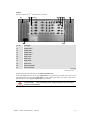


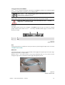
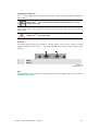
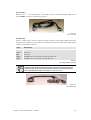
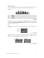
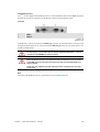


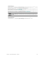

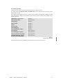
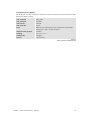


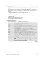

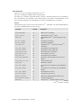


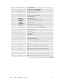


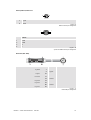
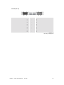


![OverView Control Manager user`s manual - operator [v04]](http://vs1.manualzilla.com/store/data/005659468_1-4c522981c7089838b286d7fbb1120c24-150x150.png)