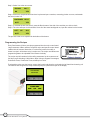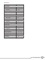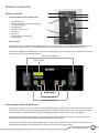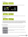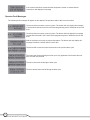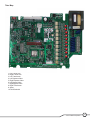
1
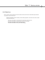
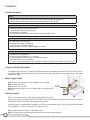
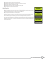
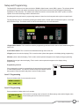
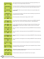
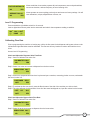
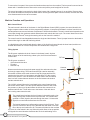
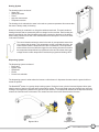
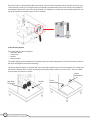
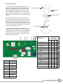
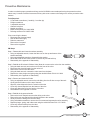
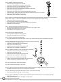
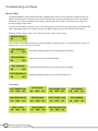
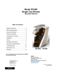
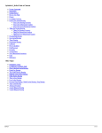
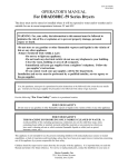
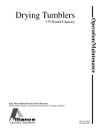
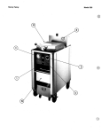
BUNN® TECHNICAL TRAINING
Dual SH BrewWISE ® DBC
Index
Unit 1: Installation
Site Requirements .............................................................................................................. 4
Location of the Serial Number .......................................................................................... 4
Water Supply Install ........................................................................................................... 4
Electrical Install .................................................................................................................. 4
Initial Start-Up ..................................................................................................................... 5
Unit 2: Setup
Setup and Programming .................................................................................................... 7
Programming Lockout ................................................................................................. 7
Level 1 Programming ......................................................................................................... 7
Level 2 Programming ......................................................................................................... 7
Level 3 Programming ......................................................................................................... 9
Calibrating Flow Rate ......................................................................................................... 9
Check and Adjust the Dispense Valve Flow Rate ..................................................... 9
Check and Adjust the Bypass Valve Flow Rate ........................................................ 9
Programming the Recipes ................................................................................................. 10
Default Values ..................................................................................................................... 11
Unit 3: Machine Composition
Exterior Overview ............................................................................................................... 13
Product Outlets and Removable Parts ...................................................................... 13
User Interface ............................................................................................................... 13
Accessing the Inside of the Brewer .................................................................................. 13
Machine Function and Operations.................................................................................... 14
Main Control Board ...................................................................................................... 14
Filling System ............................................................................................................... 14
Heating System ............................................................................................................ 15
Dispensing System ...................................................................................................... 15
Coffee Holding System ................................................................................................ 16
The Soft Heat® Server ........................................................................................... 17
Unit 4: Preventive Maintenance
Preventive Maintenance..................................................................................................... 19
PM Steps ............................................................................................................................. 19
Unit 5: Troubleshooting
Service Tools ...................................................................................................................... 22
Test Outputs ................................................................................................................. 22
Test Switches ...............................................................................................................23
Test Servers .................................................................................................................. 23
Test Frequency ............................................................................................................. 23
Service Fault Messages ..................................................................................................... 23
Operator Fault Messages................................................................................................... 24
Triac Map ............................................................................................................................. 25
© 2009 Bunn-O-Matic Corporation. All Rights Reserved
Rev. A
UNIT 1 INSTALLATION
Unit Objectives
Given a realistic scenario depicting a new site install, the learner will be able to install and setup the brewer
for customer turnover without error.
Given a new machine, all the necessary tools and safety equipment, the learner will be able to install
the brewer without error.
The learner will be able to verify that the site requirements have been met.
The learner will be able to locate and document the serial number.
The learner will be able to hook up the water supply.
The learner will be able to hook up the electrical supply.
Installation
Site Requirements
Space
• Counter able to support the weight of the machine, approximately 185 pounds wet
• Counter area able to support machine placement 35.8”H x 18”W x 21.2”D
Water Treatment
•
•
•
•
Sediment filtration to reduce large particles
Taste and odor filter to remove chlorine
Scale filtration as needed
For best results a Bunn Easy Clear® filtration system should be used
Plumbing
•
•
•
•
¼” flare fitting on the machine
Dedicate water supply with shut-off
Connected to the cold water supply
Water pressure 20-100psi, 50psi if regulator is needed
Electrical
•
•
•
•
•
120/208VAC or 120/240VAC
3 wire plus ground (Neutral, L1, L2, ground)
30 amp dedicated circuit (breaker, plug, and receptacle)
Receptacle within 5 feet of machine
If a power cord is not attached to the machine the technician will have to supply and install the cord
Location of the Serial Number
The machine’s serial number is located on the data plate which is attached to the bottom of the front panel. The serial number begins with the word DUAL. The complete serial number will need to be documented on all work orders
and warranty tags.
Water Supply Install
Step 1: Check water pressure, install a regulator if above 90psi.
Step 2: Flush water lines.
Step 3: Install shut-off valve.
Step 4: Attach the water line to the ¼” flare fitting on the bottom of the
machine.
Water Supply
20-90 psi
1/4” flare fitting
Electrical Install
Refer to the electrical section of the machine’s data plate to select the
proper power cord, plug and receptacle for the brewer. An electrician must provide electrical service as specified in
conformance with all local, state, and federal electrical codes.
Since the brewer is thermostatically controlled, 100% of the circuit breaker can be used. This will allow the machine
to be installed on a 30 amp circuit instead of a 50 amp circuit.
Step 1: Remove the front panel (11 flat head screws).
Step 2: Feed the power cord through the strain relief in the bottom of the machine.
4
Dual SH BrewWISE® Training Manual
Step 3: Attach the wire ends to the terminal block.
Step 4: Attach the ground wire to connector on the frame cross bar.
Step 5: Check that all connections are tight.
Step 6: Tighten the strain relief and replace the front panel.
Step 7: Plug the unit into the power source.
PLEASE WAIT
TANK FILLING
Initial Start-Up
Note: If the brewer has a serial number prior to DUAL0680000 the machine does not have
an On/Off switch and will turn on when the unit is plugged in.
Step 1: Flip the On/Off switch to the On position.
HEATING
WATER TEMP ###°
When the machine is turned on, it will begin to fill the tank. After the tank fills the machine
will automatically begin the heating cycle. This will take approximately 20 minutes.
Once the water temperature has reached the programmed Brew Lockout temperature it will
display the ready screen. The machine will continue to heat until it reaches its programmed
shut-off temperature.
READY TO BREW
WATER TEMP 200°
5
Bunn-O-Matic Corporation
UNIT 2 SETUP
Unit Objectives
Given a realistic scenario depicting a new site install, the learner will be able to install and setup the brewer
for customer turnover without error.
Given an installed machine, all the necessary tools and safety equipment, the learner will be able to
set the machine up for initial operation.
The learner will be able to power on the machine.
The learner will be able to perform the calibrations.
Setup and Programming
The BrewWISE® software is the latest evolution of BUNN’s digital brewer control (DBC®) system. The software allows
precise brewing control and multiple extractions recipes to be stored on the brewer and onboard troubleshooting
capabilities for the technician. The software also allows the brewer to communicate with a DBC® grinder, to reduce
operator errors when selecting products and batch sizes.
Accessing and using the brewer’s programming features is done from the front panel and requires no special tools.
The programming menu is accessed by pressing the hidden switch, located under the trademark symbol, on the right
side of the Bunn logo. The hidden switch on the left side will allow you to scroll backwards.
2
3
4
1
5
1 Right Hidden Switch: This is used to access the programming mode and is also used to scroll forward through the
function list.
2 Left Hidden Switch: This is used to scroll backwards through the function list.
3 Digital (lower left under the display): This is used to select options that appear on the display during programming.
4 Brewer (center under the display): This is used to select options that appear on the display during programming.
5 Control (lower right under the display): This is used to select options that appear on the display during
programming.
Programming Lockout
If the programming cannot be accessed then the programming lockout switch
is in the Disable position. The switch is located on the control board. Remove
the top panel, locate the switch and place it into the Enable position.
DISABLE
ENABLE
PROGRAM
Level 1 Programming
Press the hidden switch for one second to access.
BREW LOCKOUT ?
ON
DONE OFF
Level 2 Programming
Press and hold the hidden switch for 5 seconds.
SET NEW RECIPE ?
NO
YES
This screen is for setting water volumes for the Brew (dump) valve and the Bypass valve.
Pulse Brewing will also be found in this screen.
7
Bunn-O-Matic Corporation
REVIEW RECIPES ?
NO
YES
ASSIGN RECIPE ?
NO
YES
COPY SETTINGS ?
NO
YES
ENABLE ADS ?
NO
DONE
YES
SET TEMP 200O
(-)
DONE
DONE
(+)
XXX REFILL 155
(-)
DONE
(+)
L SPRAY Oz/M: 39.2
(-)
DONE
(+)
R SPRAY Oz/M: 39.2
(-)
DONE
(+)
L BYPASS Oz/M: 24.1
(-)
DONE
(+)
R BYPASS Oz/M: 24.1
(-)
DONE
(+)
CALIBRATE FLOW ?
NO
NO
YES
FUNNEL DETECT ?
DONE
YES
SERVER DETECT ?
NO
If one NO NAME coffee is set up, this function allows you to copy the settings to the
opposite side.
This screen allows the operator to utilize the screen for advertising; a tag card can be
programmed with your message.
Sets the temperature of the brew tank.. Range of 185°F to 205°F
This function sets the minimum temperature to start a brew cycle (BREW LOCKOUT).
Range of 179°F min. to 203°F max. (or within minimum 2° of tank target temp).
Set the sensitivity of the refill circuit. Range of 20 (Open circuit) to 230 (Short circuit).
Can be adjusted for different water conditions. Increase number for very soft water.
Default is 155
Enter new number for each spray head, after doing CALIBRATE FLOW and measuring
output.
Enter new number for each spray head, after doing CALIBRATE FLOW and measuring
output.
Enter new number for each bypass valve, after doing CALIBRATE FLOW and measuring
output.
Enter new number for each bypass valve, after doing CALIBRATE FLOW and measuring
output.
Technician can measure actual flow rate through all 4 valves with 60 second flow test.
YES
BREW COUNTERS ?
NO
This function allows for assigning a coffee name other than No-Name to the brew switch.
Note: This function is only on machines with serial number DUAL0680000 and later.
(+)
SET READY 195O
(-)
This screen allows the user to preview recipes that are already programmed you can
also modify or set the recipes manually in this screen.
DONE
Allows the operator to track the number of brew cycles completed left, right, Combined
(resettable) & Combined (no reset).
YES allows the operator to prevent the start of a brew cycle, must have a Smart funnel.
NO does not need Smart funnel to brew.
Prevents the start of a brew cycle if a Soft Heat® server is not in place.
YES
8
Dual SH BrewWISE® Training Manual
FACTORY DEFAULTS
NO
YES
SERVICE TOOLS ?
NO
YES
Allows technician 4 test modes, operate all load components, test touch pad switches,
test server detection, and test frequency of funnel sensing coils.
Allows operator to erase anything previously set and returns to factory settings. You will
lose calibrations, recipes, adjusted brew volumes, etc.
Level 3 Programming
Press and hold the right hidden switch for 10 seconds.
Insert a digital thermometer probe into the water tank and wait for the temperature reading to stabilize.
200o
CAL
200o
(-)
DONE
(+)
Calibrating Flow Rate
Prior to programming the machine or brewing any coffee, the flow rates for the dispense and by-pass valves on the
left-hand and right-hand sides must be calibrated. The flow rate will vary location to location and machine to machine.
Access Level 2 Programming.
Check and Adjust the Dispense Valve Flow Rate
Step 1: Scroll to Calibrate Flow select Yes.
CALIBRATE FLOW ?
NO
YES
Step 2: Select Yes at the next screen to dispense from the brew valves.
SPRAY HEAD CAL ?
NO
YES
Step 3: Ensure the sprayhead and funnel are in place and put a container, measuring pitcher or server, underneath
the funnel, select Yes.
CONTAINER
QUIT
RDY ?
YES
Step 4: To activate the flow rate check, press the Brew button of the side of the machine you wish to check.
Step 5: The valve will open for 60 seconds. Once all of the water has dripped out, input the volume into the brewer.
LEFT
QUIT
OZ
36.0
YES
Check and Adjust the Bypass Valve Flow Rate
Step 1: Scroll to Calibrate Flow select Yes.
CALIBRATE FLOW ?
NO
YES
Step 2: Select No at the next screen to dispense from the brew valves.
SPRAY HEAD CAL ?
NO
YES
9
Bunn-O-Matic Corporation
Step 3: Select Yes at the next screen.
BYPASS
NO
CAL ?
YES
Step 4: Ensure the sprayhead and funnel are in place and put a container, measuring pitcher or server, underneath
the funnel, select Yes.
CONTAINER
QUIT
RDY ?
YES
Step 5: To activate the flow rate check, press the Brew button of the side of the machine you wish to check.
Step 6: The valve will open for 60 seconds. Once all of the water has dripped out, input the volume into the brewer.
LEFT
QUIT
OZ
24.2
YES
The process needs to be repeated for both sides of the brewer.
Programming the Recipes
Every Dual brewer will have a recipe programmed into the main control board.
Large customers of Bunn will have a specific recipe and specific control board
installed in their brewers. Most often, if a technician is asked to modify a
brewer’s recipe it will be done using a recipe card. The recipe card allows new
programming data to be uploaded to the brewer wirelessly.
The recipe card will contain all of the coffee parameters for the customers coffee flavor profile including: Coffee Name, Brew Volumes, Bypass Percentages,
Pulse Brew Times, PreInfusion Times, and Drip-Out Times.
TAG CONTAINS RECIPE
Instructions for transfer to brewer.
) emove both funnels.
) old tag under left sense coil.
) isplay will show “TAG CONTAINS
”
) ollow instructions on screens.
NAME:_________________
T oday’s S pec ial
To upload the recipe onto the brewer, remove the funnels and place the card under the left hand funnel sensing coil.
The machine will recognize the recipe card and prompt to upload the recipe on the display.
TAG CONTAINS
RECIPE FOR
“COFFEE NAME”
SHOW
10
Dual SH BrewWISE® Training Manual
QUIT
SAVE
Default Values
Brew Lockout
YES
Brew Volumes
Small batch
64 OZ.
Medium batch
128 OZ.
Large batch
192 OZ.
Bypass Percentage
Small batch
0%
Medium batch
20%
Large batch
20%
Pulse Brew Times
Small batch
:40/:10/:5
Medium batch
Off
Large batch
Off
Pre-Infusion Times
Small batch
Off
Medium batch
Off
Large batch
Off
Drip Out Times
Small batch
1:00
Medium batch
1:30
Large batch
2:00
Enable Ads
Yes
Brew Temperature
200º F (93º C)
Ready Temperature
195º F (91º C)
Refill
155
Spray (Oz/Minute)
39.2
Bypass (Oz/Minute)
24.1
Funnel Detect
Yes
Server Detect
Yes
11
Bunn-O-Matic Corporation
UNIT 3 MACHINE COMPOSITION
Unit Objectives
Given a realistic scenario in which the learner has access to the machine’s internal components the learner
will understand the composition and functions of the brewer.
Given a realistic scenario requiring the learner to access the internal components of the machine the
learner will be able to remove the front panel and top cover.
The learner will disconnect the electrical and water supply.
The learner will remove the front panel and top cover.
Given an operating machine the learner will be able to give a general explanation of how the unit
operates.
The learner will be able to identify the functions of the main control board and identify the
components that correspond to each triac.
The learner will be able to identify the components and functions of the filling system.
The learner will be able to identify the components and functions of the heating system.
The learner will be able to identify the components and functions of the dispensing system.
The learner will be able to identify the components and functions of the coffee holding system.
Machine Composition
Exterior Overview
Product Outlets and Removable Parts
•
•
•
•
•
•
•
•
•
2
1
3
5
6
User interface (1)
Display (mounted to the control board) (2)
Hot water outlet (3)
Sprayhead (4)
Funnel sensing coil (5)
Funnel (6)
Server (7)
Server electrical contacts (8)
Data plate (9)
4
7
9
8
User Interface
The user interface is a membrane switch adhered to the front of the brewer. The membrane is connected to the control board by a ribbon cable. The user interface allows the user to select product size and begin a brew cycle.
The machine’s display is mounted to the control board. The display is visible on the front of the machine and provides
information to the user and to the technician.
Batch Selector Switches
Display Screen
On/Off Switch
Brew Start Switch
Funnel Sensing Coils
Accessing the Inside of the Brewer
The majority of service work done to the Dual SH BrewWISE® brewer will require the service technician to access the
inside of the unit. The brewer has three removable panels to facilitate access- the front panel, the top panel, and the
server base panel. Depending on the repair the technician may have to remove one or all of these panels.
In order to work safely the power should be disconnected prior to removal of any body panel. Once the panels are
removed the power can be reconnected in order to troubleshoot the machine.
The top panel is secured with 4 small flat head screws. To the remove the panel, remove the four screws, lift the front
of the panel up and slide the rear backwards to unhook the panel from the brewer’s body.
13
Bunn-O-Matic Corporation
To remove the front panel, first remove the funnels and servers from the machine. The front panel is secured to the
brewer with 11 standard screws. Remove the screws and pull the panel straight off of the unit.
The server base plate is secured to the body of the brewer with 4 standard screws, 2 on each side. Remove these
four screws and slide the base plate forward. Before removing the base plate from the machine, the wires will need
to be disconnected from the server contacts.
Machine Function and Operations
Main Control Board
The main control is the brain of the brewer. In the Digital Brewer Control (DBC®) system, the control board is the
single component that contains all of the programming software, it interprets all the data it receives from the level
and temperature sensors and activates components to fulfill those demands. The main control board responds to the
users input through the membrane switch and activates and controls the brew cycle. The control board can receive
data from Smart Funnels® through the sensing coils on the front of the machine.
The control board is interchangeable between the single and dual brewers. There is jumper located on the board to
select either single or dual with dual being default.
In a digital brewer the control board takes the place of the liquid level control board, the timer board, and the mechanical thermostat. All of these components are combined into a single unit.
Filling System
The fill system maintains the level of water in the brewer’s tank. Anytime
water is drawn off of the tank during a brew cycle, the fill circuit activates to
refill the tank.
Fill Tube
The fill system consists of:
• 120V solenoid inlet valve
• Fill probe
• Overflow cup
Water enters the brewer through the water supply line and enters the chassis through copper tubing. The water flows through a strainer assembly;
this strainer contains a fine mesh screen to keep any large particles from
entering the inlet valve. It is important to note that there is no flow control
device in this strainer. From the strainer the water flows to the fill solenoid;
there is a built in water hammer arrestor on the line between the strainer
and the solenoid valve.
Hammer
Arrestor
Solenoid
Strainer
The 120VAC solenoid inlet valve is activated by the control board anytime
the brewer calls for water. The valve opens and allows water to flow, under
line pressure, to the top of the tank where the silicon tube connects to an
stainless steel fill tube. The fill tube runs to the bottom of the tank where
the incoming water enters the tank.
Float Switch
The control board monitors the level of water in the tank through a low
voltage level probe mounted to the top of the tank. The control board
grounds a 2.5VAC signal to the tank through the water. If it looses this
signal, the control board will activate the inlet valve.
The brewer features an overflow safety system for the fill circuit. There
is a tube mounted on the top of the tank that will drain water if the tank
fills to the top and continues to fill. The water will drain into the overflow
cup; there is a float switch in the cup. When this switch floats to its top position
this signals the control board to deactivate the fill circuit and heating circuit.
14
Dual SH BrewWISE® Training Manual
Heating System
The heating system consists of:
• Water tank
• Heating elements
• Triacs
• High-limit thermostats
• Temperature sensor
The heating circuit maintains the water in the tank at a preset temperature this ensures that
the water is always ready for brewing.
Water for brewing is contained in an 8.4 gallon stainless steel tank. This tank contains 2
heating elements that are powered by the line voltage into the machine. Each heating element is controlled by the control board through triacs mounted on the back of the brewer.
Each heating element circuit has a limit thermostat that will interrupt the circuit if the water
in the tank overheats.
The control board monitors the water in the tank by a temperature sensor that
is in contact with the water. This temperature sensor is a digital thermistor; the
control board reads the temperature as value of resistance. The temperature
sensor allows the control board to trigger the two heating element triacs when
the temperature drops below its programmed value and shut down the trigger
voltage when the water temperature reaches the programmed holding value.
Dispensing System
The dispensing system consists of:
• Brew valve
• Bypass valve
• Sprayhead
• Funnel
• Funnel lock solenoids
The dispensing system is what makes the brewer a coffee brewer. It dispenses the water onto the ground coffee to
create the product.
The BrewWISE® brewer is a gravity dump brewing system. During the brew cycle the brew and bypass valves open
allowing water to flow from the tank and out the product outlets. The control board opens and closes these valves according to its programming based on the specific recipe called for. The sprayhead, attached to the dispense solenoid,
controls the outlet flow rate of the water. The number and size of the holes determines the flow rate.
Bypass Valve
Dispense Valve
15
Bunn-O-Matic Corporation
Since the brewer incorporates Pulse Brew technology, the brew valves and bypass valves will open and close up to
12 times during a brew cycle. During the brew cycle and the programmed drip out time the funnel lock solenoid will
be engaged to prevent the funnel from being removed. It is important to note that the control board supplies DC voltage to the funnel lock solenoid to prevent it from vibrating.
Coffee Holding System
The coffee holding system consists of:
• Soft Heat® server
• Transformer
• Rectifier
• Spring contacts
The coffee holding system maintains the finished product at the desired temperature. The brewed coffee is stored in
the server utilizing Bunn Soft Heat® technology.
The brewer provides 24VDC to the Soft Heat® servers through contacts in the front of the machine. Line voltage from
the brewer is stepped down to 24VAC and then goes through a bridge rectifier to convert it to DC. There is a 4amp
circuit breaker to protect the contacts.
Output
Receptacles
Step-Down
Transformer
16
Dual SH BrewWISE® Training Manual
Rectifier
Circuit
Breaker
The Soft Heat® Server
The server stores and dispenses the brewed coffee.
Soft Heat® technology allows the coffee to be mainElectrical contacts
tained at a set temperature for a set period of time.
These settings are programmed from the factory but
can be adjusted by customer request. The server
features a safety fresh brew thru-lid, regular and decaf
indicator, a faucet guard, and two carrying handles on
the top.
The server contains the holding vessel for the coffee wrapped in dense insulation. In the bottom of the
server is a 72W 24VDC heating element, along with
a control board, thermistor, and electrical contacts so
the server can receive power from the brewer. On the
front of the server there is a red LED that indicates the
server is in contact with the brewer.
Red LED
Heating element
Control board
The Soft Heat control board contains controls for
temperature and holding time. The holding time is adjusted by turning the small white dial. The temperature
can be adjusted by cutting or reconnecting leads to
resistors. Note- the resistor can only be reconnected
by soldering the connections.
®
Control Temperature
Shown in ºF
Number
Minutes
Jumper Program
Position
I = In O = Cut
1
2
3
4
176.0
I
I
I
O
176.9
I
I
O
I
177.8
I
I
O
O
178.7
I
O
I
I
179.6
I
O
I
O
180.5
I
O
O
I
181.4 (Default)
I
I
I
I
182.3
I
O
O
O
183.2
O
I
I
I
184.1
O
I
I
O
185.0
O
I
O
I
185.9
O
I
O
O
0
Off
186.8
O
O
I
I
1
30
187.7
O
O
I
O
2
45
188.6
O
O
O
I
3
60
189.5
O
O
O
O
4
90
5
120
6
150
7
180
8
210
9
240
17
Bunn-O-Matic Corporation
UNIT 4 PREVENTIVE MAINTENANCE
Unit Objectives
Given a realistic scenario depicting a machine requiring a preventive maintenance, the learner will be able to
identify which elements of a component need to be serviced without error.
Given a machine, all the necessary tools and safety equipment, the learner will be able to identify the
components that need to be serviced for the PM.
Preventive Maintenance
In order to maintain proper operation and long service life BUNN recommends performing the preventive maintenance every 6 months. Individual customers will vary with some customers choosing not to receive preventive maintenance.
Tools Required:
• 2 Flat blade screwdrivers (1 small tip, 1 medium tip)
• Phillips screwdriver
• 2 adjustable wrenches
• Channel lock pliers
• Needle nose pliers
• Basin wrench Bunn PN: 01060.0000
• Deliming tool Bunn PN: 38227.0000
Prior to servicing the brewer:
• Disconnect the electrical supply
• Shut off the water supply
• Drain the water tank
• Remove the front panel
• Remove the top panel
PM Steps
Step 1: Disassemble and clean the strainer assembly
□ Using an adjustable wrench, loosen the flare nuts on the top and bottom of the
strainer assembly
□ Using two adjustable wrenches, disassemble the strainer
□ Rinse and scrub the fine mesh screen to remove any mineral build-up
□ Reassembly is the opposite of disassembly
Step 2: Rebuild the fill solenoid- Skinner Valve (Note do not remove the valve from the machine)
□ Using the basin wrench, remove the nut from the front of the valve
□ Disconnect the electrical leads from the valve coil
□ Remove the coil from the valve stem
□ Using the basin wrench, unscrew the valve stem from the base
□ Replace the valve plunger and spring using the rebuild kit Bunn P/N: 01111.0000
□ Reassembly is the opposite of disassembly
Step 3: Remove and clean the fill tube
□ Using an adjustable wrench remove the tube fitting from the fill tube on top of the tank
□ Gently pull the fill tube out of the top of the tank
□ Wipe any mineral deposits from the exterior of the tube
□ Clean any mineral deposits from the bottom of the tube
□ Clean any obstructions from the interior of the tube
□ Reinstallation is the opposite of removal
Step 4: Rebuild the by-pass solenoids
□ Remove the hose clamps that secure the tubing to the valve
□ Remove the two nuts that hold the solenoid bracket to the machine
□ Gently remove the tubing from the valve body
□ Using a flat blade screwdriver, remove the four screws and separate the valve assembly
□ Replace plunger, spring, and rubber seat using the rebuild kit Bunn P/N: 11517.0008
□ Clean any mineral build-up from the valve
□ Reassembly is the opposite of disassembly
19
Bunn-O-Matic Corporation
Step 5: Rebuild the dispense solenoids
□ Disconnect the wire leads to the solenoid
□ Unscrew the sprayhead from the bottom of the valve
□ Remove the securing nut from the bottom of the valve
□ Remove the clip from the tube on the valve fitting
□ Remove the tube from the barbed fitting on the rear of the valve
□ Remove the valve from the brewer
□ Remove the four Phillips head screws and disassemble the valve
□ Replace plunger, spring, and rubber seat using the rebuild kit Bunn P/N: 11517.0008
□ Clean any mineral build-up from the valve
□ Reassembly is the opposite of disassembly
Step 6: Clean the tank fittings that supply water to the solenoid valves (Note depending on the age of the brewer this
will be either a single “T” connector or individual connectors for the dispense and bypass tubes.)
□ Remove the clip from the end of tubes
□ Gently remove the tubing from the tank fittings
□ Use a screwdriver to remove and mineral build-up from the fittings
□ Reattach the tubing and clips
Step 7: Remove and clean the temperature sensor
□ Gently pull the temperature sensor from the grommet in the top of the tank
□ Wipe any mineral build-up from the sensor
□ Reinstallation is the opposite of removal
Step 8: Remove and clean the fill probe
□ Gently pull the fill probe out of the grommet
□ Wipe any mineral deposits off of the probe
Step 9: Remove and clean the sprayheads
□ Using the pointed end of the deliming tool, remove any mineral build-up from the sprayhead outlet holes
Step 10: Replace the seat cups in all the Soft Heat server faucets (annually)
□ Ensure the server is completely empty
□ Unscrew the faucet bonnet from the assembly
□ Remove the old faucet seat cup
□ Install the new seat cup Bunn P/N: 00600.0000
□ Reassembly is the opposite of disassembly
Step 11: Replace the seat cup in the hot water faucet (annually)
□ Unscrew the faucet bonnet from the assembly
□ Remove the old faucet seat cup
□ Install the new seat cup Bunn P/N: 02766.0000
□ Reassembly is the opposite of disassembly
Step 12: Check funnels, handle and tip are tight
□ Ensure the screw securing the handle to the funnel is tight
□ Ensure the funnel tip, the bottom outlet, is tight
Step 13: Examine power cord for any damage
S MA R T
F U N NE L
Step 14: Examine water supply for any leaks
Step 15: Check the funnel lock solenoids for proper operation (Note the brewer must be on to perform this step)
□ Manually activate each funnel lock in the Systems Tools menu
Step 16: Calibrate flow rates (Note the brewer must be on to perform this step)
□ Follow the procedures in section 2 of this manual
Step 17: Check the Soft Heat® servers for proper operation (Note the brewer must be on to perform this step)
□ Red LED should be on
□ Bottom panel inside the server should be hot to the touch
20
Dual SH BrewWISE® Training Manual
UNIT 5 TROUBLESHOOTING
Unit Objectives
Given a realistic scenario depicting a broken machine, the learner will be able to effectively troubleshoot,
diagnosis, and repair the problem returning the machine to normal operation.
Given a machine displaying an error message, all the necessary tools and safety equipment, the
learner will be able to access the software and diagnosis the problem.
The leaner will be able to access the programming menu.
The learner will be able to navigate to the Service Tools menu.
The learner will be able use the Service Tools menu to test inputs or outputs.
Given a list of error messages and issues, the learner will be to identify the probable cause of the
message or issue.
Given a brewer with a defective component, the learner will be able to test the component to
determine the cause of the defect.
Troubleshooting and Repair
Service Tools
The Dual BrewWISE® brewer features on-board troubleshooting. Since all of the machine’s components are controlled or activated by the control board you can activate and test components individually from the user interface.
This allows you to listen to solenoid valves opening, observing the flow of water or test to see if a component is
receiving voltage using a meter.
The Service Tools option is located in Level 2 of the programming. Enter Level 2 programming by pressing and holding the right hidden switch for 5 seconds. Use the right hidden switch to scroll to the “Service Tools” screen.
Press the Control button to select “Yes”. This will enter the “Service Tools” feature.
SERVICE TOOLS ?
NO
YES
In the “Service Tools” selection their are 4 screens available, by selecting “Yes”, you will enter that test function, by
selecting “No” you will move to the next test.
TEST OUTPUTS?
NO
YES
TEST SWITCHES?
NO
YES
TEST SERVERS?
NO
Test Outputs supplies voltage to load components in the brewer.
Tests the inputs from the membrane switch.
The machine will indicate if it sees a server in place or missing.
YES
TEST FREQUENCY?
NO
Indicates the transmit frequency of the funnel sensing coils.
YES
Test Outputs
LEFT BREW VALVE
ON
NEXT
OFF
RIGHT BREW VALVE
ON
NEXT
OFF
REFILL VALVE
ON
NEXT
OFF
22
Dual SH BrewWISE® Training Manual
LEFT BYPASS
ON
NEXT
OFF
RIGHT BYPASS
ON
NEXT
OFF
TANK HEATERS
ON
NEXT
OFF
LEFT FUNNEL LOCK
ON
NEXT
OFF
RIGHT FUNNEL LOCK
ON
NEXT
OFF
HEATER CONTACTOR
ON
NEXT
OFF
LEFT SERVER
ON
NEXT
OFF
RIGHT SERVER
ON
NEXT
OFF
Test Switches
TEST SWITCHES?
NO
NOTHING PRESSED
YES
Press any of the input buttons on the membrane switch, the display will show which button is being pressed.
Test Servers
TEST SERVERS?
NO
YES
SERVER REMOVED
IN PLACE
Insert or remove a server from each side of the brewer. The brewer indicates if the server is removed or in place
based on the transformer load.
Test Frequency
TEST FREQUENCY?
NO
YES
SERVER124.7
REMOVED
Khz .5
5. 124.7 Khz
IN PLACE
The funnel sensing circuit is tuned to 125 kHz. If the circuit is not tuned correctly, then the funnel information will not
be transferred to the brewer. Therefore, the microprocessor is constantly fine tuning to get as close as possible to
125 kHz. It has eight possible tuning steps numbered 0 - 7. When you look at the “TEST FREQUENCY” screen you
see something like (124.7 KHZ .5) The 124.7 is the frequency, and the 5 is the tuning step. The decimal point next to
the 5 indicates the funnel is being detected; if the funnel is removed the decimal point should turn off.
Service Fault Messages
The brewer features several error messages for problems occurring within the machine. These error messages be
show up on the display.
This indicates that the tank overflow is full. The unit may be overfilling or boiling.
This message will appear if the control board does not see the programmed water
temperature within 60 minutes.
This message will appear if the control board does not see the tank fill within 30 minutes.
23
Bunn-O-Matic Corporation
If the control board loose contact with the temperature sensor or senses shorted
connection it will display this message.
Operator Fault Messages
The following fault messages will appear on the display if the operator needs to take corrective action.
The brewer does not sense a server in place. The brewer will only display this message
if Yes has been selected in the Server Detect programming menu. Otherwise the unit will
brew.
if
The brewer does not sense a funnel in place. The brewer will only display this message
Yes has been selected in the Funnel Detect programming menu. Otherwise the unit will
brew.
Wait for the brewer to heat up to proper temperature. The brewer will only display this
message if the Brew Lockout feature is set to NO.
The brewer did not see the funnel removed since the previous brew cycle.
The funnel was removed during the brew cycle. Only applicable if the brewer does not
have a funnel lock solenoid.
The server was removed during the brew cycle.
The brew switch was turned off during the brew cycle.
24
Dual SH BrewWISE® Training Manual
Triac Map
1
2
3
4
5
6
7
8
9
10
1. Left Funnel Lock
2. Right Funnel Lock
3. Left Transformer
4. Left Dispense Valve
5. Right Dispense Valve
6. Left Bypass Valve
7. Right Bypass Valve
8. Right Transformer
9. Spare
10. Refill Solenoid
25
Bunn-O-Matic Corporation