1
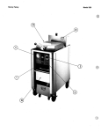
odel
301/302/303
This section provides operating procedures for the Henny Penny OG/OE-301/302/303. Sections 1, 2, and 3 should be read
and all instructions should be followed before operating the
fryer.
3-2.
Figures 3-1 through 3-8 identify and describe the function of
all operating controls and components.
Page 3-10 describes the function of electromechanical controls,
or units without computer controls.
Fig.
No.
Item
No.
3-l
1
Power Switch
This two position rocker type switch controls the power to the
fryer when in the on position.
3-1
2
Digital Display
The digital display is to show the shortening temperature, as
well as the timer countdown in the frying cycle. The temperature
of the shortening can be determined by depressing the
temperature switch. If the temperature is below 250°F (121°C),
the digital display will read “LO”. If the temperature exceeds
390°F (199”C), the display will read “HI”. Any temperature
between these two settings will be displayed.
3-l
3
Timer Switch
The right timer can be activated or reset by gently depressing
the timer switch. The same holds true for the left timer switch.
The left display shows the left timer information and the right
display shows the information for the right timer.
3-l
Set Switch
The set switch is used to set the cooking cycles and to enter
the special program modes.
3-l
Exit Melt Switch
The exit melt swtich is used to bypass the melt cycle. By pressing and holding the exit melt switch for five seconds, the heat
will come on continuously.
Temperature Switch
By pressing the temperature switch (indicated by thermometer),
the actual shortening temperature will show on the left display
and the setpoint temperature on the right display.
6
escription
Function
Melt LED
When the melt LED is flashing, the fryer is in the melt cycle.
When the temperature of the shortening reaches approximately
250°F (121”C), the melt LED will go off and automatically
switch to the heat cycle.
When using solid shortening, it is recommended to melt the
shortening on an outside heating source before placing shortening in the cookpots. Heating elements, and the slope of the gas
cookpot must be completely submerged in shorting. Fire could
result, or damage to the cookpot could result.
Ready LED
The ready LED illuminates when the temperature of the
shortening is near the setpoint temperature. (It will illuminate
if the temperature is 5°F (or “C) more than the setpoint
temperature.)
Head LED
The heat LED illuminates when the heat comes on.
Product LED
The product LED flashes while in the program modes, and a
new product can be selected at this time.
Time LED
The time LED flashes while in the program mode and a new
fry time can be programmed.
Temperature LED
The temperature LED flashes while in the program mode and
the setpoint temperature can be programmed.
Alarm LED
The alarm LED flashes while,the program mode. Up to four
alarms can be programmed in a cook cycle.
ternI
No.
14
Other LED
The other LED flashes while in the high level program mode
and special program modes only. Several parameters can be programmed at this time.
15
Idle LED
The idle LED illuminates
switch is pressed for two
the other product LEDs
regulate the shortening
temperature.
16
Up and Down
Switches
Two sets of up and down switches (denoted as triangles) are
on the control. These switches are used in programming and
product selection. A product is selected by pressing and holding
either the up or down switch for two seconds. To select both
the right and left products at the same time the programmed
set point temperature must be the same.
3-2
17
Fuses (electric only)
The fuses, located on the panel behind door, are protective
devices that break the circuit when the current exceeds the rated
value. The 5 amp fuses provide an overload protection for the
control panel.
3-2
18
High Limit Reset
This manual reset, located on panel behind door, must be pushed
up in the event the high limit trips. This red button will manually
reset the high limit. A high limit protects each cookpot.
3-3
19
Contactors
(electric only)
The contactors are the relays that route power to the heating
elements. One relay coil is in series with the high limit
temperature control, and the other relay coil is in series with
the heat control circuit, which is the mercury contactor.
3-3
20
Thermal Sensor
The thermal sensor, located behind the control panel, determines
the shortening temperature.
3-l
&I-;j
escriptiori
when the right timer up and and down
seconds. The indicator passes through
to the idle LED. The control will then
temperature at a lower programmed
odel
Drain Interlock
(Hidden behind
bracket)
The drain interlock switch is a microswitch that provides protection for the heating elements in the event an operator drains
shortening from the frypot while the power switch is on. The
drain switch is designed to automatically shut off the control
system when the drain valve is opened. A drain interlock switch
protects each cookpot.
It is recommended to turn all power off before opening
drain valve.
Drain Valve
The drain valve is a two-way ball valve and is normally in the
closed position. Turn the handle to the open position to drain
the shortening from the frypot.
Open the drain valve slowly to eliminate splashing of hot
shortening. Severe burns could result.
3-6
24
Filter Union
The filter union connects the filter assembly to the filter pump.
It is easily disconnected to allow removal of the filter and filter
drain pan.
odd 0
Fig.
NO.
Rte
No.
3-6
25
301/302/303
Function
Filter Drain Pan
The .removable filter drain pan houses the filter and catches the
shortening when it is drained from the frypot. It is not to be
used to remove and discard the shortening when the shortening needs replaced.
Use extreme care when handling the drain pan or any metal
which comes in contact with hot shortening. Do not move
drain pan with hot shortening in pan. Severe burns could
result. It is recommended to use gloves.
26
Filter Pump Switch
This two position rocker switch controls the power to the
filter pump motor.
3-6
27
Oil Return Line
The detachable oil return line pivots to reach all three
cookpots when pumping shortening back into the cookpots.
The return line can be removed and a rinse hose connected
to unit to discard shortening from unit.
3-8
28
Gas Shut-Off Valve
(gas only)
Each cookpot has its own gas shut-off valve on thegas line
going to the gas valve.
3-8
29
Gas Control Valve
(gas only)
Each cookpot has its own gas control valve which controls
the flow of gas to burner assembly. It requires manual pilot
lighting.
30
Gas Solenoid
(gas only)
The gas solenoid shuts the flow of gas off to the burner
in this unit that the high limit kicks out, and is present for
each cookpot.
Y
el 0
.
%
0
3
Y
re 3-
re
ode!
0
Main Power Switch
The main power switch is a two,way switch. Move the
switch to the position marked ON to operate the fryer.
Move the switch to the position marked ON to operate the
The thermostat is an electro-mechanical device used to
below the temperature set by the thermostat. It goes off
when the shortening reaches the set temperature.
The timer is an electro-mechanical device that controls the
length of the frying cycle and activates the buzzer when the
frying cycle is complete. Turn the knob to set the black
arrow at the desired frying time. The red arrow will reset
back to the black arrow when the ON/OFF switch is moved
position to start the timer.
Move to the OFF position to stop the buzzer after the frying
cycle. This also will reset the timer to the original setting.
The timer indicating light is a red light which is illuminated
when the timer is on.
It is recommended that a high quality frying shortening be
used in the O&301/302/303 and OG-301/302/303 fry
stations. Some low grade shortenings have a high moisture
content causing foaming and boiling over. The Henny Penny
OE-301/302/303 requires 48 pounds of shortening per
cookpot. The OG-301/302/303 requires 43 pounds per
cookpot. All cookpots have two level indicators
inscribed on the rear of the cookpot wall. The top indicator
shows when the heated shortening is at the proper level.
Cold shortening should be at the bottom indicator, since the
shortening will expand when heated.
Hot shortening must be maintained at the level indicator
on each cookpot, or fire could result. It is also
recommended to use gloves when in contact with hot
shortening. Shortening and all metal parts that are in
contact with the shortening are extremely hot and
severe burns could result.
Moving the fryer with hot shortening in the cookpots or
filter pan is not recommended. Hot shortening can
splash out and severe burns could result.
The Henry Penny Open Fry Station with dual timers contains solid state controls for each cookpot. The following is
brief description of the operating procedures.
1.
Be sure the drain valve is in the closed position.
2.
Place basket support inside of cookpot.
3.
Fill the cookpot with shortening.
When using solid shortening, it is recommended to melt
the shortening on an outside heating source before
placing it in the cookpots. Heating elements and the
slope of the gas cookpot must be completely submerged
in shortening. Fire could result, or damage to the
cookpot could result.
4.
ove power switch to the “ON” position. Unit will
automatically go into the melt cycle. When the
temperature reaches 250°F (121OC) the control will go
into the heat cycle. The shortening will be heated until
the temperature setting is reached.
The melt cycle may be bypassed, if desired, by pressing the
Exit Melt switch and holding it for five seconds.
Do not bypass the melt cycle unless enough shortening has
melted to completely cover all of the heating elements. If
melt cycle is bypassed before all heating elements are
covered, excessive smoking of the shortening or a fire will
result.
5. Press the up or down switch and hold for two seconds
to select a product. The times and temperatures are
preprogrammed.
The operation of the two t,imers is entirely independent.
They may be set, started, or stopped without affecting each
other.
6. Thoroughly stir shortening to stabilize the temperature
throughout the cookpots.
7. When the shortening temperature has reached setpoint,
ready LED will illuminate, indicating to the operator,
they may drop product.
8. Lower basket with product into cookpot and press timer
switch. Countdown will begin.
9. When frying cycle is complete, a pulsating beep will
sound and the display will read “DONE.” Pressing the
timer switch stops the beeping and starts the hold mode.
10. The baskets can be lifted out to drain for the duration
of the hold mode, the display will flash 0O:OOand a
pulsating beep will sound. Pressing the timer switch
resets it back to the cooking time.
ri,~
:%;
:‘>,
:.
,\$‘,,
el 0
Frying breaded food requires frequent filtering. Taste the
cold shortening every day for flavor. Watch the shortening
for foaming during the frying cycle. Discard the shortening as soon as it shows sign of foaming. Clean the cookpot
as follows each time the shortening is changed or filtered.
1. Turn the main switch to the OFF position. Remove and
clean the fry basket in soap and water. Rinse thoroughly.
Best results are obtained when shortening is filtered at the
normal frying temperature.
2. Use a metal spatula to scrape any build up from the sides
of the cookpot. Do not scrape heating elements on electric models, or the slope on the gas models.
The filter pan must be in the proper position beneath the
drain valve. This will prevent the splashing of shortening
on the floor. This splashing could result in severe burns.
3. Open door(s) under unit and open the drain valve very
slowly, half a turn at first and then slowly to the full open
position. This will prevent excessive splashing of the hot
shortening as it drains into the filter drain pan.
4. As the shortening drains from the cookpot, use brushes
to scrape and clean the side of the cookpot and the
heating elements of the electric model. If the drain fills
with breading, use straight white brush to push excess
breading into the drain pan.
5. When all of the shortening has drained, scrape or brush
the sides and the bottom of the cookpot.
6. Rinse the cookpot as follows:
a.
b.
c.
d.
Close the drain valve.
Position return line over empty cookpot.
Move the pump switch to the pump position.
Fill the cookpot l/3 full, then turn off pump.
OEI
enny
301l3~2l303
F
3-5.
(~o~ti~ue~)
If shortening is slow coming from faucet, it is possible that
the filter connecting the union on the filter tube line is not
tightened properly. If so, turn off the pump and use gloves
to tighten the union. This union will be hot. Severe burns
could result.
e. Wash down and scrub the sides of the frypot.
f. After the sides and bottom are cleaned, open the drain
valve.
7. Pump all of the shortening out of the filter pan and back
into the cookpot.
8. When the pump is pumping air only, move the pump
switch from PUMP to OFF.
9. Check the level of the shortening in the cookpot. Add
fresh shortening if necessary, until it reaches the level
indicator line on the rear wall of the cookpot.
Approximately 10 to 12 filterings can be made with one filter
paper envelope, depending on several conditions; the quantity and type of product fried and filtered, the type of
breading used, and the amount of crumb accumulation left
inside the filter drain pan. When the filter screen assembly
and filter paper become clogged and the pumping flow rate
slows down, clean the screen assembly and change the filter
envelope.
10. If frying is to be continued at this time, move the main
power switch back to the “ON” position, and allow time
for reheating of the shortening.
The following steps will help prevent filter pump problems.
1. Make certain the filter paper envelope is properly installed over the filter screens. Make sure the open end
of the envelope is properly folded over and clamped in
place with the retaining clips so that the envelope is
sealed and crumbs cannot enter.
I
2. Make sure all the shortening has been pumped from the
filter lines and the pump by allowing the filter pump
motor to run until no shortening is coming from the
nozzle.
;-,;,?;I
The filter pump motor is equipped with a manual reset button in the event the motor’s thermal protector acuates. This
reset button is located on the rear of the motor. Wait approximately 5 minutes before attempting to reset this protector device.
To prevent burns caused by splashing shortening, the unit’s
filter pump switch must be in the OFF position before resetting the filter pump motor’s manual reset protector device.
The reset button will take some effort to reset. A
screwdriver could be used to press against the reset button
to aid in resetting the protector device.
The filter envelope should be changed after lo-12 filterings
or whenever it becomes clogged with crumbs. Proceed as
follows:
1. Move the main power switch to the OFF position.
2. Disconnect the filter union and-remove the filter drain
pan from beneath the cookpot.
This union may be hot. Use protective gloves or clothes to
prevent burns. Also use care to prevent burns caused by
splashing of hot shortening.
3. Remove drain pan cover from drain pan and lift the
screen assembly from the drain pan.
4. Wipe the shortening and crumbs from the drain pan.
Clean the drain pan with soap and water. Thoroughly
rinse with hot water.
5. Unthread the suction standpipe from
assembly.
the screen
6. Remove the crumb catcher and clean thoroughly with
soap and water. Rinse thoroughly with hot water.
7. Remove the filter clips and discard the filter envelope.
3-8.
8. Clean the top and bottom filter screen with soap and
water. Rinse thoroughly with hot water.
Be sure that the filter screens, crumb catcher, filter clips
and the suction standpipe are thoroughly dry before
assembly of filter envelope or water will dissolve the filter
paper.
9. Assemble the top filter screen to the bottom filter screen.
10. Slide the screen into a clean filter envelope.
11. Fold the corners in and then double fold the open end.
12. Clamp the envelope in place with the two filter retaining clips.
13. Replace the crumb catcher screen on top of the filter
paper. Screw on the suction standpipe assembly.
14. Place complete filter screen assembly back into filter
drain pan, replace cover, and slide pan back into place
beneath the fryer.
15. Connect the filter union by hand. Do not use a wrench
to tighten.
16. The fryer is now ready to operate.
odel
301 l3~2l3Q3
After the initial installation of the fryer, as well as .before
every change of shortening, the cookpot should be
thoroughly cleaned as follows:
I
Melt bypass should be in operation. Refer to section 3-2
“Operating Controls” on Exit Melt Switch.
I
1. Turn the main power switch OFF.
The filter drain pan must be in position under the drain
valves to prevent splashing or spilling of hot liquids which
can cause serious burns.
2. If hot shortening is present in the cookpot, it must be
drained by slowly opening the drain valve handle one half
turn. Leave for a few minutes, then slowly open the valve
to full open position.
3. Close the drain valve. Discard the shortening in the filter
pan using the shortening shuttle. Then install the filter
drain under the fryer, leaving out the filter screen
assembly.
Moving the fry station, or drain pan, with hot shortening
in them is not recommended. Hot shortening can splash out,
and severe burns could result.
4. Fill the cookpot to the level indicator with hot water. Add
4 ounces of fryer cleaner to the water and mix
thoroughly. The fry basket can be placed inside the
cookpot for cleaning.
Always wear chemical splash goggles or face shield and protective rubber gloves when cleaning the cookpot as the cleaning solution is high in alkaline. Avoid splashing or other
contact of the solution with your eyes or skins. Severe burns
may result. Carefully read the instructions on the cleaner.
If the solution comes in contact with your eyes rinse
thoroughly with cool water and see a physician immediately.
5. Turn the main power switch to the POWER position and
set temperature to 200°F. The Exit Melt Switch must
be used.
6. When the solution reaches 200”F, turn the main power
switch to the OFF position.
Watch cleaning solution constantly to make sure it does NOT
boil over, causing damage to controls.
7. Let the cleaning solutions stand for 15 to 20 minutes
with the power off.
8. Using the fryer brush (never use steel wool), scrub the
inside of the cookpot.
9. After cleaning, open the drain valve and drain cleaning
solution from the cookpot into the drain pan and discard.
10. Replace the empty drain pan, close the drain valve, and
refill the cookpot with plain hot water to the proper
level.
11. Add approximately 8 ounces of distilled vinegar and
bring the solution back up to 200°F (93OC).
12. Using a clean brush, scrub the interior of the cookpot.
This will neutralize the alkaline left by the cleaning
compound.
13. Drain the vinegar rinse water and discard.
14. Rinse down the cookpot using clean, hot water.
15. Thoroughly dry the drain pan and the cookpot interior.
Make sure the inside of the cookpot, the drain valve opening, and all the parts that will come in contact with new
shortening are as dry as possible.
16. Replace the clean filter screen assembly in the drain pan,
replace cover, and install drain pan under fryer.
17. Refill the cookpot with fresh shortening.