1
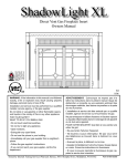
Installation & Operating Manual
The Harman Clarity 929BV Gas Stove
“Ce manuel est disponible en Français sur demande”
R5
SAFETY NOTICE
Please read this entire manual before you install and use your new room heater. Failure
to follow instructions may result in property damage, bodily injury, or even death.
IF THIS HARMAN STOVE IS NOT PROPERLY INSTALLED, A HOUSE FIRE MAY RESULT. FOR YOUR SAFETY, FOLLOW INSTALLATION DIRECTIONS.
CONTACT LOCAL BUILDING OR FIRE OFFICIALS ABOUT RESTRICTIONS AND INSTALLATION INSPECTION
REQUIREMENTS IN YOUR AREA.
Contact your local authority (such as municipal building department, fire department, fire
prevention bureau, etc.) to determine the need for a permit.
Cette guide d'utilisation est disponible en francais. Chez votre concessionnaire de Harman
Stove Company.
WHAT TO DO IF YOU SMELL GAS
• Do not try to light any appliance.
• Do not touch any electrical switch; do not use any phone in your building.
• Immediately call your gas supplier from a neighbor's phone. Follow the gas supplier's
instructions.
• If you cannot reach your gas supplier, call the fire department.
save these instructions.
Table of Contents
INTRODUCTION............................................................ 3
INSTALLATION.............................................................. 4
Clearances.................................................................. 4
Venting........................................................................ 5
Test for Flue Spillage................................................. 5
Assembly.................................................................... 6
Connecting to a Gas Supply....................................... 8
Connecting the Cordset and Thermostat.................... 9
Air Shutter Adjustment............................................. 10
Monitoring the Gas Flame........................................ 10
OPERATION.................................................................. 11
How to Light the Fire............................................... 11
How to Turn Off the Fire.......................................... 11
Lighting Instructions................................................ 11
Maintenance........................................................... 12
Removing the Glass.................................................. 12
Replacing the Gasket................................................ 12
Cleaning the Glass.................................................... 12
Inspecting the Venting.............................................. 12
Cleaning the Logset and Firebox.............................. 12
Wiring Diagram........................................................ 13
PARTS LIST & DRAWING......................................14-15
BURNER MODULE EXPLODED VIEW.....................16
APPENDIX A: FUEL CONVERSION.......................... 17
APPENDIX B: ALTITUDE DE-RATING .................... 18
SPECIFICATIONS ........................................................ 19
WARRANTY..................................................................20
Manufactured by:
Harman Stove Co.
352 Mountain House Road
Halifax, PA 17032
Tested by.
Intertek Testing/Warnock Hersey
8431 Murphy Drive
Middleton, WI 53562
Introduction
Several issues must be addressed when selecting a
suitable location for your Clarity Gas Heater. Observing required clearances to combustible materials, the
proximity to a safe chimney or venting system,and
the accessibility of the gas and electrical supply must
all be considered. In addition, selecting a location that
takes advantage of the building's natural air flow is
also desirable to maximize the heating effectiveness
of the heater. In many cases, this is a central location
within the building.
Adequate combustion and ventilation air must be
provided.
The Harman Clarity 929BV Vented Gas Heater is a
listed gas-fired vented room heater tested by Intertek
Testing/Warnock Hersey to ANSI standard Z21.882002, CSA 2.33-M02, and CAN/CGA-2.17-M91.
The installation of the Clarity Vented Gas Heater
must conform with local codes, or in the absence of
local codes, with the current edition of National Fuel
Gas Code, ANSI Z223.1 — latest edition and CAN
1-B1-149.1 and .2 Installation Code.
The Clarity 929BV is not for use in mobile homes.
CAUTION: This appliance must be vented to the
outside.
Installation and repair of the Clarity Vented Gas
Heater should be done by a qualified service person.
The appliance should be inspected before use and at
least annually by a qualified service person. More frequent cleaning may be required due to excessive lint
from carpeting, bedding material, etc. It is imperative
that control compartments, burners, and circulating air
passageways of the Clarity be kept clean.
When operating your Harman Clarity Gas Heater,
respect basic safety standards. Read these instructions
carefully before you attempt to operate the heater.
Failure to do so may result in damage to property or
personal injury and may void the product warranty.
Consult with your local building code agency and
insurance representative before you begin your installation to ensure compliance with local codes, including
the need for permits and follow-up inspections.
Due to high temperatures, the Clarity Vented Gas
Heater should be located out of traffic and away
from furniture and draperies.
Children and adults should be alerted to the hazards of high surface temperatures and should stay
away to avoid burns or clothing ignition.
Young children should be carefully supervised
when they are in the same room as the Clarity
Vented Gas Heater.
Clothing or other flammable materials should
not be placed on or near the Clarity Vented Gas
Heater.
Clearance from corner of unit to walls
Installation
CLEARANCES
The following clearances to combustibles must be
observed:
Unit to left sidewall
9" (230 mm)
Unit to right sidewall
9" (230 mm)
Unit corner to walls
4" (100 mm)
Rear of unit to back wall
3" (75 mm)
(measured from rear of draft hood to wall)
Unit to alcove ceiling
18" (460 mm)
Maximum alcove depth
14" (355 mm)
Clearance to alcove ceiling
Maximum alcove depth
Sidewall Clearance
In addition to these clearances, adequate accessibility clearance for servicing and proper operation must be
maintained.
Do not in any way obstruct the combustion air inlets
that are located under the heater.
If this appliance is installed directly on carpeting, tile
or other combustible material other than wood flooring the
appliance shall be installed on a metal or wood panel extending at least the full width and depth of the appliance.
Clearance to Back wall
Venting
WARNING: Operation of this heater when not connected to a properly installed and maintained venting
system or tampering with the vent safey shutoff system
can result in carbon monoxide (CO) poisoning and possible death.
The Clarity gas heater is equipped with its own internal
draft hood so no additional external draft hood is required.
The heater should be installed so that the draft hood is in
the same atmospheric pressure zone as the air inlets to the
heater.
Use Only Approved Venting
The Clarity gas heater is tested and listed for connection
to a 4" (100 mm) listed Class B venting system.
If the unit is installed to vent through an approved masonry
chimney or a factory-built chimney system, an approved
Class B chimney liner must be used.
Observe local codes when venting the Clarity. If no local
codes exist, follow the current edition of ANSI Z223.1 and
CAN1- B149 installation codes.
Do not connect the venting to the flue of a chimney that
serves a separate solid-fuel burning appliance.
The venting manufacturer's installation instructions must
be followed exactly.
IMPORTANT: Because of the high efficiency and low
flue gas temperatures of this appliance, it is important that
it be connected to a well-sealed and efficient venting system
which is capable of registering a negative pressure while
the stove is in operation.
The most efficient venting systems are those that have a
minimum number of bends and minimal horizontal runs.
The Clarity gas heater is equipped with a thermally activated vent safety switch that will shut down the main burner
if the heater is not properly venting. The safety switch will
automatically reset after the heater has cooled down.
The switch will continue to cycle off and on until the
venting problem is corrected. If you are unable to correct
the venting problem, seek expert advice from your Harman
dealer or installer.
DO NOT DISCONNECT OR BYPASS THE VENT
SAFETY SWITCH.
Test for Flue Spillage
A spillage test should always be made at the completion
of the installation.
1. Start all exhaust fans in the home and then close all
doors and windows in the room containing the heater.
2. Light the heater and allow it to run for 5 minutes on the
high output setting. If the convection air blower is installed,
it should be turned off for the test.
3. Hold a match or other source of smoke near the draft
hood outlet on the upper back of the stove.
4. If the smoke is not drawn in, turn off the heater and
determine the cause of the lack of draft. If necessary, seek
expert advice.
For sites with swirling or turbulent wind conditions, a
wind cap may solve the problem.
ASSEMBLY
The Clarity is shipped from the factory with the log set
packed inside the firebox. To prepare the stove for installation, the log set must be unpacked, the appropriate burner
system module for either natural gas or propane installed,
and the logs installed.
1
2
Removing the Glass Front
NOTE: The glass front is heavy. Be prepared for its
weight when lifting it to avoid damage during removal.
The wing doors on each side are held closed by magnets.
Push on each door to open it. Loosen the wing nut on each
of the two levers. Grasp each lever and push to the rear to
disengage the front. To keep the levers in the disengaged
position, tighten the wing nuts. Lift the glass front slightly
and remove it from the stove. Set the glass aside in a safe
place where it will not be damaged.
WARNING: Do not abuse the Clarity's glass by
striking, slamming, or similar trauma. Do not operate the Clarity Vented Gas Heater with the glass panel
removed,
3
4
The log set components are shipped from the factory individually wrapped and packed inside the stove. Take them
out of the stove, then carefully remove the wrapping. Handle
the logs gently as they may be damaged easily.
The front is released when
levers on the left and
right sides are pushed to
the rear
cracked or broken. Use only glass supplied by Harman
and approved for use with this heater. Do not use substitute materials. Replacement of the panel should be done
by a licensed or qualified service person.
Remove and Unwrap the Log Set
As shown in the photo above right, the log set consists
of a back log (1), a center log that has a pilot-viewing port
in the left end (2), ember strip (3), and a branch that rests on
top (4).
In addition, there are two side brick panels and a back
brick panel.
Install the Back Log and Back Brick Panel
These two components are installed as a single piece.
Rest the back brick panel on the shelf located on the back
side of the back log, and center it. Holding the two pieces
as a single unit, tilt the top forward slightly and manuever
it over the top of the rear burner—taking care that the top
corners clear the front opening. Place it snugly against the
back wall and center it.
Install the Side Brick Panels
These slide into place along each side and are held by
friction. The notch in each panel faces the back. Install one
side, and then the other.
Install the Ember Strips
The ember strips rest against the front of the firebox and
should fit snugly. Guide them toward you and to the outside
until they fit snugly. Check the air slot in the inside of the
ember strips to confirm that they do not obstruct it.
Install the Center Log
The center log goes all the way to the back and should
be centered. When properly positioned, there should be an
even gap along the front of the center burner in the cavity
in the log. A small portion of the log support frame will be
revealed.
The center log has a round viewing port in the left end
through which the pilot can be observed.
Install the Branch
Orient the branch with the forked end toward the left rear
of the stove and slip it over the two locator pins, one on top
of the back log and the other on the top of the center log.
Secure the Glass Front
NOTE: The glass front is heavy. Lift it carefully to prevent damage. Center the glass on the opening and suspend
it in place by placing the the tab hooks over the top edge
of the opening. Loosen the wing nuts that hold the springloaded levers in place. Press the glass slightly against the
stove to confirm that it seats properly, then press it firmly
against the front while pulling the levers forward to engage
them. Tighten the wing nuts.
The complete log set, with the logs installed and positioned correctly.
CONNECTING THE HEATER
TO A GAS SUPPLY
Natural Gas:
Maximum inlet pressure 7.0" w.c. (1.74 kPa) .
Minimum inlet pressure 5.0" w.c. (1.25 kPa).
Gas manifold pressure 3.5" w.c. (0.87 kPa)
Burn Only the Fuel for which the Heater is Equipped
The Clarity B-Vent will burn either natural gas or propane, but requires a dedicated burner system module for
either fuel. The label on the burner system module indicates
the fuel for which it is equipped. A second label, located near
the rating plate, also indicates the fuel type.
LPG Gas:
Maximum inlet pressure 13" w.c. (3.24 kPa) .
Minimum inlet pressure 11" w.c. (2.74 kPa).
Gas manifold pressure 10" w.c. (2.49 kPa)
DO NOT USE THIS HEATER IF ANY PART HAS
BEEN UNDER WATER OR EXPOSED TO MOISTURE
CORROSION. IMMEDIATELY CALL A QUALlFlED
SERVICE TECHNICIAN TO INSPECT THE HEATER
AND REPLACE ANY PART OF THE CONTROL SYSTEM AND ANY GAS CONTROL WHICH HAS BEEN
UNDER WATER.
NATURAL GAS
PROPANE
RECOMMENDED GAS PIPE DIAMETER
Pipe Length
(Feet)
Making The Connection
The gas inlet is located at the bottom right rear of the stove.
The inlet fitting is a 1/2" female flare flexible pipe.
A separate gas shut-off valve and a 1/8" N.P.T. plugged
tapping should be installed immediately upstream of the
connection to the appliance.
The Clarity B-Vent Gas Heater must be disconnected from
the gas supply piping during any pressure testing of that
system at pressures in excess of 1/2 psig (3.5 kPa).
The Clarity gas control valve must be in the OFF position
during any pressure testing of the gas supply system at pressures equal to or less than 1/2 psig (3.5 kPa).
WARNING: To avoid pipe compounds from entering
into the gas train, apply compounds only to the male pipe
threads and only to the first two threads.
CAUTION: TEST ALL JOINTS FOR LEAKS BEFORE
OPERATING
Schedule 40 Pipe
Inside Diameter
Tubing, Type L
Outside Diameter
N.G.
L.P.
N.G.
L.P.
0-10
1/2"
1.3 cm
3/8"
1.0 cm
1/2"
1.3 cm
3/8"
1.0 cm
10-40
1/2"
1.3 cm
1/2"
1.3 cm
5/8"
1.6 cm
1/2"
1.3 cm
40-100
1/2"
1.3 cm
1/2"
1.3 cm
3/4"
1.6 cm
1/2"
1.3 cm
100-150
3/4"
2.0 cm
1/2"
1.3 cm
7/8"
2.3 cm
3/4"
2.0 cm
NOTE: NEVER USE PLASTIC PIPE. CHECK TO CONFIRM
WHETHER YOUR LOCAL CODES ALLOW COPPER TUBING
OR GALVANIZED PIPE.
Whether or not you have installed a conversion kit, fill
out the installer fuel label, on the stove, or the one that was
included with the conversion kit, and affix it to the stove
in the appropriate location.
Gas Pressure Requirements
Correct gas pressure and the use of a properly sized
gas supply line are essential for the safe and efficient performance of this appliance. Make sure that the plumber or
gas supplier checks the gas supply line and gas pressure at
installation.
NOTE: Improper gas pressure can affect heater performance, flame color, or cause pilot outage.
connecting the CORDSET
The Clarity B-Vent Gas Heater must be installed in accordance with local codes or, in the absence of local codes,
with the most recent edition of the National Electrical Code
ANSI/NFPA 70, or the current Canadian Electrical Code
C22.1.
NOTE: The convection fan requires a 120 VAC supply
for operation, but the heater can be operated without the fan
as in the case of a power outage.
Plug the 3-prong grounded electrical cord plug into
the wall.
Terminal strip for
thermostat connection
Rear view of Clarity
Connecting the
Optional Thermostat
If connecting the optional thermostat, it must be plugged
into the terminal strip located on the left side near the bottom of the stove.
When installing a millivolt control system, use only a special low resistance thermostat..
Do not use a regular heating thermostat.
Be sure that all electrical connections are clean, free
from corrosion, and tight. Inspect connections periodically
to confirm that no corrosion has built up over time.
When properly installed and maintained, a millivolt
control system should give many years of trouble-free
service.
It is important to use wire of a gauge proper for the
length of the wire:
WARNING: This heater is equipped with
a three-pronged grounding plug that
should be plugged directly into a properly grounded receptacle. Do not cut
or remove the grounding prong from
the pluG.
RECOMMENDED WIRE GAUGES
Maximum Length
100'
60'
40'
25'
15'
Wire
Gauge
14
16
18
20
22
AIR SHUTTER ADJUSTMENT
Monitoring the Gas Flame
The final step of the installation is to check the flame
pattern, which should resemble the pattern illustrated in the
right column: The flames should be relatively well-defined
and stable. They should be bright yellow with a blue base
where attached to the burner ports, and should not look
orange or sooty. Start the heater according to the directions on page 11 and
allow the heater to burn for approximately 15 minutes. The
flames will increase in length and become more yellow in
color as the Clarity heats up.
If the flames do not resemble the description above and
the illustration in the right column, the air shutters may be
adjusted.
Three separate screws—one for each burner—are used to
adjust the flames for a particular installation. Two of them
are accessible through the side access port on the right side
of the stove. The third is accessible from the front when the
control door is open. The screws may become hot to the
touch after prolonged operation. Use a 3/16" Allen wrench
to avoid contact if hot. For best results when fine-tuning the
flame picture, initially leave the middle screw unchanged
from its factory setting. Turn the other two screws as needed
to increase or decrease the brightness and length of the flame:
turning counterclockwise will increase the flame; turning
clockwise will decrease the flame.
1. To adjust the rear burner, open the right wing door, reach through the side access port, and turn the rear screw
to adjust flame (see directions above).
2. To adjust the front burner, first open the control door,
then turn the front screw to adjust flame (see directions
above).
Repeat procedure as needed until desired flame effect is
achieved.
Periodically, the flames of the Clarity B-Vent Gas Heater
should be checked while it is operation. The flames should
be relatively well-defined and stable. They should be bright
yellow with a blue base where attached to the burner ports.
The flames should not look orange or sooty. Portions of the
logs will glow red when the flames are properly adjusted.
If you find the flames to be other than that described here,
do not operate the heater. Consult a qualified service person
or your Harman dealer for advice. The Clarity flame pattern will resemble this when the unit is
burning properly.
The properly-burning pilot
will resemble the illustration
to the right.
Rear burner
Center burner
Front burner
10
Air adjustment screws
Operation
HOW TO LIGHT THE FIRE
1. STOP! Read the safety information on the left side
of the panel below.
2. If using the optional thermostat, set thermostat to the
lowest setting.
3. Turn off electric power to the appliance.
4. Turn the ON-OFF/THERMOSTAT switch to the OFF
position.
5. Push in the gas control knob slightly and turn
it clockwise to "OFF." .
NOTE: The knob cannot be
turned from "PILOT" to "OFF"
unless it is pushed in slightly. Do
not force it. 6. Wait five (5) minutes to clear out any gas. If you then
smell gas, STOP! Follow "B" in the safety information on
the label below. If you don't smell gas, go to the next step.
7. Set the High-Low Regulator to High by turning it fully
counterclockwise.
8. Press in the gas control knob slightly and turn counterclockwise to "PILOT."
9. Find the pilot by looking through the round opening
on the left end of the center log.
10. Push the control knob fully down and hold. Immediately push the red piezo ignitor button to light the pilot. It is
normal to have to push the red button several times before
the pilot ignites. Continue to hold the control knob in for
about one (1) minute after the pilot is lit. Release the knob
and it will pop back up. Pilot should remain lit. If it goes
out, repeat steps 5 through 9.
•If the knob does not pop up when released, stop and
immediately call your service technician or gas supplier.
•If the pilot will not stay lit after several tries, turn the
gas control knob to "OFF" and call your service technician
or gas supplier.
11. Turn the gas control knob counterclockwise to
"ON."
12. Place the ON-OFF/THERMOSTAT switch in the ON
position or in the THERMOSTAT position if the optional
thermostat is used.
13. Turn on the electric power to the heater.
14. Set the optional thermostat to the desired room temperature.
15. Set the High-Low Regulator to desired setting: turn
fully counterclockwise for High and fully clockwise for
Low.
NOTE: An odor resulting from the initial heating of new
materials in your heater is not unusual during the first fire,
and in most cases will disappear after an hour or two.
HOW TO TURN OFF THE FIRE
1. If using optional thermostat, set thermostat to the lowest position.
2. Turn off the electric power to the appliance.
3. Turn the ON-OFF/THERMOSTAT switch to the OFF
position.
4. Push in the gas control knob slightly and turn it clockwise to “OFF.”
NOTE: The knob cannot be turned from “PILOT” to
“OFF” unless it is pushed in slightly. Do not force it.
11
Maintenance
Cleaning the Log Set and Firebox
During the annual inspection and maintenance appointment, the service person should clean dust, lint, and any
light accumulation from the logs and the firebox area.
An extra-soft brush should be used on the logs as they
are extremely fragile; a vacuum cleaner may be used on
the firebox. If at any time the logs cannot be removed or
installed without forcing, the cause must be found. The
logs must never be forced.
A qualified service person recommended by your
Harman dealer should conduct an annual inspection and
maintenance of your Clarity, its venting, and the installation to keep it running safely and efficiently. These procedures should be performed only by a qualified service
person. The gas supply should be turned off whenever a
maintenance procedure is performed.
If the front panel, side doors, or front access door are
removed for servicing, they must be replaced prior to
operating the Clarity.
Removing the Front
See directions on page 6.
Removal and Re-installation of the Log Set for Cleaning
CAUTION: The ceramic logs are durable when
handled and installed properly. However, they are delicate and may be damaged easily if not handled with care.
Handling damage to the ceramic logs is not covered by
warranty.
DO NOT HANDLE LOGS WHILE THEY ARE
HOT. ALLOW PLENTY OF TIME FOR THE STOVE
TO COOL COMPLETELY BEFORE HANLDING.
Removing the Glass Front
for Replacement
Refer to page 6 for directions on removing the glass
front. Use only authorized Harman replacement glass
components available from your dealer.
Replacing the Gasket
The Clarity has 5/8" diameter fiberglass gasket in the
front door. Should it ever need replacement, use only the
proper replacement gasket that is available from your
Harman dealer. To replace the gasket, follow this procedure.
1. Open the door
2. Remove the existing gasket and clean its channel
with a scraper or wire brush.
3. Lay a thin bead of high temperature silicone the
entire length of the channel.
4. Lay the gasket in the channel with sufficient pressure
that is stays in place.
5. Trim the excess from the end of the gasket so that it
butts snugly against the other end without leaving a gap.
Seal the end joint with high temperature silicone.
6. Close the door and apply firm pressure to seat the
gasket evenly throughout.
Remove the Branch
Detach the branch from the two locator pins and remove it. Brush it gently and carefully place it to one side.
Remove the Center Log
Lift the center log and remove it. Brush it gently and
carefully place it to one side with the branch.
Remove the Ember Strips
Carefully remove the ember strips, clean them, and
place them with the other logs.
Remove the Side Brick Panels
Carefully remove first one side panel, and then the
other. Clean and place to side.
Remove the Back Log and Back Brick Panel
Finally, carefully remove these two components as a single piece. Brush them gently and place them to the side.
Finish the procedure by vacuuming the interior of the
firebox, then re-install the logs and secure the glass front
following the procedures on page 7.
Cleaning the Glass
The glass may be cleaned with ordinary household
glass cleaner and a soft cloth or paper towel.
WARNING: Never clean the glass when it is hot. Do
not use abrasive cleaners on the glass.
Inspecting the Venting
An inspection of the venting system should be made
during the annual service appointment. The system must
have no blockage and must be in good repair. The vent
manufacturer's instructions may provide specific suggestions or details on vent inspection. Any sections that are
taken apart for the inspection must be reassembled and
sealed as required.
12
The Clarity B-Vent gas heater, when installed, must be electrically grounded in accordance with local codes or, in the absence
of local codes, with the current edition of the National Electrical Code, ANSI/NFPA 70 in the United States or the current
Canadian Electrical Code CSA 22.1 in Canada.
13
Parts List
The following replacement parts for your Harman Clarity B-Vent are available from your Harman dealer.
ID#
1
2
3
4
5
6
7
8
9
10
11
12
13
14
15
16
17
18
19
20
21
22
23
24
25
26
27
28
29
30
31
32
33
34
35
36
37
38
Part No.
1-89-08270
1-10-08262-1
1-10-08262-2
3-40-08286
3-40-08235
3-40-08236
3-40-08237
3-40-08401
3-40-08232
3-40-08233
3-40-08234
3-40-08224
3-40-08225
3-40-08226
3-31-965487
3-40-00141
3-31-08225
3-20-408412
2-00-4213
3-20-326004
2-00-4177
3-42-2312
3-44-1086405
3-43-4103
3-40-120
3-40-121
1-10-08285
3-44-08278
3-40-820628
3-40-82057
3-40-57356
3-40-64347
3-40-64739
3-40-57271
3-40-57753
3-40-57753
3-40-08231
3-40-08229
Part
BVG weldment
Left wing door
Right wing door
1/2" gas inlet flex
Rear log
Front log
Top log
Ember strip
Left brick panel
Right brick panel
Rear brick panel
Front burner tube
Center burner tube
Rear burner tube
Ext. spring
Formed wire gold trim
Magnet
Snap disc fan control
Snap disc fan control bracket
Power cord
Lower rear access cover
Glass gasket
5/8" tight knit rope for door
Gold plated door frame
13-3/4" X 19" glass
5-3/4" X 13-3/4" glass
Distribution blower w/ends
Pilot tower gasket
NG valve
LP valve
#56 orifice, LP front/NG center
#47 orifice, NG front
#39 orifice, NG rear
#71 orifice, LP center
#53 orifice, LP rear
#53 orifice, LP rear
Piezo cable
Pilot, NG
39
40
41
42
43
44
45
46
47
3-40-08230
3-40-08228
3-40-08220
3-31-08282
3-31-08283
3-31-08284
3-30-310056082
3-20-326006
3-20-326005
48 3-20-08221
49 3-20-08219
50 2-00-08281
51 0-46-250
52 1-00-08513
53 1-00-08314
54 3-20-408411
55 2-00-42208
56a 2-00-42220
56b 2-00-42219
57 2-00-4169
58 1-10-08265-1
59a 1-10-08265-2
60a 2-00-4138-1
60b 2-00-4138-2
61 1-10-08287
62 1-10-08258
63 2-00-42217
64 2-00-4162
65 2-00-4210
66 2-00-4172
14
Pilot, LP
Thermocouple
Piezo ignitor
90° brass elbow
1/4" tp 3/8" male compression fitting
3/8" tp 3/8" male compression fitting
BHSCS 5mm X 8mm for valve
18" valve harness
Harness w/VSC
On-Off rocker switch
Thermopile
3/8" tubing
1/4" tubing
Valve change-over assembly, NG
Valve change-over assembly, LP
Snap disc safety switch
Rear cover
Snap disc safety switch bracket
Snap disc safety switch heat shield
Base trim
Latch arm, left
Latch arm, right
Latch cam, left
Latch cam, right
Front door assembly
Top
Draft hood heat shield
Control door
Control heat shield
Baffle
Clarity B-Vent - Exploded View
15
Clarity Burner Module - Exploded View
38
49
40
37
14
13
12
52
33
41
31
51
50
43
44
48
16
32
42
Appendix A
Step 3: Using a small flat-blade screwdriver, remove
the three screws that hold the LP knob module in place.
Remove the module and replace it with the Natural Gas
module from the kit. See kit instructions.
Step 4: Affix the conversion label to the valve so that any
future service tech etc... can plainly see that the valve was
converted.
Step 5: Mark the appropriate fuel box on the unit label
using a permanent marker.
Step 6: Affix the Installer Fuel Label in place of the existing one.
Converting the CLARITY B-Vent from
One Gas to Another in the Field
NOTE: THE CONVERSION SHALL BE CARRIED OUT IN ACCORDANCE WITH THE REQUIREMENTS OF THE PROVINCIAL OR LOCAL
AUTHORITIES HAVING JURISDICTION AND IN
ACCORDANCE WITH REQUIREMENTS OF THE
CURRENT EDITION OF THE NATIONAL FUEL GAS
CODE, ANSI Z223.1 or the CAN/CGA-B149 INSTALLATION CODES.
Important: Perform a leak test upon completion
of the fuel conversion.
Conversion Kit Components
*1 Pilot Orifice
*2 Burner Orifices
* Regulator Assembly
* Conversion Instructions
* Installer Fuel Label
* Conversion Label-Must be
attached to valve upon completion.
NATURAL GAS
PROPANE
Steps For Completing The Fuel Conversion.
Prior to installing the fuel conversion, remove the Glass
door and the log set, to gain access to the burner module.
Remove the burner tubes by sliding to the left while lifting upward. Remove the burner cover plate and the tube
box top.
Step 1: Remove pilot hood with a 7/16” wrench. Inside,
you will find and discard the Propane orifice. Install the
new Natural Gas orifice from the kit. Tighten the pilot
hood and assure proper alignment of the directional openings.
Step 2: Using a 1/2 in. deep-well socket, remove the
three main burner orifices. Install the new orifices accordingly; Front = #47, Middle = #56, Rear = #39. Notice
the #56 that you removed from the front will be used in
the middle for Natural Gas. Apply a thread sealer to the
orifices prior to installing.
CAUTION: LABEL ALL WIRES PRIOR TO DISCONNECTION WHEN SERVICING CONTROLS. WIRING ERRORS
CAN CAUSE IMPROPER AND DANGEROUS OPERATION.
VERIFY PROPER OPERATION AFTER SERVICING.
SEE WIRING DIAGRAM ON PAGE 13.
17
Appendix B
De-rating for High Altitude
For U.S. installations, the Clarity B-Vent is approved
for elevations up to 2000 feet using the factory-installed
burner injectors. At elevations above 2000 feet, U.S. codes
require a decrease in the input rating by changing the burner
injectors to a smaller size. The chart below lists by part
numbers the appropriate injectors for both LP and natural
gas at various altitudes.
For Canadian installations, the Clarity B-Vent is approved for elevations up to 610 meters (2000 feet). For
installations from 610-1370 meters (2000-4500 ft.) the
orifice sizes (DMS) for natural and propane gas are as
shown in the chart below.
natural gas
Front
Altitude
Injector
0-2000'
47
2000-3000'
48
3000-4000'
49
4000-5000'
49
5000-6000'
50
6000-7000'
50
7000-8000'
51
8000-9000'
51
PROPANE
Front
Altitude
Injector
0-2000'
56
2000-3000'
56
3000-4000'
56
4000-5000'
57
5000-6000'
57
6000-7000'
57
7000-8000'
58
8000-9000'
58
For high altitude installations consult the local gas distributor or the authority having jurisdiction for proper rating
methods.
NOTE: The difference in altitude derating requirements
for the U.S. and Canada is simply a result of differences in
testing standards between the two countries.
If the installer must convert the unit to adjust for varying
altitudes, an information sticker like the one below must be
filled out and affixed to the appliance at the time of conversion.
Harman
Part No.
3-40-64347
MALE
MALE
MALE
MALE
MALE
MALE
MALE
Center
Injector
56
56
56
57
57
57
58
58
Harman Part No.
3-40-57356
3-40-57356
3-40-57356
MALE
MALE
MALE
MALE
MALE
Rear
Injector
39
40
41
42
42
43
43
44
HarmanNominal Btu
Part No.
Input Rate
3-40-64739
40,000
MALE
38,400
MALE
36,900
MALE
35,400
MALE
34,000
MALE
32,600
MALE
31,300
MALE
30,100
Harman
Part No.
3-40-57356
3-40-57356
3-40-57356
MALE
MALE
MALE
MALE
MALE
Center
Injector
71
71
71
71
71
71
71
71
Harman Part No.
3-40-57271
3-40-57271
3-40-57271
3-40-57271
3-40-57271
3-40-57271
3-40-57271
3-40-57271
Rear
Injector
53
54
54
54
55
55
56
56
Harman Nominal Btu
Part No.
Input Rate
3-40-57753
40,000
MALE
36,900
MALE
36,900
MALE
35,400
MALE
32,600
MALE
32,600
3-40-57356
30,100
3-40-57356
30,100
●When ordering injectors that have no Harman
Part number, specify MALE or FEMALE and
the appropriate 2- digit number.
THE CONVERSION SHALL BE CARRIED OUT
BY A MANUFACTURER'S AUTHORIZED REPRESENTATIVE IN ACCORDANCE WITH THE
REQUIREMENTS OF THE MANUFACTURER,
PROVINCIAL OR TERRITORIAL AUTHORITIES
HAVING JURISDICTION AND IN ACCORDANCE
WITH THE REQUIREMENTS OF THE CURRENT
EDITION OF CAN/CGA-B141.1 OR CAN/CGAB141.2 INSTALLATION CODES.
This appliance has been converted for use at an altitude of __________ft.
Orifice Sizes: Front ________
Center_________
Rear ________
Input (Btu/hr) _________________
Manifold Pressure __________________
Fuel Type _______________________
Converted By _________________________________
Date of Conversion _______________________________
18
Clarity B Vent .
Gas Heater Specifications
Tested to ANSI Z21.88-2002, CSA 2.33-M02, CAN/CGA 2.17-M91.
NATURAL GAS
Input Rating (Btu/hr) (0-1375 m)
Min. Input Rating (Btu/hr) (0-1375 m)
Injector Sizes (DMS) (front/center/rear (0-1375 m)
Manifold Pressure (in w.c./kPa) Minimum Manifold Pressure (in w.c./kPa) Minimum Inlet Pressure (in w.c./kPa) Maximum Output (Btu/hr) (0-1375 m) AFUE (seasonal efficiency; minimum venting)
Steady State Efficiency (max. input, blower on High)
40,000
27,000
47/56/39
3.5/0.87
1.7/0.42
5.0/1.25
30,500
65.2%
78.2%
MINIMUM CLEARANCES FROM COMBUSTIBLE CONSTRUCTION
Unit to left sidewall
9 in. (230 mm)
Unit to right sidewall
9 in. (230 mm)
Unit corner to walls
4 in. (100 mm)
Rear of unit to back wall 3 in. (75 mm) .
(measured from rear of draft hood heat shield)
Unit to alcove ceiling
18 in. (460 mm)
Maximum alcove depth
14 in. (355 mm)
Electrical Rating: 120 Volts, 60 Hz., Less than 1 Amp
Stove Weight: 234 lbs.
19
PROPANE
40,000
28,000
56/71/53
10.0/2.49
5.9/1.47
11.0/2.74
30,800
66.0%
79.7% .
HARMAN GOLD WARRANTY
6 YEAR TRANSFERABLE LIMITED
WARRANTY (Residential)
1 YEAR LIMITED WARRANTY (Commercial)
Harman Stove Company warrants its products to be free from defects in material or workmanship, in normal use and service, for a period of 6 years from the date of sales invoice and for mechanical and electrical failures, in normal use and service,
for a period of 3 years from the date of sales invoice.
If defective in material or workmanship, during the warranty period, Harman Stove Company will, at its option, repair or
replace the product as described below.
The warranty above constitutes the entire warranty with respect to Harman Stove Company products. HARMAN STOVE
COMPANY MAKES NO OTHER WARRANTY, EXPRESSED OR IMPLIED, INCLUDING “ANY” WARRANTY OF MERCHANTABILITY, OR WARRANTY OF FITNESS FOR A PARTICULAR PURPOSE. No employee, agent,
dealer, or other person is authorized to give any warranty on behalf of Harman Stove Company. This warranty does not apply
if the product has been altered in any way after leaving the factory. Harman Stove Company and its agents assume no liability
for “resultant damages of any kind” arising from the use of its products. In addition, the manufacturer and its warranty administrator shall be held free and harmless from liability from damage to property related to the operation, proper or improper, of
the equipment.
THERE ARE NO WARRANTIES WHICH EXTEND BEYOND THE DESCRIPTION ON THE FACE HEREOF.
THESE WARRANTIES APPLY only if the device is installed and operated as recommended in the user’s manual.
THESE WARRANTIES WILL NOT APPLY if abuse, accident, improper installation, negligence, or use beyond rated
capacity causes damage.
HOW TO MAKE A CLAIM - Any claim under this warranty should be made to the dealer from whom this appliance
was purchased. Then contact is made with manufacturer, giving the model and serial numbers, the date of purchase, your
dealer’s name and address, plus a simple explanation of the nature of the defect. Extra costs such as mileage and overtime are
not covered. Nuisance calls are not covered by these warranties.
THIS WARRANTY IS LIMITED TO DEFECTIVE PARTS - REPAIR AND/OR REPLACEMENT AT HARMAN STOVE COMPANY’S OPTION AND EXCLUDES ANY INCIDENTAL AND CONSEQUENTIAL DAMAGES CONNECTED THEREWITH.
WARRANTY EXCLUSIONS: Failure due, but not limited to, fire, lightning, acts of God, power failures and/or surges,
rust, corrosion and venting problems are not covered. Damage and/or repairs including but not limited to; remote controls,
filters, fuses, knobs, glass, ceramic brick panels, ceramic fiber afterburners, door packing, tile, ceramic log sets, paint, batteries
or battery back-up and related duct work are not covered. Also excluded from this warranty are consumable or normal wear
items including but not limited to; flame guides, grates, coal bars, afterburner hoods, fire brick, gaskets. Additional exclusions
for corn stoves are burnpot housing weldment, burnpot grate weldment (pellet or corn), burnpot front plate (pellet or corn),
burnpot front plate lock, corn auger extension, ceramic insert, and ceramic insert plate. Additional or unusual utility bills incurred
due to any malfunction or defect in equipment and the labor cost of gaining access to or removal of a unit that requires special
tools or equipment are not covered. Maintenance needed to keep the stove in “good operating condition” is not covered. This
includes, but is not limited to, cleaning, adjustment of customer controls and customer education. Labor, materials, expenses
and/or equipment needed to comply with law and/or regulations set forth by any governmental agencies are not covered.
This Warranty provides specific legal rights and the consumer may have other rights that vary from state to state.
In the event of change in ownership, the remaining portion of this warranty may be transferred to the new owner by sending the new owner information and a transfer fee of $25.00 US to the Harman Stove Company.
PLEASE READ THE LITERATURE BY THE MANUFACTURER FOR THE VARIOUS ACCESSORY DEVICES. THE MANUFACTURER WARRANTS THESE ACCESSORY DEVICES, NOT HARMAN STOVE COMPANY OR THEIR WARRANTY ADMINISTRATOR. FURTHERMORE, THESE ACCESSORY DEVICES MUST BE INSTALLED AND USED ACCORDING TO THE RECOMMENDATIONS OF THE MANUFACTURER.
REMEDIES - The remedies set forth herein are exclusive and the liability of seller with respect to any contract or sale
or anything done in connection therewith, whether in Contract, in tort, under any warranty, or otherwise, shall not, except as
herein expressly provided, exceed the price of the equipment or part of which such liability is based.
CLARIFY - The above represents the complete warranty, which is given in connection with stoves, manufactured by Harman
Stove Company. No other commitments, verbal or otherwise, shall apply except by a written addendum to this warranty.
20