1
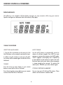
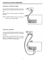
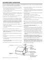
QSR1000
AM/FM STEREO RECEIVER
INSTRUCTIONAL MANUAL
FEDERAL COMMUNICATIONS COMMISSION (FCC) INFORMATION
This device generates and uses radio frequency (RF) energy, and if not installed and used properly, this
equipment may cause interference to radio and television reception.
If this equipment does cause interference to radio or television reception (which you can determine by turning the equipment off and on), try to correct the interference by one or more of the following measures:
• Reorient the receiving antenna (that is, the antenna for a radio or television that is “receiving” the
interference).
• Move the unit away from the equipment that is receiving interference.
• Plug the unit into a different wall outlet so that the unit and the equipment receiving interference are on
different branch circuits.
FOR YOUR SAFETY
The AC power plug is polarized (one blade is wider than the other) and only fits into
AC power outlets one way. If the plug won’t go into the outlet completely, turn the plug
over and try to insert it the other way. If it still won’t fit, contact a qualified electrician
to change the outlet, or use a different one.
Do not attempt to bypass this safety feature.
CAUTION: TO PREVENT ELECTRIC SHOCK, MATCH WIDE BLADE OF PLUG TO WIDE SLOT,
FULLY INSERT.
FOR YOUR RECORDS
In the event that service should be required, you may need both the model number and the serial number.
In the space below, record the date and place of purchase, and the serial number:
Model No.
Remote Control No.
Date of Purchase
Place of Purchase
Serial No.
SERVICE INFORMATION
This product should be serviced only by those specially trained in appropriate servicing techniques. For
instructions on how to obtain service, refer to the warranty included in this manual.
2
FIRST THING FIRST
UNPACK THE RECEIVER..........................................................................................................4
BASIC CONNECTIONS.......................................................................................................................4
SYSTEM SETUP.........................................................................................................................5
CONNECTING THE WIRES................................................................................................................5
CONNECTING THE MAIN SPEAKERS.................................................................................................5
CONNECTING THE ANTENNAS........................................................................................................5
CONNECTING FOR POWER....................................................................................................6
USING HEADPHONES.............................................................................................................6
RECEIVER CONTROLS & OPERATIONS
GENERAL CONTROLS..............................................................................................................7
DISPLAY MESSAGES.................................................................................................................8
TUNING THE RECEIVER...........................................................................................................8
TO STORE STATION...........................................................................................................................9
TO PLAY PRESET STATION..................................................................................................................9
PRESET SCANNING...........................................................................................................................9
TUNER-30 PRESET SCAN...................................................................................................................9
SELECT PRESET MEMORY...................................................................................................................9
CONNECTING AUXILIARY COMPONENTS
BEFORE YOU CONNECT........................................................................................................10
CONNECTING A COMPACT DISC.........................................................................................11
CONNECTING A TAPE DECK.................................................................................................11
USING THE REMOTE CONTROL
BATTERY INSTALLATION........................................................................................................12
BASIC CONTROLS.................................................................................................................12
CARE AND MAINTENANCE
TROUBLESHOOTING TIPS......................................................................................................13
RECEIVER/TUNER OPERATION........................................................................................................13
REMOTE CONTROL OPERATION......................................................................................................13
GENERAL........................................................................................................................................13
CLEANING THE EXTERIOR...............................................................................................................13
EQUIPMENT SPECIFICATIONS................................................................14
LIMITED WARRANTY.......................................................................................15
3
FIRST THINGS FIRST
UNPACK THE RECEIVER
Unpack the receiver and locate all the accessories.
You should have:
•
•
•
•
•
one
one
one
one
one
receiver unit
remote control
external, detachable FM T-type antenna
external AM loop antenna
instruction book
BASIC CONNECTIONS
Assuming you have a VCR, the following steps
will help you quickly set up your new receiver.
If you have more electronic components, consult the
table of contents or index for the page on which to
find the connection description that best suits your
situation.
*The wires and jacks have been color-coded to
assist you .
1. Using an audio wire with red and white connectors, connect the audio OUT jack on the
back of your stereo VCR to the audio "IN" jack under
the VCR heading on the back of the receiver.
2. Using the video cable with yellow connectors,
connect the video "OUT" jack on the back of your
VCR to the "VIDEO IN" or "VIDEO INPUT" on the
back of your TV. If there are multiple video jacks on
the back of your TV, use "VIDEO 1."
4
FIRST THINGS FIRST
SYSTEM SETUP
CONNECTING THE WIRES
Each speaker -the two main, -has a designated set of terminals
on the back panel of the central unit.
Uncoil the speaker wires and locate the bare ends. Press and
hold down on the tab to open the red terminal, then insert the red
(+) wire. Release hold to close tab. Use the same procedure for
the black (-) wire into black terminal.
WARNING: Be sure to follow these instructions carefully. The
system can be damaged if speakers are improperly connected.
CONNECTING THE MAIN SPEAKERS
The two main speakers should be set between 6 and 10 feet apart. Putting the speakers any closer or any
farther apart may result in distorted sound.
The speakers should also form a 45 degree angle to the central listening point in the room, creating a triangle of listening enjoyment.
CONNECTING THE ANTENNAS
The AM and FM antennas connect to the AM and FM terminals
on the system's back panel.They must be hooked up for you to
receive clear reception.
Uncoil the antenna wires and locate the bare ends. Press down
on the tab to open the terminal and insert the wire. Snap the tab
closed. After connecting the antennas, extend them to their full
length and adjust their positioning for better reception.
Sit Back and Listen...
Fine tuning is best performed with the remote
control so that adjustments can be made from
the viewing or listening area.
5
FIRST THINGS FIRST
CONNECTING FOR POWER
Make sure you connect all your other electronic components and your
speakers before plugging your receiver into the outlet.
Plug the power cord in the wall outlet, matching the wide blade of the
plug with the wide slot in the outlet. Be sure to insert the plug
completely.
USING HEADPHONES
To listen privately through your audio system, use the PHONES jack to the right of the volume dial
on the receiver.
NOTE: Headphones are not included.
Have a blast - Just not in your ears!
Make sure you turn down the volume before you put
on the headphones. Increase the volume to the desired
level after headphones are in place.
6
RECEIVER CONTROLS & OPERATIONS
GENERAL CONTROLS
POWER STAND BY/ON
BALANCE
The POWER STANDBY/ON button activates or
deactivates the system. When the system is activated, the unit will default to the last mode it was in
before power was removed.
The BALANCE dial allows you to manually adjust
the balance of sound coming from your speakers.
BASS
TUNING DOWN/UP
The BASS dial allows-you to manually adjust the
amount of bass the unit emits.
The TUNING DOWN/UP buttons allow you to scan
the active frequency for the radio station of your
choice.
TREBLE
The TREBLE dial allows you to manually adjust the
amount of treble the unit emits.
SPEAKERS
FUNCTION BUTTONS
The SPEAKERS button allows you to turn ON or
OFF the speakers.
The function buttons include CD, TAPE,
SCAN FM, AM,TV, VCR,VIDEO.
PRESET SCAN
PRESET
MASTER VOLUME
The PRESET SCAN button allows you easy access
for up to 30 preset radio stations.
The Master Volume dial allows you to adjust the
level of audio output.
AUTO
PHONES
The AUTO button allows you to select
auto or manual tuning.
The receiver has been equipped with a Phone jack.
Plug your headphones - not included - into the jack
and listen to your favorite media in private.
7
RECEIVER CONTROLS & OPERATIONS
DISPLAY MESSAGES
The following is an example of all the display messages you may encounter while using your receiver.
Specific messages are referenced within the section(s) they apply.
TUNING THE RECEIVER
SELECT THE AM/FM BAND
AUTO TUNING
1. Push the FM or AM button on the receiver (or the
AM-FM button on the remote) to activate the tuner.
Use the AUTO feature to automatically search for
stations of sufficient strength. Press AUTO on your
receiver or remote to the receiver into AUTO mode.
"AUTO" appears in the display. Press TUNING up
or down button on the receiver to search. The tuner
finds and stops on the next station whose frequency
is strong enough to be received. To continue the
search, press TUNING up or down button again.
2. When using the remote you must press the AMFM button on the remote again to select the FM or
AM band.
TUNING
Press the tuning up arrow button on your remote
button to move up the AM or FM band.
STORING STATIONS IN MEMORY
Press the tuning down arrow button on your remote
to move down the AM or FM bancd.
You can store up to 30 AM and FM stations. These
stations can be stored in random order.
8
RECEIVER CONTROLS & OPERATIONS
TO STORE A STATION
TUNER-30 PRESET SCAN
1. Press the FM or AM button on the receiver (or the
AM-FM button on the remote).
SELECT PRESET
2. Select the station you want to store in memory
using the methods described above.
1. Select 1-5 Preset Station
• You can select the 1-5 preset scan directly & use
SHIFT key for 6-30
3. Press the MEMORY button on the remote
until "MEMORY" blinks in the display. While
"MEMORY" is blinking, press number buttons on
the remote for the station.
2. Select 6-10 Preset Station
• Press the SHIFT KEY once and the diplay change
from 1-5 to 6-10 you can then select 6-10 as
you like.
3. Select 11-30 Preset Station
• By pressing the SHIFT KEY two times, the display
changes from 1-5 to 11-15, and you can get the
11-15 preset stations.
• You can get the 16-30 or back to 1-5 by pressing
the SHIFT KEY repeatedly.
If the Memory indicator on the display turns off
before you preset your station selection, press
MEMORY again.
TO PLAY PRESET STATION
Press the appropriate Preset Station number.
PRESET SCANNING
Use the SCAN button on the receiver's front panel
to review the preset stations stored in the tuner's
memory. "PRESET" and the station's location in
memory appear in the display. The tuner automatically scans all preset stations in order, pausing at
each one for approximately 5 seconds.
SELECT PRESET MEMORY
The method for memory is the same as preset, to
memory, you need to press and hold the NUMBER
key for 2 a few seconds.
When the tuner reaches the station you want. Press
SCAN to stop the scanning. If the scan is not interrupted, the tuner reviews all preset stations in order,
stopping at the point where the scan began.
9
CONNECTING AUXILARY COMPONENTS
BEFORE YOU CONNECT..
CONNECTING THE CABLES
• Protect components from power surges.
• Try not to coil any power cables and keep them
away from the audio/video cables as much as
possible.
• Connect all components before plugging power
cords into the wall outIet.
• Make sure all antennas and cables are properly
grounded. Refer to the Safety Tips sheet packed
with your receiver.
• Always turns off the receiver and/or components
before you connect or disconnect any cables.
• Always make sure the color - coded plugs match
the color of the terminals in which they are
inserted.
PROTECT YOUR COMPONENTS FROM
OVERHEATING
• The connection cable plugs and jacks are color
coded as follows:
• Do not block ventilation holes in any component.
Arrange the components so that air can circulate
freely.
- Speaker Terminals Red for positive (+) terminals.
Black for negative (-) terminals.
• Do not stack components directly on top of each
other.
- Some units may be supplied with connection
plugs that are color - coded Red and Black
instead of Red and White. In this case, the
Black plug takes the place of the White plug.
• AlIow adequate ventilation when placing your
components in a stand.
• place an amplifier near the top shelf of the stand
so heating air rising from it will not flow around
other components. If you have a satellite receiver,
you shouId place it on the topshelf.
POSITION CABLES CORRECTLY TO AVOID AUDIO
HUM OR INTERFERENCE
• Insert all cable plugs firmly into their jacks.
• Place audio/video cables to the sides of the
receiver's back panel instead of straight down the
middle after you connect the components.
10
CONNECTING AUXILARY COMPONENTS
CONNECTING A COMPACT DISC PLAYER
Using one paired (red/white) stereo cable, connect your
new receiver to your compact disc player as shown to the
right.
To play a CD, press CD, put the receiver in CD mode and
press PLAY.
NOTE: The AUDIO SOURCE connection can be used as
input for any stereo audio signal.
CONNECTING A TAPE DECK
Using two paired (red/white) stereo cables, connect your
new receiver to your tape deck as shown in the diagram
to the right.
To play a tape, press TAPE and then PLAY. To record a
tape, turn on the audio source you want to record from
and then press RECORD on the tape player.
11
USING THE REMOTE CONTROL
BATTERY INSTALLATION
The remote control operates on two batteries. Install
them before attempting to operate the remote.
1. Slide the battery compartment cover off the back of
the remote.
2. Insert 2 AAA batteries, matching the + and - ends
of each battery with the symbols in the compartment.
3. Replace the cover.
BASIC CONTROLS
To use the remote control effectively, always aim it
directly at your receiver.
POWER turns the AM/FM receiver OFF or ON.
VOLUME UP and DOWN increases or decreases the
volume.
MUTE turns off the receiver's sound, Press again to
restore the sound.
RECEIVER CONTROLS
AM-FM activates the tuner and toggles between the
AM band and the FM band.
RECEIVER/TUNER CONTROLS
The Tuning Up Arrow lets you manually move up the
AM/FM band.
AUTO selects auto tuning.
MEMORY stores the selected station in the receiver's
memory.
NUMBER BUTTONS let you enter numbers when
needed.
The Tuning Down Arrow lets you manually
move down the AM/FM band.
12
CARE AND MAINTENANCE
TROUBLESHOOTING TIPS
RECEIVER/TUNER OPERATION
GENERAL
STEREO indicator is off.
No audio.
• Adjust the antenna.
• Make sure the MUTE inclicator on the front
panel is off.
• The signal is too weak. Connect an external
antenna
• Make sure the speakers are turned on.
• The signal is Mono
• Check the connections.
• Severe hum or noise
• Check the power cord connection. No audio
from one channel.
• The signal is too weak. Connect an external
antenna
• Adjust the balance control.
• Check the speaker wire connection or connecting cable.
• Adjust the antenna
REMOTE CONTROL OPERATION
The remote control does not operate the unit
• Noise when the TV is turned on. TheTV is to
close to the audio system.
• Another function is selected on the remote. Press
the correct function button
• Check the connection between the receiver and
the speaker. The sound does not match the video.
• No batteries installed. Install the batteries before
attempting to operate the remote. Be sure to
match the + and - ends of each battery to the
symbols shown in the remote battery compartment
• Press the function button for the video source.
CLEANING THE EXTERIOR
Disconnect the system from AC power before cleaning the exterior of the system with a soft dust cloth.
• The batteries are exhausted. Replace all batteries
• The remote is not pointed at the remote control
sensor on the main unit or there is an obstacle
between the remote and the main unit
• The remote control is to far from the main unit
• Move closer
13
EQUIPMENT SPECIFICATIONS
AMPLIFIER SECTION
Left & Right Channel: 100Watts 1% THD @ 1KHz
Muting Attenuation: 90 dB
Frequency Response: 80 - 10 KHz +/- 3 dB
AM TUNER SECTION
Frequency Response: 8OHz - 2.3KHz +/- 6 clB
Usable Sensitiivity: 800 uV/m @: S/N 20 dB
Signal to Noise: 38 dB
Image Ratio: 30 dB ~ 1000 KHz
IF Rejection: 40 dB
FM TUNER SECTION
Frequency Response: 40 Hz - 1 5 KHz +/- 3 dB
Quieting: 24 dBu
Signal to Noise: 60 dB (stereo)/6.5 dB (mono)
Image Ratio: 40 dB
IF Rejection: 65 dB
Specifications are based on nominal measurements.
14
LIMITED WARRANTY
Quest warrants this product to be free from manufacturing defects in material and workmanship under
normal use for a period of 1 year from date of purchase, if service is required during the first year of
ownership, product should de returned to the store where it was purchased with the original receipt for an
exchange.
This warranty does not apply to any Quest product which is used for commercial, rental, or industrial
purpose, is damaged by accident, misuse, abuse, improper line voltage water lightning, or any acts of God.
This warranty is void if product is altered, modified, or if any parts of service covered by this warranty are
furnished by anyone other than Quest. This warranty does not cover cartons, carrying case, batteries,
cosmetic parts, broken or marred cabinets, magnetic tapes, compact discs, or any other accessories used
in connection with the product or consequential damages due to defect in the product.
This warranty is not transferable and only applies to the original purchase. Any implied warranties,
including the warranty of merchants, are limited in duration to the period of this expressed warranty and
no warranty whether express or implied shall apply to the product thereafter. Under no circumstance shall
Quest be liable for any loss or consequential damage arising out of the use of this product.
21000 TransCanada • Baie D’Urfé • Qc • Canada • H9X 4B7
Tel.: (514) 457-2555 • Fax: (514) 457-0055
Toll Free Order Number: 1-800-567-3275 • Toll Free Fax Number : 1-866-457-5507
15
IMPORTANT SAFETY INSTRUCTIONS
Some of the following information may not apply to your particular product; however, as with any electronic product,
precautions should be observed during hanlding and use.
•
Before using the product, please follow and adhere to all warnings,
safety and operating instructions located on the product and in the user
book. Save all instructions for future reference.
• Do not expose product to rain and do not use near water; such as, sink,
wet basement, swimming pools, etc.
• Always leave sufficient space around the product for ventilaton. Do not
place product or on a bed, rug, in a bookcase or cabinet that may
prevent air flow through the vent openings.
• Do not expose product to extreme temperatures such as found near a hot
radiator or stove, or in a car parked in the Summer sun.
• Connect power cord only to AC power source as marked on the product.
• Some products employ a polarized AC line plug (one blade is wider). This
is a safety feature. The plug will go in the power outlet only one way. If thge
plug doesn’t go into the outlet completely, turn the plug over and put it in
the other way. If it still doesn’t fit, contact a qualified electrician to change
the outlet. Do not defeat the safety purpose of the polarized plug.
• Route
power cord to prevent it from being pinched, or walked on, or
melted by a hot stove or radiator.
• To clean cabinet, unplug AC power cord, then use a soft cloth dampened
only with water.
• Do not place lit candles, cigarettes, cigars, etc. on the product.
• Unplug
AC power cord from outlet during a lightning strom or when
product is left unused for a long period of time to prevent damage due to
lightning or power line surges.
• Care should be taken so that objects do not fall and liquids do not spill into
the product.
• Never
add accessories that the product has not been designed to
accommodate.
• Use only the manufacturer’s approved mounting instructions and hardware
when installing product.
•
Carts and Sands - The appliance should be used only with a cart that is
recommended by the manufacturer.
• An
appliance and cart combination should be moved with care. Quick
stops, excessive force, and uneven surfaces may cause the appliance and
cart combination to overturn.
• Damage Requiring Service - This product should be serviced by qualified
service personnel when:
A) The power supply cord or plug has been damaged.
B) Objects have fallen, or liquid has been spilled into the product.
C) The product has been exposed to rain.
D) The product does not appear to operate normally or exhibits a marked
change in performance.
E) The product has been dropped, or the cabinet damaged.
• When
service or repairs are completed, ask the service technician to
perform the safety check described in the service manual and to confirm
that replacement parts have the same safety characteristics as the original
parts.
• IF YOUR PRODUCT OPERATES ON BATTERIES, adhere to the
fol-
lowing precautions:
A) Any battery may leak electrolyte if mixed with a different battery type,
if inserted incorrectly, or if all batteries aren’t replaced at the same time.
B) Any battery may leak electrolyte or explode if disposed of in fire or an
attempt is made to charge a battery not intended to be recharged.
C) Discard leaky batteries immediately. Leaking batteries can cause skin
burns or other personal injury. When discarding batteries, be sure to
dispose of them in the proper manner, according to your state and local
regulations.
• IF YOUR PRODUCT IS EQUIPPED WITH ANTENNA TERMINALS, and if an
outdoor antenna is connected, be sure the system is grounded so as to
provide some protection against voltage surge and built-up static charges.
An outdoor antenna should be located away from power lines.
• IF PRODUCT IS TO BE CONNECTED TO A CATV SYSTEM, call the CATV
• Do not attempt to disassemble the cabinet. This product does not contain
customer serviceable components.
• Do not handle the unit or power cord when your hands are wet or damp.
Ground Clamp
system installer’s attention to Article 820-40 of the NEC that provides
guidelines for proper grounding and, in particular, specifies that the cable
ground shall be connected to the grounding system of the building, as close
to the point of cable entry as practical.
Antenna
Lead in Wire
Antenna
Discharge Unit
(NEC* Section 810-20)
Electric Service
Equipment
Ground Conductors
(NEC* Section 810-21)
Ground Clamp
Power Service
Grounding Electrode System
(NEC* Art 250 Part H)
Antenna Grounding According to the National Electrical Code


![[1]Oracle® DIVAdirector](http://vs1.manualzilla.com/store/data/005731358_1-211e3778ae12716a403cbbeaab90ad2a-150x150.png)