1
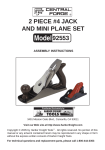
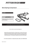
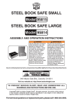
METAL PLANETARY
RING ROLLER
Model 36790
Assembly And Operation Instructions
Due to continuing improvements, actual product may differ slightly from the product described herein.
®
3491 Mission Oaks Blvd., Camarillo, CA 93011
Visit our website at: http://www.harborfreight.com
To prevent serious injury, read and understand
all warnings and instructions before use.
Copyright© 2000, 2006 by Harbor Freight Tools®. All rights reserved. No portion of this
manual or any artwork contained herein may be reproduced in any shape or form without
the express written consent of Harbor Freight Tools.
For technical questions or replacement parts, please call 1-800-444-3353.
THANK YOU for choosing a HARBOR FREIGHT TOOLS product. For future reference, please complete the
owner’s record below:
Model____________
Serial No.______________
Purchase Date______________
SAVE THE RECEIPT, WARRANTY AND THESE INSTRUCTIONS. It is important that you read the entire
manual to become familiar with the unit BEFORE you begin assembly.
Specifications
Construction
Rockwell Hardness
Ring Capacity
Flat Stock Capacity
Round Stock Capacity
Drive
Rollers
Handle
Weight
Warning:
5/16” Steel
26 RC
Unlimited
3/16” x 1”
1/4” Diameter
Gear
Heat Treated Steel
13-1/2” Long
13.25 lb.
The warnings, cautions and instructions discussed in this instruction manual cannot cover all
possible conditions and situations that may occur. It must be understood by the operator that
COMMON SENSE AND CAUTION ARE FACTORS WHICH CANNOT BE BUILT INTO THIS
PRODUCT, BUT MUST BE SUPPLIED BY THE OPERATOR.
The Operator
PLEASE REMEMBER:
Do not operate the product if under the influence of alcohol or drugs. Read warning labels on prescriptions to
determine if your judgment/reflexes might be impaired.
Do not wear loose clothing or jewelry as they can be caught in moving parts.
Protective gloves and non-skid footwear are recommended.
Wear restrictive hair covering to contain long hair.
Use eye and ear protection. Always wear ANSI approved impact safety goggles.
Maintain proper footing and balance at all times.
Use the right tool for the job. Do not attempt to force a small tool or attachment to do the work of a larger
industrial tool. There are certain applications for which this tool was designed. Do not modify this tool and do
not use this tool for a purpose for which it was not intended.
For your own safety, maintenance should be performed regularly by a qualified technician.
WARNING: The brass components of this product contain lead, a chemical known to the State of California to
cause birth defects (or other reproductive harm). (California Health & Safety code § 25249.5, et seq.)
REV 12/06
SKU 36790
For technical questions, please call 1-800-444-3353.
Page Work Area
TO AVOID RISK OF PERSONAL INJURY, EQUIPMENT DAMAGE, FIRE AND SHOCK, MAKE SURE YOUR
WORK AREA IS:
Free of damp, wet or rainy conditions.
Free of children (never let them handle tools or machinery).
Well-lit.
Clean and uncluttered.
Before Operating
Make sure all clamps, locks and bolts are tight, and that the Ring Roller is securely fastened to the
appropriate mounting surface.
Assembly
Your Ring Roller will require minor assembly prior to operation. It is important that you read the entire manual
to become familiar with the unit BEFORE you assemble and use the Ring Roller. Before assembling your
Ring Roller be sure that you have all parts described in the Parts List.
When assembling your Ring Roller, it will be helpful to refer to each of the operational Figures as well as to
the Parts List and Assembly Diagram on the last pages of this manual.
Assemble attachments based on the intended use of the Ring Roller only.
Mounting Surface: The mounting surface must be flat, level and capable of supporting the weight of the Roller
combined with the materials to be rolled. Mount the
Ring Roller on a solid mounting surface that is
capable of supporting the weight of the Ring
Roller and the leverage force of the Handle
movement.
Step 1)
Step 2)
Step 3)
Slide the Connector (#19) onto the
Drive Shaft II (#17) - see Figure 1.
Once the Connector (#19) is slid in
place on the Drive Shaft II (#17),
make certain that the holes in the
Connector (#19) line up with the
holes in the Drive Shaft II (#17).
Slide the Handle (#15) into the hole
in the Connector (#19) and Drive
Shaft II (#17)
- see Figure 1.
Secure the Connector (#19) to the
Drive Shaft II (#17) using the Taper
Pin (#20). Insert the Figure 1
Handle (#15)
Connector (#19)
Insert Taper Pin (#20) here
Base (#25)
Mounting Hole
SKU 36790
For technical questions, please call 1-800-444-3353.
Page Taper Pin (#20) into the hole as seen in Figure 1. If necessary, lightly tap the Taper Pin (#20)
into place.
Mounting
Step 1)
Set the Roller on your appropriate mounting surface as desired.
Warning:
The Metal Planetary Ring Roller must be securely mounted to an appropriate work surface
prior to use!
Step 2)
Make certain that you can operate the Handle (#15) comfortably.
Step 3)
Mark the appropriate mounting surface through the two holes located at the far ends of the
Base (#25).
Step 4)
Remove the Metal Planetary Ring Roller from the appropriate mounting surface. Drill holes
through the mounting surface at the marked locations.
Step 5)
Mount the unit using two bolts, lock washers, washers and nuts (in that order) sold separately.
Handle (#15)
Knob (#29)
Upper Drive Wheel (#4)
Lower Drive Wheel (#4)
Adjustable Wheel (#16)
Left Frame (#5)
Figure 2
SKU 36790
For technical questions, please call 1-800-444-3353.
Page Operation
When operating your Metal Planetary Ring Roller, it may be helpful to refer to each of the operational Figures
as well as to the Parts List and Assembly Diagram located on the last pages of this manual.
Never force the tool or attachment to do the work of a larger industrial tool. It is designed to do the job better
and more safely at the rate for which it was intended.
Step 1)
Determine the size ring you wish to obtain.
Warning:Do not use flat stock larger than 3/16” x 1”.
Do not use Round stock larger than 1/4”
Step 2)
Move the Adjustable Wheel (#16) up or down (as desired) by turning the Knob (#29)
- see Figure 2.
Step 3)
To obtain small size rings (approximately 1”), the Adjustable Wheel (#16) must be in its
uppermost position.
Step 4)
To obtain 2” rings, the Adjustable Wheel (#16) must be in the middle position.
Step 5)
To obtain larger rings, the Adjustable Wheel (#16) must be in its lowest position.
It is recommended that you practice on scrap stock to find the correct wheel adjustment to make the
desired size ring.
Step 6)
Insert the stock between the Upper Drive Wheel (#4) and between both the Adjustable Wheel
(#16) and lower Drive Wheel (#4) - see Figure 2.
Step 7)
Turn the Knob (#29) clockwise to clamp the stock between the Wheels.
Warning
After stock has been clamped between the Wheels, keep hands and fingers clear of the
Wheels while the handle is being rotated.
Step 8)
Rotate the Handle (#15) counterclockwise to process the ring.
Step 9)
To remove the completed rings, turn the Knob (#29) counterclockwise to loosen the clamping action.
PLEASE READ THE FOLLOWING CAREFULLY
The manufacturer and/or distributor has provided the parts list and assembly diagram in this manual as a reference tool only. Neither the manufacturer
or distributor makes any representation or warranty of any kind to the buyer
that he or she is qualified to make any repairs to the product, or that he or
she is qualified to replace any parts of the product. In fact, the manufacturer
and/or distributor expressly states that all repairs and parts replacements
should be undertaken by certified and licensed technicians, and not by the
buyer. The buyer assumes all risk and liability arising out of his or her repairs
to the original product or replacement parts thereto, or arising out of his
or her installation of replacement parts thereto.
If there is any question about a condition being safe or unsafe, do not operate the tool.
SKU 36790
For technical questions, please call 1-800-444-3353.
Page Maintenance
Cleaning:
Regularly clean the work surface using a non-toxic solvent.
Zerk Fittings (#1)
Figure 3
LUBRICATION:Your three lubrication points are the Drive Shaft I (#9), Drive Shaft II (#17) and the Adjustable
Shaft (#18). Grease using the Zerk Fittings (#1) - see Figure 3 above.
STORAGE:
Store in a dry area out of the reach of children.
Unpacking
When unpacking your Metal Planetary Ring Roller, check to make sure the following parts are included. If any
parts are missing or broken, please call HARBOR FREIGHT TOOLS at 1-800-444-3353.
Parts List
Part
Description
Q’ty
Part
Description
Q’ty
1
Zerk Fitting M8 x 1
3
15
Handle
1
2
# 10 C-Ring
5
16
Adjustable Wheel
1
2A
#22 C-Ring
1
17
Drive Shaft II
1
3
Hex Bolt M 10 x 60
1
18
Adjustable Shaft
1
4
Drive Wheel
2
19
Connector
1
5
Left Frame
1
20
Taper Pin 8 x 28
1
6
Copper Bushing
2
21
Hex Key Screw M10 x 60
2
7
Stand
1
22
Shaft (w/hole)
1
8
Bushing
1
23
Hex Key Screw M10 x 16
2
9
Drive Shaft I
1
24
Pin 3 x 12
1
10
Key 4 x 25
4
25
Base
1
11
Right Frame
1
26
Mounting Plate
1
12
Gear
2
27
Lead Screw
1
13
Cover
1
28
Locking Screw M6 x 6
1
14
Hex Key Screw M6 x 45
1
29
Knob
1
Note: Some parts are listed and shown for illustration purposes only and are not available
individually as replacement parts.
SKU 36790
For technical questions, please call 1-800-444-3353.
Page Assembly Diagram
SKU 36790
For technical questions, please call 1-800-444-3353.
Page