1
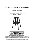
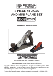
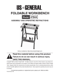
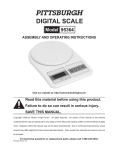
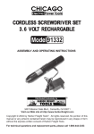
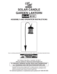
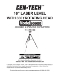
10 DRIP NOZZLE WATERING
DRIP KIT
Model 93261 / Model 46095
ASSEMBLY AND OPERATING INSTRUCTIONS
Due to continuing improvements, actual product may differ slightly from the product described herein.
3491 Mission Oaks Blvd., Camarillo, CA 93011
Visit our Web site at http://www.harborfreight.com
TO PREVENT SERIOUS INJURY, READ AND UNDERSTAND
ALL WARNINGS AND INSTRUCTIONS BEFORE USE.
Copyright© 2005 by Harbor Freight Tools®. All rights reserved. No portion of this
manual or any artwork contained herein may be reproduced in any shape or form
without the express written consent of Harbor Freight Tools.
For technical questions and replacement parts, please call 1-800-444-3353
REV 07/05
PRODUCT SPECIFICATIONS
Item
Hose Length/Diameter
Maximum
Operating Pressure
Accessories
Approximate Unit Weight
Description
Model 93261: 150 Ft., ¼” O.D. x 3/16” I.D.
Model 46095: 100 Ft., ¼” O.D. x 3/16” I.D.
55 PSI
Faucet to Hose Connector (Qty. 1) / Threaded Adapter Coupler (Qty. 1)
Water Pressure Regulator (Qty. 1) / Faucet Gasket (Qty. 1)
Faucet Gasket w/Filter Screen (Qty. 1) / Hose Tee (Qty. 14)
Plastic Tube (Qty. 5) / Tie-Down Stake (Qty. 15)
Plastic Hose Coupler (Qty. 2)
In-Line Hose Coupler w/Drip Nozzle Flow Thru w/Small Pin Hole (Qty. 10)
Hose Nail-Down Clip (Qty. 10) / Faucet Connector (Qty. 1)
Terminal Drip Nozzle w/No Pin Hole (Qty. 10)
3.20 Pounds
SAVE THIS MANUAL
You will need the manual for the safety warnings and precautions, assembly
instructions, operating and maintenance procedures, parts list and diagram.
Keep your invoice with this manual. Write the invoice number on the inside of
the front cover. Keep the manual and invoice in a safe and dry place for future
reference.
UNPACKING
When unpacking, check to make sure that all parts listed in the Parts List on
page 7 are included. If any parts are missing or broken, please call Harbor
Freight Tools at the number shown on the front cover of this manual as soon as
possible.
GENERAL SAFETY WARNINGS AND PRECAUTIONS
WARNING: When using tools to install this product, basic safety precautions
should always be followed to reduce the risk of personal injury and damage
to equipment.
Read all instructions before using this product!
1.
Keep work area clean. Cluttered areas invite injuries.
2.
Observe work area conditions. Do not use machines or power tools in
damp or wet locations. Don’t expose to rain. Keep work area well lighted.
SKU 93261
46095
For technical questions, please call 1-800-444-3353.
Page 2
Do not use electrically powered tools in the presence of flammable gases
or liquids.
3.
Keep children away. Children must never be allowed in the work area. Do
not let them handle machines, tools, or extension cords.
4.
Store idle equipment. When not in use, tools must be stored in a dry
location to inhibit rust. Always lock up tools and keep out of reach of children.
5.
Do not force the product. It will do the job better and more safely at the rate
for which it was intended. Do not use inappropriate attachments in an attempt
to exceed the product’s capacity.
6.
Use the right product for the job. Do not attempt to force a small product or
attachment to do the work of a larger industrial product. There are certain
applications for which this product was designed. Do not modify this product
and do not use this product for a purpose for which it was not intended.
7.
Dress properly. Do not wear loose clothing or jewelry as they can be caught
in moving parts. Protective, electrically non-conductive clothes and non-skid
footwear are recommended when working. Wear restrictive hair covering to
contain long hair.
8.
Use eye and ear protection. Always wear ANSI approved impact safety
goggles when setting up this product and when working with tools and
equipment.
9.
Do not overreach. Keep proper footing and balance at all times.
10. Maintain products with care. Inspect all components and the hose
periodically and, if damaged, have defective items repaired or replaced by an
authorized technician.
11. Disconnect when not in use. When the Drip Kit is not being used,
disconnect from the water source and store all components in a dry
location.
12. Stay alert. Watch what you are doing, use common sense. Do not
assemble or operate any product when you are tired.
13. Check for damaged parts. Before using any product, any part that
appears damaged should be carefully checked to determine that it will
operate properly and perform its intended function. Check for alignment and
binding of moving parts; any broken parts or mounting fixtures; and any
other condition that may affect proper operation. Any part that is damaged
should be properly repaired or replaced by a qualified technician. Do not
use the product if it is not working properly.
14. Replacement parts and accessories. When servicing, use only identical
replacement parts. Use of any other parts will void the warranty. Only use
SKU 93261
For technical questions, please call 1-800-444-3353.
Page 3
46095
accessories intended for use with this tool.
15. Do not operate this product if under the influence of alcohol or drugs.
Read warning labels on prescriptions to determine if your judgment or reflexes
are impaired while taking drugs. If there is any doubt, do not operate the
product.
16. Maintenance. For your safety, service and maintenance should be
performed regularly by a qualified technician.
Warning: The warnings, cautions, and instructions discussed in this instruction manual cannot cover all possible conditions and situations that may occur. It must be understood by the operator that common sense and caution
are factors which cannot be built into this product, but must be supplied by
the operator.
OPERATION
1.
Using the Faucet Connector (13), Faucet to Hose Connector (2), Threaded
Adapter Coupler (3), Water Pressure Regulator (4), Faucet Gaskets (5 and
6), and Hose (1 or 1A), assemble and secure these parts to the water
faucet, or water valve as illustrated. (See Figure A.)
FAUCET GASKET
(5)
FAUCET CONNECTOR
(13)
THREADED
ADAPTER COUPLER
(3)
WATER PRESSURE
REGULATOR
(4)
FAUCET GASKET
WITH FILTER SCREEN
(6)
FAUCET TO HOSE
CONNECTOR
(2)
HOSE
(1 OR 1A)
FAUCET GASKET
WITH FILTER SCREEN
(6)
WATER PRESSURE
REGULATOR
(4)
FAUCET TO HOSE
CONNECTOR
(2)
HOSE
(1 OR 1A)
FIGURE A
SKU 93261
46095
For technical questions, please call 1-800-444-3353.
Page 4
2.
Hand tighten all connections if possible. If pliers are used, care must be
taken not to overtighten components as they may break. (See Figure A.)
3.
Cut the end of the Hose (1 or 1A) at an angle. This will allow easier
insertion into the Faucet Hose Connector (2). Press and twist hose in 1/2
inch. (See Figure A.)
4.
Route the Hose along the desired watering locations. (See Figure B.)
5.
If necessary, use the Hose Nail-down Clips (12) to secure the Hose to a
wooden rail, pot, or other fixture. The Tie-down stakes can be used to
secure the Hose to dirt within the pot or on the ground.
6.
Decide on how the Drip Nozzles (11 & 14) will be connected.
7.
Pots over 8 inches in diameter may require 2 or more Drip Nozzles. In
planter boxes, place the Drip Nozzles every 12 inches. Main Hose runs
should not be over 50 feet in length. Hose connections to hanging plants
should not be over 10 feet in height.
8.
Use Scissors to cut the Hose at the desired location and length.
9.
The Hose Tees (7) can be used to tap off the main Hose line.
FIGURE B
10.
Turn on the water to flush out the Hose (1 or 1A) before taping off and
closing the end(s). This will blow out any debris within the Hose.
NOTE: Do not exceed the maximum 55 PSI water pressure for the
Hose.
11.
Use the Plastic Tubes (8) to close an open Hose (1 or 1A) end by
SKU 93261
For technical questions, please call 1-800-444-3353.
46095
Page 5
doubling over the Hose end and forcing it over the doubled Tube.
12.
Turn on the water and check each Drip Nozzle for dripping water. If the
flow is too slow, try removing the Water Pressure Regulator (4) and
retest the flow once again. If there are leaks in the Faucet Couplings,
hand tighten once again or remove and reassemble them using pipe
sealant tape (not included) on the threads.
MAINTENANCE
1.
Remove and clean out the Faucet Gasket with Filter Screen (6) every
month.
2.
Periodically remove Plastic Tubes (8) connected to Hose ends, and turn
on the water to blow out any debris.
3.
CAUTION! All maintenance, service, or repairs not mentioned in
this manual are only to be attempted by a qualified service technician.
PLEASE READ THE FOLLOWING CAREFULLY
THE MANUFACTURER AND/OR DISTRIBUTOR HAS PROVIDED THE PARTS DIAGRAM
IN THIS MANUAL AS A REFERENCE TOOL ONLY. NEITHER THE MANUFACTURER NOR
DISTRIBUTOR MAKES ANY REPRESENTATION OR WARRANTY OF ANY KIND TO THE
BUYER THAT HE OR SHE IS QUALIFIED TO MAKE ANY REPAIRS TO THE PRODUCT OR
THAT HE OR SHE IS QUALIFIED TO REPLACE ANY PARTS OF THE PRODUCT. IN FACT,
THE MANUFACTURER AND/OR DISTRIBUTOR EXPRESSLY STATES THAT ALL REPAIRS
AND PARTS REPLACEMENTS SHOULD BE UNDERTAKEN BY CERTIFIED AND
LICENSED TECHNICIANS AND NOT BY THE BUYER. THE BUYER ASSUMES ALL RISK
AND LIABILITY ARISING OUT OF HIS OR HER REPAIRS TO THE ORIGINAL PRODUCT
OR REPLACEMENT PARTS THERETO, OR ARISING OUT OF HIS OR HER INSTALLATION
OF REPLACEMENT PARTS THERETO.
SKU 93261
46095
For technical questions, please call 1-800-444-3353.
Page 6
PARTS LIST AND ASSEMBLY DIAGRAM
Part #
1
1A
2
3
4
5
6
7
8
9
10
11
12
13
14
Description
Hose, Neoprene, ¼” O.D. x 3/16” I.D. (Model 93261)
Hose, Neoprene, ¼” O.D. x 3/16” I.D. (Model 46095)
Faucet to Hose Connector
Threaded Adapter Coupler
Water Pressure Regulator
Faucet Gasket
Faucet Gasket with Filter Screen
Hose Tee
Plastic Tube
Tie-Down Stake
Plastic Hose Coupler
In-Line Hose Coupler with Drip Nozzle
Flow Thru (Has Small Pin Hole)
Hose Nail-Down Clip
Faucet Connector
Terminal Drip Nozzle (Has No Pin Hole)
Qty.
150 Ft.
100 Ft.
1
1
1
1
1
14
5
15
2
10
10
1
10
1
9
12
8
14
11
3
4
6
5
13
2
10
NOTE: Some parts are listed and shown for illustration
purposes only and are not available individually as replacement parts.
SKU 93261
46095
For technical questions, please call 1-800-444-3353.
7
Page 7