1
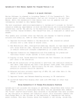
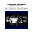
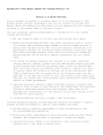
2-Stage Progressive Mini-Controller
&
2-Stage TPS and RPM Window Switch
INSTALLATION AND USER MANUAL
KWS002x rev G
i
Table of Contents
Page
1.
Overview ........................................................................................................................................................................................... 1
2.
Software Installation
Installation......................................................................................................................................................................... 1
3.
Software ............................................................................................................................................................................................ 2
3.1
Entering User Data....................................................................................................................................................................2
3.2
Throttle Position Sensor (TPS) ..................................................................................................................................................3
3.3
RPM ...........................................................................................................................................................................................3
3.4
Stage Set-up ...............................................................................................................................................................................3
3.4.1
Non-Progressive Mode Options .........................................................................................................................................4
3.4.2
Progressive Mode Options .................................................................................................................................................4
3.4.2.1 Time-Based Curve .........................................................................................................................................................4
3.4.2.2 RPM-Based Curve .........................................................................................................................................................4
3.5
4.
Upload / Download Configuration ............................................................................................................................................5
Installation
Installation......................................................................................................................................................................................... 5
4.1
Wide-Open-Throttle Setup .........................................................................................................................................................6
4.2
RPM Setup Verification .............................................................................................................................................................6
5.
Software and Firmware Updates
Updates..................................................................................................................................................... 6
6.
Disclaimer ......................................................................................................................................................................................... 7
7.
Warranty .......................................................................................................................................................................................... 7
8.
Wiring Diagram: 2-Stage Controller ............................................................................................................................................. 8
9.
Wiring Diagram: 2-Stage TPS and RPM Window Switch
Switch............................................................................................................ 9
10.
Wiring Diagram: 2-Stage TPS and RPM Window Switch (upgrade) ..................................................................................... 9
11.
Wiring Diagram: 2-Stage Progressive Mini-Controller ......................................................................................................... 10
KWS002x rev G
1
1.
Overview
The 2-STAGE TPS AND RPM WINDOW SWITCH is a digital controller that combines the functions
of a throttle position sensing switch and two RPM window switches all into a very compact module.
The device also supports low-voltage OEM, V10 or 3 cylinder TACH signals without the need for
additional adapters. It works with most OEM throttle position sensors including most drive-by-wire
vehicles. The manual trigger input allows the driver to over-ride the controller and disable or enable
the stages manually. By adding the optional FJO HIGH CURRENT SOLENOID DRIVER, it can be
upgraded to a 2-STAGE PROGRESSIVE MINI-CONTROLLER.
The 2-STAGE PROGRESSIVE MINI-CONTROLLER combines the functions of our 2-STAGE TPS
AND RPM WINDOW SWITCH and our HIGH CURRENT SOLENOID DRIVER all into one very
compact module. It can progressively drive two channels, each with a 40 amp load capacity
(continuous duty). The device also supports low-voltage OEM, V10 or 3 cylinder TACH signals
without the need for additional adapters. It works with most OEM throttle position sensors including
most drive-by-wire vehicles. This device also includes FJO's "real curve" ramp, which allows you to
create a progressive curve instead of just a ramp. The ramp can be either time based or RPM based.
All this and it’s only the size of a spark plug box.
2.
Software Installation
If you have the autorun feature enabled on your cdrom drive, wait for the navigation screen and follow
the instructions to install the software. If the application does not auto-start, go to the cdrom directory
and run “startpgm.exe”
Note: For Windows 98SE, the driver files will not be automatically installed. Once you have installed
the software and connect the controller, you will be prompted for the location of the driver files by the
windows “new hardware wizard”. The files are located in the “C:\Program Files\FJO Racing\2Stage
Mini-Controller\USBDriver” subdirectory.
KWS002x rev G
2
3.
Software
The following settings do not require that the controller be connected to the PC until you are ready to
UPLOAD. All changes made to the set-up require that you UPLOAD to the controller before installing
it in the vehicle. (See Upload/Download section).
3 .1
Entering User Data
Drag & Slide – data fields that have this feature have a down arrow button to the right. Clicking and
holding the button causes a slider bar to appear. Moving the mouse left or right while the slider is
displayed will decrease or increase the value.
Increment/Decrement buttons - data fields that have this
feature have up/down arrow buttons to the right. Click on either
of these to increase or decrease the value accordingly.
Menu pull-down – data fields that have this feature have a down arrow button to the right. Clicking
on the button will cause a pull-down menu to appear. To select, click on one of the displayed options.
Typing – clicking on the data field will highlight the value. You can then use the keyboard to enter the
value.
DO NOT connect the controller to your PC until you have installed the software.
KWS002x rev G
3
3 .2
Throttle Position Sensor (TPS)
Throttle Position Sensor (TPS) allows you to select if the output voltage from the throttle position
sensor increases (Rises) or decreases (Falls) at wide-open-throttle (WOT).
Note: If used with a WOT switch, set to “Rises” and connect the switch as shown in the wiring
diagram.
WARNING: setting this to the incorrect mode may result in nitrous and fuel being discharged while
the throttle plate is closed. Serious engine damage and possible injury can occur as a result.
3 .3
RPM
RPM Multiplier selects the correct pulse count for the RPM counter. Use the following as a guide to
determine the correct setting:
a)
Using a TACH signal - TACH signals will typically have 1 pulse per cylinder during 2
revolutions of the crankshaft (1 full cycle) and therefore the correct setting would be
÷(½ the number of cylinders)
Example: When using a TACH signal
4 cylinder setting would be ÷2
6 cylinder setting would be ÷3
8 cylinder setting would be ÷4
b)
Using a trigger signal from a coil - first determine how often it fires per revolution of the
crankshaft. The correct setting would be:
x1 for a waste-spark since it fires each revolution of the crankshaft
x2 for a full-sequential since it fires every other revolution.
This setting must be verified prior to operation. Verifying this setting will require the unit to be installed
on the vehicle – see installation instructions later in the manual.
3 .4
Stage Set-up
The following applies to both Stage 1 and Stage 2.
Present allows you to permanently turn off a stage. A check mark tells the controller to activate the
stage as per the configuration. No check mark means this stage is always OFF.
Progressive Solenoid Driver Connected sets the mode of the output stages. Blank means that the
output is configured to drive a relay. With a checkmark in this box, the controller is configured to drive
the FJO SOLENOID DRIVER in progressive mode. DO NOT use the progressive mode unless you
have the Progressive Mini-Controller or the optional FJO SOLENOID DRIVER module
connected to the Window switch controller.
Trigger Switch will setting determines if the trigger switch will enable, disable or have no effect on the
applicable stage when the switch is ON ( connected to 12 volts). The trigger switch input can be used
to control the output stages manually such as disabling them when the Transmission-brake is
engaged, or as a driver over-ride.
KWS002x rev G
4
Enable First-Gear Lockout allows you to disable a stage until the first time you pass through the RPM
window.
RPM Cutoff allows you to set the upper RPM threshold above which the nitrous will be turned off.
(useful with locked torque converters)
RPM Trigger allows you to set the minimum RPM required before the Nitrous can be triggered.
3.4.1 Non-Progressive Mode Options
During the RPM Window … determines if the relay attached to the stage output gets turned ON or
OFF when the stage is active.
3.4.2 Progressive Mode Options
FJO’s “Real Curve” technology allows you to drag and drop any dot on the ramp between 0-100%.
The controller will extrapolate between the dots thus creating a nitrous curve instead of the traditional
ramp. We have provided some additional tools to help smooth the overall curve, which we discuss in
the following sections.
Reset to Straight Line allows you to set the curve to a straight line between the Start and Final
targets. (to simulate a simple ramp)
Smooth When Dragging when checked will drag multiple dots along with the selected one. It will
attempt to soften rapid transitions from one step to the next in an effort to create a curve
Smooth Points will apply a smoothing algorithm to your curve. This button can be pressed multiple
times until the desired curve is achieved
Undo is an undo button. If you applied the smooth points feature or dragged a dot, this feature will
undo the change. It has multiple levels so you can undo several changes
Solenoid Frequency is the rate at which the controller cycles the solenoids. This number is
determined by the solenoid manufacturer.
Start sets the start percentage of the stage
3.4.2.1
Time-Based Curve
Final sets the final percentage of the stage. The ramp will maintain this level until the RPM cut-off is
reached or the stage is deactivated by the TPS or RPM window.
Delay sets the time that the controller will delay starting the ramp once a stage has been activated
RAMP sets the build time for the ramp
3.4.2.2
RPM-Based Curve
Final sets the percentage of the stage at the RPM End target.
RPM End sets the upper RPM limit of the curve. Above this RPM, the controller will maintain the final
percentage until the RPM Cut-off threshold is reached.
KWS002x rev G
5
3 .5
Upload / Download Configuration
DO NOT connect the controller to your PC until you have installed the software.
To connect the controller to your PC, use the USB cable supplied with the kit. The controller is
powered by the USB port on your computer and as such does not require any additional power
sources. Plug the USB cable into an available port on your PC.
Note: If you are using a USB hub, it must be capable of providing 100mA of current to power the
controller.
Once the software has identified the FJO 2-STAGE
SWITCH, the buttons will become fully visible and
the connected ICON will be green.
Clicking on the UPLOAD button will store your settings in the
controller. The “Config Uploaded” window will appear following a
successful upload.
You are now ready to install your 2-STAGE Controller on the vehicle.
4.
Installation
The 2-STAGE Controller is designed to be installed almost anywhere on the vehicle. Select a location
that is away from heat sources that can damage the wires. Before permanently installing the device,
we recommend that you complete the installation procedure below, as you will need access to the
potentiometer and have a clear view of the LEDs for the final steps. Using the wiring diagram
applicable to your application, connect the harness as illustrated.
Power Input should be connected to the arming switch and fused for 5 amps
Controller Ground should be connected to chassis ground as close as possible to the battery and
preferably not to the same location that the FJO HIGH CURRENT SOLENOID DRIVER is grounded
to.
Driver Ground (12 AWG black wire) from the SOLENOID DRIVER must be connected to a good
ground location that can handle 80 AMPS.
DO NOT connect to the ECU ground connection. While pulsing the solenoids, this will generate large
amounts of electrical noise that can interfere with the controller or your ECU.
TACH input is designed to work with most Tachometer signals (down to 3 Volts), without the need for
a separate adapter.
Trigger switch input requires a 12-volt signal to turn it on.
TPS signal input is designed to work with most throttle-position-sensors (TPS) and wide-openthrottle (WOT) switches.
KWS002x rev G
6
Stage 1 & 2 Control Outputs (Window Switch) are designed to trigger the FJO HIGH CURRENT
SOLENOID DRIVER or the ground side of a relay coil.
FJO HIGH CURRENT SOLENOID DRIVER is designed to handle a maximum load of 40 amps per
stage (continuous duty)
4 .1
1)
2)
3)
4)
5)
6)
7)
8)
4 .2
Wide-Open-Throttle Setup
Before connecting the 2-STAGE PROGRESSIVE SWITCH adjust the potentiometer to the
initial position by turning it 25 turns clockwise for a rising voltage TPS, or 25 turns
counterclockwise for a falling voltage TPS.
Disconnect the solenoids from the relays to prevent them from firing.
Turn on the ignition power and arm the 2-STAGE PROGRESSIVE SWITCH.
Verify that the RED / YELLOW / GREEN LEDs are off with the throttle in the idle position.
Push the throttle to the wide-open position (WOT) and hold it.
If the GREEN LED is on, adjust the potentiometer to turn it off by turning it clockwise for a
rising voltage TPS, or counterclockwise for a falling voltage TPS. Once the GREEN LED
goes out proceed to the next step.
Now turn the potentiometer the other way until it just comes back on and then one additional
turn.
Verify that the GREEN LED goes off at IDLE and on at WOT. Repeat steps 4-6 as
necessary.
RPM Setup Verification
1)
2)
3)
4)
5)
Disconnect the solenoids from the relays to prevent them from firing.
Turn on the ignition power and start the engine.
Arm the 2-STAGE PROGRESSIVE SWITCH.
Verify that the RED / YELLOW / GREEN LEDs are off with the throttle in the idle position.
Slowly increase the throttle until you reach the Turn On At RPM setting that you downloaded
for stage 1.
6) Watch the YELLOW LED. If you set the correct RPM multiplier it will come on just as you
reach the target RPM.
7) Now repeat steps 5 and 6 and watch the RED LED and use the Turn On At RPM setting that
you downloaded for stage 2.
8) If the LEDs come on at the right RPM, then you selected the correct multiplier.
9) If the LEDs come on too late then the RPM multiplier is too high and you need to set the
multiplier to ½ the previous setting and repeat the RPM set-up verification.
10) If the LEDs come on too soon then the RPM multiplier is too low and you need to set the
multiplier to 2x the previous setting and repeat the RPM set-up verification.
Note: DO NOT use the half-step multipliers unless this is a 3 or 10 cylinder application.
The installation is complete!
5.
Software and Firmware Updates
Free updates are available for the 2-Stage Controller and related software at www.fjoracing.com
KWS002x rev G
7
6.
Disclaimer
FJO Racing Electronics shall not be held responsible for any damages, howsoever caused, to any persons or
equipment during the installation or operation of its products. FJO Racing Electronics products are meant for
off-road use only, and make no claims as to the unit’s ability to meet local safety or emissions laws.
7.
Warranty
FJO Enterprises Inc. (FJO) warrants the material and workmanship of the equipment, components and parts
manufactured by FJO against defects under normal use and service. This warranty shall extend for 180 days
from the date of manufacture provided that the customer first returns the defective part or component through
an authorized distributor, shipping costs prepaid. Prior to returning a product for warranty inspection, the
customer must contact FJO’s service department with the product serial number to receive a WARRANTY
CLAIM NUMBER. Units returned without this number will be refused.
FJO may at its option, repair or replace without cost for parts and labour, the defective product. This warranty
does not cover finishes, normal wear and tear, nor does it cover damage resulting from accident, misuse, dirt,
tampering, unreasonable use, service attempted or performed by unauthorized service agencies, failure to
provide reasonable maintenance, or FJO products that have been modified or used for commercial reasons.
FJO specifically does not warrant equipment, parts or components purchased by FJO or the customer from
any third party manufacturers or suppliers. Rather, for any defect in respect of equipment, parts and
components purchased from third party manufacturers and suppliers, the customer shall have recourse only to
the terms of the warranty of that particular manufacturer or supplier. Any recommendations made by the third
party manufacturer or suppliers concerning the use or application of their products are those of the
manufacturer or supplier, and FJO extends no warranty with respect to the results obtained for their use. FJO
does not warranty those products in any way beyond the term of the warranty extended by the manufacturer or
supplier.
The warranty provided above, FJO’s obligations and liabilities hereafter, and the rights and remedies of the
customer are exclusive and in substitution for, and the customer waives all other warranties, guarantees,
obligations, liabilities, rights and remedies, expressed or implied, arising by law or otherwise, including (without
limitation) the implied warranties of merchantability or fitness of purpose, and any obligations or liability of FJO
arising from tort, or loss of use, revenue or profit, or for incidental or consequential damage.
KWS002x rev G
8
8.
Wiring Diagram: 2-Stage Controller
5A Fuse
White
A
White/R ed
B
C
D
Power (+12V)
Throttle posit ion sensor
Red
Trigger Switch Input
Green
R PM
E
F
G
Yello w
H
Stage 1 con trol outp ut
Stage 2 con trol outp ut
Oran ge
J
Black
K
Ground
2-STAGE TPS and RPM WINDOW SWITCH
A
B
C
D
5A Fu se
White
White/Red
Power (+12V)
Throt tle position sensor
Red
Trigger Switch Input
G reen
RPM
E
F
G
H
J
K
Bla ck
Ground
Stage 1 So lenoid grou nd
Stage 2 So lenoid grou nd
2-STAGE Progressive Mini-Controller
KWS002x rev G
9
9.
Wiring Diagram: 2-Stage TPS and RPM Window Switch
Arming SW
j
Power (+12V)
5A Fuse
to Throttle-position Sensor
Wide-open Throttle SW
B
C
D
j
White
Trigger Switch
W hite /Red
j
A
Re d
Green
j
F
G
J
K
Yellow
Orange
Black
Nitrous Oxide
` `
H
to TACH signal
Stage 1 Relay
E
Fuel
j
Gr ound
Nitrous Oxid e
Stage 2 Relay
Required if no
throttle position
sensor is present
Fuel
Not used when
Wide-open throttle
switch is used
to battery
10. Wiring Diagram: 2-Stage TPS and RPM Window Switch (upgrade)
A rming SW
j
5A Fuse
Power (+12V)
to battery
to Throttle-position Sens or
Wide-ope n Throt tle SW
j
White
Trigge r Swi tc h
W hite/Red
j
Red
Green
t o TA CH signal
Black
Ground
Fuel Sole no id
Stage 2
Nitro us Solenoid
Required if no
throttle position
sensor is present
F uel Sol eno id
Nitr ous So leno id
Not used when
Wide-open throttle
switch is used
KWS002x rev G
Stage 1
j
j
` `
Yellow
O range
10
11.
Wiring Diagram: 2-Stage Progressive Mini-Controller
A rmi ng SW
j
5A Fuse
Power (+12V)
to battery
to Throttle-position Sens or
Wide-ope n Throt tle S W
j
White
Trigger Swi tc h
W hite/Red
j
Red
Green
t o TA CH signal
Ground
Fuel Sole no id
Ground
Stage 1
Nitro us Solenoid
Required if no
throttle position
sensor is present
F uel Sol eno id
Nitr ous So leno id
Not used when
Wide-open throttle
switch is used
KWS002x rev G
Stage 2
j
` `
j
Black