1
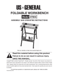
PORTABLE THREADING
MACHINE
41876
ASSEMBLY & OPERATING INSTRUCTIONS
Due to continuing improvements, actual product may differ slightly from the product described herein.
®
3491 Mission Oaks Blvd., Camarillo, CA 93011
Visit our Web site at http://www.harborfreight.com
TO PREVENT SERIOUS INJURY,
READ AND UNDERSTAND ALL WARNINGS
AND INSTRUCTIONS BEFORE USE.
Copyright©1999 by Harbor Freight Tools® . All rights reserved. No portion of this manual or any
artwork contained herein may be reproduced in any shape or form without the express written
consent of Harbor Freight Tools.
For technical questions and replacement parts, please call 1-800-444-3353.
THANK YOU for choosing a HARBOR FREIGHT TOOLS product. For future reference, please complete the
owner’s record below:
Model____________
Serial No._____________
Purchase Date_______________
SAVE THE RECEIPT, WARRANTY AND THESE INSTRUCTIONS. It is important that you read the entire
manual to become familiar with the unit BEFORE you begin assembly.
Technical Specifications
Electrical Requirements:
Die Sizes:
Plug, Cord and Switch:
Overall Dimensions:
Weight:
Accessories Included:
Warning:
110V, 12 Amp, 60 Hz
1/2", 3/4", 1", 1-1/4"
UL Listed
24" x 7-1/2" x 3-1/4"
12.5 Lbs.
Oil Can, Side Handle, Cast Iron Clamp, Blow Mold Carrying Case
The warnings, cautions and instructions discussed in this instruction manual
cannot cover all possible conditions and situations that may occur. It must
be understood by the operator that COMMON SENSE AND CAUTION ARE
FACTORS WHICH CANNOT BE BUILT INTO THIS PRODUCT, BUT
MUST BE SUPPLIED BY THE OPERATOR.
The Operator
PLEASE REMEMBER:
Do not operate the product if under the influence of alcohol or drugs. Read warning labels on prescriptions to
determine if your judgment/reflexes might be impaired.
Do not wear loose clothing or jewelry as they can be caught in moving parts.
Protective gloves and non-skid footwear are recommended.
Wear restrictive hair covering to contain long hair.
Use eye and ear protection. Always wear ANSI approved impact safety goggles.
Maintain proper footing and balance at all times.
Do not abuse the power cord. Do not yank on cord to disconnect it from outlet. Keep the cord away from heat,
oil and sharp edges.
Avoid unintentional starting. Do not carry any tool with your finger on the trigger.
REV 12/05
SKU 41876
For technical questions, please call 1-800-444-3353.
Page 2
Work Area
TO AVOID RISK OF PERSONAL INJURY, EQUIPMENT DAMAGE, FIRE AND SHOCK, MAKE SURE YOUR
WORK AREA IS:
Free of damp, wet or rainy conditions.
Free of flammable gasses or liquids.
Free of children (never let them handle tools or machinery).
Well-lit.
Clean and uncluttered.
Well-ventilated.
Before Operating
Before operating your Portable Threading Machine check for damaged parts.
DO NOT exceed the maximum capacity of the tool.
Never force the tool or attachment to do the work of a larger industrial tool. It is designed to do the job better
and more safely at the rate for which it was intended.
Do not try to use inappropriate attachments in an attempt to exceed the tool’s capacity. Approved accessories
are available from Harbor Freight Tools.
Check for damaged parts. Before using any tool, any part that appears damaged should be carefully checked
to determine that it will operate properly and perform its intended function.
Make sure all clamps, locks and bolts are tight.
Make certain to turn off and unplug the Portable Threading Machine when loading or when doing any
maintenance. The tool should always be turned off and unplugged when not in use.
Do not reach over or across running machines.
Note: Performance of this tool may vary depending on variations in local line voltage. Extension cord usage
may also affect tool performance.
SKU 41876
For technical questions, please call 1-800-444-3353.
Page 3
Grounding/Voltage Warning
Common household current is 110-120 volts. As long as the outlet used with the tool is rated from 110-120V
there will be no complications using it with household receptacles. Plug the tool into a 110-120v properly
grounded outlet protected by a 15-amp, dual element time delay or circuit breaker.
NEVER try to plug a 110-120V tool into a 220-240V circuit or serious complications and possible injury to the
operator may occur. The plugs have different shapes to prevent this.
Extension Cords
Your tool has a three-prong plug, therefore you must use a three-prong extension cord. Only use rounded jacket
extension cords listed by the Underwriters Laboratories (UL). Improper use of extension cords may cause
inefficient operation of your tool which can result in overheating. Be sure your extension cord is rated to allow
sufficient current flow to the motor.
If you are using the tool outdoors, use an extension cord rated for outdoor use (signified by “WA” on the jacket).
The extension cord must have a minimum wire size depending on the amperage of the tool and the length of the
extension cord. This size is determined by its AWG (American Wire Gauge) rating. The smaller the gauge, the
greater the cable’s capacity. The amount of cords used does not matter: Total length determines the minimum
AWG rating. Every cord must meet the AWG rating. Use the chart below to determine what AWG rating is required
for your situation. Cord length is rated in feet. Harbor Freight Tools can supply UL listed and outdoor rated
cords in multiple AWG ratings if needed.
AWG RATING CHART
CORD LENGTH 25’
50’
75’
100’
125’
150’
175’
200’
AMPS
AWG
AWG
AWG
AWG
AWG
AWG
AWG
AWG
18
16
14
14
18
16
14
12
16
14
12
12
16
14
12
12
14
14
12
12
14
12
12
12
12
12
12
—-
12
12
——-
0-10.0
10.1-13.0
13.1-15
15-18
DO NOT MODIFY YOUR PLUG IN ANY WAY. IF YOU HAVE ANY DOUBT, CALL A QUALIFIED ELECTRICIAN.
SKU 41876
For technical questions, please call 1-800-444-3353.
Page 4
Preparation for Pipe Threading
Your Portable Threading Machine comes fully assembled but will require insertion of the Die prior to operation.
It is important that your read the entire manual to become familiar with the unit BEFORE you use it. Be sure
that you have all parts described in the Parts List. To help you with assembly, please refer to the assembly
diagram on page 7 and the parts list on page 6.
Step 1)
Determine the size of the pipe to be threaded.
Step 2)
Select the appropriate die to be used. Four different Dies are included with the Threading Machine.
The Dies are the following sizes: 1/2", 3/4", 1", and 1-1/4". The dies are intended for use on
standard schedule 40 and schedule 80 steel pipe.
Step 3)
Insert the die into the Worm Gear (7) of the Machine. The dies will fits into the Worm Gear either
from the left or the right side of the tool. Make sure that the die is held in place by the Retaining
Ring (8) before proceeding. The Machine is pressure fitted so once the die is inserted properly, it
may require light tapping with a wooden mallet to remove the die.
Step 4)
Verify that the oil can is filled with oil and ready to be used during the threading operation.
Step 5)
The Pipe Clamp (29) should always be used to secure and support the pipe during the threading
operation. The round Clamp extension should parallel the pipe.
Step 6)
Located in front of the ON/OFF trigger switch is a Forward/Reverse switch which determines the
direction of the threading operation. With the Machine held in the right hand:
Switch in right position = Clockwise rotation
Switch in left position = Counterclockwise rotation
Operation
Now that the proper die is installed, you are ready to insert the pipe, secure it, and begin cutting threads.
Step 1)
Insert pipe into the rear of the die - see illustration to
the right. Verify that the inside diameter of the die
matches the outside diameter of the pipe.
Step 2)
Make sure that the Clamp (29) is effectively clamping
the pipe and that the pipe is well supported while
threads are being cut. During threading, use the round
Clamp extension for torque on the pipe.
Caution:
Make sure that pipe end and threads of the die are
sufficiently oiled at all times. Otherwise the die life
will be shortened and the threads will be rough.
Step 3)
Set the Switch to the right (Forward) position. While
holding the grip with one hand, press the trigger in
and pull up on it to turn the machine on. Apply
pressure to the pipe until the die engages the pipe
cutting two to three threads.
Step 4)
From this point, the die will automatically be drawn over the pipe and a standard taper thread will
be cut.
Step 5)
When the proper amount of threads are cut, release the trigger switch to stop the Machine. Move
the Forward/Reverse switch to the left position (Reverse) pulling in and up on the trigger to turn
the machine on. This will disengage the die from the pipe.
Step 6)
When sliding the pipe out of the machine, be careful not to damage the newly cut threads.
REV 12/05, 01/07
SKU 41876
For technical questions, please call 1-800-444-3353.
Page 5
Maintenance
Step 1)
Clean the Portable Threading machine after each use. Clean dies after each use. Check for
broken teeth or pipe material between teeth.
Motor Brushes
Step 1)
Using a small standard screwdriver, remove the Brush Cap. When you remove the Brush Cap, the
Brush may spring out. Do not lose the Brush. If the brush does not spring out, gently remove it
using the tip of your screwdriver.
Step 2)
Examine the Brush surface. If the Brush is worn more than 1/4" replace the brush. The surface
should be smooth and clean. If scratch marks appear, or if the brush is broken, replace the brush
immediately with an approved replacement brush from Harbor Freight Tools.
Step 3)
Screw the Brush Cap back into the Brush Holder and tighten.
Store your Threading Machine in the Carrying Case provided. Make certain it is stored out of the reach of children.
Unpacking
When unpacking your Portable Threading Machine, check to make sure the following parts are included. If any
parts are missing or broken, please call HARBOR FREIGHT TOOLS at 1-800-444-3353.
Parts List
Part
Description
Q'ty Part
Description
Q'ty Part
Description
Q'ty
1
Motor
1
7
Worm Gear
1
19 Spacer
1
2
Worm Gear Cover
1
8
Retaining Ring
1
20 Gear
1
3
Screw
4
9
Ring
1
21 Spacer
1
4A 1/2" Die Plate
1
10 Spacer
1
22 Spacer
1
4B 3/4" Die Plate
1
11 Ring
1
23 M5 x 12 Hex Screw
2
4C 1" Die Plate
1
12 Spacer
1
24 Handle Cover
1
4D 1-1/4" Die Plate
1
13 Snap Ring
1
25 Spacer
1
5A * 1/2 “ Cutter Head
1
14 Bearing
1
26 Screw
1
5B * 3/4" Cutter Head
1
15 Bolt
1
27 Ring
1
5C * 1" Cutter Head
1
16 Straight Key 4x15
1
28 Handle
1
5D * 1-1/4" Cutter Head
1
17 Bearing
1
29 Clamp
1
1
18 Bearing
1
6
Ring
* Cutter Head includes cutter blades
PLEASE READ THE FOLLOWING CAREFULLY
THE MANUFACTURER AND/OR DISTRIBUTOR HAS PROVIDED THE PARTS DIAGRAM IN THIS
MANUAL AS A REFERENCE TOOL ONLY. NEITHER THE MANUFACTURER NOR DISTRIBUTOR MAKES
ANY REPRESENTATION OR WARRANTY OF ANY KIND TO THE BUYER THAT HE OR SHE IS QUALIFIED
TO MAKE ANY REPAIRS TO THE PRODUCT OR THAT HE OR SHE IS QUALIFIED TO REPLACE ANY
PARTS OF THE PRODUCT. IN FACT, THE MANUFACTURER AND/OR DISTRIBUTOR EXPRESSLY STATES
THAT ALL REPAIRS AND PARTS REPLACEMENTS SHOULD BE UNDERTAKEN BY CERTIFIED AND LICENSED TECHNICIANS AND NOT BY THE BUYER. THE BUYER ASSUMES ALL RISK AND LIABILITY
ARISING OUT OF HIS OR HER REPAIRS TO THE ORIGINAL PRODUCT OR REPLACEMENT PARTS
THERETO, OR ARISING OUT OF HIS OR HER INSTALLATION OF REPLACEMENT PARTS THERETO.
REV 09/02; 12/05
SKU 41876
For technical questions, please call 1-800-444-3353.
Page 6
Assembly Diagram
Wiring Diagram
SKU 41876
For technical questions, please call 1-800-444-3353.
Page 7