1
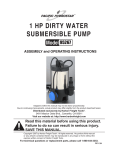
SHALLOW WELL PUMP
1 HP - Stainless Steel
Model 47906
ASSEMBLY and OPERATING
INSTRUCTIONS
®
3491 Mission Oaks Blvd., Camarillo, CA 93011
Visit our Web site at http://www.harborfreight.com
Copyright © 2002 by Harbor Freight Tools®. All rights reserved. No portion of this
manual or any artwork contained herein may be reproduced in any shape or form
without the express written consent of Harbor Freight Tools .
For technical questions and replacement parts, please call 1-800-444-3353
Specifications
Motor
Discharge Size
Maximum Flow
Maximum Suction Depth
Maximum Lift
Overall Dimensions
Pressure Tank Capacity
Maximum Pressure
Tank Hose Length
Weight
120 Volt, 60 Hz, 5 Amps (start-up)
Single Phase, 3400 RPM
1” Diameter
898 GPH
26 Feet
164 Feet
19” H x 10-5/8” W x 17-1/2” Long
5 Gallons
72 PSI
10 Inch
29-3/4 Lbs.
Save This Manual
You will need the manual for the safety warnings and precautions, assembly instructions,
operating and maintenance procedures, parts list and diagram. Keep your invoice with this
manual. Write the invoice number on the inside of the front cover. Keep the manual and
invoice in a safe and dry place for future reference.
Safety Warnings and Precautions
WARNING: When using tool, basic safety precautions should always be followed to
reduce the risk of personal injury and damage to equipment.
Read all instructions before using this tool!
1.
Keep work area clean. Cluttered areas invite injuries.
2.
Observe work area conditions. Do not expose this pump to rain or direct immersion.
Don’t expose to rain. Keep work area well lighted. Do not use electrically powered tools
in the presence of flammable gases or liquids.
3.
Keep children away. Children must never be allowed in the work area. Do not let them
handle Pump.
4.
Use the right pump for the job. Do not attempt to force a small Pump to do the work of
a larger industrial Pump. There are certain applications for which this Pump was
designed. It will do the job better and more safely at the rate for which it was intended.
Do not modify this Pump and do not use this Pump for a purpose for which it was not
intended.
5.
Dress properly. Do not wear loose clothing or jewelry as they can be caught in moving
parts. Protective, electrically nonconductive clothes and nonskid footwear are
recommended when working. Wear restrictive hair covering to contain long hair.
6.
Use eye and ear protection. Always wear ANSI approved impact safety goggles and
ear protection.
7.
Do not overreach. Keep proper footing and balance at all times. Do not reach over or
across running machines.
8.
Maintain Pump with care. Keep Pump clean for better and safer performance. Inspect
tool cords periodically; If damaged, have them repaired by a qualified technician.
SKU 47906
For technical questions, please call 1-800-444-3353.
Page 2
9.
Disconnect power. Unplug Pump when not in use.
10. Stay alert. Watch what you are doing, use common sense. Do not install Pump when
you are tired.
11. Check for damaged parts. Before using Pump, any part that appears damaged
should be carefully checked to determine that it will operate properly and perform its
intended function. Check for alignment and binding of moving parts; any broken parts
or mounting fixtures; and any other condition that may affect proper operation. Any part
that is damaged should be properly repaired or replaced by a qualified technician.
12. Guard against electric shock. Prevent body contact with grounded surfaces such as
pipes, radiators, ranges, and refrigerator enclosures.
13. Replacement parts and accessories. When servicing, use only identical
replacement parts. Use of any other parts will void the warranty. Only use accessories
intended for use with this tool. Approved accessories are available from Harbor Freight
Tools.
14. Do not install Pump if under the influence of alcohol or drugs. Read warning
labels on prescriptions to determine if your judgment or reflexes are impaired while
taking drugs. If there is any doubt, do not install the Pump.
15. Use proper size and type extension cord. If an extension cord is required, it must be
of the proper size and type to supply the correct current to the tool without heating up.
Otherwise, the extension cord could melt and catch fire, or cause electrical damage to
the tool. This tool requires use of an extension cord of 0 to 10 amps capability (up to
50 feet), with wire size rated at 18 AWG. Longer extension cords require larger size
wire. If you are using the tool outdoors, use an extension cord rated for outdoor use
(signified by “WA” on the jacket).
16. Maintenance. For your safety, maintenance should be performed regularly by a
qualified technician.
Warning: People with pacemakers should consult with their physician(s) before
using this product; operation of equipment in close proximity to a heart pacemaker
could cause interference or failure of the pacemaker.
Warning! Never operate this pump if the power cord or electrical components are
damaged or the seals are compromised. Never plug in the power cord when wet or
standing on damp or wet ground. Exercise extreme caution when working with electrical
equipment in the presence of water to maintain your personal insulation to avoid shock.
Do not allow others in the work area when working with electrical equipment. Use GFCI
outlets when using this pump.
Note: Performance of this tool (if powered by line voltage) may vary depending on variations
in local line voltage. Extension cord usage may also affect tool performance.
Warning: The warnings, cautions, and instructions discussed in this instruction manual
cannot cover all possible conditions and situations that may occur. It must be understood
by the operator that common sense and caution are factors which cannot be built into
this product, but must be supplied by the operator.
SKU 47906
For technical questions, please call 1-800-444-3353.
Page 3
Unpacking
When unpacking, check to make sure the parts listed on pages 7 and 8 are included. If any
parts are missing or broken, please call Harbor Freight Tools at the number on the cover of
this manual as soon as possible.
Installation
Note: For intake and discharge hose locations, see FIGURE 1 on page 5.
Note: If power cords must be extended, only use UL approved power cords that are 18 Gauge
wire. Do not extend the power cords more than 50 feet.
1. Install the pump on a rigid, level platform above the water level. This platform must provide
a solid, level surface that is capable
of supporting the weight of the pump,
and attached piping filled with water.
Never allow the pump to become
Typical Installation
immersed in water.
2. The level of the intake port should not
be more than 12-15 feet above the
water. Pumping efficiency falls off as
the height above the water level
Discharge
increases.
Intake
Pump
3. Keep the vertical lift that the pump
must move water before discharge, to
a minimum. Vertical delivery above a
few feet will degrade pump efficiency.
4. The intake port must have a screen (not included) attached to prevent introduction of
debris into the pump. At the end of the discharge pipe, either purchase a pre-made screen
to fit, or wrap loose screen and secure with wire.
Note: A foot valve (not included), installed on the suction inlet, is recommended to insure that
the pump will keep it prime.
5. Lay out the intake and discharge pipes with as few turns as possible to prevent air pockets
within the lines. Air pockets interfere with pressure switch performance.
6. Intake and discharge pipes must have a minimum of 1” to 1-1/4” diameter. Systems with
larger vertical components should have larger diameter piping. Keep in mind that the
maximum vertical lift (total vertical distance from the inlet screen to the discharge outlet)
is 140 feet.
7. For your protection, the power outlet used should have a Ground Fault Circuit Interrupter
(GFCI). Have it installed by a qualified electrician. Keep the power line safely away from
water.
8. The inlet and discharge lines should not be wedged or stressed in a way that puts strain
on the pump. Do not support the pump with the inlet and discharge lines.
9. This is a self starting pump that uses a pressure switch. Once the power cord is connected,
the pump can start at any time. Do not handle or perform maintenance on the pump
if the power cord is plugged in.
REV 12/05
SKU 47906
For technical questions, please call 1-800-444-3353.
Page 4
Discharge
FIGURE 1
Priming Valve Inlet
Intake
Pressure
Meter
Air Valve
(not visible)
Note: Compression Tank (#1A) has a rubber bladder inside. This bladder must be pumped up with between 21 and
29 PSI of air at all times. On the end of the Compression Tank opposite the side with the Pressure Meter, is an air
valve located under a cover. Remove the cover over the air valve and periodically monitor this air valve with an air
pressure gauge to insure that the rubber bladder maintains the required 21 to 29 PSI.
Operation
Warning! Never pump liquids containing abrasive materials such as sand. Never pump
flammable, corrosive, or volatile liquids.
Warning! Never plug in the power cord when wet or standing on damp or wet ground. Do not
plug in the power cord until step number 4 below.
1. Make sure the intake pipe is fully submerged before operating the pump.
2. Gently insert a screwdriver into the motor shaft and make sure the shaft turns freely.
(See Figure 1)
3. Important Note: Before starting the pump for the first time, prime it by pouring
clean water into the Priming Valve Inlet (see Figure 1). If water leaks from the drain
valve underneath the pump, securely close it and refill the unit.
NOTE: It is necessary that you install a foot valve (not included), if you are drawing
water from a source that is lower than the pump. The foot valve should be installed on
the bottom of the inlet pipe. A foot valve is a one way valve that will only allow the water
to flow in one direction. This should prevent the need to prime the pump every time
you use it by keeping the water in the inlet pipe from draining out after the pump is
turned off. Check the pump for prime each time you use it. Running the pump dry will
damage it.
4.
To begin pumping, plug in the power cord.
SKU 47906
REV 11/05, 09/06
For technical questions, please call 1-800-444-3353.
Page 5
Troubleshooting
Problem
The pump won’t start
Cause
No power
Blocked Impeller
Pressure switch disconnected
Thermal Protection cut out
Solution
Check connections
Free the motor shaft
Check gauge
Allow pump to cool
The pump operates but it
won’t discharge water
Inlet tube not submerged
Air in suction pipe
Inlet screen clogged
Lifting height exceeded
Submerge the inlet
Check pipe and seals
Clean screen
Reduce lifting height
Pump has low capacity
Inlet pipe is too small
Liquid is too dirty
Lifting height exceeded
Tank’s rubber bladder underinflated.
Increase pipe diameter
Clean screen frequently
Reduce lifting height
Inflate to 21- 29 PSI
Never disassemble the pump or motor as this will damage the water seals. All repairs
should be performed by a qualified technician.
Maintenance
Always disconnect pump from power source before attempting any maintenance.
1. Clean the inlet screen regularly to remove accumulated debris.
2. Use air pressure gauge to test air pressure in Tank’s rubber bladder. Air pressure should
range between 21and 29 PSI.
3. Wipe the pump clean with a soft, damp cloth with soapy water. Do not use solvents. Do
not get the electrical components wet.
4.
5.
If storing the pump for a long time, store it in a dry location, and apply a light layer of oil to
the metal parts prior to storage, to inhibit rust.
To drain the pump, disconnect the water lines and turn it upside down.
PLEASE READ THE FOLLOWING CAREFULLY
THE MANUFACTURER AND/OR DISTRIBUTOR HAS PROVIDED THE PARTS DIAGRAM IN THIS
MANUAL AS A REFERENCE TOOL ONLY. NEITHER THE MANUFACTURER NOR DISTRIBUTOR MAKES
ANY REPRESENTATION OR WARRANTY OF ANY KIND TO THE BUYER THAT HE OR SHE IS QUALIFIED
TO MAKE ANY REPAIRS TO THE PRODUCT OR THAT HE OR SHE IS QUALIFIED TO REPLACE ANY
PARTS OF THE PRODUCT. IN FACT, THE MANUFACTURER AND/OR DISTRIBUTOR EXPRESSLY STATES
THAT ALL REPAIRS AND PARTS REPLACEMENTS SHOULD BE UNDERTAKEN BY CERTIFIED AND
LICENSED TECHNICIANS AND NOT BY THE BUYER. THE BUYER ASSUMES ALL RISK AND LIABILITY
ARISING OUT OF HIS OR HER REPAIRS TO THE ORIGINAL PRODUCT OR REPLACEMENT PARTS
THERETO, OR ARISING OUT OF HIS OR HER INSTALLATION OF REPLACEMENT PARTS THERETO.
SKU 47906
For technical questions, please call 1-800-444-3353.
REV 09/06
Page 6
Parts List
Part
1
Description
Screw M8x12
Qty.
Part
4
24
Description
Waterproof Switch
Qty.
1
2
Motor Housing
1
25
Screw 3.5 x 20
3
3
Fan Blade
1
26
Hex Nut M8x20
4
4
Rear Cover
1
27
Front Cover
1
5
Spring Washer
1
28
Rubber Ring
1
6
Motor Bolt M5x125
4
29
0-ring
1
7
Stator
1
30
Flange
1
8
Bearing
1
31
Immobile Ring
1
9
Rotor
1
32
Motor Ring
1
10
Bearing
1
33
Impeller
1
11
Rubber Sheath
1
34
Flow Guide Plate
1
12
Screw 4.2x15
2
35
0-ring
1
13
Cable Block
1
36
Flow Guide Assy.
1
14
Cable Sleeve
1
37
0-ring
1
15
Connection Cable
1
38
Pump Shell
1
16
Screw 2.9x15
4
39
Lg. Valve Cover
2
17
Waterproof Cover
1
40
Large Bushing
1
18
Rubber Cover
1
41
Sealed Latex
1
19
0-ring
1
42
Screw M8x20
4
20
Capacitor Cover
1
43
0-ring
1
21
Capacitor
1
44
Small Bushing
1
22
Side Cover
1
45
Small Valve Cover
1
23
Switch Seal Plate
1
Assembly Drawing
SKU 47906
For technical questions, please call 1-800-444-3353.
Page 7
Assembly Drawing A
Note: When ordering a part from this drawing, you must include the suffix “A”
with the number.
REV 08/05
SKU 47906
For technical questions, please call 1-800-444-3353.
Page 8