1
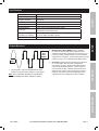
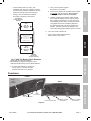
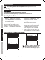
Table of Contents
Safety
Safety.......................................................... 2
Specifications.............................................. 5
Setup........................................................... 6
Operation..................................................... 8
Maintenance................................................ 9
Parts List and Diagram............................... 11
Warranty..................................................... 12
WARNING SYMBOLS AND DEFINITIONS
This is the safety alert symbol. It is used to alert you to potential personal injury hazards.
Obey all safety messages that follow this symbol to avoid possible injury or death.
Setup
Indicates a hazardous situation which, if not avoided,
will result in death or serious injury.
Indicates a hazardous situation which, if not avoided,
could result in death or serious injury.
Indicates a hazardous situation which, if not avoided,
could result in minor or moderate injury.
Addresses practices not related to personal injury.
Operation
Important Safety Information
Read all safety warnings and instructions.
Failure to follow the warnings and instructions may result in electric shock, fire and/or serious injury.
Save all warnings and instructions for future reference.
General Precautions
Maintenance
1. People with pacemakers should consult their
physician(s) before use. Electromagnetic fields in
close proximity to heart pacemaker could cause
pacemaker interference or pacemaker failure.
2. WARNING: The brass components of this
product contain lead, a chemical known to
the State of California to cause birth defects
(or other reproductive harm). (California
Health & Safety code § 25249.5, et seq.)
3. WARNING: This product contains or, when
used, produces a chemical known to the
State of California to cause cancer and birth
defects or other reproductive harm. (California
Health & Safety Code § 25249.5, et seq.)
4. The warnings, precautions, and instructions
discussed in this instruction manual cannot
cover all possible conditions and situations
that may occur. It must be understood by the
operator that common sense and caution are
factors which cannot be built into this product,
but must be supplied by the operator.
Installation Precautions
Page 2
For technical questions, please call 1-800-444-3353.
Item 69662
3. Keep combustible materials and gasses away
from the inverter. The inverter produces sparks
and heat during operation and can start a fire.
4. Connect to 12 VDC power supply only. A power
supply with lower voltage will not operate the Inverter
correctly, and higher voltage could damage the unit.
5. Connect input polarity properly. Incorrect connection
will damage inverter and void warranty.
6. Do not use in a marine application.
This inverter is not intended to withstand the highly
corrosive conditions in marine applications and
would quickly be rendered inoperable or unsafe.
8. Use cables that are thick enough. The more power
(amps) or the longer the cables, the thicker they
need to be to prevent overheating and fire.
9. Install as close to DC source as possible, but not
in a closed area with vented lead-acid batteries.
Vented lead-acid batteries release explosive
hydrogen gas that can be ignited by the inverter.
Safety
2. To allow proper cooling, install in indoor wellventilated area and do not cover ventilation openings
or cooling fins. Do not install in engine compartment.
Especially avoid placing the Inverter on carpets
and rugs; they are not only flammable, but
they also obstruct vents underneath it.
7. Keep inverter dry and clean. Do not expose
to rain, snow, spray, bilge water or dust.
10. Mount inverter horizontally.
11. Verify that installation surface has no hidden
utility lines before drilling or driving screws.
12. This product is not a toy. Keep it away from children.
13. Do not use with positive ground electrical
systems. (Most automobiles, trucks, and
RV’s have negative ground systems.)
14. The positive (+) battery on the Inverter must be the
last connection made, and must be connected before
the Inverter is turned on. There may be a small
spark during the final connection. This is normal.
Setup
1. Do not install this inverter into a
building’s electrical system. This inverter
is a vehicular accessory. It is not designed
to be safely used in a building’s electrical
system and has not been evaluated to meet
building wiring codes. Improper application
may create a fire or electric shock hazard.
15. Properly ground the inverter’s case
as explained in this manual.
1. Wear splash-resistant ANSI-approved
safety goggles and electrically insulated
gloves while working near batteries.
2. Charge, store, and maintain batteries
according to supplier’s instructions.
3. Locate batteries in a clean, well-ventilated area,
away from ignition sources and flammable
materials. Vented lead-acid batteries release
explosive hydrogen gas while charging.
4. Only connect similar batteries together. Do
not connect old and new batteries together,
wet and gel cells together, or batteries
of different capacities together.
5. Use only 12 V batteries with this item.
6. Connect batteries in parallel ONLY (negative
terminals together to one cable; positive
terminals together to the other cable).
Operation
Battery Precautions
7. Install a properly rated fuse on the
positive output of the battery bank.
1. Multiple outlet power strips with switches and
circuit breakers only interrupt power to the “hot”
receptacle terminals. The “neutral” terminals
remain powered with respect to the “ground”
terminals. So strip switch may be off, but
part of appliance may still be powered.
2. Inspect supply connections before use to ensure
they are tight and that insulation is not damaged.
3. Do not use this inverter to power sensitive
devices such as medical devices or computers.
Do not use in ignition protected areas.
Item 69662
4. Some rechargeable tools and appliances can
damage the Inverter. Check the temperature of the
device several times when it is charging. If the device
becomes extremely hot; turn the power off, remove
the device, and do not use with the Inverter again.
5. Check for breakage of parts and any other
condition that may affect the Inverter’s operation.
If damaged, have it repaired before use.
6. Do not attempt to power a device, or combination
of devices, that will require more than the
rated output of this inverter. This may damage
the inverter or the attached devices.
For technical questions, please call 1-800-444-3353.
Page 3
Maintenance
Operation Precautions
Safety
7. Appliances such as microwave ovens will
normally draw more than their rated current.
For example: A typical 600 watt microwave
oven will draw approximately 1,000 watts.
9. Some fluorescent lamps may not operate
properly with this type of inverter. If the bulb
appears to be too bright, or fails to light,
do not use the lamp with this inverter.
8. Do not attach a battery charger if the charger
carries a warning that dangerous voltages
are present at the battery terminals.
10. Some fans with synchronous motors may slightly
increase in speed when powered by the inverter.
This is not harmful to the fan or to the inverter.
11. Inverter will consume some power while on, even
without loads attached. Turn inverter off after use.
Service Precautions
Do not open housing.
Contains no user-serviceable parts.
Internal parts may be electrified, even
with unit off and power disconnected.
1.
Setup
2. Maintain labels and nameplates on the
Inverter. These carry important safety
information. If unreadable or missing, contact
Harbor Freight Tools for a replacement.
3. Have your Inverter serviced by a qualified
repair person using only identical
replacement parts. This will ensure that
the safety of the Inverter is maintained.
4. Fuses must be replaced with fuses of
the same type and rating only.
Save these instructions.
Symbology
Double Insulated
Canadian Standards Association
Operation
Underwriters Laboratories, Inc.
V~
Volts Alternating Current
Direct Current Supply
A
Ø
Amperes
Phase
Equipment Grounding Conductor
Alternating Current Supply
Maintenance
Page 4
For technical questions, please call 1-800-444-3353.
Item 69662
Output Voltage
115 V~, 60 Hz
Continuous Power
2000 Watt
Surge Power
4000 Watt
Operating Conditions
32° - 104° F
AC Receptacles
Minimum Battery Cable
required (not included)
Three 3-prong grounded polarized outlets
Eight 30 Amp Internal Blade-type Fuses
(professional replacement only)
For a 6" cable: 2 AWG or thicker
For a 10' cable: 00 AWG or thicker
Overall Dimensions
10" L x 9" W x 3-1/2" H
Fuse Type
Output Waveform
Modified
Sine
Wave
(MSW)
Sine
Wave
1. This inverter’s output is a Modified Sine Wave.
Power from most electric utilities is a Sine Wave.
3. Sine Wave inverters provide power that is identical
to, or even better than, the power supplied by
your power company. Motors start easier and run
cooler under Sine Wave power. Certain devices,
such as laser printers, variable speed motors and
digital clocks, require sine wave power to operate
properly. Sine wave inverters are typically more
expensive for their capacity than other inverters.
Maintenance
Note: Only multimeters identified as “TRUE RMS“
will read Modified Sine Wave voltage accurately.
2. Modified Sine Wave (MSW) power is suitable
for most AC devices and power supplies used in
electronic equipment, transformers, and motors. Do
not use to power sensitive devices such as medical
equipment or computers. Some audio equipment may
perform poorly if run on Modified Sine Wave power.
Setup
12-15 VDC
Operation
Input Voltage
Safety
Specifications
Item 69662
For technical questions, please call 1-800-444-3353.
Page 5
Installation
Read the entire Important Safety Information section at the beginning of this
manual including all text under subheadings therein before set up or use of this product.
Safety
TO PREVENT SERIOUS INJURY FROM ACCIDENTAL OPERATION:
Make sure that the Power Switch is in the off‑position and unplug the tool from
its electrical outlet before performing any procedure in this section.
Note: For additional information regarding the parts listed in the following pages,
refer to Parts List and Diagram on page 11.
CAUTION! This Inverter must only be connected
to batteries with a output voltage of 12 volts DC.
Lower voltage will not operate the Inverter properly,
and more voltage could damage the Inverter
or the device being powered. Do not use this
Inverter with positive ground electrical systems.
Setup
The Inverter is configured to have a number of
shut-down points, for the safety of the operator,
the unit, and the devices being used with it.
• If the DC input voltage drops too low, the
alarm on the Inverter will sound. Should the
input voltage drop further, the Inverter will
shut down automatically to prevent permanent
battery damage. Recharge the battery soon.
• If the DC input voltage exceeds 15V the
Inverter will shut down automatically.
Operation
• If the output load power rises higher
than the rating power of the Inverter; the
unit may shut down automatically.
• The Inverter may automatically shut down
if its internal temperature gets too high.
Note: Even though this inverter has built-in mechanisms
to minimize damage, these situations should be avoided
because they can still damage the inverter or battery.
1. Place the Inverter on a dry, level, non-flammable,
stable surface. Make sure the Inverter has
adequate ventilation and is not in direct sunlight.
Maintenance
2. Connect one end of a ground wire (not included,
use at least recommended wire thickness from
specification sheet) to the wing nut located on the
back of the Inverter. Then connect the other end
of the ground wire to a paint/rust free grounded
metal surface, such as the vehicle chassis.
3. Battery Type Selection:
• Use only deep cycle lead-acid batteries with this
inverter, such as 12 volt marine/RV deep-cycle
batteries. Do not use automotive, engine starting
(SLI), or maintenance-free wet cell batteries with
this inverter; they are designed for repeated,
shallow discharge and will wear out quickly.
Page 6
• Gel and AGM (Absorbed Glass Mat)
batteries can be used with this inverter, but
they require special charging procedures.
Refer to battery supplier’s instructions.
4. Battery capacity selection:
Inverter
Output
500W
1000W
1500W
2000W
3000W
4000W
5000W
about 1 hour
discharge time
(Minimum battery
capacity)
80 Ah
150 Ah
240 Ah
300 Ah
450 Ah
600 Ah
750 Ah
about 4 hour
discharge time
(Optimal battery
capacity)
200 Ah
400 Ah
700 Ah
1000 Ah
1500 Ah
2000 Ah
2500 Ah
Consult the chart above for approximate run
time at different battery capacities. If the battery
does not have a capacity this large individually,
use a bank of batteries as explained below.
5. Battery Bank assembly instructions:
a. Read the following safety rules before
assembling the battery bank:
• Connect batteries in parallel (negative
terminals together to one cable;
positive terminals together to the
other cable) as shown in Battery
Bank Example illustration only.
• Do not connect 12V batteries in series (from
negative of one battery to the positive of the
next). This connection can result in voltage
high enough to cause electrocution.
• Wear splash-resistant ANSI-approved
safety goggles and electrically insulated
gloves while assembling battery bank.
• Only connect similar batteries together in a
battery bank. Do not connect old and new
batteries together, wet and gel cells together,
or batteries of different capacities together.
• Connect all batteries in the battery bank together
using cables of the thickness recommended on
the specification sheet or thicker. Since amp
draw on this low-voltage circuit will be very
high, thinner cables present a fire hazard.
For technical questions, please call 1-800-444-3353.
Item 69662
• Charge, store, and maintain batteries
according to supplier’s instructions.
–
d. Connect the negative and positive output cables
to opposite ends of the bank. Do not allow
the output cables to touch one another.
e. Test the voltages at the output cables to help
ensure that the battery bank is properly wired.
If the voltage is higher than 13 volts, then part
of the battery bank is likely connected in series
(a negative terminal of one battery attached
to a positive terminal of another) instead of in
parallel. Carefully examine the diagram and
correct the wiring before attaching to the inverter.
(To Negative
Inverter Terminal)
OUTPUT
12 V /
200* Ah
Lead- Acid
Battery
c. Then connect all the negative
terminals to one another.
+
Safety
• Locate battery bank in a clean, wellventilated area, away from ignition sources
and flammable materials. Batteries release
explosive hydrogen gas while charging.
6. Turn the inverter’s Switch off.
7. Connect the output cables from the
battery bank to the inverter.
–
Setup
To Increase
Capacity, Connect
Additional
12 V / 200* Ah
– Lead-Acid +
Batteries Here
12 V /
200* Ah
Lead- Acid
Battery
+
OUTPUT
(To Positive
Inverter Terminal)
12 V / 400^ Ah Battery Bank Example
Operation
* 200 Ah batteries shown for illustration.
^Bank Capacity = (single battery capacity) x (# of
batteries) 400 Ah capacity is for two, 200 Ah batteries.
b. Connect the batteries in parallel as
shown above. Connect all of the
positive terminals to one another.
Functions
FRONT
Power
Switch
BACK
USB
Connection
115 VAC Outlets
Ground Connection
Negative (-) Cable
Connection
Positive (+) Cable
Connection
Figure A
Item 69662
For technical questions, please call 1-800-444-3353.
Page 7
Maintenance
Power
Level
Indicator
Operating Instructions
Read the entire Important Safety Information section at the beginning of this
manual including all text under subheadings therein before set up or use of this product.
Safety
Tool Set Up
TO PREVENT SERIOUS INJURY FROM ACCIDENTAL OPERATION:
Make sure that all Power Switches/Triggers is in the off‑position and unplug the tool
from its electrical outlet before performing any procedure in this section.
Operating Instructions
Setup
1. Plug 120 V~ device(s) into the receptacles. Switch
all devices off. The devices must not use more
than the rated wattage during continuous operation,
otherwise they may overload the Inverter.
2. Turn the inverter’s Switch on.
NOTE: Some rechargeable tools/appliances may
damage the Inverter or the device(s). When first
using a rechargeable device, check the Inverter’s
temperature for the first ten minutes. If it becomes
abnormally hot, do not use the device with the Inverter.
3. Turn the tool or appliance(s) on, one at a time. If
the alarm sounds, turn off the device(s). Unplug
the device(s) from the Inverter. Check the
wattage of the devices, if there were multiple
devices plugged in, discontinue use of one or
more. If a single device set the alarm off, it is
not appropriate for use with the Inverter.
4. If the inverter is powered by a vehicle’s starting
battery, be careful not to discharge the battery
to the point that it will no longer start the engine.
If needed, operate the engine periodically to
maintain the batteries charge. Do not operate
a vehicle’s engine in an enclosed space.
5. Inverter will consume some power while on, even
without loads attached. Turn inverter off after use.
Operation
Typical Appliance Power Consumption
Product
Maintenance
Page 8
Wattage
Laptop
50
Stereo
200
Mixer
200
Table Fan
200
TV-VCR
250
Computer
250
Small Refrigerator
350
Jigsaw
350
Belt Sander
350
3/8" Drill
350
Blender
350
Laser Printer
400
Food Processor
400
Product
Wattage
Reciprocating Saw
600
AC (5,000 BTU)
700
Vacuum
750
Chest Freezer
800
Coffee Maker
850
Iron
1050
Mini Microwave
1200
Hair Dryer
1200
10" Saw
1350
Note:This chart is intended as a general guideline
only, actual appliance wattage requirements will
vary. Some appliances listed above may require a
pure sine wave inverter instead for proper operation.
For technical questions, please call 1-800-444-3353.
Item 69662
Maintenance and Servicing
TO PREVENT SERIOUS INJURY FROM ACCIDENTAL OPERATION:
Make sure that all loads are disconnected from the Inverter, the Power Switch is in the off‑position and
the cables are disconnected from power source before performing any procedure in this section.
Safety
Procedures not specifically explained in this manual must
be performed only by a qualified technician.
To prevent serious injury from tool failure:
Do not use damaged equipment. If abnormal noise or vibration
occurs, have the problem corrected before further use.
1. BEFORE EACH USE, inspect the general
condition of the tool. Check for:
• damaged cord/electrical wiring,
3. Maintain batteries according to manufacturer’s
instructions. Check electrolyte level on all
batteries after charging and refill as needed.
Charge batteries according to manufacturer’s
recommendations only; incorrect charging
may cause battery damage or explosion.
• cracked or broken parts, and
4.
• loose hardware,
• misalignment or binding of moving parts,
• any other condition that may
affect its safe operation.
Do not open housing.
Contains no user-serviceable parts.
Internal parts may be electrified, even
with unit off and power disconnected.
5. Internal electronic components must be
disposed of properly or recycled.
Maintenance
Operation
2. After Use, wipe external surfaces
of the tool with clean cloth.
Setup
Cleaning, Maintenance, and Lubrication
Item 69662
For technical questions, please call 1-800-444-3353.
Page 9
Troubleshooting
Safety
Problem
Possible Causes
Inverter shuts off
during use
1. Excessive load at output.
2. Internal temperature
is too high.
1. Reduce load to less than rated power.
2. Let the Inverter cool down for at least 30
minutes. Make sure that the fan is not blocked
and that the Inverter has sufficient ventilation.
No output voltage.
1. Cords not connected properly
2. Fuse on battery bank open
1. Check and secure connections
2. Check battery bank fuse and
replace as needed.
3. Have technician check internal fuses
and replace as needed. Only a qualified
technician should open housing.
4. Recharge or Replace Battery
5. Clean and tighten connection
6. Remove charging source and make
sure correct battery is being used
and connected correctly.
3. Internal fuse(s) open
4. Low input voltage
5. Loose or corroded connection
6. High input voltage
Probable Solutions
Setup
Input voltage is too high or too low Maintain input voltage at required level
Could not drive load
1. Load power is too large
1. Lower load level
2. The AWG of the wire is too low 2. Use appropriately-sized wire connections
3. Start power of an appliance is 3. Reduce load, or change appliances
up to twice the rated power.
Motor-operated
device operates at
incorrect speed
Load is only inductive
Television picture is full
of static or speakers
make a buzz
1. Television or radio interference 1. Move Inverter away from antenna and/
or use a shielded antenna cable.
2. Incompatible device
2. Contact device supplier to make
sure that device can operate on
Modified Sine Wave Power.
Operation
Output voltage
is incorrect
Operate a lamp or heater at the same
time to provide a more balanced load.
Follow all safety precautions whenever diagnosing or servicing the inverter.
Disconnect power supply before service.
Maintenance
PLEASE READ THE FOLLOWING CAREFULLY
The manufacturer and/or distributor has provided the parts list and assembly diagram
in this manual as a reference tool only. Neither the manufacturer or distributor
makes any representation or warranty of any kind to the buyer that he or she is
qualified to make any repairs to the product, or that he or she is qualified to replace
any parts of the product. In fact, the manufacturer and/or distributor expressly
states that all repairs and parts replacements should be undertaken by certified and
licensed technicians, and not by the buyer. The buyer assumes all risk and liability
arising out of his or her repairs to the original product or replacement parts
thereto, or arising out of his or her installation of replacement parts thereto.
Page 10
For technical questions, please call 1-800-444-3353.
Item 69662
Parts List and Diagram
Description
Plastic Screw M3x12
LED 5.0
LED Cover
Switch
Screw 2.8x8.0
AC Socket
Front Panel
Screw M3x6
PCB of Remote
PCB of Display
Insulation Film
Aluminum Housing
PCB
Qty
2
1
1
1
4
3
1
2
1
1
1
1
1
Part
14
15
16
17
18
19
20
21
22
23
24
25
26
Description
Contral Panel
Fan 50x50x20
Rear Panel
NegativeTerminal Cover
Screw M4x8
Positive Terminal Cover
Screw 2.8x8.0
Screw M4x6
Bottom Plate
Screw M5x16
Fly Nut
Ground
Screw M3x6
Qty
1
3
1
1
12
1
4
4
1
1
1
1
1
Maintenance
Operation
Setup
1
2
3
4
5
6
7
8
9
10
11
12
13
Safety
Part
Record Product’s Serial Number Here:
Note: If product has no serial number, record month and year of purchase instead.
Note: Some parts are listed and shown for illustration purposes only,
and are not available individually as replacement parts.
Item 69662
For technical questions, please call 1-800-444-3353.
Page 11
Limited 90 Day Warranty
Harbor Freight Tools Co. makes every effort to assure that its products meet high quality and durability standards,
and warrants to the original purchaser that this product is free from defects in materials and workmanship for the
period of 90 days from the date of purchase. This warranty does not apply to damage due directly or indirectly,
to misuse, abuse, negligence or accidents, repairs or alterations outside our facilities, criminal activity, improper
installation, normal wear and tear, or to lack of maintenance. We shall in no event be liable for death, injuries
to persons or property, or for incidental, contingent, special or consequential damages arising from the use of
our product. Some states do not allow the exclusion or limitation of incidental or consequential damages, so the
above limitation of exclusion may not apply to you. This warranty is expressly in lieu of all other
warranties, express or implied, including the warranties of merchantability and fitness.
To take advantage of this warranty, the product or part must be returned to us with transportation charges
prepaid. Proof of purchase date and an explanation of the complaint must accompany the merchandise.
If our inspection verifies the defect, we will either repair or replace the product at our election or we may
elect to refund the purchase price if we cannot readily and quickly provide you with a replacement. We will
return repaired products at our expense, but if we determine there is no defect, or that the defect resulted
from causes not within the scope of our warranty, then you must bear the cost of returning the product.
This warranty gives you specific legal rights and you may also have other rights which vary from state to state.
3491 Mission Oaks Blvd. • PO Box 6009 • Camarillo, CA 93011 • (800) 444-3353