1
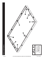
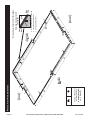
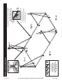
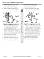
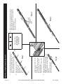
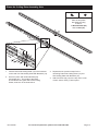
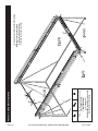
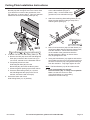
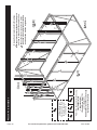
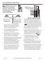
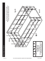
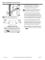
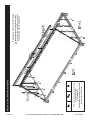
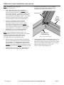
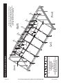
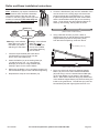
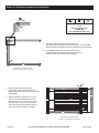
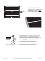
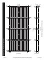
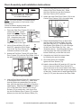
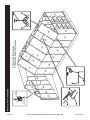
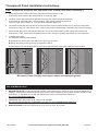
Table of Contents
Safety.......................................................... 3
Specifications.............................................. 4
Assembly..................................................... 5
Maintenance............................................... 29
Warranty..................................................... 32
Parts Lists................................................... 30
WARNING SYMBOLS AND DEFINITIONS
This is the safety alert symbol. It is used to alert you to potential personal injury hazards.
Obey all safety messages that follow this symbol to avoid possible injury or death.
Indicates a hazardous situation which, if not avoided,
will result in death or serious injury.
Indicates a hazardous situation which, if not avoided,
could result in death or serious injury.
Indicates a hazardous situation which, if not avoided,
could result in minor or moderate injury.
Addresses practices not related to personal injury.
Page 2
For technical questions, please call 1-800-444-3353.
Item 93358
IMPORTANT SAFETY INFORMATION
The warnings, precautions, and instructions discussed in this manual cannot cover all possible conditions
and situations that may occur. The operator must understand that common sense and caution are factors,
which cannot be built into this product, but must be supplied by the operator.
Assembly / Installation Precautions
1. Assemble only according to these instructions.
Improper assembly can create hazards.
6. Do not assemble when tired or when under the
influence of alcohol, drugs or medication.
2. Wear ANSI-approved safety goggles and
heavy-duty work gloves during assembly.
7. Product capabilities apply to properly and
completely assembled product only.
3. This unit contains pieces with sharp edges.
The machined edges of the aluminum parts
and the ends of the panel clips may be sharp.
Handle all parts carefully.
8. Locate the Greenhouse on a flat, level, surface.
A concrete foundation is recommended
for a high-quality installation.
4. Keep assembly area clean and well lit.
5. Keep bystanders out of the area during assembly.
9. WARNING: The brass bushings inside the
Rollers of this product contain lead, a chemical
known to the State of California to cause
birth defects (or other reproductive harm).
(California Health & Safety Code § 25249.5, et seq.)
Use / Service Precautions
1. This product is not a toy. Do not allow
children to play in or climb on this product.
Although this greenhouse does include some caps,
there are still some exposed sharp edges.
In addition, protective covers may fall off in time.
Children must be supervised if
allowed near the greenhouse.
3. Use as intended only.
4. Inspect periodically; replace damaged parts
immediately and do not enter greenhouse
if parts are loose or damaged.
5. For your safety, service and maintenance should
be performed regularly by a qualified technician.
2. SNOW/DEBRIS ACCUMULATION HAZARD.
The heavy weight of accumulated snow or other
debris can cause parts of this greenhouse to buckle
suddenly. Do not allow debris to accumulate on
top of the greenhouse. If snowfall is expected,
place additional supports (not provided) underneath
the Crown. NEVER enter a greenhouse
with accumulated debris on top.
SAVE THESE INSTRUCTIONS.
Item 93358
For technical questions, please call 1-800-444-3353.
Page 3
Specifications
Overall Dimensions
1201/2″ W x 1441/2″ L x 123″ H
Window Dimensions
231/4″ W x 311/4″ L
Door Dimensions
751/2″ H x 351/2″ W x 11/4″ Thick
Materials
Aluminum Frame
Transparent Polycarbonate Sheets
Aluminum Thickness
0.038″
Polycarbonate Sheet Thickness
0.165″
Page 4
For technical questions, please call 1-800-444-3353.
Item 93358
Assembly
Read the ENTIRE IMPORTANT SAFETY INFORMATION section at the beginning of this document
including all text under subheadings therein before set up or use of this product.
IMPORTANT–READ THE FOLLOWING CAREFULLY BEFORE PROCEEDING
• The first step in assembly is to assemble a proper base. The greenhouse must be properly
supported to help prevent property damage and injury in the event of strong winds or
inclement weather. Wind and ground conditions may vary from site to site, and may affect
the practicality and effectiveness of anchoring methods substantially. If you have any doubt
regarding the stability of the base/foundation you are to use, consult a professional.
• It is always your responsibility to ensure that the greenhouse is properly anchored. Harbor Freight Tools cannot be held responsible for personal injury, damage to the greenhouse,
or other property damage that occurs as a result of improperly anchoring the greenhouse.
• Be certain to check with local authorities to obtain all required building permits
and to familiarize yourself with any building codes that may apply.
• Decide on a location for the greenhouse. The location should optimally be a
level, well‑lit area that is sheltered from the wind. The door of the greenhouse
should not open towards the prevailing wind, if possible.
IMPORTANT ASSEMBLY TIPS
• Assemble Bolts with their heads facing the outside of the greenhouse, unless stated otherwise. Tighten Nuts (67) only about 1/4 turn past finger-tight; be careful not to overtighten.
• Lay out all parts by number prior to assembly.
• At least two assistants will be necessary during assembly.
• Assemble on a clear, calm day. Wind will damage the Greenhouse and make assembly difficult.
Item 93358
For technical questions, please call 1-800-444-3353.
Page 5
Page 6
For technical questions, please call 1-800-444-3353.
Item 93358
All parts in this phase
are fastened using
32 Base Bolts (68)
and 32 Base Nuts (69).
Phase 1: Base Assembly
Base Assembly Instructions
1. Excavate an area for the base of the greenhouse.
The area must be 10′ 2″ wide by 12′ 2″ long by
5″ deep. The floor of the hole must be level
and square. The diagonal dimensions, from
corner to corner, should each be 15′ 5″.
2. Assemble the Base outside the hole as shown
below. Note that the angled edges of the
Base Plates (43, 44) need to face the corners of
the base. Use Base Bolts (68), Base Nuts (69), and
Connectors (45, 46) to secure the pieces together.
Item 93358
3. With assistance, lower the Base into the hole.
The diagonal dimensions,
from outside corner to outside corner,
must be equal for the base to be square.
4. Fill the hole around the outside of the base with soil.
5. This base will need to be filled with about
40 cubic feet of gravel or another appropriate
fill material (not provided). The gravel should
reach up to about 1″ below the lip of the base.
For technical questions, please call 1-800-444-3353.
Page 7
Page 8
For technical questions, please call 1-800-444-3353.
Item 93358
43 4
All parts in this phase
are fastened using
16 Normal Bolts (65)
and 16 Nuts (67).
44
5
(Rear)
Phase 2: Floor Plate Installation
(Left)
44
6
43
3
3
43
1a
gravel
c
a
Base
Plate
47
4
44
(Front)
2a
a. Slide Connector (47) under lip.
b. Insert Regular Bolt (65).
c. Fasten with Nut (67)
43
44
(Right)
Hold-down Connector (47)
attachment
Floor
Plate
b
Grey parts are in place before this phase.
Floor Plate Installation Instructions
Front Floor
Plate (1a, 2a)
Rear/Side
Floor Plates
(3 – 6)
gravel
outside
greenhouse
Base Plate
(43, 44)
ground
Cross Section
1. When placing the Floor Plates (1a–6) on top of
the Base Plates (43, 44), align them as illustrated
above. The lip should extend slightly over the
edge of the Base Plate and the raised flange with
bolt holes should face inside the greenhouse.
2. Place the Front-Left Floor Plate (1a)
on top of the Base Plate (44). Lay the
Front‑Right Floor Plate (2a) on top of it and line
up the 2 holes where the Plates overlap.
4. Place the Side Floor Plates (4) on the
Side Base Plates (43) on the front-right
and rear left corners as illustrated. Lay the
Upper Side Floor Plates (3) on top so that the
three holes line up where the Plates overlap.
5. Fasten the Side Floor Plates (3, 4) together,
and secure to the Base Plates (43) using
3 Hold-down Connectors (47) on each side
of the greenhouse in the places illustrated;
see illustration and inset on facing page.
6. Lay the Rear-right Floor Plate (6) on top of the
Rear-left Floor Plate (5) so that the 2 holes
line up where the Plates overlap. Fasten the
Rear Floor Plates (5, 6) together through those holes.
7. Place the assembled Rear Floor Plates (5, 6)
on top of the Base Plates (44).
8. Secure the Rear Floor Plates (5, 6)
to the Base Plates (44) using
2 Hold‑down Connectors (47) in the locations
shown; see illustration and inset on facing page.
3. Fasten the Front Floor Plates (1a, 2a) together,
and secure to the Base Plate (44) using a
Hold-down Connector (47) over one of the
Bolts (65), see inset on facing page.
Item 93358
For technical questions, please call 1-800-444-3353.
Page 9
Page 10
65
67
For technical questions, please call 1-800-444-3353.
7
31
79
47
49
5
Parts in this phase
are fastened using
10 Normal Bolts (65),
14 Brace Bolts (66),
2 Double Brace Bolts (78),
and 26 Nuts (67).
47
7
Phase 3: Corner Post Installation
80
4
(Rear)
67
65
Item 93358
(Left)
6
31
7
79
80
49
3
3
80
49
7
79
1a
(Right)
4
a
Base
Plate
2a
79
(Front)
80
7
49
a. Slide Connector (47) under lip.
b. Insert Brace Bolt (66).
c. Slide Strut (79, 80) over Bolt.
d. Fasten with Nut (67)
d
gravel
c
Hold-down Connector (47)
attachment with Strut (79, 80)
Floor
Plate
b
Grey parts are in place before this phase.
Corner Post Installation Instructions
1. There are 4 Corner Posts (7) to be attached
to the Floor Plates (1–6). The end with 2
holes should be at the bottom, as shown in
the illustration in the center of this page.
7. Repeat steps 2 through 6 for the left rear
Corner Post (7) on the left side. Keep
in mind that the connections will be
reversed compared to the right side.
TOP
8. Attach one Corner Post (7) on the outside
of the front left Floor Plates (1a, 3)
using 2 Normal Bolts (65), 2 Hold-down
Connectors (47), and 2 Nuts (67).
66
(Left)
66
78
66
65
2. Attach one Corner Post (7) on the outside of
the right rear Floor Plates (3, 6) using 2 Normal
Bolts (65), 2 Hold-down Connectors (47),
and 2 Nuts (67), see inset - facing page.
49
80
7
31
79
(Front)
67
(Rear)
3. Fasten a Corner Bracket (49) to the top
of the Corner Post (7) over the Rear Floor
Plate (6) using one Normal Bolt (65) for
now. Install it angled up towards the center
of the greenhouse, as shown above.
4. Install a Double Brace Bolt (78) through the bottom
hole of the Corner Bracket (78). Place a Rear
Brace (31) over it with the arrow pointing towards
the Bolt. Also place Front/Rear Diagonal Strut (79)
over the Bolt, and thread on Nut (67) hand-tight.
5. Fasten a Side Diagonal Strut (80) to
the free top hole on the Corner Post (7)
using Brace Bolt (66) and Nut (67).
6. Fasten Struts (79, 80) to Floor Plates using
Brace Bolts (66), Hold-down Connectors (47),
and Nuts (67), see inset on facing page.
Allow Rear Braces (31) to hang free.
7
(View from inside greenhouse.)
Corner Post (7)
(View from inside greenhouse.)
79
67
67
67
67
(Right)
49
80
9. Insert a Brace Bolt (66) through the second
hole from the top of the Corner Post (7) over the
Front Floor Plate (1a). Place the bottom hole
of the Corner Bracket (49) over the Bolt with it
angled up towards the center of the greenhouse,
as shown above. Secure it using a Nut (67).
10. Fasten a Side Diagonal Strut (80) to the top
hole on the Corner Post (7) over the Side Floor
Plate using a Brace Bolt (66) and Nut (67).
11. Secure the Struts (79, 80) to the Floor Plates
using Brace Bolts (66), Hold-down Connectors
(47), and Nuts (67), see inset on facing page.
12. Repeat steps 8 through 11 for the right
front Corner Post (7) on the right side.
Keep in mind that the connections will be
reversed compared to the left side.
BOTTOM
Item 93358
For technical questions, please call 1-800-444-3353.
Page 11
Page 12
For technical questions, please call 1-800-444-3353.
Item 93358
65
65
,2
27
Step 2
3. Slide the Bolt heads on the Front-left
Ceiling Plate (24) into the slot of the
Right Door Rail (27) from the left edge until
it rests against the Front-right Ceiling
Plate (25).
25
Tighten the 2 right-most
Nuts on the Ceiling Plate.
26
Step 1
Ceiling Plate (25) until the right end
is flush, as shown.
The illustration in the center of this
page shows how to slide the Rail
over the Bolt heads.
Tighten the Nuts on those 2 Bolts.
65
65
2. Slide the slot on the Right
Door Rail (27) over
the heads of the 2
Bolts on the
Front24
right
7
1. Insert Normal Bolts (65) through all holes in the
front of the Front Ceiling Plates (24, 25), as
shown. Thread a Nut (67) onto each
Bolt, but leave all Nuts loose for now.
25
Phase 4a: Ceiling Plate Assembly, Front
65
65
5
,2
24
26
Parts in this phase
are fastened using
7 Normal Bolts (65)
and 7 Nuts (67).
24
24
Step 4
o
tw
se ing
e
th lid
te n fte r s
h
g
Ti ts a
Nu
27
Step 3
27
25
25
4. Slide the slot on the Left Door Rail (26) over the
heads of the remaining three Bolts in the Frontleft Ceiling Plate (24) until it presses against the
Right Door Rail (27).
Tighten the remaining Nuts.
Phase 4b: Ceiling Plate Assembly, Side
Parts in this phase
are fastened using
a total of
12 Normal Bolts (65)
and 12 Nuts (67).
12
13
13
65
13
13
67
67
67
67
65
12
65
65
65
12
12
67
65
67
1. Insert a Plain Side Ceiling Plate (13) in the brackets
on the end of a Side Ceiling Plate with Brackets (12).
2. Secure in place with 6 Normal Bolts (65)
and 6 Nuts (67). The heads of the Bolts
should all face the gutter side of the Ceiling
Plates, as shown in the inset above.
Item 93358
3. Repeat the two previous steps for the
remaining Plain Side Ceiling Plate (13) and
Side Ceiling Plate with Brackets (12).
4. Attach an End Cap (72) to the top outer corner
of each Corner Post (7) at this point.
For technical questions, please call 1-800-444-3353.
Page 13
Page 14
For technical questions, please call 1-800-444-3353.
Item 93358
80
(Rear)
31
Parts in this phase are fastened using
2 Normal Bolts (65),
8 Brace Bolts (66),
and 10 Nuts (67).
Additional Bolts and Nuts are already
in place before this phase.
7
13
31
48
48
Phase 5: Ceiling Plate Installation
7
(Left)
12
80
12
80
7
80
24
,2
(Front)
(Right)
13
5
Means that the nearby Bolt
will be removed and then reattached at the same location.
7
Grey parts are in place before this phase.
Ceiling Plate Installation Instructions
1. Insert one Normal Bolt (65) through the Corner
Bracket (49) and the upper hole in the Corner Post
(7) at both front corners of the greenhouse, from
the inside out, as shown above. This is for the later
attachment of the Front Ceiling Plate (24-27).
4. Attach the Front Ceiling Plate (24, 25)
to the 2 Normal Bolts (65) put in
place in step 1 on the outside of the
greenhouse, note orientation at right.
66 66
5. Attach the remaining Side Ceiling Plate (12, 13)
along the other side according to steps 2 & 3,
with the gutter opening up.
49
67
7
31
80
(Left)
(View from inside greenhouse.)
2. To attach one end of a Side Ceiling Plate (12, 13):
a. Remove the Nut (67) where the Side Diagonal
Strut (80) connects to the Corner Post (7) in
one corner, marked A in the illustration above.
b. Temporarily disconnect that
Side Diagonal Strut (80) from the
Brace Bolt (66), but leave the Bolt in place.
c. Orient the gutter opening up as shown above.
d. Place the Side Ceiling Plate (12, 13) then
the Side Diagonal Strut (80) on the end of
the Bolt, and secure with a Nut (65).
3. Secure the other end of that
Side Ceiling Plate (12, 13) similarly.
Item 93358
67 67
A
(Front)
79
48
31
67 67
66 66
12
48
(View from
inside
greenhouse.)
6. Bolt 2 Post Connectors (48) to a Rear Brace (31)
using Brace Bolts (66) through their bottom holes,
from the outside in. Place Post Connectors
on the outside of the greenhouse with the
flat side against the Brace, as shown above.
Only finger tighten for now.
7. Swing the Rear Braces (31) together and bolt the
second Brace to the second from bottom holes on
the Post Connectors (48), using Brace Bolts (66)
from the outside in. Only finger tighten for now.
Note: The Rear Braces (31) will be under tension.
8. If you cannot attach the second
Post Connector (48), or if they are not parallel:
Make sure that the arrows on both
of the Rear Braces (31) are pointing
towards the Corner Posts (7).
For technical questions, please call 1-800-444-3353.
Page 15
For technical questions, please call 1-800-444-3353.
80
66,78,66
14
14
66(x4)
13
31
Parts in this phase are fastened using
8 Normal Bolts (65),
2 Brace Bolts (66),
4 Double Brace Bolts (78),
and 14 Nuts (67).
Additional Bolts and Nuts are already
in place before this phase.
44 Brace Bolts (66)
are inserted into Posts
during this phase for
use in phase 7.
5
16
66(x2)
48
4
14
66(x4)
14
66(x4)
48
(Rear)
81
Phase 6: Post Installation
31
14
66(x4)
6
(Left)
17
66(x2)
14
66(x4)
80
14
12
81
66,78,66
3
3
80
81
Page 16
Item 93358
14
14
66(x4)
66,78,66
12
14
66(x4)
14
66(x4)
4
14
81
66,78,66
(Front)
80
13
(Right)
Means that the bolt underneath will be
loosened, a Post will slide over the bolt
head, and then it will be re-tightened.
Means that the nearby Bolt will be removed
and then re-attached at the same location.
Grey parts are in place before this phase.
Post Installation Instructions
Note: All Posts (14, 16, 17) in this
phase require extra Bolts to be
inserted into their slot before
assembly. The small numbers
under the main part number on the
facing page are the type and
number of hardware.
See the examples below:
17
66(x2)
Post Part Number
Inserted Bolt
Part Numbers
Meaning: Insert 2 Brace
Bolts (66) into the
Rear Right Post (17)
before attaching it.
Side Pos
t (14) mu
st extend
no farthe
r than ha
lfwa
the Post
Connecto y up
r (48).
66
66
31
14
31
14
66,78,66
Meaning: Insert a Brace
Bolt (66), then a Double
Brace Bolt (78), then
another Brace Bolt (66)
into this Side Post (14)
before attaching it.
1. Loosen a Bolt on one of the Side Floor
Plates (3,4) in an attachment location
as shown. Slide the slot in a Side Post
(14) over the head of that Bolt.
2. Insert the required Bolts (See note
above and illustration on facing page)
into the slot in the Side Post.
3. Attach the top of the Side Post (14) to
the Ceiling Plate (12, 13), using a Normal
Bolt (65) in the slot or using the Bolt
already in place for the center Post.
4. Repeat above steps for all 10 Side Posts (14)
on the left and right sides of the greenhouse.
5. Slide a white Bushing (81) over all 4
inserted Double Brace Bolts (78). Place
the center hole of each Side Diagonal
Strut (80) over the end of each Double
Brace Bolt and secure with a Nut (67).
6. Loosen a Bolt on the Rear Floor Plate
(5, 6) in a location that a Side Post (14)
attaches, and slide a Side Post over
the head of that Bolt. Insert 4 Brace
Bolts (66) into the slot of that Post.
Item 93358
48
(View from outside greenhouse.)
7. Remove the 2 Brace Bolts (66) connecting
the Post Connector (48) near that Side
Post. Slide the heads of those Bolts into the
Side Post and insert them through the Post
Connector. Align the top of the Post with the
center of the Connector as shown above, and
press it in place. Reattach the Rear Braces
(31) to the Brace Bolts (66) and secure them.
8. Repeat steps 6 & 7 for another Side
Post (14) and Post Connector (48).
9. Loosen the Bolts (66) where the Rear
Diagonal Struts (79) connect to the Rear Floor
Plate (5, 6). Slide the slot in the Rear-Left
Post (16) over the head of the left Bolt and
the Rear-Right Post (17) over the right Bolt.
10.The slanted ends of the Posts must be
on top and slant towards the center of
the greenhouse. Retighten the Bolts.
11.Slide 2 Brace Bolts (66) into the slot
of each Rear Post (16, 17).
12.Slide one more Brace Bolt (66) into the top
of each Rear Post. Attach the Rear Posts
to the Rear Braces (31) using those Bolts.
13.The frame should now rest square. Measure
diagonally from corner to corner at the top. If
the measurements are not equal, adjust the
frame as needed until square. Some Nuts
(67) may need to be loosened to adjust the
frame. Tighten all Nuts after adjustment.
For technical questions, please call 1-800-444-3353.
Page 17
Page 18
For technical questions, please call 1-800-444-3353.
Item 93358
16
14
31
31
Parts in this phase are fastened using
2 Normal Bolts (65),
20 Brace Bolts (66),
and 66 Nuts (67).
Additional Bolts and Nuts are already
in place before this phase.
7
Phase 7: Brace Installation
14
80
30
30
14
14
(Rear)
31
31
14
(Left)
17
7
80
14
14
30
30
30
14
30
14
80
7
32
32
14
28
30
80
14
14
29
(Front)
5
,2
24
30
(Right)
32
32
7
Means that the nearby Bolt will be removed
and then re-attached at the same location.
Grey parts are in place before this phase.
(79, 8
0)
2. Using Brace Bolts (66), connect the Front
Braces (32) between the Corner Posts (7) and
the Doorway Posts (28, 29). Install Braces
inside Posts but outside Struts, as shown
in the diagram at the top of this page.
Strut
Note: Install the Braces on the walls so that they are
level. If the frame is level and all Braces are level,
the Braces should not interfere with one another.
Corner Post (7)
Post (14, 16, 17)
Brace Installation Instructions
e
ac
Br - 32)
(30
Note: All Braces are installed inside the Posts,
but outside the Struts. See diagram above,
shown from inside the greenhouse facing out.
to (right)
Corner
Post (7)
(Outside greenhouse)
29
(Doorway)
to (left)
Corner
Post (7)
28
(Inside greenhouse)
(View from above.)
1. Using a Normal Bolt (65) at top and the Brace
Bolt (66) already in place at the bottom for each,
attach the Left and Right Doorway Posts (28, 29)
to the outside of the Front Floor Plates (1a, 2a)
and to the inside of the Front Ceiling Plates (24,
25). Install the Posts with the cut-outs at top and
oriented as shown in the illustration above.
Item 93358
3. Connect the 4 remaining Rear Braces (31) onto
the rear wall as shown on the facing page, with
the arrows pointing towards the Corner Posts (7).
Secure in place using Brace Bolts (66) at the Corner
Post and the inserted Brace Bolts in the remaining
holes. Install Braces inside Posts but outside Struts,
as shown in the diagram at the top of this page.
4. Connect 4 Side Braces (30) onto each side wall
as shown on the facing page, with the arrows
pointing towards the Corner Posts (7). Secure in
place using Brace Bolts (66) at the Corner Post and
the inserted Brace Bolts in the remaining holes.
Install Braces inside Posts but outside Struts, as
shown in the diagram at the top of this page.
5. Place the Gutter End Caps (73) onto the ends of the
Side Ceiling Plates (12, 13) oriented with a gap in
the bottom to allow water to drain out of the gutters.
For technical questions, please call 1-800-444-3353.
Page 19
Page 20
For technical questions, please call 1-800-444-3353.
Item 93358
13
14
48
19
14
Parts in this phase are fastened using
36 Normal Bolts (65)
and 36 Nuts (67).
Additional Bolts and Nuts are already
in place before this phase.
8 16
(Rear)
18
Phase 8: Gable and Crown Installation
17
(Left)
9
10
12
12
28
22
11
9
20
13
2
5
8
29
23
(Front)
2
4,
21
(Right)
Means that the bolt underneath will be
loosened, a Post will slide over the bolt
head, and then it will be re-tightened.
Grey parts are in place before this phase.
Gable and Crown Installation Instructions
Note: Leave Bolts (65) finger tight
until step 5 of this phase.
1. Use 1 Normal Bolt (65) each to attach the
Front Gable Posts (20-23) to the outside top of
the Front Ceiling Plates (24, 25) in the positions
shown on facing page. The bottoms of the 2 outer
Front Gable Posts (22, 23) will be secured using
the Normal Bolts (65) already in place. The sloped
ends of the Posts must be on the top and slant
upward toward the center of the greenhouse.
5. Press the Crown Beams (8, 9) down against
the tops of the Posts (16-23) while tightening
all Bolts (65) to secure them in place.
Crown (10, 11)
Lefthanded
Crown
Beam (9)
2. Insert 2 Normal Bolts (65) into the slot in
each Rear Gable Post (18, 19), and use
those Bolts to attach them to the top 2 holes
of the Post Connectors (48) on the outside.
Once again, the sloped ends of the Posts must
be on the top and slant upward toward the center
of the greenhouse. The bottoms of those Rear
Gable Posts (18, 19) must be pressed down
flat against the tops of the Side Posts (14).
Note: The only difference between Right- and
Left‑Handed Crown Beams is the location of the holes.
The Beam edges with 3 drilled holes should
align with the Side Ceiling Plate (12, 13) and
the edges with 4 holes should point down.
3. Attach the Right- and Left-Handed Crown Beams
(8, 9) to the Greenhouse using 5 Normal Bolts (65)
for each Beam. The angled edges should meet at
the top of the roof. The Beams are placed on the
outside of the Ceiling Plates (12, 13) and the Corner
Brackets (49) and on the inside of the Posts (16-23).
Right-handed
Crown Beam (8)
(View from underneath.)
6. With assistance, raise the completed Crown (10, 11)
up underneath the tops of the Crown Beams (8, 9),
and bolt it in place on each end to the bottom of the
Beams using 2 Normal Bolts (65) as shown above.
7. Attach an End Cap (72) to the top outer
corner of each Crown Beam (8, 9).
4. Assemble the Front Crown (11) to the brackets on
the Rear Crown (10) using 6 Normal Bolts (65).
Item 93358
For technical questions, please call 1-800-444-3353.
Page 21
Page 22
For technical questions, please call 1-800-444-3353.
Item 93358
12
15
66,65
Parts in this phase are fastened using
24 Normal Bolts (65),
20 Brace Bolts (66),
44 Nuts (67),
and 8 Window Screws (71).
Additional Bolts and Nuts are already
in place before this phase.
8
(Rear)
Phase 9: Rafter and Brace Installation
15
66,66,65
30
42
50,71(x2)
30
9
42
(Left)
15
66,66
50,71(x2)
10
13
15
13
66,66,65
15
66,65
15
11
15
66,65
30
42
9
15
12
66,66,65
42
50,71(x2)
66,66
15
(Right)
50,71(x2)
66,66,65
(Front)
30
15
66,65
8
Means that the bolt underneath will be
loosened, a Rafter will slide over the bolt
head, and then it will be re-tightened.
Grey parts are in place before this phase.
Rafter and Brace Installation Instructions
Note: All Rafters (15) require extra Bolts to
be inserted into their slot before assembly.
The small numbers under the main part
number on the facing page are the type and
number of hardware in the order they are
inserted from the TOP of the Rafter.
See the examples below:
15
66(x2)
Rafter Part
Number
Inserted Bolt
Part Numbers
50
15
66,66,65
Meaning: Insert 2 Brace Meaning: Insert 2 Brace
Bolts (66) into the top of
Bolts (66), then a
this Rafter (15) before
Normal Bolt (65) into
attaching it to the frame.
the top of this Rafter
(15) before attaching
it to the frame.
1. Insert the required Bolts (See note above
and illustration on facing page) into the
slot in one of the Rafters (15).
2. Attach the Rafter (15) to the Ceiling Plate (12,
13) and the Crown (10, 11), using Normal
Bolts (65) in the slot or using the Bolts (65)
already in place for the center Rafters.
3. Make sure the Rafter (15) is completely seated over
the Normal Bolts (65) on each end before tightening.
4. Repeat above steps for all 10 Rafters (15).
Item 93358
5. Connect 4 Side Braces (30) onto the underside of the
roof as shown on the facing page, with the arrows
pointing towards the Crown Beams (8, 9). Secure
in place using Brace Bolts (66) at the Crown Beam
and the inserted Brace Bolts (66) in the remaining
holes. Finger tighten first and install the Braces so
that they are touching, side-by-side as shown.
42
(View from underneath.)
6. Using 2 Window Screws (71) each, attach a
Window Stop (50) on the flat side of each Window
Support Beam (42) with its tab pointing away
from the bolt slot openings, as shown above.
to Crown (10, 11)
15
15
42
65
65
30
(View from underneath.)
7. Place one of the bolt slots on a Window Support
Beam (42) over one of the inserted Normal Bolts
(65) and swing it over the inserted Normal Bolt (65)
on the other Rafter (15) as shown in the diagram
above. Note that the Window Stop (50) and flat side
of the Window Support Beam (42) are both facing the
inside of the greenhouse. Thread Nuts (67) onto the
Normal Bolts (65) and finger tighten them for now.
For technical questions, please call 1-800-444-3353.
Page 23
Phase 10: Window Assembly and Installation
67
39
38
67
65
Parts in this phase are fastened
using
16 Normal Bolts (65),
16 Nuts (67),
and 8 Window Screws (71).
65
39
65
1. Attach the Side Window Frames (39) to the
Top Window Frame (38), as shown to the left. The threaded
shafts of the Bolts should extend out the bottom of the window.
2. Insert Normal Bolts (65) into the holes at other
end of the Side Window Frames (39), so that the
threads stick out the bottom of the window.
38
67
39
65
65
(View from underneath
window, flat side of pieces.)
39
3. Remove the protective film from
both sides of the Window Pane (61).
Slide the Window Pane (61) into the threesided frame.
4. Slide the Bottom Window Frame (40)
onto the 2 Normal Bolts (65) and the
Window Pane (61). Secure it in place
with Nuts (67). Press on the heads of
the Bolts through the Window Pane to
allow the Nuts to thread on properly.
65
67
40
61
38
67
39
65
(View from underneath
window, flat side of pieces.)
Page 24
For technical questions, please call 1-800-444-3353.
Item 93358
39
40
38
61
41
5. Attach the Window Brace (41) to the
Bottom Window Frame (40) using 2
Window Screws (71). The holes on the
Window Brace (41) should face away
from the window, as shown below.
71
39
Top Window
Frame (38)
Crown
(10, 11)
6. Hold the assembled window level with the ground at the outer
edge of the Crown (10, 11). Slide the top edge of the Top
Window Frame (38) into the slot at the top of the Crown (10, 11),
see illustration to the left. Align the window with the Window
Brace (41) underneath it. Slide the window into place over the
Window Support Beam (42). Gradually lower it into place.
7. Loosen the Nuts (67) holding the Window Support
Beam (42) in place and slide the Window Support Beam
(42) up to touch the window. Secure it in place.
(View from end of Crown.)
Item 93358
8. Repeat the steps in this phase for all four windows.
For technical questions, please call 1-800-444-3353.
Page 25
70
Page 26
64
37
51
(bottom)
51
For technical questions, please call 1-800-444-3353.
64
(front)
36
64
36
70
64
70
65
70
70
(top)
67
(Profiles exaggerated for clarity.)
64
33
33
64
36
70
(back)
70
64
37
70
36
70
36
70
36
70
70
34, 35
70
70
33
64
70
Phase 11: Door Assembly and Installation
(top)
34
35
(bottom)
51
Item 93358
Door Assembly and Installation Instructions
5. Remove the protective film from both
sides of four Door Panels (64). Slide
the Door Panels into the door between
the Door Frame (35-37) pieces.
Parts in this phase are fastened using
8 Normal Bolts (65), 8 Nuts (67),
and 40 Door Screws (70).
6. Attach the other Side Door Frame (33) to the
Center Door Frames (36) in the same way.
Note: The Door Screws (70) thread directly
into the round portions in the center of the
door frames.
Leave all Screws slightly loose until
the door is mounted on the rail.
33
1a
1. Place the Side Door Frame (33) with the
rubber flap down. Attach
three Center Door Frames
(36) to the Side Door Frame
(33). Assemble them with
the rounded portion facing
the front (away from the
flap), as shown to the right.
(side view)
34
65
67
2. Using 2 Normal Bolts (65) and 2
Nuts (67), attach the Door Slider
(34) to the Top Door Frame (35)
oriented as shown to the right.
51
35
3. Attach the Top Door Frame (35) to the Side
Door Frames (33) with the Door Slider (34) at
top and the rounded portion facing the front.
7. Raise the assembled Door up and insert
the first roller of its Door Slider (34) onto
the Door Rail (26, 27). Carefully align the
first Bottom Door Slider (51) over the edge
of the Front Floor Plate (1a, 2a) – see
illustration above. Carefully slide the door
over and align the other top Roller and
bottom Slider as you did the first ones.
8. Assemble and install the second door
by following the previous steps.
9. Once both doors are installed,
tighten all Door Screws (70).
10.Install a Normal Bolt (65) and Nut (67) into the
hole on the end of each Door Rail (26, 27),
and in the hole on the end of each Front Floor
Plate (1a, 2a) to prevent the doors from sliding
off the rails. Attach the Left and Right Rail End
Caps (74,75) onto the ends of the Door Rails.
(view from behind)
4. Insert a Door Bottom Slider (51) into each end
of the Bottom Door Frame (37). Make sure
that the Sliders are assembled the correct
way, with the gap facing the back of the door –
see diagram. Attach the Bottom Door Frame
(37) to the Side Door Frames (33) using 2
Screws (70) on each side – the one on the
top into the Bottom Door Frame (37) and the
bottom one into the Door Bottom Slider (51).
Item 93358
For technical questions, please call 1-800-444-3353.
Page 27
Page 28
For technical questions, please call 1-800-444-3353.
Item 93358
Outside
Greenhouse
52
X
X
X
X
X
X
X
X
Inside
Greenhouse
58
56/57
X
X
X
X
Phase 12: Panel Installation
X
X
X
X
X
X
X
X
X
X
X
X
X
X
X
X
X
X
X
X
X
X
X
X
X
X
X
X
X
X
X
X
X
X
X
X
X
X
X
X
X
X
X
X
X X
X
X
X
X
X
X
X
X = Panel Clip (53) Location
O = Panel Connector (52) Location
X
X
X
X
X
X
X
X
X
X
X
X
X
XX
X
X
X
X
X
X
X
X
X
X
X
X
X
X
X
X
X
X
X
X
X
X
X
X
X
X
X
X
X
X
X
X
X
X
X
Transparent Panel Installation Instructions
Note: Remove the protective film from both sides of each panel before installing it.
1. Panel Clips (53) are used to secure the Transparent Panels in place on the
Greenhouse, their locations are marked with X on the facing page.
2. The Roof Panels (60) and the Roof Window Panel (59) will need to be placed as shown
in the insets on the facing page. The top edges of these panels need to be placed up
under the edge of the Crown (10, 11) or the Window Support Beam (42).
3. The Panel Connectors (52) are used to connect the Rear Top and Center Panels (56, 57) to the top of the Wall
Panels (58) in the rear of the Greenhouse. Refer to the locations marked with O and the inset on the facing page.
4. One at a time, place each Transparent Panel (55 – 64) in its proper location on the Ceiling and Frame of the
Greenhouse. Then, secure the Transparent Panel in place, using the quantity and location of Panel Clips (53).
5. To attach Panel Clips,
see illustration and instructions below:
A)Place the two loose ends of the Clip into the groove in the frame
B)Swing the center portion of the Clip up against the Panel
C)Two edges of the Clip swing under the edge of the panel and the center edge holds the panel in place.
Be careful, Panel Clip (53) ends may be sharp and may spring back!
Use and Maintenance
1. BEFORE EACH USE, inspect the general condition of the Greenhouse. Check for loose screws, misalignment or
binding of moving parts, cracked or broken parts, and any other condition that may affect the safe operation of the
Greenhouse. If a problem occurs with the Greenhouse, have it corrected before further use.
Do not use damaged equipment.
2. TO CLEAN: Wipe with a damp cloth, using a mild detergent.
Do not use cleaners that are combustible, corrosive, or not compatible with aluminum.
3. WHEN STORING: Keep the Greenhouse in a box and in a clean, dry location.
Item 93358
For technical questions, please call 1-800-444-3353.
Page 29
PLEASE READ THE FOLLOWING CAREFULLY
THE MANUFACTURER AND/OR DISTRIBUTOR HAS PROVIDED THE PARTS LISTS IN THIS DOCUMENT
AS A REFERENCE TOOL ONLY. NEITHER THE MANUFACTURER OR DISTRIBUTOR MAKES ANY
REPRESENTATION OR WARRANTY OF ANY KIND TO THE BUYER THAT HE OR SHE IS QUALIFIED TO
MAKE ANY REPAIRS TO THE PRODUCT, OR THAT HE OR SHE IS QUALIFIED TO REPLACE ANY PARTS
OF THE PRODUCT. IN FACT, THE MANUFACTURER AND/OR DISTRIBUTOR EXPRESSLY STATES
THAT ALL REPAIRS AND PARTS REPLACEMENTS SHOULD BE UNDERTAKEN BY CERTIFIED AND
LICENSED TECHNICIANS, AND NOT BY THE BUYER. THE BUYER ASSUMES ALL RISK AND LIABILITY
ARISING OUT OF HIS OR HER REPAIRS TO THE ORIGINAL PRODUCT OR REPLACEMENT PARTS
THERETO, OR ARISING OUT OF HIS OR HER INSTALLATION OF REPLACEMENT PARTS THERETO.
Parts Lists
Lengths given are rounded to the nearest inch. Hardware lengths are approximate.
PART
DESCRIPTION
Q’TY
PART
DESCRIPTION
Q’TY
1a
Front-Left
Floor Plate
2’ 8”
1
19
Rear-Right
Gable Post
2’ 7”
1
2a
Front-Right
Floor Plate
7’ 3”
1
20
Front Center-Left
Gable Post
2’ 8”
1
3
Upper Side
Floor Plate
6’
2
21
Front Center-Right
Gable Post
2’ 8”
1
4
Side Floor Plate
6’
2
22
Front-Left
Gable Post
1’ 5”
1
5
Rear-Left
Floor Plate
4’ 11”
1
23
Front-Right
Gable Post
1’ 5”
1
6
Rear-Right
Floor Plate
4’ 11”
1
24
Front-Left
Ceiling Plate
7’ 5”
1
7
Corner Post
6’ 6”
4
25
Front-Right
Ceiling Plate
2’ 3”
1
8
Right-handed
Crown Beam
5’ 10”
2
26
Left Door Rail
4’ 10”
1
9
Left-handed
Crown Beam
5’ 10”
2
27
Right Door Rail
4’ 10”
1
10
Rear Crown
with Brackets
5’ 9”
1
28
Left Doorway
Post
6’ 6”
1
11
Front Crown
5’ 10”
1
29
Right Doorway
Post
6’ 6”
1
12
Side Ceiling Plate
with Brackets
5’ 9”
2
30
Side Brace
7’ 9”
12
13
Plain Side
Ceiling Plate
5’ 10”
2
31
Rear Brace
5’ 10”
6
14
Side Post
6’ 6”
12
32
Front Brace
2’
4
15
Rafter
5’ 9”
10
33
Side Door Frame
6’ 3”
4
16
Rear-Left Post
7’ 9”
1
34
Door Slider
2’ 10”
2
17
Rear-Right Post
7’ 9”
1
35
Top Door
Frame
2’ 10”
2
18
Rear-Left
Gable Post
2’ 7”
1
36
Center Door
Frame
2’ 10”
6
Page 30
For technical questions, please call 1-800-444-3353.
Item 93358
Lengths given are rounded to the nearest inch. Hardware lengths are approximate.
PART
DESCRIPTION
Q’TY
PART
DESCRIPTION
Q’TY
37
Bottom Door
Frame
2’ 10”
2
60
Roof Panel
1’ 11”
x 5’ 9”
8
38
Top Window
Frame
1’ 11”
4
61
Window Pane
1’ 11”
x 2’ 6”
4
39
Side Window
Frame
2’ 5”
8
62
Front Corner
Panel
1’ 11”
x 1’ 4”
2
40
Bottom Window
Frame
1’ 11”
4
63
Front Side Panel
2’ x
6’ 5”
2
41
Window Brace
10”
4
64
Door Panel
1’ 5” x
2’ 10”
8
42
Window Support
Beam
2’
4
65
Normal Bolt
M6 x
3/ ”
8
141
43
Side Base Plate
5’ 11”
4
66
Brace Bolt
M6 x
3/ ”
4
108
44
Front/Rear Base
Plate
4’ 11”
4
67
Nut
M6
255
45
Base Plate Corner
Connector
4
68
Base Bolt
1/ ” x
4
3/ ”
8
32
46
Base Plate End
Connector
4
69
Base Nut
1/ ”
4
32
47
Hold-down
Connector
25
70
Door Screw
4.3 x
3/ ”
4
40
48
Post Connector
2
71
Window Screw
4.0 x
5/ ”
8
16
49
Corner Bracket
4
72
End Cap
8
50
Window Stop
4
73
Gutter End Cap
4
51
Door Bottom
Slider
4
74
Left Rail End Cap
1
52
Panel Connector
6
75
Right Rail End
Cap
1
53
Panel Clip
260
76
Spanner Wrench
1
54
Peak Cap
2
77
Hex Wrench
1
55
Rear Side Panel
1’ 11”
x 7’ 9”
2
78
Double Brace Bolt
M6 x
1”
6
56
Front/Rear Top
Panel
1’ 11”
x 2’ 7”
4
79
Front/Rear
Diagonal Strut
6’ 7”
4
57
Front/Rear Center
Panel
1’ 11”
x 3’ 3”
2
80
Side Diagonal
Strut
7’ 7”
4
58
Wall Panel
1’ 11”
x 6’ 5”
15
81
Bushing
Ø.5” x
.4”
4
59
Roof Window
Panel
1’ 11”
x 3’ 4”
4
Item 93358
For technical questions, please call 1-800-444-3353.
Page 31
Limited 90 Day Warranty
Harbor Freight Tools Co. makes every effort to assure that its products meet high quality and durability standards,
and warrants to the original purchaser that this product is free from defects in materials and workmanship for the
period of 90 days from the date of purchase. This warranty does not apply to damage due directly or indirectly,
to misuse, abuse, negligence or accidents, repairs or alterations outside our facilities, criminal activity, improper
installation, normal wear and tear, or to lack of maintenance. We shall in no event be liable for death, injuries
to persons or property, or for incidental, contingent, special or consequential damages arising from the use of
our product. Some states do not allow the exclusion or limitation of incidental or consequential damages, so the
above limitation of exclusion may not apply to you. THIS WARRANTY IS EXPRESSLY IN LIEU OF ALL OTHER
WARRANTIES, EXPRESS OR IMPLIED, INCLUDING THE WARRANTIES OF MERCHANTABILITY AND FITNESS.
To take advantage of this warranty, the product or part must be returned to us with transportation charges
prepaid. Proof of purchase date and an explanation of the complaint must accompany the merchandise.
If our inspection verifies the defect, we will either repair or replace the product at our election or we may
elect to refund the purchase price if we cannot readily and quickly provide you with a replacement. We will
return repaired products at our expense, but if we determine there is no defect, or that the defect resulted
from causes not within the scope of our warranty, then you must bear the cost of returning the product.
This warranty gives you specific legal rights and you may also have other rights which vary from state to state.
Record Serial Number Here:
Note: If product has no serial number, record
month and year of purchase instead.
Note: Some parts are listed and shown for
illustration purposes only, and are not available
individually as replacement parts.
3491 Mission Oaks Blvd. • PO Box 6009 • Camarillo, CA 93011 • (800) 444-3353