1
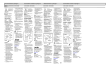
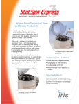
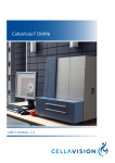
2
Operator’s Manual
Operator’s Manual
for
2
Cytocentrifuge System
Model Number M801-22
Product Number:
CF02
CytoFuge 2 for 100-240 VAC, 50/60 Hz
Patent Numbers 5,480,484 and 5,679,154. Foreign patents pending.
StatSpin and CytoFuge are registered trademarks of StatSpin Inc.
Copyright 1998
Printed in U.S.A.
StatSpin® Inc
85 Morse Street
Norwood, Massachusetts
02062 USA
telephone
toll-free (USA only)
telefax
781-551-0100
800-782-8774
781-551-0036
TABLE OF CONTENTS
1.0
INTRODUCTION
Page
1
2.0
UNPACKING & INSTALLATION
2.1
Check for damage
2.2
Check package for complete contents
2.3
Installing the CytoFuge 2
2.4
Power connection
1
1
2
2
SAFETY FEATURES
3.1
Symbols and definitions
3.2
Cover interlock system
3.3
Manual latch
3.4
Opening & closing the cover
3.5
Cover interlock by-pass
3
4
4
4
4
WORKING WITH CytoFuge 2
4.1
Abbreviated instructions for use
4.2
CytoFuge rotor
4.3
Removal of CytoFuge rotor
4.4
CytoFuge Cell Concentrators
4.5
Assembly of Cell Concentrators
4.6
Installing Cell Concentrators in the Rotor
4.7
Adding sample to the Cell Concentrator
4.8
3-well concentrator
4.9
1-well concentrator
4.10
Disassembly of cell concentrator
4.11
CytoFuge Filter Concentrator
4.12
Assembly of Filter Concentrator
4.13
Installing Filter Concentrators in the rotor
4.14
Adding sample to the Filter Concentrator
4.15
Disassembly of Filter Concentrators
5
5
6
7
8
8
8
9
9
9
11
11
12
12
12
SAMPLE REQUIREMENTS AND INSTRUMENT SETTINGS
5.1
Starting sample concentration
5.2
Sample volume
5.3
Preconcentration of samples
5.4
Sample dilution
5.5
CytoFuge 2 speed and time settings
13
13
14
14
14
3.0
4.0
5.0
6.0
CONTROLS & INDICATORS
6.1
Controls
- “start” button
- “stop/open” button
- “time” selector
- “speed” selector
- “power” indicator
6.2
Audible Indicators
Normal Function Codes
Malfunction Codes
15
15
7.0
MAINTENANCE
7.1
Cleaning
7.2
Checking the rotor speed
16
17
17
8.0
SPECIFICATIONS
17
9.0
SERVICE
18
10.0
REFERENCES
18
UNIVERSAL PRECAUTIONS
Universal Precautions should be followed on all specimens, regardless
of whether a specimen is known to contain an infectious agent. Universal Precautions have been stated by Center for Disease Control in 1987
and updated in 1988 and are reprinted in National Committee for Clinical
Laboratory Standards approved guidelines, “Clinical Laboratory Safety;
Approved Guideline.” (see references)
1.0
INTRODUCTION
The CytoFuge 2 is a microprocessor-controlled cell preparation system which uses centrifugal force to deposit cells onto microscope slides. Samples are centrifuged in reusable or disposable gasket-sealed chambers (Cell Concentrators), or in disposable chambers which include a bibulous material to absorb and capture suspension fluid during
cytocentrifugation (Filter Concentrators).
A four-position rotor with transparent cover is supplied as standard equipment. The
system is designed to be operated on a laboratory bench or, if potentially biohazardous
material is processed, in a biological safety cabinet. A cover interlock system prevents
operation until the centrifuge cover is securely latched, and prevents access to spinning
parts until the rotor has come to a complete stop. Speeds from 600 rpm to 4400 rpm
and cycle times from 2 minutes to 30 minutes may be selected. Automatic acceleration
rate control and dynamic braking are included to protect delicate samples.
FOR IN VITRO DIAGNOSTIC USE.
U.S. Patent Nos. 5,480,484 & 5,679,154. Foreign patents pending.
2.0
UNPACKING & INSTALLATION
2.1
Check for damage
The CytoFuge 2 and its accessories are delivered in one carton. If the apparatus or the
accessories have suffered any damage in transport, please inform your carrier immediately. Save the shipping carton with all of its components in the event that the instrument needs to be returned for service.
2.2
Check package for complete contents
The package contains:
• One CytoFuge 2 cytocentrifuge (Model No. M-801-22)
• One Universal Switching Power Supply (Product No. 01-3553-001)
• One grounded line cord (for domestic use only)
• One Operator’s Manual
• One Accessory Carton
1
2.2
Check package for complete contents (cont.)
Product
Number
The Accessory Carton consists of:
• 3-well Cell Concentrators and 3-well gaskets, package
•
•
•
•
•
2.3
of 4 each
1-well Cell Concentrators and 1-well gaskets, package
of 4 each
Stainless Steel Clips for Cell Concentrators, package
of 10 each
Backing Plates for Cell Concentrators, package of 4 each
Filter Concentrators, 2 bags of 4 each
Stainless Steel Clips for Filter Concentrators, package
of 4 each
CC03
CC01
CLIP
BP01
FF01
FFCL
Installing the CytoFuge 2
Place the CytoFuge 2 on a level surface suitable for laboratory instrumentation. Mark a
300mm clearance boundary around the centrifuge to provide adequate ventilation and
safety. Position the CytoFuge 2 away from direct sunlight and sources of heat or cold.
See environmental conditions for specific temperatures.
2.4
Power connection
The power supply should be plugged into a grounded outlet within the voltage range
indicated on the label on the underside of the power supply. The frequency (Hz) can be
either 50 or 60 cycles. When power is connected, three “beeps” will sound, the cover
lock (see Section 3.1 “Interlock mechanism”) will be released. To turn unit completely
off, disconnect power plug-in located at the rear of the instrument.
FOR INSTALLATIONS OUTSIDE OF NORTH AMERICA DO NOT USE THE LINE
CORD SUPPLIED. Locate an approved power cord for at least 1.0 Amp or more with a
IEC320/CEE22 female connector and male connector suitable for the power outlet to be
used. A standard computer line cord, available at most electronic stores, would be
appropriate.
IMPORTANT: Use only the power supply included with the unit. Use of other power supplies or transformers will damage the CytoFuge 2 electronics and will void
the warranty.
StatSpin
Product No.
01-3553-001
2
Description
MFG
Model
AC Power Adapter
APS
AD-740U-1240
3.0
SAFETY FEATURES
The StatSpin CytoFuge 2 is designed to meet international safety standards as defined
by the International Electrotechnical Commission 1010-2-020.
3.1
Symbols and definitions
Caution:
Caution:
Caution:
To reduce risk of injury - do not operate with unbalanced
load.
Inspect rotor for fatigue.
To reduce risk of shock, do not disassemble.
Refer servicing to qualified service personnel.
Speed Selector: Rotate switch clockwise to increase RPM.
Time Selector: Rotate switch clockwise to increase spin time.
Start Cycle:
Depress to start cycle.
Stop Cycle:
Located above “stop/open” button on instrument front panel.
Open Cover:
Located below “stop/open” button on instrument front panel.
DC Power Input: 24 V DC Plug-in.
3
3.2
Cover Interlock System
The CytoFuge 2 incorporates an electrically-operated cover interlock mechanism which:
1. Prevents operation until the cover is completely closed and latched.
2. Prevents the cover from being opened while the rotor is turning.
3.3
Manual latch
CytoFuge 2 is also equipped with a manually-operated external latch which continues to
hold the cover down after spinning is complete and the electric lock has released.
3.4
Opening and closing the CytoFuge 2 cover
1. The cover interlock is released at the end of the operating cycle or it can be released
by pushing the “stop/open” button. The cover can then be opened by squeezing the
black latch pieces together and lifting (see Figure 1).
2. When the cover is completely closed, it is locked and an operating cycle can be
initiated. The cover can only be released if the “stop/open” button is pushed.
Figure 1.
3.5
Squeeze the latch to open the CytoFuge 2 cover.
The cover of the CytoFuge is usually left down, but not latched.
Cover Interlock By-pass
In the event of a power failure while a sample is being processed, the automatic lock can
be released manually. This is done by inserting the straightened end of a large paper
clip or similar object into the small hole between the two buttons in the front of the latch
cover (facing the instrument) and manually pushing the lock lever inward about one inch
(25mm).
IMPORTANT: The cover interlock bypass is designed for emergency situations only.
Do not attempt to defeat the safety features of your CytoFuge 2. If the
equipment is not used properly, protection provided may be impaired.
4
4.0
WORKING WITH CytoFuge 2
4.1
Abbreviated instructions for use
The CytoFuge 2 is normally left plugged-in and “on”. There is no “on-off” switch. While
idle, modern electronics consume almost no power, and are more reliable when not
subject to repeated “on-off” cycles.
1. Assemble the number and type of concentrator devices required.
2. Install the concentrator devices to be used in the CytoFuge 2 rotor in a balanced
arrangement.
3. Load the devices with sample. Empty concentrators may be used for balance.
4. Screw on the rotor lid, close and latch the cover; select the “time” and “speed”;
press “start” button.
5. When the timed cycle is complete, the rotor will stop, three beeps will be heard.
6. The interlock mechanism will release and the cover latch can be squeezed to open
the cover.(see illustration, section 3.3)
7. Unscrew the rotor lid, remove concentrators, aspirate fluid (Cell Concentrators only),
disassemble concentrators, and recover slides for further processing.
4.2
The CytoFuge 2 Rotor (See Figure 2.)
The rotor supplied with the CytoFuge has four positions. Thus, either two or four concentrators can be centrifuged.
NOTE: The CytoFuge rotor must be balanced: Filter Concentrators, 3-well Cell Concentrators or 1-well Cell Concentrators must be spun opposite each other.
Access to the rotor is gained by removing the rotor cover. The cover is removed by
turning the knurled knob (cover nut) counterclockwise while preventing the turning of
the rotor itself with gentle finger pressure.
5
Figure 2.
1.
2.
3.
4.
5.
6.
4.3
Cross section of the CytoFuge showing the bowl and rotor with the names and
locations of the parts.
Rotor Gasket
Rotor Hold-down Nut (3-lobed)
Cover Nut
Cell Concentrator (shown in rest position)
Rotor Cover
Rotor
7. Bowl Gasket
8. CytoFuge Bowl
9. Motor
10. Rotor Mount
11. Rotor Indexing Pin
Removal of the CytoFuge 2 Rotor
The rotor can be removed from the bowl if necessary after the rotor cover is taken off.
Inhibit the rotation of the rotor with the fingers of one hand and then remove the threesided hold-down nut by turning it counterclockwise. Lift the rotor straight out from the
centrifuge bowl.
IMPORTANT: Be careful when replacing the rotor to make sure that the two locator pins
are in the corresponding holes in the rotor. Do not over tighten the holddown nut; make certain it is replaced in the correct orientation - the flat
surface upwards.
IMPORTANT: NEVER use any tool to tighten either the rotor nut or the cover nut.
6
4.4
CytoFuge Cell Concentrators
Two types are available, one with three compartments (Product Number CC03), the
second with a single, much larger, chamber (Product Number CC01). These disposable devices are also available in reusable/autoclavable formats (Product Numbers CCR3
and CCR1, respectively).
Both Cell Concentrators have similar function. The geometry of the Cell Concentrator is
designed so that contact between the fluid and the surface of the microscope slide is
minimized until centrifugation has begun. Whether on the lab bench or when installed in
the CytoFuge rotor the Cell Concentrator assumes the “rest” position. In a properly
loaded Cell Concentrator, while in the “rest” position, the fluid does not contact the slide.
As rotation begins the Cell Concentrators tilt to a vertical orientation bringing the fluid
into contact with the microscope slide.
This shift to an upright posture happens within the first few rotations and makes an
audible clicking sound. The Cell Concentrators remain in the upright posture until rotation has nearly stopped at which time they shift back to the rest position.
The 3-well configuration allows for considerable flexibility in application. For example:
1. Unknown cell concentration - When the cell content of a particular fluid is not known,
a different concentration can be applied to each of the three wells such as 50, 100,
200uL (approximately 1, 2 and 4 drops) of sample and brought up to 200uL total
volume.
2. Different stain - The same concentration and sample volume can be used in each
chamber. The resulting three identical deposits can be stained differently; directly in
the cell concentrator.
The 1-well device allows for the preparation of larger amounts (up to 1.6 mL) of fluid with
possibly lower cell concentrations.
7
4.5
Assembly of the Cell Concentrator (See figure 3.)
The microscope slide is placed in the Backing Plate “face up”. The Cell Concentrator is
then placed over this with the locator tab in the notch in the Backing Plate. While gently
compressing the assembly with one hand slide the two stainless steel clips over each
end. Push the clips completely on until they are bottomed. The “tab and notch” arrangement prevents the operator from inadvertently sliding the Cell Concentrator during disassembly thus wiping off the deposited cells.
Figure 3.
4.6
Cell Concentrator Assembly
Installing Cell Concentrators in the Rotor
The rotor must be balanced. Install 3-well or 1-well Cell Concentrators opposite each
other. Maintain the “rest” angle while installing. After the Concentrator is in the rotor
make sure it is not riding on either of the two small blocks that demarcate the space the
concentrator rides in. Move it side to side (just a few millimeters) to make sure it is fully
bottomed and will be able to pivot during spinning.
NOTE:
4.7
Slide breakage can result from spinning an improperly assembled
or installed concentrator.
Adding sample to the Cell Concentrator
The Cell Concentrators are loaded in the “rest” position; the fluid is not in contact with
the microscope slide. Figure 2 shows one in the “rest” position.
Most operators find that it is easiest to load Cell Concentrators after the devices have
been installed in the rotor. This also minimizes premature settling of cells in the concentrator devices.
8
4.8
The 3-well Cell Concentrator
This three-chambered device is loaded with a sample volume of 50-200 uL per well.
With this load, the liquid does not touch the microscope slide until the force of rotation
causes the Cell Concentrator to assume its upright posture bringing the liquid to the
surface of the microscope slide. The total volume that can be loaded in any chamber is
400 uL. However, in the rest position the liquid will contact the lower part of the microscope slide. Each chamber of the 3-well concentrator will deposit cells on an area
approximately 3.5 by 11.5 millimeters or about 40 mm2.
4.9
The 1-well Cell Concentrator
This single-chambered device can be loaded with as much as 0.8 mL (800 uL) of fluid
before the liquid touches the microscope slide while in the rest position. The total
volume that can be loaded is 1.8 mL (1,800 uL). However, with the larger volume, even
in the rest position, the liquid will contact the lower part of the microscope slide. The
opening in this concentrator is about 11.5 by 17 millimeters or 200 mm2.
IMPORTANT: Addition of excess amounts of liquid (overfilling) to either Cell Concentrator
will result in the fluid being “spun out” during centrifugation.
IMPORTANT: Never operate the CytoFuge 2 without the rotor cover in place.
4.10
Disassembly of the Cell Concentrator
After rotation has stopped, proceed as follows:
1. While maintaining the “rest” position (see figure 3); carefully remove the assembled
cell concentrator from the rotor. This assures excess fluid in the sample wells will
not contact cells on the slide surface.
IMPORTANT: Keep the excess fluid away from the slide surface after spinning.
9
4.10
Disassembly of the Cell Concentrator (cont.)
2. Remove all excess fluid from the cell concentrator chambers. This may be
accomplished by several techniques.
a. Aspiration - Carefully remove the fluid from the well. Residual fluid may be
discarded or analyzed.
1.
Manual pipette - aspiration with fine-tipped disposable
pipette or similar pipette is acceptable.
2.
Vacuum system - house vacuum with a fine-tip aspirator
is acceptable. StatSpin offers a small vacuum system
ideal for delicate aspiration procedures. (StatSpin
MicroSip, Product Number MSIP).
b. Blotting - Turn assembled unit onto absorbant material so slide/backing plate is
on top (sample wells on bottom). Excess fluid will drain from sample wells. Tap
gently to free excess fluid.
NOTE:
Failure to remove all excess fluid may result in smearing of
the affixed cells.
3. To enhance cell adhesion (optional):
a.
After removing most of the excess fluid, add 100 uL of fixative
(e.g. Saccamano’s solution) to each chamber.
b.
Re-centrifuge
c.
Remove excess solution as described above.
4. Continue with disassembly by removing two stainless steel clips.
5. Lift the Cell Concentrator from the Backing Plate. The microscope slide may remain attached to the Cell Concentrator.
6. Carefully “peel” the gasket from the slide.
7. Treat/stain the slide as desired.
10
4.11
CytoFuge Filter Concentrators
The CytoFuge disposable Filter Concentrator includes an intergal hinged backing plate
to simplify use, and a filter card which simultaneously absorbs suspension fluid while
cells are being concentrated onto the microscope slide. Cells and other particles are
concentrated into a well-defined 7 mm diameter circular zone on the slide (38.5 mm2
area). The design of the device is such that the possibility of contact between the
sample and the filter card or slide is minimized until centrifugation has begun. When
placed in the CytoFuge rotor, the concentrator assumes the “at rest” position (tilting
forward) and sample remains at the base of the funnel opening, removed from the filter
card and slide. As rotation begins, the device tilts to a vertical orientation bringing fluid
in contact with the filter material and the microscope slide.
4.12
Assembly of the Filter Concentrator (See figure 4.)
Remove a Filter Concentrator from the plastic bag in which it is supplied. Unhinge the
backing plate while holding the funnel side downward. Place a clean microscope slide
atop the filter card (frosted side toward filter). Carefully close the backing plate over the
microscope slide. Slide the Clip (Product No. FFCL) onto the Filter Concentrator so the
“fingers” of the Clip ride up the small ramps on the funnel side of the device, and compress against the grooved area on both sides of the funnel. The Backing Plate includes
a recessed area to facilitate proper placement of the Clip.
Figure 4.
Filter Concentrator Assembly
11
4.13
Installing Filter Concentrators in the Rotor
The rotor must be balanced. Install fully assembled Filter Concentrators, including microscope slides, opposite each other. If only one sample needs to be processed, the
opposing Filter Concentrator may be run without sample. Maintain the “rest” angle while
installing. After the Concentrator is in the rotor make sure it is not riding on either of the
two small blocks that demarcate the space the Concentrator rides in. Move it side to
side (just a few millimeters) to make sure it is fully bottomed and will be able to pivot
during spinning.
NOTE:
4.14
Slide breakage can result from spinning an improperly assembled
or installed concentrator.
Adding sample to the Filter Concentrator
Use a fine tipped pipette to add secimen to the bottom of the funnel of the Filter Concentrator. Avoid getting droplets onto the walls of the funnel. Use care not to expose the
filter material or the microscope slide to specimen during the loading process. Slowly
add sample to the bottom of the funnel, allowing air to be displaced by the fluid. Do not
overfill the device (See section 6.2 for sample volume recommendations).
IMPORTANT:
Addition of excess amounts of liquid (overfilling) to Filter Concentrators will
result in fluid being “spun out” during centrifugation.
IMPORTANT: Never operate the CytoFuge 2 without the rotor cover in place.
4.15
Disassembly of the Filter Concentrator
After rotation has stopped, proceed as follows:
1.Slide removal for hematology samples, samples to be air dried, or cytology
specimens fixed with coating (e.g. Saccomono fluid):
Maintain the tilted “at rest” orientation of the Filter Concentrator while removing the
device from the rotor. Inspect the tunnel and funnel area. All but a thin film of liquid
should be absorbed by the filter. If excess fluid is present in the funnel or tunnel, remove
it with a fine tipped pipette, taking care not to let the fluid wash off cell adhered to the
slide. Hold the unit funnel side down and remove the Clip. Carefully unhinge the Backing Plate, so as not to move the slide. Lift the microscope slide straight up by two
corners. Place the microscope slide upright on the bench and allow to air dry before
further processing.
12
4.15
Disassembly of the Filter Concentrator (cont.)
2. Slide removal for unfixed cytology samples or other specimens which are not to be
air dried:
Remove the Filter Concentrator from the rotor and observe the tunnel area. A small
volume of residual fluid should be present on the slide at the completion of the run cycle.
(If the chamber is completely dry, decrease run duration and/or reduce speed on subsequent runs). Hold the unit funnel side up and remove the Clip. Carefully unhinge the
device while holding two corners of the microscope slide to prevent the slide from shifting. Allow residual fluid to flood the cells on the slide. Carefully remove the slide by
lifting straight up by two corners. Place the slide in fixative before air drying occurs.
5.0
SAMPLE REQUIREMENTS AND INSTRUMENT SETTINGS
5.1
Starting Sample Concentration
The approximate cell concentration of the specimen should be established prior to slide
preparation on the CytoFuge. Samples containing higher than optimal cell concentration will result in presentations with cells too closely packed or overlapping; samples of
too low a cell concentration will yield slides that are difficult to find, count or examine.
The following is a general guideline for sample concentration based on an average cell
diameter of 10 µm:
Sample Concentration:
500 - 1500 cell/µL*
Less than 500 cells/µL
More than 1500 cells/µL
Recommendation:
Use optimum sample volume (see 6.2).
Preconcentrate sample (see 6.3).
Dilute sample (see 6.4).
* For samples where low cell population is normal (e.g. CSF) 50 - 100 cell/µL will produce acceptable
CytoFuge preparations.
5.2
Sample volume
Concentrator devices used in the CytoFuge should be assembled and placed in the
CytoFuge rotor before sample is loaded. The material should be processed as quickly
as possible following sample addition to prevent undesirable settling of cells in the chambers. Following are general guidelines for sample volumes in each of the CytoFuge
concentrator formats:
Filter Concentrator (FF01)
One-well Cell Concentrator (CC01/CCR1)
Three-well Cell Concentrator (CC03/CCR3)
Max. Volume
Range
Optimum Volume
Range
50 to 500 µL
300 to to 1600µL
50 to 400 µL
100 to 400 µL
400 to 800 µL
100 to 200 µL
13
5.3
Preconcentration of samples
Samples low in cellular content should be preconcentrated in order to produce good
quality slide preparations with the CytoFuge. For example, if the original sample contains about 100 cells/µL, a 10x pre-concentration will provide the 1,000 cells/µL recommended for the CytoFuge. This can be accomplished by transfering 10 mL of sample to
a conical polypropylene centrifuge tube, spinning the sample at 1000 to 1500 x g for 10
to 15 minutes in a standard laboratory centrifuge, and decanting 9 mL of cell-free supernatant. The cell pellet and remaining supernatant should be mixed by vortexing or
gentle agitation of the tube. An appropriate volume of the concentrated sample is then
transferred by pipette to the CytoFuge concentration device.
5.4
Sample dilution
It is advisable to dilute samples with extremely high cell density in order to achieve a
monolayer spread of cells on the microscope slide. Buffered saline or standard tissue
culture media (e.g. Geys balanced salt solution), both with a drop or two of bovine serum albumin, may be used as a diluent in most applications. The BSA serves to help
promote adhesion of cells to the microscope slide.
5.5
CytoFuge 2 Speed and Time Settings
CytoFuge operating parameters generally depend upon the size and specific gravity of
the cells to be concentrated onto the microscope slide. The operator should experiment
with different settings to achieve optimum performance for specific applications. The
following are general guidelines:
Application
Cytology
Hematology
Microbiology
Speed Range
600 to 1000 rpm
1000 to 2200 rpm
1600 to 3200 rpm
Time Range
2 to 4 minutes
4 to 8 minutes
4 to 10 minutes
— For fragile cells, reduce speed.
— For wet preparations, reduce time.
— For small particle (e.g. bacteria), increase speed and time.
14
6.0
INSTRUMENT CONTROLS & INDICATORS
6.1
Controls
“start” button
The “start” button initiates a pre-timed cycle at the speed
selected.
“stop/open” button
The “stop/open” button interrupts the cycle and stops
the centrifugation. The “stop/open” button is rarely used
as the cycles are automatically timed. It can be used to
release an accidentally latched cover.
“time” selector
Six time settings are available; 2, 4, 6, 8, 10,
and 30 minutes
“speed” selector
Eight speed settings are available; 600, 700, 850,
1000, 1600, 2200, and 4400 rpm
“power” indicator
The green LED identified as “power” is illuminated
when the CytoFuge 2 is connected to a power source.
The CytoFuge 2 is not provided with an “on/off” switch. The centrifuge is normally left
plugged in and “on”. The cover is usually left down but not latched.
6.2
Audible Indicators
Normal Function Codes
·
·
Two medium beeps:
Three short beeps:
·
Chirp:
sounds on power up; instrument ready
cycle completed per specified operating
parameters.
“start” or “stop” command recognized by
the microprocessor.
15
6.2
Audible Indicators (cont.)
Malfunction Codes
One long beep followed by:
7.0
·
One short beep:
·
·
Two short beeps:
Three short beeps:
·
·
Four short beeps:
Five short beeps:
rotor failed to reach selected rpm within allowed
time specifications
lid opened during operation.
internal temperature exceeded 60°C (unit can not
be restarted until internal temperature drops
below 52°C)
insufficient power to maintain rpm.
over current detector tripped.
MAINTENANCE
StatSpin recommends that instrument operators perform periodic inspections and preventative maintenance on all StatSpin instruments.
1. Contact the manufacturer customer service department if, at any time, the instrument is not functioning properly. (e.g. not cycling at selected time or speed, etc.)
2. Return the unit to the manufacturer periodically for inspection and maintenance.
StatSpin recommends for high frequency users (for example, over 50 spins per
day), that the unit is returned to the manufacturer or authorized repair facility at least
every 12 months.
IMPORTANT: Unplug the CytoFuge 2 (from the wall outlet) before starting any
maintenance work.
WARNING:
16
Do not expose CytoFuge 2 and its rotor to strong or concentrated
acids, bases, esters, aromatic or halogenated hydrocarbons, ketones
or strong oxidizing agents.
7.1
Cleaning
The outside surfaces and switch overlay panel can be cleaned with a water-dampened
cloth and mild detergent.
The inner surface or bowl, a powder-coated steel surface, can be cleaned with a mild
detergent and disinfected if necessary by wiping with a cloth dampened with 70% alcohol or 10% bleach.
IMPORTANT: DO NOT SPRAY the bowl or outer surfaces with detergent or bleach.
Excess liquid will harm the electronics and subsequent problems will not
be covered under warranty
7.2
Checking the rotor speed
The rated speeds (+5%) can be checked with a photoelectric tachometer, available
from many sources. If the CytoFuge 2 fails to achieve operating speed (+5%), contact
your distributor or StatSpin for service.
8.0
SPECIFICATIONS
Product No.
Model No.
Speeds and Forces
Cycle times
Electrical
Dimensions
Environmental
Conditions
CF02
M801-22
600 rpm / 20 xg
700 rpm / 27 xg
850 rpm / 40 xg
1000 rpm / 55 xg
1300 rpm / 93 xg
1600 rpm / 140 xg
2200 rpm / 265 xg
4400 rpm / 1060 xg
2, 4, 6, 8, 10, and 30 minutes
24 Volts, DC, 1.7 amp. Includes switching
power supply for 100-240 VAC, 50/60 Hz.
Diameter
6.8”
16.3 cm
Height
5.3”
12.0 cm
Weight
4.75 lbs
2.5 kg
- Indoor use.
- Altitude up to 2000m
- Temperature 5ºC to 40ºC
- Maximum relative humidity 80% for temperatures up to 31ºC decreasing linearly to 50% relative humidity at 40ºC.
- Main supply voltage fluctuations not to exceed +/- 10%
of the nominal voltage.
- Transient overvoltages according to installation
category II
- Pollution degree 2
17
9.0
SERVICE
There are no user-serviceable repairs. Refer to the Warranty for service instructions.
Be sure to complete and return the Warranty as directed.
Decontamination before returning for service
Any instrument or accessory containing accumulated blood and/or other biological or
chemical deposits must be cleaned prior to shipment to the manufacturer/dealer for
service. This decontamination is required by Federal Law (Title 48 and 49 of the Federal
Regulations) and in accordance with the Environmental Protection Agency’s Regulations for Biohazard Waste Management. This decontamination cannot be performed by
StatSpin personnel.
10.0
REFERENCES
1. National Committee for Clinical Laboratory Standards. Proposed Guideline, “Protection of Laboratory Workers from Instrument Biohazards,” Document
I17-P, Vol. 11, No. 15, Appendix A, Pg. 61.
2. CDC. Recommendations for prevention of HIV transmission in health care settings.
MMWR (Suppl. No. 2S):2S-18S, 1987.
3. CDC. Update: Universal precautions for prevention of transmission of human immunodeficiency virus, hepatitis B virus and other blood borne pathogens in health
care settings. MMWR 37:377-387, 1988.
4. National Committee for Clinical Laboratory Standards. Quantities and Units: SI;
Committee Report. NCCLS Publication C11-CR. NCCLS, Villanova, PA 1983.
CF02mc.p65 1/1/98 55-003074-001 Rev. C
18
85 Morse Street
Norwood, MA
02062 USA
Tel:
Fax:
800-782-8774
781-551-0100
781-551-0036