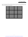
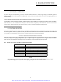
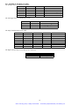
1
Artisan Technology Group is your source for quality
new and certified-used/pre-owned equipment
• FAST SHIPPING AND
DELIVERY
• TENS OF THOUSANDS OF
IN-STOCK ITEMS
• EQUIPMENT DEMOS
• HUNDREDS OF
MANUFACTURERS
SUPPORTED
• LEASING/MONTHLY
RENTALS
• ITAR CERTIFIED
SECURE ASSET SOLUTIONS
SERVICE CENTER REPAIRS
Experienced engineers and technicians on staff
at our full-service, in-house repair center
WE BUY USED EQUIPMENT
Sell your excess, underutilized, and idle used equipment
We also offer credit for buy-backs and trade-ins
www.artisantg.com/WeBuyEquipment
InstraView REMOTE INSPECTION
LOOKING FOR MORE INFORMATION?
Visit us on the web at www.artisantg.com for more
information on price quotations, drivers, technical
specifications, manuals, and documentation
SM
Remotely inspect equipment before purchasing with
our interactive website at www.instraview.com
Contact us: (888) 88-SOURCE | [email protected] | www.artisantg.com
PCM-DAS16D/12AO
ComputerBoards, Inc.
Revision 2
March 1999
Artisan Technology Group - Quality Instrumentation ... Guaranteed | (888) 88-SOURCE | www.artisantg.com
LIFETIME PRODUCT WARRANTY
Every ComputerBoards, Inc. product is warranted against defects in materials or workmanship for the life of the product, to the original
purchaser. Any products found to be defective in material or workmanship will be repaired or replaced promptly.
LIFETIME HARSH ENVIRONMENT WARRANTYTM
Any ComputerBoards, Inc. product which is damaged due to misuse may be replaced for only 50% of the current price. I/O boards face some
harsh environments, some harsher that the boards are designed to withstand. When that happens, just return the board with an order for its
replacement at only 50% of the list price. ComputerBoards does not need to profit from your misfortune. By the way, we will honor this warranty
for any other manufacture’s board that we have a replacement for!
30 DAY MONEY-BACK GUARANTEE
Any ComputerBoards, Inc. product may be returned within 30 days of purchase for a full refund of the price paid for the product being returned.
If you are not satisfied, or chose the wrong product by mistake, you do not have to keep it. Please call for a RMA number first. No credits or
returns accepted without a copy of the original invoice. Some software products are subject to a repackaging fee.
These warranties are in lieu of all other warranties, expressed or implied, including any implied warranty of merchantability or fitness for a particular
application. The remedies provided herein are the buyer’s sole and exclusive remedies.
Neither ComputerBoards, Inc., nor its employees shall be liable for any direct or indirect, special, incidental or consequential damage arising from the use of its
products, even if ComputerBoards has been notified in advance of the possibility of such damages.
Notice
ComputerBoards, Inc. does not authorize any ComputerBoards, Inc. product for use in life support systems
and/or devices without the written approval of the President of ComputerBoards, Inc. Life support
devices/systems are devices or systems which, a) are intended for surgical implantation into the body, or b)
support or sustain life and whose failure to perform can be reasonably expected to result in injury.
ComputerBoards, Inc. products are not designed with the components required, and are not subject to the
testing required to ensure a level of reliability suitable for the treatment and diagnosis of people.
(C) Copyright 1999 ComputerBoards, Inc.
No part of this manual may be reproduced without written permission from ComputerBoards, Inc.
Artisan Technology Group - Quality Instrumentation ... Guaranteed | (888) 88-SOURCE | www.artisantg.com
TABLE OF CONTENTS
1 INTRODUCTION
.............................................................. 1
2 WINDOWS 95, 98 INSTALLATION
..............................................
2.1 INSTALL THE InstaCal SOFTWARE PACKAGE . . . . . . . . . . . . . . . . . . . . . . . . . . . . . . . . . . . .
2.2 INSTALL THE PCMCIA CARD . . . . . . . . . . . . . . . . . . . . . . . . . . . . . . . . . . . . . . . . . . . . . . . . .
2.3 RUN InstaCal . . . . . . . . . . . . . . . . . . . . . . . . . . . . . . . . . . . . . . . . . . . . . . . . . . . . . . . . . . . . . . . . .
2.4 TESTING THE INSTALLATION . . . . . . . . . . . . . . . . . . . . . . . . . . . . . . . . . . . . . . . . . . . . . . . . .
2
2
2
3
3
3 WINDOWS 3.X OR DOS INSTALLATION
.........................................
3.1 INSTALL THE InstaCal SOFTWARE PACKAGE . . . . . . . . . . . . . . . . . . . . . . . . . . . . . . . . . . . .
3.2 INSTALL THE PCMCIA CARD . . . . . . . . . . . . . . . . . . . . . . . . . . . . . . . . . . . . . . . . . . . . . . . . .
3.3 RUN InstaCal . . . . . . . . . . . . . . . . . . . . . . . . . . . . . . . . . . . . . . . . . . . . . . . . . . . . . . . . . . . . . . . . .
3.4 TESTING THE INSTALLATION . . . . . . . . . . . . . . . . . . . . . . . . . . . . . . . . . . . . . . . . . . . . . . . . .
3.5 ABOUT DOS CARD & SOCKET SERVICES . . . . . . . . . . . . . . . . . . . . . . . . . . . . . . . . . . . . . . .
4
4
4
5
5
5
4 OPERATING MODES
..........................................................
4.1 ANALOG INPUT RESOLUTION & RANGE . . . . . . . . . . . . . . . . . . . . . . . . . . . . . . . . . . . . . . . .
4.2 CONVERSION SPEED & AMPLIFICATION . . . . . . . . . . . . . . . . . . . . . . . . . . . . . . . . . . . . . . .
4.3 TRIGGERING & TRANSFER . . . . . . . . . . . . . . . . . . . . . . . . . . . . . . . . . . . . . . . . . . . . . . . . . . . .
4.4 A/D PACER CONTROL . . . . . . . . . . . . . . . . . . . . . . . . . . . . . . . . . . . . . . . . . . . . . . . . . . . . . . . .
7
7
7
7
8
5 SOFTWARE
.................................................................. 9
5.1 PROGRAMMING LANGUAGES . . . . . . . . . . . . . . . . . . . . . . . . . . . . . . . . . . . . . . . . . . . . . . . . . 9
5.2 PACKAGED APPLICATIONS PROGRAMS . . . . . . . . . . . . . . . . . . . . . . . . . . . . . . . . . . . . . . . . 9
6 ANALOG CONNECTIONS
. . . . . . . . . . . . . . . . . . . . . . . . . . . . . . . . . . . . . . . . . . . . . . . . . . . . . 10
6.1 ANALOG INPUTS . . . . . . . . . . . . . . . . . . . . . . . . . . . . . . . . . . . . . . . . . . . . . . . . . . . . . . . . . . . . 10
6.2 ANALOG OUTPUTS . . . . . . . . . . . . . . . . . . . . . . . . . . . . . . . . . . . . . . . . . . . . . . . . . . . . . . . . . . 15
7 I/O CONNECTOR PINOUT
. . . . . . . . . . . . . . . . . . . . . . . . . . . . . . . . . . . . . . . . . . . . . . . . . . . . 16
8 BOARD ARCHITECTURE
. . . . . . . . . . . . . . . . . . . . . . . . . . . . . . . . . . . . . . . . . . . . . . . . . . . . . 17
8.1 SOFTWARE CALIBRATION . . . . . . . . . . . . . . . . . . . . . . . . . . . . . . . . . . . . . . . . . . . . . . . . . . 17
8.2 CONTROL REGISTERS . . . . . . . . . . . . . . . . . . . . . . . . . . . . . . . . . . . . . . . . . . . . . . . . . . . . . . . 17
APPENDIX A: SPECIFICATIONS
. . . . . . . . . . . . . . . . . . . . . . . . . . . . . . . . . . . . . . . . . . . . . . . . . 19
APPENDIX B: ELECTRONICS AND INTERFACING
. . . . . . . . . . . . . . . . . . . . . . . . . . . . . . . . . 21
B.1 VOLTAGE DIVIDERS . . . . . . . . . . . . . . . . . . . . . . . . . . . . . . . . . . . . . . . . . . . . . . . . . . . . . . . . 21
B.2 LOW PASS FILTERS . . . . . . . . . . . . . . . . . . . . . . . . . . . . . . . . . . . . . . . . . . . . . . . . . . . . . . . . 22
Artisan Technology Group - Quality Instrumentation ... Guaranteed | (888) 88-SOURCE | www.artisantg.com
1 INTRODUCTION
The Computer Boards PCM-DAS16D/12AO is a multifunction analog and digital I/O card for DOS and Windows compatible computers with PC Card (PCMCIA) type 2 or 3 slots. Based on our popular PCM-DAS16D series, this model adds two channels of
analog output. The heart of the board is an analog to digital converter. Analog signals are routed to the A/D via an 8:1 differential
multiplexer controlled by a register on the PCM-DAS16. The analog input range is fully software programmable to any of the
board’s eight ranges. An on board pacer clock, external pacer input or software polling may trigger A/D conversions. Transfers
may be via software polling, interrupt service or REP-INSW. A FIFO buffer provides data bus buffering between the A/D circuit
and the PCMCIA bus. Four digital I/O lines (set as 4 in or 4 out) provide a means of sensing and controlling discrete events.
1
Artisan Technology Group - Quality Instrumentation ... Guaranteed | (888) 88-SOURCE | www.artisantg.com
2 WINDOWS 95, 98 INSTALLATION
2.1 INSTALL THE InstaCal SOFTWARE PACKAGE
2.1.1 INTRODUCTION
InstaCal is the installation, calibration and test software supplied with your data acquisition / IO hardware. The complete InstaCal
package is also included with the Universal Library. If you have ordered the Universal Library, use the Universal Library disk set
to install InstaCal. The installation will create all required files and unpack the various pieces of compressed software. To install
InstaCal, simply run setup.exe, and follow the on-screen instructions.
2.1.2 INSTALLATION OPTIONS
If you are installing on a Windows 95 or 98 operating system, the "Installation Options" dialog box will allow you to install the 16
bit, the 32 bit or both versions of InstaCal. Select the 32 bit version unless you intend to use a 16 bit application or library to control your data acquisition hardware.
If you are installing from the Universal Library disk set, the "Installation Options" dialog box also presents options to install example programs for each language supported. Select the appropriate example programs for the language you will be using.
2.1.3 FILE DEFAULT LOCATION
InstaCal will place all appropriate files in "C:\CB." If you change this default location remember where the installed files are
placed as you may need to access them later.
2.1.4 INSTALLATION QUESTIONS
At the end of the installation process there will be a series of questions: unless you have knowledge to the contrary, simply accept
the default when prompted.
2.1.5 INSTALLATION COMPLETION
After the installation of InstaCal is complete you should restart your computer to take advantage of changes made to the system.
2.2 INSTALL THE PCMCIA CARD
Your PCM card is completely plug and play. There are no switches or jumpers to set prior to installation in your computer. Simply
follow the steps shown below to install your PCM - hardware.
1.
Insert the card into a free PC Card/PCMCIA type II or III slot. You do not have to turn the computer off. The system is
designed for power on installation. Shown here is a PCM card case looking into the connector which is inserted into the
PCMCIA slot of your computer. The KEY helps to insure that the PCM board is inserted in the correct orientation.
2.
If the appropriate drivers are already loaded on the PC, the card should be detected, recognized, and configured by Windows and you should hear an insertion beep. If the card is not detected by Windows, go to step 3. To verify the card has
been recognized, go to Control Panel\System\Device Manager and the card should now appear under "DAS Component."
If your card appears in the list you can now proceed to the "RUN InstaCal" section of this manual.
2
Artisan Technology Group - Quality Instrumentation ... Guaranteed | (888) 88-SOURCE | www.artisantg.com
3.
If the drivers are not already loaded on the PC, you will be prompted for a driver. If you are not prompted for a driver
after inserting the card, go to step 4. The appropriate driver is located on disk 1 of the installation disk set. Insert this
disk. Windows should detect the driver file automatically, install it and then the card should be detected by Windows and
you should hear an insertion beep. To verify the card has been recognized, go to Control Panel\System\Device Manager
and the card should now appear under "DAS Component." If your card appears in the list you can now proceed to the
"RUN InstaCal" section of this manual.
4.
If the card is not detected by Windows and you are not prompted for a driver after inserting the card, check that your computer's 32-bit PCMCIA drivers are enabled. If they are not, enable them and then restart your computer and try the above
procedure again.
2.3 RUN InstaCal
Run the InstaCal program in order to configure the board for run-time use. By configuring the board, you add information to the
configuration file, cb.cfg, that is used by the Universal Library and other third-party data acquisition packages that use the Universal Library to access the board.
2.3.1 RUNNING THE 32 BIT VERSION
You can run the 32 bit version of InstaCal by finding the file named "inscal32.exe" in your installation directory and double clicking it. You can also run InstaCal by going to your Start Menu then to Programs, then to ComputerBoards, and finally choosing
InstaCal.
If you have a PCM board inserted in a PCM slot in your computer, InstaCal displays a dialog box indicating the device has been
detected. Simply click "OK" to proceed with InstaCal.
If there are no other boards currently installed by InstaCal, then the PCM board will be assigned board number 0. Otherwise it will
be assigned the next available board number.
You can now view and change the board configuration by clicking the properties icon or selecting the Install\Configure menu.
2.3.2 RUNNING THE 16 BIT VERSION
You can run the 16 bit version of InstaCal by finding the file named "instacal.exe" in your installation directory and double clicking it. You can also run InstaCal by going to your Start Menu then to Programs, then to ComputerBoards, and finally choosing
"InstaCal 16."
If you have a PCM board inserted in a PCM slot in your computer, InstaCal displays a dialog box titled "Add PCM Card." Select
"Yes." The next dialog box allows you to select a board number. Choose the default (0 if no other cards are already installed) or
select a board number.
You can now select the Install menu (using the mouse or the letter "I" on the keyboard) to view or change the configuration of the
board.
2.4 TESTING THE INSTALLATION
After you have run the install program, it is time to test the installation. The following section describes the InstaCal procedure to
test that your board is properly installed.
With InstaCal running:
1.
Select the board you just installed.
2.
Select the "Test" function.
Follow the instructions provided to test for proper board operation.
3
Artisan Technology Group - Quality Instrumentation ... Guaranteed | (888) 88-SOURCE | www.artisantg.com
3 WINDOWS 3.X OR DOS INSTALLATION
3.1 INSTALL THE InstaCal SOFTWARE PACKAGE
InstaCal is the installation, calibration and test software supplied with your data acquisition / IO hardware. The complete InstaCal
package is also included with the Universal Library. If you have ordered the Universal Library, use the Universal Library disk set
to install Instacal. The installation will create all required files and unpack the various pieces of compressed software. To install
InstaCal, simply run setup.exe, and follow the on-screen instructions.
3.1.1 INSTALLATION OPTIONS
If you are installing from the Universal Library disk set, the "Installation Options" dialog box presents options to install libraries
and example programs for each language supported. Select the appropriate library version and example programs for the language
you will be using.
If your computer does not have the Windows operating system installed (only the DOS operating system is available), install the
separate DOS-only InstaCal package called "InstaCal for DOS, Universal Library for DOS" available from your vendor.
Computers running Windows 3.x and/or DOS need to use the DOS based Card & Socket Services (CSS) drivers. CSS is included
with most newer computers, but if you need to purchase these drivers, they are available from your vendor (order PCM CSS). During the InstaCal installation, you will be prompted to indicate whether or not to install CBCLIENT. Respond "Yes." CBCLIENT
is used by CSS to configure the PCMCIA data acquisition cards. Remember, if you do not have CSS loaded, install it before
attempting to use the PCMCIA card. More information about CSS is available in section 3.5 titled "About DOS Card & Socket
Services."
InstaCal will place all appropriate files in "C:\CB." If you change this default location remember where the installed files are
placed as you may need to access them later. At the end of the installation process there will be a series of questions: unless you
have knowledge to the contrary, simply accept the default when prompted.
After the installation of InstaCal is complete you should restart your computer to take advantage of changes made to the system.
3.2 INSTALL THE PCMCIA CARD
Insert the card into a free PCM card slot and wait for the insertion tone (a double beep).
Shown here is a PCM card case looking into the connector which is inserted into the PCMCIA slot of your computer. The KEY
helps to insure that the PCM board is inserted in the correct orientation.
4
Artisan Technology Group - Quality Instrumentation ... Guaranteed | (888) 88-SOURCE | www.artisantg.com
3.3 RUN InstaCal
Run the InstaCal program in order to configure the board for run-time use. By configuring the board, you add information to the
configuration file, cb.cfg, that is used by the Universal Library and other third-party data acquisition packages that use the Universal Library to access the board.
To run InstaCal in Windows 3.x, find the file named InstaCal.exe in your installation directory or simply double click the
InstaCal.exe icon.
From DOS, jsut type "Instacal" at the DOS prompt and hit "Enter."
If you have a PCM board inserted in a PCM slot in your computer, InstaCal displays a dialog box titled "Add PCM Card." Select
"Yes." The next dialog box allows you to select a board number. Choose the default (0 if no other cards are already installed) or
select a board number.
You can now select the install menu (using the mouse or the letter "I" on the keyboard) to view or change the configuration of the
board.
3.4 TESTING THE INSTALLATION
After you have run the install program and set your base address with InstaCal, it is time to test the installation. The following section describes the InstaCal procedure to test that your board is properly installed.
With InstaCal running, choose the TEST item on the main menu.
i.
Select the board you just installed
ii.
If the choice “Internal Test” is available, then select Internal Test. If not, proceed to "v." below.
iii. The internal control registers of the board will then be tested. If this test is successful, your board is installed correctly.
iv. If the Internal Test is completed successfully, you may want to check that the I/O pins are working correctly. To check this
select External Test and follow the instruction provided. This will require you to use the shorting wires supplied with the
board to connect inputs to outputs for I/O testing. Some external tests may require an external voltage source and ohmmeter. All required equipment and connections will be listed by InstaCal.
v.
If the “I/O Test Menu” lists the option “Plot”, the select it and make the connections as shown to test your card.
3.5 ABOUT DOS CARD & SOCKET SERVICES
The following section describes Card & Socket Services and should help you determine whether or not you need to install CSS.
Some operating systems, such as Windows 95, include an integrated version of CSS. If you are running such an operating system,
do not install DOS CSS unless you have a specific reason to do so.
Card and socket services for your PCM card are on a disk labeled "DOS Card & Socket Services." The software from that disk
should be installed if you do not already have CSS support on your PC.
3.5.1 WHAT IS CSS?
CSS is a program that communicates with your computers PCMCIA interface controller and configures it. The PCMCIA interface
is configurable, unlike the standard ISA bus you may be familiar with. If you plug a PCMCIA board into a PCMCIA slot and have
not yet run CSS, you will have no access to the functions of that PCMCIA board.
3.5.2 DOES CSS USE SYSTEM RESOURCES?
Yes. The CardSoft Card and Socket Services device drivers which are installed in your CONFIG.SYS use about 61K of memory.
These files can be installed DEVICEHIGH.
5
Artisan Technology Group - Quality Instrumentation ... Guaranteed | (888) 88-SOURCE | www.artisantg.com
The CBCLIENT.EXE installed in your AUTOEXEC.BAT uses about 10K of memory. The CBCLIENT.EXE program is a TSR
(Terminate and Stay Resident). You may modify the program line to LOADHIGH the TSR. We have tested it both high and low
with and without Windows and a variety of other applications. We believe it is a safe TSR that will not cause any system
problems.
3.5.3 HOW DO I KNOW CSS IS INSTALLED AND RUNNING?
There is a simple test. Just plug in your PCM-card. If CSS is installed and working the computer will beep. You can remove and
replace your PCM-card as often as you like and need not power down to do so. The computer should beep each time you insert the
PCM-card.
3.5.4 WHAT ABOUT CSS FOR MULTIPLE PCM BOARDS?
Once the current version of CSS is installed, CSS is installed for all PCM boards included in that version of CSS. As new PCM
boards become available, they will be added to the CSS and you will want to always have the most recent version of
CBCLIENT.EXE installed in the C:\CB directory. Let the installation software do this for you.
You can run multiple PCMCIA boards with the CBCLIENT.EXE CSS, and, if you have another CLIENT program running for
other PCMCIA boards, it will not interfere.
6
Artisan Technology Group - Quality Instrumentation ... Guaranteed | (888) 88-SOURCE | www.artisantg.com
4 OPERATING MODES
4.1 ANALOG INPUT RESOLUTION & RANGE
The 12 bit A/D converter provides a resolution of 1/4096 parts of full scale. The smallest reading of full scale (1 part in 4096) is
called a Least Significant Bit (LSB). Accuracy is specified in LSBs. The PCM-DAS16D/12AO is accurate to +/- 1 LSB. Eight
different ranges, four unipolar and four bipolar, are fully controlled by software. These are:
Unipolar
0 to 10V
0 to 5V
0 to 2.5V
0 to 1.25V
1LSB
0.00244V
0.00122V
0.0006V
0.0003V
Bipolar
+/-10V
+/-5V
+/-2.5V
+/-1.25V
1LSB
0.00488V
0.00244V
0.00122V
0.0006V
The input range is controlled by a programmable amplifier and is completely software selectable.
4.2 CONVERSION SPEED & AMPLIFICATION
The A/D chip always runs at full speed. The A/D converter and sample & hold circuit captures and digitizes a signal in 10 microseconds (10uS). The conversion speed of the A/D remains constant in all conditions and at all throughput rates. This is important.
When you request a sample rate of say 20KHz, the A/D converter is still converting the signal in 10uS. The 20KHz rate comes
from the fact that conversions are being initiated only every 50uS.
4.2.1 WHAT FACTORS LIMIT CONVERSION SPEED?
The first is clearly the A/D. A 10uS conversion speed translates to a maximum throughput of 100KHz. The second limiting factor
may be the analog front end.
The front-end consists of a multiplexer and a programmable gain amplifier. The speed at which these circuits can switch may also
limit the throughput of the A/D board. That is, the rate at which it can acquire, convert and transfer a signal with full accuracy.
Accuracy is the key term here. The A/D can always run at full speed, but has the front end settled and captured a true, accurate signal?
4.2.2 WHAT ABOUT INPUT RANGE VS. SPEED?
Here is where the design of the analog front end is critical to maintaining total throughput. The A/D chip has a fixed input range of
+/-10V. It is the analog front end that amplifies low level signals and adjusts unipolar signals to match the A/D converter's standard input.
A poorly designed analog front end will show up very quickly in the throughput specifications. If you see that an A/D board has
high throughput in only one or two ranges but is slowed greatly at all other ranges, you are seeing the practical implications of a
poor front end design. The PCM-DAS16D/12AO achieves 100KHz in all of the eight ranges.
4.3 TRIGGERING & TRANSFER
A Trigger is the event that begins an acquisition/transfer cycle. There are three ways to trigger a PCM-DAS16D/12AO; programmable pacer, software or external. The trigger source is programmable. The programmable pacer is the product of two 16 bit
counters dividing a 10MHz or 1MHz wave derived from a 10MHz XTAL which may be used to trigger any number of paced conversions. A single conversion may be triggered by software at any time. External trigger, pacer clock and interrupt signals may
also be used to control conversions and synchronize to external events.
Once a conversion is made the sample is placed into a 512 sample FIFO buffer from which it may be retrieved one sample at a time
or in blocks via REP-INSW transfers.
7
Artisan Technology Group - Quality Instrumentation ... Guaranteed | (888) 88-SOURCE | www.artisantg.com
4.3.1 HOW DO FIFO SIZE AND DESIGN AFFECT THROUGHPUT?
The FIFO buffer stores samples from the A/D converter as they are being converted. When a block of samples is ready and when
the PC is ready, the FIFO is emptied into system memory. A properly designed FIFO of the correct size is a requirement for Windows, or samples will be lost at all but the slowest speeds.
Design of the FIFO is critical. Simply having a FIFO is not enough. Most ComputerBoards FIFO designs employ a half-full transfer initiation circuit. When the FIFO is half full, the transfer request is made. Samples continue to fill the second half of the FIFO
while the CPU responds to the transfer request and transfers data to system memory.
Some other manufacturer's boards have only a 'FIFO full' circuit. What do you think happens to samples taken after the FIFO is
full while waiting for the CPU to begin unloading the FIFO? FIFO size is critical also. We have seen boards with FIFOs as small
as 16 samples. The PCM-DAS16D/12AO has a 512 sample FIFO buffer, a size we have determined through extensive testing to
be a requirement for real situations.
4.4 A/D PACER CONTROL
Many analog acquisitions can be handled by a simple on-board rate divider created by combining an XTAL with a programmable
counter. For those, the on-board 82C54 programmable rate generator supplies the pacing. Some applications require more flexible
rate control. The PCM-DAS16 analog conversions may be externally triggered and thereby synchronized with events external to
the PC. Conversions may be held off until some external event, such as a not-to-exceed condition is met. Conversions may be
externally gated so that samples are taken only when an event of interest is occurring, such as process over normal limits.
Shown here is the A/D pacer clock schematic and the routing of off board trigger signals.
In addition to the 8 analog inputs the PCM-DAS16D/12AO has an analog ground, 1 A/D trigger input, 1 interrupt input, 1 gate
input, complete access to one 16 bit counter's clock, gate and output lines, access to the A/D pacer's counter output line, and 4 digital output/inputs and four pins for the two analog outputs. A digital ground is in the cable shield clips to either side of the 33 pins
of the connector as well as one of the connector pins. Please look at the connector diagram for your board.
INPUT WARNING!
Do not exceed the input specifications. There are no socketed or user serviceable parts in a PCM board. Any
repair will be expensive. Analog inputs are limited to +/-15V, unlike the higher ratings of ISA boards. If you
apply a voltage < -0.5V or greater than 5.5V to a digital input, you will burn out the input transistor.
Please turn now to the table of specifications and familiarize yourself with them before connecting any signals.
8
Artisan Technology Group - Quality Instrumentation ... Guaranteed | (888) 88-SOURCE | www.artisantg.com
5 SOFTWARE
After running InstaCAL our PCM-DAS16D/12AO is installed and ready for use. Although the PCM-DAS16D/12AO is part of the
larger CIO-DAS16 family, there is no correspondence between registers. Software written at the register level for the CIO- DAS16
or PC104-DAS16's will not work with the PCM-DAS16D/12AO.
5.1 PROGRAMMING LANGUAGES
The ComputerBoards UniversalLibrary provides complete access to the PCM-DAS16D/12AO functions from a range of programming languages; both DOS and Windows. If you are planning to write programs, or would like to run the example programs for
Visual Basic or any other language, please turn now to the UniversalLibrary manual.
5.2 PACKAGED APPLICATIONS PROGRAMS
Many packaged application programs, such as Labtech Notebook now have drivers for the PCM-DAS16 family. If the package
you own does not appear to have drivers for the PCM-DAS16D/12AO please fax the package name and the revision number from
the install disks. We will research the package for you and advise by return fax how to obtain the correct drivers.
9
Artisan Technology Group - Quality Instrumentation ... Guaranteed | (888) 88-SOURCE | www.artisantg.com
6 ANALOG CONNECTIONS
6.1 ANALOG INPUTS
Analog signal connection is one of the most challenging aspects of applying a data acquisition board. If you are an Analog Electrical Engineer then this section is not for you, but if you are like most PC data acquisition users, the best way to connect your analog
inputs may not be obvious. Though complete coverage of this topic is well beyond the scope of this manual, the following section
provides some explanations and helpful hints regarding these analog input connections. This section is designed to help you
achieve the optimum performance from your PCM-DAS16D/12AO series board.
Prior to jumping into actual connection schemes, you should have at least a basic understanding of Single-Ended/Differential inputs
and system grounding/isolation. If you are already comfortable with these concepts you may wish to skip to the next section (on
wiring configurations).
6.1.1 DIFFERENTIAL INPUTS
Differential inputs measure the voltage between two distinct input signals. Within a certain range (referred to as the common mode
range), the measurement is almost independent of signal source to PCM-DAS16D/12AO ground variations. A differential input is
also much more immune to EMI than a single-ended one. Most EMI noise induced in one lead is also induced in the other, the
input only measures the difference between the two leads, and the EMI common to both is ignored. This effect is a major reason
there is twisted pair wire as the twisting assures that both wires are subject to virtually identical external influence. The diagram
below shows a typical differential input configuration.
CH H igh
+
Inp ut
Amp
CH L ow
To M U X
& A /D
-
LL GN D
I/O
C o nn ector
~
D ifferential Inpu t
C H H igh
Vs
C H L ow
Vcm
g1
+
Vs
Vcm = V g2 - Vg1
In p u t
Amp
To M U X
& A /D
-
LL G ND
g2
C om m on M ode Voltage (Vcm ) is ignored
by differential input configuration. H ow ever,
note that V cm + Vs m ust rem ain w ithin
the am plifier’s com m on m ode range of ±10V
D iffe re n tial In pu t w ith C om m on M o d e Vo lta ge
10
Artisan Technology Group - Quality Instrumentation ... Guaranteed | (888) 88-SOURCE | www.artisantg.com
Before moving on to the discussion of grounding and isolation, it is important to explain the concepts of common mode, and common mode range (CM Range). Common mode voltage is depicted in the diagram above as Vcm. Though differential inputs measure the voltage between two signals, without (almost) respect to the either signal’s voltages relative to ground, there is a limit to
how far away from ground either signal can go. Though the PCM-DAS16D/12AO has differential inputs, it will not measure the
difference between 100V and 101V as 1 Volt (in fact the 100V would destroy the board!). This limitation or common mode range
is depicted graphically in the diagram below. The PCM-DAS16D/12AO common mode range is +/- 10 Volts. Even in differential
mode, no input signal can be measured if it is more than 10V from the board’s low level ground (LLGND).
6.1.2 SYSTEM GROUNDS AND ISOLATION
There are three scenarios possible when connecting your signal source to your PCM-DAS16D/12AO board.
1.
The PCM-DAS16D/12AO and the signal source may have the same (or common) ground. This signal source may be connected directly to the PCM-DAS16D/12AO.
2.
The PCM-DAS16D/12AO and the signal source may have an offset voltage between their grounds (AC and/or DC). This
offset is commonly referred to as common mode voltage. Depending on the magnitude of this voltage, it may or may not
be possible to connect the PCM-DAS16D/12AO directly to your signal source. We will discuss this topic further in a later
section.
3.
The PCM-DAS16D/12AO and the signal source may already have isolated grounds. This may be the case due to the signals source being isolated from ground, or because the host computer of the PCM-DAS16 board is isolated from ground
(or both). In this case the signal source may be connected directly to the PCM-DAS16D/12AO.
6.1.3 WHICH SYSTEM DO YOU HAVE?
Try the following experiment. Using a battery powered voltmeter*, measure the voltage (difference) between the ground signal at
your signal source and at your PC. Place one voltmeter probe on the PC ground and the other on the signal source ground. Measure
both the AC and DC Voltages.
*If you do not have access to a voltmeter, skip the experiment and take a look a the following three sections. You may be able to
identify your system type from the descriptions provided.
If both AC and DC readings are 0.00 volts, you may have a system with common grounds. However, since voltmeters will average
out high frequency signals, there is no guarantee. Please refer to the section below titled Common Grounds.
If you measure reasonably stable AC and DC voltages, your system has an offset voltage between the grounds category. This offset
is referred to as a Common Mode Voltage. Please be careful to read the following warning and then proceed to the section describing Common Mode systems.
WARNING
If either the AC or DC voltage is greater than 10 volts, do not connect the PCM-DAS16D/12AO to this signal
source. You are beyond the boards usable common mode range and will need to either adjust your grounding
system or add special Isolation signal conditioning to take useful measurements. A ground offset voltage of
more than 15 volts will likely damage the PCM-DAS16D/12AO board and possibly your computer.
This is such an important point, that we will state it again. If the voltage between the ground of your signal
source and your PC is greater than 10 volts, your board will not take useful measurements. If this voltage is
greater than 15 volts, it will likely cause damage, and may represent a serious shock hazard! In this case you
will need to either reconfigure your system to reduce the ground differentials, or purchase and install special
electrical isolation signal conditioning.
If you cannot obtain a reasonably stable DC voltage measurement between the grounds, or the voltage drifts around considerably,
the two grounds are most likely isolated. The easiest way to check for isolation is to change your voltmeter to it’s ohm scale and
measure the resistance between the two grounds. It is recommended that you turn both systems off prior to taking this resistance
measurement. If the measured resistance is more than 100 Kohm, it’s a fairly safe bet that your system has electrically isolated
grounds.
11
Artisan Technology Group - Quality Instrumentation ... Guaranteed | (888) 88-SOURCE | www.artisantg.com
6.1.4 SYSTEMS WITH COMMON GROUNDS
In the simplest (but perhaps least likely) case, your signal source will have the same ground as the PCM-DAS16D/12AO. This
would typically occur when providing power or excitation to your signal source directly from the PCM-DAS16D/12AO. There may
be other common ground configurations, but it is important to note that any voltage between the PCM-DAS16D/12AO ground and
your signal ground is a potential error voltage if you set up your system based on a common ground assumption.
As a safe rule of thumb, if your signal source or sensor is not connected directly to an LLGND pin on your PCM-DAS16D/12AO,
it’s best to assume that you do not have a common ground even if your voltmeter measured 0.0 Volts. Configure your system as if
there is ground offset voltage between the source and the PCM-DAS16D/12AO. This is especially true if you are using the PCMDAS16D/12AO at high gains, since ground potentials in the sub millivolt range will be large enough to cause A/D errors, yet will
not likely be measured by your hand held voltmeter.
6.1.5 SYSTEMS WITH COMMON MODE (GROUND OFFSET) VOLTAGES
The most frequently encountered grounding scenario involves grounds that are somehow connected, but have AC and/or DC offset
voltages between the PCM-DAS16D/12AO and signal source grounds. This offset voltage my be AC, DC or both and may be
caused by a wide array of phenomena including EMI pickup, resistive voltage drops in ground wiring and connections, etc.
6.1.6 SMALL COMMON MODE VOLTAGES
If the voltage between the signal source ground and PCM-DAS16D/12AO ground is small, the combination of the ground voltage
and input signal will not exceed the PCM-DAS16D/12AO’s +/-10V common mode range. (i.e. the voltage between grounds, added
to the maximum input voltage, stays within +/-10V), This input is compatible with the PCM-DAS16D/12AO and the system may
be connected without additional signal conditioning. Fortunately, most systems will fall in this category and have a small voltage
differential between grounds.
6.1.7 LARGE COMMON MODE VOLTAGES
If the ground differential is large enough, the PCM-DAS16D/12AO’s +/- 10V common mode range will be exceeded (i.e. the voltage between PCM-DAS16D/12AO and signal source grounds, added to the maximum input voltage you’re trying to measure
exceeds +/-10V). In this case the PCM-DAS16D/12AO cannot be directly connected to the signal source. You will need to change
your system grounding configuration or add isolation signal conditioning. (Please give our technical support group a call to discuss
other options.)
NOTE
Relying on the earth prong of a 120VAC for signal ground connections is not advised.. Different ground plugs
may have large and potentially even dangerous voltage differentials. Remember that the ground pins on 120VAC
outlets on different sides of the room may only be connected in the basement. This leaves the possibility that the
“ground” pins may have a significant voltage differential (especially if the two 120 VAC outlets happen to be on
different phases!)
6.1.8 PCM-DAS16D/12AO AND SIGNAL SOURCE ALREADY HAVE ISOLATED GROUNDS
Some signal sources will already be electrically isolated from the PCM-DAS16D/12AO. The diagram below shows a typical isolated ground system. This is often the case with PCM-based systems as they are frequently battery powered and not tied to any
local ground. In addition, the signal source may be battery powered, or fully isolated. Isolated ground systems provide excellent
performance, but require some extra effort during connections to assure optimum performance is obtained. Please refer to the following sections for further details.
12
Artisan Technology Group - Quality Instrumentation ... Guaranteed | (888) 88-SOURCE | www.artisantg.com
6.1.9 WIRING CONFIGURATIONS
Combining all the grounding and input type possibilities provides us with the following potential connection configurations. The
combinations along with our recommendations on usage are shown in the chart below.
The following sections depicts recommended input wiring schemes for each of the possible input configuration/grounding combinations.
6.1.10 COMMON GROUND/DIFFERENTIAL INPUTS
The use of differential inputs to monitor a signal source with a common ground is an acceptable configuration though it requires
more wiring and offers fewer channels than selecting a single-ended configuration. The diagram below shows the recommended
connections in this configuration.
l
S ig n a rc e w it h
d
S ou
on G n
Comm
C H H igh
+
C H L ow
In p ut
Amp
To M U X
& A /D
-
LL G N D
O p tio nal w ire
since signa l sou rce
and A /D bo ard sha re
com m o n g round
I/O
C o n n ec tor
A /D B o ard
R equ ired connection
of L L G N D to C H Low
S ignal source an d A /D board
sharing com m o n ground conn ected
to d iffe rential input.
6.1.11 COMMON MODE VOLTAGE < +/-10V/DIFFERENTIAL INPUTS
Systems with varying ground potentials should always be monitored in the differential mode. Care is required to assure that the sum
of the input signal and the ground differential (referred to as the common mode voltage) does not exceed the common mode range
of the A/D board (+/-10V on the PCM-DAS16D/12AO). The diagram below show recommended connections in this configuration.
S ig n a
e
l S o u rc o m m o n
w it h C d e V o lt a g e
Mo
GND
C H H igh
C H L ow
+
In p ut
Amp
To M U X
& A /D
-
LL G N D
T he v olta ge d iffe ren tia l
b e tw ee n th e se gro un ds ,
a d de d to th e m a xim u m
in p ut sig n a l m ust sta y
w ithin + /-10V
I/O
C o n n ec tor
A /D B o ard
S ignal source an d A /D b oard
w ith com m on m ode vo ltag e
connecte d to a differen tial input.
13
Artisan Technology Group - Quality Instrumentation ... Guaranteed | (888) 88-SOURCE | www.artisantg.com
6.1.12 COMMON MODE VOLTAGE > +/-10V
The PCM-DAS16D/12AO will not directly monitor signals with common mode voltages greater than +/-10V. You will either need
to alter the system ground configuration to reduce the overall common mode voltage, or add isolated signal conditioning between
the source and your board.
Iso latio n
B arrie r
co m m
on
L a rg e d e v o lt a g e ig n a l
mo
een s
b o a rd
b e tw rc e & A /D
so u
GND
CH H igh
+
Inp ut
Amp
C H L ow
To M U X
& A /D
-
10 K
LL GN D
I/O
C o nn ector
W h en the voltage difference
between sig nal source a nd
A /D boa rd g ro und is large
eno ugh so the A /D board’s
com m on mod e range is
exceeded, isolate d sig nal
conditioning m ust be added.
A /D B oa rd
1 0K is a reco m m e nded va lu e. You m ay sh ort LL G N D to C H Low
in ste ad , but this w ill redu ce yo ur system ’s n oise im m unity.
System w ith a Large C om m on M ode Voltage,
C onnected to a D ifferential Input
6.1.13 ISOLATED GROUNDS/DIFFERENTIAL INPUTS
Optimum performance with isolated signal sources is assured with the use of the differential input setting. The diagram below
shows the recommend connections is this configuration.
e
l S o u rc
a rd
S ig n a n d A /D B o o la te d .
a
y Is
A lr e a d
GND
C H H igh
C H L ow
+
In p ut
Amp
To M U X
& A /D
-
10 K
LL G N D
I/O
C o n n ec tor
T he se g ro u n ds are
e le ctrica lly isolate d .
A /D B o ard
1 0 K is a rec o m m e nd ed v a lue . You m a y s ho rt LL G N D to C H L o w
in s te ad , b u t th is w ill re du c e yo ur s y s te m ’s n o ise im m u nity.
A lready isolated signal source
and A /D b oard connected to
a differe ntia l input.
14
Artisan Technology Group - Quality Instrumentation ... Guaranteed | (888) 88-SOURCE | www.artisantg.com
6.2 ANALOG OUTPUTS
Analog outputs are simple voltage outputs which can be connected to any device which will record, display or be controlled by a
voltage. The PCM-DAS16D/12AO analog outputs can be set to ±5V or ±10V full scale.
The output ranges of the PCM-DAS16D/12AO are set by software. The output ranges may be set within your program and range
selection is supported by the Universal Library.
6.2.1 CONNECTING DEVICES TO THE ANALOG OUTPUTS
The PCM-DAS16D/12AO analog outputs are single ended. There is an analog ground for each analog output channel. When connecting to the analog output channels you should be sure that LL Gnd on pins 13 and/or 15 are used for Vout return connections.
You should be careful to avoid ground potentials between your external system and your computer board. In addition to avoiding
potentials between signal grounds, you must also avoid potentials between signal ground and chassis ground on your computer. If
you are using a laptop and are on battery power, the computer is floating with respect to earth ground, but if the laptop is on the
charger unit or on wall power, the laptop may be grounded.
Whenever the computer is grounded, you must connect signals so there is no potential between PC ground and signal ground. If
there is a potential, it will be added to the signal. For example, if your PCM-DAS16D/12AO is supplying 3.5 volts and there is a
potential of -1.5V between the PC and the sensor ground, your device under control will be reading 2.0V instead of 3.5V
6.2.2 OUTPUT VOLTAGE RANGES
There are two possible output voltage ranges. Each DAC may be controlled independently, meaning that each DAC may have a
different range. The output voltage range is controlled by software and may be selected via the Universal Library. To learn about
controlling the outputs of the DACs please consult your software manual, either UniversalLibrary for programmers, or your application user's manual.
The available ranges are:
Range
+/-5V
+/-10V
LSB Step Size
0.00244 V
0.00488 V
15
Artisan Technology Group - Quality Instrumentation ... Guaranteed | (888) 88-SOURCE | www.artisantg.com
7 I/O Connector Pinout
The I/O connections are made through a 33-pin miniature connector. We recommend you connect your field wiring to our CIOMINI37 or CIO-TERMINAL screw terminal accessory board which then connects to the PCM card via the PCM-C37/33 cable.
The Pinout of the PCM-DAS16D/12AO is shown below.
PIN#
1
2
3
4
5
DESIGNATION
CTR 1 out
CTR 1 gate
CTR 1 CLK
CTR 3 out
Ext Trig/Clk
PIN#
18
19
20
21
22
DESIGNATION
CHO Lo IN
CHO Hi IN
CH1 Lo IN
CH1 Hi IN
CH2 Lo IN
6
7
8
9
10
CTR 2 Gate
Ext INT
Dig Gnd
DIO 0
DIO 1
23
24
25
26
27
CH2 Hi IN
CH3 Lo IN
CH3 Hi IN
CH4 Lo IN
CH4 Hi IN
11
12
13
14
15
DIO 2
DIO 3
LL Gnd
Vout 0
LL Gnd
28
29
30
31
32
CH5 Lo IN
CH5 Hi IN
CH6 Lo IN
CH6 Hi IN
CH7 Lo IN
16
17
Vout 1
LL Gnd
33
CH7 Hi IN
16
Artisan Technology Group - Quality Instrumentation ... Guaranteed | (888) 88-SOURCE | www.artisantg.com
8 BOARD ARCHITECTURE
8.1 SOFTWARE CALIBRATION
If you are using the UniversalLibrary, you can set software calibration factors for offset and gain using the Calibration option of
InstaCal. These factors will be applied to readings made by any of the A/D routines called from any of the language libraries of
UniversalLibrary.
Choose Calibration from the InstaCal menu, and follow the instructions. Press F1 for help.
A base address register controls the beginning, or 'Base Address' of the I/O addresses occupied by the control registers of the PCMDAS16D/12AO. In all, 32 addresses are occupied. The base address assigned by Card and Socket Services is stored in the
CB.CFG file by Instacal and read by the Universal Library. Please read about installing and using InstaCal.
8.2 CONTROL REGISTERS
Once CSS is installed and a base address has been established, the PCM-DAS16 may be controlled by writing to and reading from
the control registers. While it is possible to write your own control routines for the PCM-DAS16, routines have been written and
are available in ComputerBoards' Universal Library for DOS and Windows programming languages.
NOTE ON REGISTER PROGRAMMING SUPPORT
While the complete register map is explained here, only very limited support for assembly language or direct register programming
is available. Register level programming should only be attempted by experieced programmers. We support the use of the PCMDAS16D/12AO through high level languages using UniversalLibrary and the expample programs provided.
8.2.1 MAJOR FUNCTIONS OF THE CONTROL REGISTERS
I/O ADDRESS
BASE + 0
BASE + 2
BASE + 4
BASE + 6
BASE + 8
BASE + A
BASE + C
BASE + E
PCM-DAS16D/12AO FUNCTION R | W
A/D Data & Channel | Start A/D
Digital I/O, Channel Scan Limits
Interrupt Control & Status, D/A Control
Input Range and Trigger Method
Counter 0 Read | Load
Counter 1 Read | Load
Counter 2 Read | Load
None | Counter Control
NOTE
Since digital output control shares the same register as channel scan limits, simultaneous operation of digital
output and analog input is not possible when acquiring analog data on more than one channel.
17
Artisan Technology Group - Quality Instrumentation ... Guaranteed | (888) 88-SOURCE | www.artisantg.com
8.2.2 INTERRUPT SOURCE CONTROL
The interrupt source is controlled by three bits.
INT2
INT1
0
0
0
1
0
1
1
0
1
0
INT0
1
0
1
0
1
SOURCE
Pacer - Counter 2
External - Pin 7
FIFO Not Empty
FIFO Half Full
End of Channel Scan
The A/D trigger source is controlled by two bits.
TS1
0
1
1
TS0
X
0
1
SOURCE
Software Trigger
Rising Trigger Input, Pin 5
Pacer - Counter 2
The range of analog input is set by 4 bits.
G3
1
0
0
0
0
0
0
0
G2
0
0
0
0
1
1
1
1
G1
0
0
0
1
0
0
1
1
G0
0
0
1
0
0
1
0
1
RANGE
+/- 10 V
+/- 5 V (A/D Std.)
+/- 2.5 V
+/- 1.25 V
0 to 10 V
0 to 5 V
0 to 2.5 V
0 to 1.25 V
The digital I/O lines may be set as follows via 1 control bit.
LDIR
0
1
Bits 3:0
Input
Output
18
Artisan Technology Group - Quality Instrumentation ... Guaranteed | (888) 88-SOURCE | www.artisantg.com
Appendix A: SPECIFICATIONS
Typical for 25°C unless otherwise specified.
ANALOG INPUT SECTION
A/D convertor type
Resolution
Programmable ranges
A/D pacing
A/D Trigger sources
Data transfer
Polarity
Number of channels
ADS7804
12 bits
±10V,±5V,±2.5V,±1.25V,0-10V,0-5V,0-2.5V,0-1.25V
Programmable: internal counter or external source (Ext Trig)
External hardware/software (Ext Trig)
From 512 sample FIFO via REPINSW, interrupt or software polled
Bipolar, Unipolar
8 Differential
A/D conversion time
Throughput (post-process calibration)
Accuracy (software calibrated)
Integral Linearity
Channel crosstalk
Gain drift
Zero drift
Common Mode Range
CMRR @ 60Hz
Input leakage current
Input impedance
Absolute maximum input voltage
ANALOG OUTPUT SECTION
D/A convertor type
Resolution
Number of channels
Ranges
10µs
100ksamples/sec
±1 LSB
±1 LSB
±1 LSB
160ppm/°C
150ppm/°C
±10V
-72dB
200nA
10Mohms
±15V
LTC1446
12 bits
2 Voltage Output Single-ended
±10V, ±5V, each channel independently programmable
Offset error
Gain error
±1 LSB
±1 LSB
Differential nonlinearity
Integral nonlinearity
Monotonicity
D/A Gain drift
D/A offset drift
±0.5 LSB max
±5 LSB max, ±2 LSB typ
Guaranteed monotonic over temperature
±0.1 LSB / °C
±15µV / °C
D/A pacing
Data transfer
Throughput (post-process calibration)
Slew Rate
Current Drive
Output short-circuit duration
Output coupling
Output impedance
Software
Software
System dependent
0.5 V/µs
±2 mA
Indefinite @12mA
DC
200 ohms open loop
Miscellaneous
Double buffered output latches
Channel crosstalk
±1 LSB max
Output inverted (0 code = +FS, 4095 = -FS)
Noise
< 3 LSBs
19
Artisan Technology Group - Quality Instrumentation ... Guaranteed | (888) 88-SOURCE | www.artisantg.com
COUNTER SECTION
Counter type
82C54
Configuration
3 down counters, 16 bits each
Counter 0
Source: Programmable external (Ctr0 Clk) or 100kHz internal source
Gate: Available at connector (Ctr0 Gate)
Output: Available at connector (Ctr0 Out)
Counter 1 - ADC Pacer Lower Divider
Source: Programmable, 1MHz or 10 MHz internal source
Gate: Available at connector (Ctr1 Gate), pulled to logic high through 10k resistor
Output: Chained to Counter 2 Clock
Counter 2 - ADC Pacer Upper Divider
Source: Counter 1 Output
Gate: Available at connector (Ext Trig). Programmable enable / disable
Output: ADC Pacer clock, available at user connector (Ctr2 Out)
Clock input frequency
High pulse width (clock input)
Low pulse width (clock input)
Gate width high
Gate width low
Input low voltage
Input high voltage
Output low voltage
Output high voltage
DIGITAL I/O SECTION
Digital type
Configuration
10Mhz max
30ns min
50ns min
50ns min
50ns min
0.8V max
2.0V min
0.4V max
3.0V min
Input low voltage
Input high voltage
Output low voltage
Output high voltage
Absolute maximum input voltage
Interrupts
Interrupt enable
Interrupt sources
FPGA
One port, four bits
Programmable as 4 input, or 4 output
0.8V max
2.0V min
(IOL = 4mA)
0.23V max
(IOH = -4mA) 3.86V min
-0.5V , +5.5V
Programmable: levels 2 - 15
Programmable
End-of-conversion, FIFO-half-full, external (Ext Int, pin 7)
+5V quiescent
+5V during CIS read
75 mA typical, 105 mA max
90 mA typical, 130 mA max
ENVIRONMENTAL
Operating temerature range
Storage temerature range
Humidity
0 to 60°C
-40 to 100°C
0 to 90% non-condensing
20
Artisan Technology Group - Quality Instrumentation ... Guaranteed | (888) 88-SOURCE | www.artisantg.com
Appendix B: ELECTRONICS AND INTERFACING
B.1 VOLTAGE DIVIDERS
If you wish to measure a signal which varies over a range greater than the input range of a digital input, a voltage divider can drop
the voltage of the input signal to the level the digital input can measure.
A voltage divider takes advantage of Ohm's law, which states,
Voltage = Current * Resistance (commonly V=IR)
and Kirkoff's voltage law which states,
The sum of the voltage drops around a circuit will be equal to the voltage drop for the entire circuit.
Implied in the above is that any variation in the voltage drop for the circuit as a whole will have a proportional variation in all the
voltage drops in the circuit.
A voltage divider takes advantage of the fact that the voltage across one of the resistors in a circuit is proportional to the voltage
across the total resistance in the circuit.
SIGNAL
HIGH
SIGNAL
VOLTS
R1
V1
A/D BOARD
HIGH INPUT
Vin
V2
Vout
R2
A/D BOARD
LOW INPUT
SIGNAL
LOW
SIMPLE VOLTAGE DIVIDER -
Vin
Vout
=
R1+R2
R2
The trick to using a voltage divider is to choose two resistors with the proper proportions relative to the full scale of the digital
input and the maximum signal voltage.
The phenomena of dropping the voltage proportionally is often called attenuation. The formula for attenuation is:
Attenuation = R1 + R2
R2
2 = 10K + 10K
10K
R1 = (A - 1) * R2
The variable Attenuation is the proportional difference between the signal voltage max and the full
scale of the analog input.
For example, if the signal varies between 0 and 20
volts and you wish to measure that with an analog
input with a full scale range of 0 to 10 volts, the
Attenuation is 2:1 or just 2.
For a given attenuation, pick a handy resistor and
call it R2, then use this formula to calculate R1.
21
Artisan Technology Group - Quality Instrumentation ... Guaranteed | (888) 88-SOURCE | www.artisantg.com
Digital inputs also make use of voltage dividers, for example, if you wish to measure a digital signal that is at 0 volts when off and
24 volts when on, you cannot connect that directly to the digital inputs. The voltage must be dropped to 5 volts max when on. The
Attenuation is 24:5 or 4.8. Use the equation above to find an appropriate R1 if R2 is 1K. Remember that a TTL input is 'on' when
the input voltage is greater than 2.5 volts.
IMPORTANT NOTE: The resistors, R1 and R2, are going to dissipate all the power in the divider circuit
according to the equation Current = Voltage / Resistance. The higher the value of the resistance (R1 + R2) the
less power dissipated by the divider circuit. Here is a simple rule:
For Attenuation of 5:1 or less, no resistor should be less than 10K.
For Attenuation of greater than 5:1, no resistor should be less than 1K.
The CIO-TERMINAL has the circuitry on board to create custom voltage dividers. The CIO-TERMINAL is a 16" by 4" screw terminal board with two 37 pin D type connectors and 56 screw terminals (12 - 22 AWG). Designed for table top, wall or rack
mounting, the board provides prototype, divider circuit, filter circuit and pull-up resistor positions which you may complete with
the proper value components for your application.
B.2 LOW PASS FILTERS
A low pass filter is placed on the signal wires between a signal and an A/D board. It stops frequencies greater than the cut off frequency from entering the A/D board's analog or digital inputs.
The key term in a low pass filter circuit is cut off frequency. The cut of frequency is that frequency above which no variation of
voltage with respect to time may enter the circuit. For example, if a low pass filter had a cut off frequency of 30 Hz, the kind of
interference associated with line voltage (60Hz) would be filtered out but a signal of 25Hz would be allowed to pass.
Also, in a digital circuit, a low pass filter might be used to de-bounce an input from a momentary contact button pushed by a
person.
SIGNAL HIGH
A/D Board
High Input
R
C
SIGNAL
VOLTS
A/D Board
Low Input
SIGNAL LOW
LOW PASS FILTER - F c =
1
2*Pi*R*C
A low pass filter may be constructed from one resistor (R) and one capacitor (C). The cut off frequency is determined according to
the formula:
Fc =
R =
1
2 * Pi * R * C
1
2 * Pi * C * Fc
Where Pi = 3.14
22
Artisan Technology Group - Quality Instrumentation ... Guaranteed | (888) 88-SOURCE | www.artisantg.com
EC Declaration of Conformity
We, ComputerBoards, Inc., declare under sole responsibility that the product:
PCM-DAS16D/12AO
Part Number
PC CARD Analog I/O interface card
Description
to which this declaration relates, meets the essential requirements, is in conformity with, and CE marking has been applied
according to the relevant EC Directives listed below using the relevant section of the following EC standards and other normative
documents:
EU EMC Directive 89/336/EEC: Essential requirements relating to electromagnetic compatibility.
EU 55022 Class B: Limits and methods of measurements of radio interference characteristics of information technology
equipment.
EN 50082-1: EC generic immunity requirements.
IEC 801-2: Electrostatic discharge requirements for industrial process measurement and control equipment.
IEC 801-3: Radiated electromagnetic field requirements for industrial process measurements and control equipment.
IEC 801-4: Electrically fast transients for industrial process measurement and control equipment.
Carl Haapaoja, Director of Quality Assurance
Artisan Technology Group - Quality Instrumentation ... Guaranteed | (888) 88-SOURCE | www.artisantg.com
ComputerBoards, Inc.
16 Commerce Boulevard
Middleboro, MA 02346
T:(508) 946-5100
F: (508)946-9500
www.computerboards.com
Artisan Technology Group - Quality Instrumentation ... Guaranteed | (888) 88-SOURCE | www.artisantg.com
Artisan Technology Group is your source for quality
new and certified-used/pre-owned equipment
• FAST SHIPPING AND
DELIVERY
• TENS OF THOUSANDS OF
IN-STOCK ITEMS
• EQUIPMENT DEMOS
• HUNDREDS OF
MANUFACTURERS
SUPPORTED
• LEASING/MONTHLY
RENTALS
• ITAR CERTIFIED
SECURE ASSET SOLUTIONS
SERVICE CENTER REPAIRS
Experienced engineers and technicians on staff
at our full-service, in-house repair center
WE BUY USED EQUIPMENT
Sell your excess, underutilized, and idle used equipment
We also offer credit for buy-backs and trade-ins
www.artisantg.com/WeBuyEquipment
InstraView REMOTE INSPECTION
LOOKING FOR MORE INFORMATION?
Visit us on the web at www.artisantg.com for more
information on price quotations, drivers, technical
specifications, manuals, and documentation
SM
Remotely inspect equipment before purchasing with
our interactive website at www.instraview.com
Contact us: (888) 88-SOURCE | [email protected] | www.artisantg.com