1
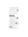
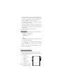
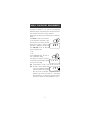
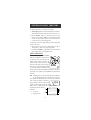
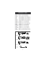
Instruction Manual
HI 98811
Fast Tracker
Thermometer
w w w. h a n n a i n s t . c o m
Dear Customer,
Thank you for choosing a Hanna Instruments Product.
Please read this instruction manual carefully before using the instrument.
This manual will provide you with all the necessary information for the
correct use of the instrument, as well as a precise idea of its versatility
in a wide range of applications.
If you need additional technical information, do not hesitate to e-mail
us at [email protected].
WARRANTY
HI 98811 is guaranteed for two years against defects in workmanship
and materials when used for its intended purpose and maintained
according to instructions. Probes are guaranteed for a period of six
months. This warranty is limited to repair or replacement free of charge.
Damage due to accidents, misuse, tampering or lack of prescribed
maintenance is not covered.
If service is required, contact the dealer from whom you purchased the
instruments. If under warranty, report the model number, date of
purchase, serial number and the nature of the problem. If the repair
is not covered by the warranty, you will be notified of the charges
incurred. If the instruments are to be returned to Hanna Instruments, first obtain a Returned Goods Authorization number from the
Technical Service department and then send it with shipping costs
prepaid. When shipping any instrument, make sure it is properly
packed for complete protection.
TABLE OF CONTENTS
WARRANTY ............................................................................................ 2
PRELIMINARY EXAMINATION ..................................................................... 3
GENERAL DESCRIPTION ........................................................................... 3
FUNCTIONAL DESCRIPTION ....................................................................... 5
SPECIFICATIONS .................................................................................. 6
INITIAL PREPARATION .............................................................................. 7
SETUP MODE
.................................................................................. 8
TAKING TEMPERATURE MEASUREMENTS ................................................ 14
PRINTING / LOGGING FUNCTIONS .......................................................... 15
GOOD LABORATORY PRACTICE (GLP) ..................................................... 19
OTHER FEATURES ............................................................................................ 19
DATA TRANSFER TO PC ......................................................................... 20
MEMORY ORGANIZATION ...................................................................... 21
PRINTER MAINTENANCE ....................................................................... 22
FAULT CONDITIONS .............................................................................. 22
BATTERY REPLACEMENT ....................................................................... 23
TEMPERATURE PROBES ....................................................................... 24
UN-HOUSED NTC SENSORS ................................................................... 25
ACCESSORIES ...................................................................................... 26
2
PRELIMINARY EXAMINATION
Remove the instrument from the packing material and examine it
carefully to make sure that no damage has occurred during shipping.
If there is any damage, notify your Dealer.
Each thermometer is supplied complete with:
• HI762BL Temperature Probe
• 1.5V AA Alkaline Batteries (4 pcs)
• Paper rolls (5 pcs)
• Tags with holders (5 pcs)
• Rugged Carrying Case
• Instruction Manual
Note: Save all packing material until you are sure that the
instrument functions correctly. All defective items must be
returned in their original packaging together with the supplied accessories.
GENERAL DESCRIPTION
The Hanna Instruments portable NTC Fast Tracker thermometer with
built-in printer enables you to accurately measure and record both
temperature and sample identification data.
The instrument housing is made of rugged and lightweight material
making it truly portable.
The meter comes equipped with an easy-to-read LCD with backlight
feature for comfortable reading even in dark environments.
A user friendly interface provides clear messages regarding errors,
functions and more.
The GLP features provide a guarantee of data consistency.
The Sample Identification feature eliminates the necessity of manual
identification for different measurement results, reducing the human errors.
Measurements can be performed with lab-grade precision, in the field as
well as in the laboratory.
An alarm time-out is available to alert the user if more than one year
has elapsed since the last calibration and that recalibration may be
required.
The meter provides GLP settings through a password protection method.
The Battery Error Preventing System (BEPS) recognizes batteries levels
as they become weaker to prevent erroneous readings.
3
To prolong battery life, the backlight and printing features are
disabled when the batteries are getting low; "LOBAT" indication is
displayed on LCD to warn the user of this condition. However, the
meter continues to measure correctly even when the low battery
indication is displayed. The meter automatically switches itself off
when the batteries are too weak to support proper function.
The meter is equipped with an internal lithium battery that powers
the clock circuit even in the absence of power supplies.
For long term field and lab applications, this meter can be connected to
a 12VDC adapter.
HI 98811 has the capability to store the measurements in memory at
a user selectable interval from 1 to 180 minutes. This information can
be retrieved at a later time and also printed.
Each measurement/lot can be uniquely identified by assigning a
sample ID code obtained by reading from a Dallas i-Button® tag
(DS1990A, etc) suitable placed in the field.
HI 98811 also allows the transfer of stored data to a computer via
the HI9200 infrared transmitter connected to the computer RS232
port.
Each meter can also be uniquely identified by the user by assigning
an instrument ID code.
i-Button® is registered Trademark of "Maxim/Dallas Semiconductor Corp."
4
FUNCTIONAL DESCRIPTION
1)
2)
3)
4)
5)
6)
7)
8)
9)
10)
11)
12)
13)
14)
15)
Power adapter plug
Temperature Probe Connector
Liquid Crystal Display (LCD)
PAPER key, to move the paper up
ON/OFF key, to turn the meter on or off
ALT key, to alternate key function
TEMP/TIME key, to select temperature reading, to view date
and time, and to enable backlight (with ALT)
LOG key, to store and/or print measurements
â LOT INFO key, to move down or view logging information
(with ALT)
à CFM key, to move right or confirm values (with ALT)
á FNC key, to move up or select function codes (with ALT)
Touch probe, to connect and read the i-Button tag
Printer
Battery location
RS232 - communication infrared leds
5
SPECIFICATIONS
Range
Resolution
Accuracy
(@20°C/68°F)
-50.0 to 150.0 °C ; -55.0 to 300.0 °F
0.1 °C (-30 °C to +130 °C); 0.2 °C outside
0.1 °F (-18 °F to 225 °F);
0.2 °F (225°F to 260 °F); 0.3 °F outside
±0.4 °C (-20 °C to +120°C); ±0.7 °C outside
±0.8 °F (-4 to +248 °F); ±1.3 °F outside
for one year (excluding probe error)
Typical EMC Dev.
Channels
Probe
Sample Identification tag
Printer
Printing/Logging
Interval
Serial interface
Auto shut-off
Power supply
Environment
Dimensions
Weight
±0.4 °C; ±0.8 °F
1 channel
HI 762 series
Dallas i-Button® family (DS 1990A, etc)
Low power impact type-belt, 14 characters
per line; 38 mm plain paper (HI 710034)
1, 2, 5,10, 15, 30, 60, 120 and 180 minutes
Infrared RS232, selectable at 1200, 2400, 4800,
9600 baud.
Selectable at 5, 10, 15, 30, 45 or 60 minutes
4x1.5V AA alkaline type/350 hours typical life (with
2700mA/h batteries, without printing and backlight).
12 VDC adapter (HI 710005 or HI 710006)
0 to 50°C (32 to 122°F);
0-95% RH non-condensing
220 x 82 x 66 mm (8.7 x 3.2 x 2.6")
500 g (18 oz)
i-Button® is registered Trademark of "Maxim/Dallas Semiconductor Corp."
6
INITIAL PREPARATION
Each meter is supplied complete with batteries. Remove the back
cover, unwrap the batteries and install them while paying attention to
the polarity. Alternatively, connect the HI 710005 or HI 710006
voltage adapter to the power adapter plug.
To prepare the instrument for use, choose the most appropriate temperature probe for your application (see accessories) and connect it to
the connector located on the top of the instrument.
All the probes have been factory precalibrated and no calibration is
needed.
To turn the meter on, press the ON/OFF key.
The batteries charge status or "LINE" message
(if external power adapter is connected) will be
displayed on the LCD for a few seconds.
FNC
The meter is now ready to operate.
To maximize battery life, the meter is automatically turned off after a
user selectable period of non-use (this feature is enabled and set to
5 minutes by default; it can be disabled or changed through setup
code 40). If in logging mode, after the period of non-use, the meter
will continue to monitor the temperature periodically at the end of
every logging interval. Only the "LOG" indication will be visible on
LCD. While storing data in memory, during the sleep mode, the
reading will appear briefly on the LCD.
To reactivate the display, press the ON/OFF key.
Note: When the use of an alternate function (FNC, CFM and LOT
INFO) is requested, press and hold the ALT key first and then
the second listed key.
7
SETUP MODE
Setup can be used to view data regarding the instrument status
(e.g. battery charge) or GLP data (e.g. calibration date) or to view
or print the logged data. It also allows the user to change the meter
parameters (e.g. time) and to gain access to stored data.
• To enter setup mode, ensure the meter is
not logging and then press the ALT and
FNC keys.
ALT
FNC
• The scrolling message <Insert the function code or press "ALT" "FNC" to escape> on the upper LCD and the indication "F 00"
with the number blinking on the lower LCD will be displayed.
• Choose the parameter code you want to set using the á or â
keys.
FNC
LOT INFO
• Press ALT and CFM to confirm the code.
ALT
CFM
8
PASSWORD PROTECTION
Setting the GLP parameters (calibration alarm time-out, instrument
ID code, time and date) can be password protected. If password is set
to a value different from 0000 (factory setting), the user will be asked
to enter the password.
• Select the desired GLP parameter code.
• Enter the password using the arrow keys.
FNC
LOT INFO
• Press the ALT and CFM keys
to confirm.
ALT
CFM
CFM
• If password is incorrect, the meter will return to the function
selection mode without any warning message.
• If password is correct, the meter provides access to the GLP
parameters.
PARAMETER SETTING
• Once the parameter code has been entered, the appropriate
message will scroll across the LCD for a few seconds.
• The current value of the selected parameter on the upper LCD
and the parameter code on the lower LCD will be displayed. The
first digit will blink if the parameter can assume continuous
values. All the digits will blink if the parameter can assume only
a fixed set of values.
• Enter the new value using the Arrow keys.
• Press ALT and CFM to confirm the value.
The following table lists the setup codes along with the description of
the specific setup items, their valid values and the factory settings
(default):
Code
00 Lot data printing/scrolling
01 Logging interval
02 Print lots data summary
03 Printer enable
05 Log on demand delete
06 Timed data delete
Valid values
Default
00÷16
00
1,2,5,10,15,30,60,120,180 min 1
On(enabled); Off(disabled) On
9
Code
10 Show GLP data
11 Calibration alarm time-out
20 Instrument ID code
30 Current time1
31 Current day1
32 Current month1
33 Current year1
40 Auto-Off/Power down time-out
41 Battery level test
50 RS232 baud rate
60 Firmware version
70 Celsius/Fahrenheit selection
99 Password2
1
2
Valid values
Default
On(enabled); Off(disabled) On
0000÷9999
0000
hh:mm
00:00
dd
01
MM
01
YYYY
2004
Off,5,10,15,30,45,60 min 5
1200, 2400, 4800, 9600
9600
°C ; °F
0000÷9999
°C
0000
The meter automatically checks for entered time/date accuracy as follows:
0≤hh≤23; 0≤mm≤59; 01≤dd≤28/29/30/31; 1≤MM≤12; 1998≤YYYY≤2097.
To change the password, the correct code must be entered first. If the password
has been forgotten, the password protected features are no longer accessible;
in this case, contact your nearest Hanna Service Center.
SETUP MESSAGES LIST
cod. 00: Lot data Printing
cod. 01: Log Interval
cod. 02: Lot table Printing
cod. 03: Printer enable
cod. 05: Press "ALT CFM" to delete Lot00 or "ALT FNC" to escape
cod. 06: Press "ALT CFM" to delete Lot 01-16 or "ALT FNC" to escape
cod. 10: GLP
cod. 11: Calibration alarm time-out
cod. 20: Instrument ID Code
cod. 30: Hour - Minute
cod. 31: Day
cod. 32: Month
cod. 33: Year
cod. 40: Auto OFF
cod. 41: Battery test
cod. 50: Baud rate
cod. 60: Release code
cod. 70: Celsius or Fahrenheit
cod. 99: Pass Code
10
Note: The Sample ID is stored in the log memory as a 14 digit
hexadecimal code. Only the last 6 digits will be displayed on
the LCD: two (the least significant) on the lower LCD, and the
next four on the upper LCD.
Example: If the Sample ID is 010000012C354B:
If the Sample ID code is null:
Also only the last six digits will be printed on a single printer line. The
hexadecimal digits '0'-'9' are printed as " 0" and the digits 'A'-'F' are
printed as "*1"-"*6".
Example: "ID 2*3 9*4 3 6" if the Sample ID is "010000012C9D36",
or "ID - - - - - -" if the Sample ID is null.
Some of the most important functions are explained below in a step
by step sequence.
SCAN LOGGED DATA RECALL
COD. 00 - Lot data Printing / Scrolling
• Select the code 00.
• The message "Lot data Printing" will scroll twice across the LCD.
• The upper LCD will then display L 00
with the 00 blinking.
• Set the desired lot using the Arrow keys.
L 00 is the lot of data of the "log on demand" and L 01 to L 16
are the lots of the "timed log".
• Press ALT and CFM to confirm the lot number.
• If the lot doesn't contain data, the "no data" message will scroll
across the LCD twice and the meter will return to setup mode.
• If the lot (other than L 00) contains one or more data, the LCD will
display the Sample ID. Press any key
and the LCD will display the sample
number on the upper part and "Sn" on
the lower part, along with "LOG" symbol.
Note: In the L 00 lot (log on demand) the sample number will be
displayed with 3 digits (001).
• Select the sample number to scan using the Arrow keys.
Printing logged data
• Press ALT and CFM to print logged data.
• If the selected sample number is invalid (equal to 0 or bigger
than the number of samples), the "Err" message will be displayed
for a few seconds.
11
• If the sample number is correct, the samples starting from the
selected one to the last sample of the lot will be printed. To stop
printing before the last sample is reached, press and hold down
the ALT and PAPER keys until the printer stops.
• The Sample ID will be printed for each sample of Lot 00, and
once per lot for Lot 01 to Lot 16.
• During printout, the LCD will display the sample number that is
being printed at that moment. If printout is stopped the LCD will
show the last printed sample number. It is then possible to select
another sample.
• Press ALT and FNC to return to setup mode.
Viewing logged data
• Press TEMP/TIME to view data of the selected sample. Data will
be displayed in the following order:
Sample ID - for Lot 00 only
temperature value
date
time
• If TEMP/TIME is pressed when the time is displayed, the LCD will
pass to the next sample number.
• It is then possible to scroll the data of the next sample by
pressing TEMP/TIME or select a different sample using the Arrow
keys.
• to return to setup mode, press ALT and FNC when the meter
displays the sample number.
Cod. 02 - Lot summary printout
• Select the code 02.
• The message "Lot table Printing" will scroll twice across LCD.
• The meter will then print a complete set of information based on
the data stored in memory:
a - lot number
#00
S.013
b - logging interval
#01
30 m
ID 2*3 9*4 3 6
c - Sample ID
19/12/2004
S.0007 15.40
d - starting date
e - number of samples
#02
15 m
f - starting time
19/12/2004
ID - - - - - Note: For lot 00, only the number
S.0031 17.22
of samples will be printed.
12
DELETE LOGGED DATA
• Select code 05 to delete the Log on Demand data or code 06 to
delete the Timed Log Data.
• A scrolling message will be displayed.
• Press ALT and CFM to confirm deletion.
• It is also possible to escape without data deletion pressing ALT
and FNC.
Note: The associated Sample IDs will be deleted, too.
GLP DATA
Cod. 10 - viewing GLP data
• Select the code 10
• A message will scroll twice across LCD.
• The LCD will then display the instrument identification (ID) code.
• Press á to scan remaining data, in the following order:
last calibration date (DD.MM)
last calibration year
Note: Data can be viewed in reverse order pressing the â key.
• Press ALT and FNC to return to function selection mode.
Code 20 - setting the instrument identification (ID) code
When using several identical meters it may be useful to uniquely
identify them by assigning an ID code to each meter.
• Select code 20. A message will scroll across LCD.
• Enter a 4-digit value using the arrow keys.
• Press ALT and CFM to confirm the value.
TESTING BATTERY LEVEL
• Select code 41. The message "Battery test" will scroll across LCD.
• If the meter is connected to an external power adapter, the LCD will
display "LINE", otherwise it will display "bAtt" on the upper LCD,
and the remaining percentage of battery
charge (100% means fully charged battery and 0% corresponds to the minimum
battery voltage that allows the meter to
operate).
13
TAKING TEMPERATURE MEASUREMENTS
To prepare the instrument for use, choose the most appropriate
temperature probe for your application (see accessories) and connect it
to the connector located on the top of the instrument.
All the probes have been factory precalibrated and no calibration is
needed.
Press ON/OFF to power on the instrument.
To take temperature measurements, simply
FNC
insert the probe in the sample to be tested
and allow the reading to stabilize. The
temperature is displayed on the upper LCD.
Press TEMP/TIME to view the date and
time in the following order:
• date
• time
Pressing TEMP/TIME again, the meter returns to temperature reading.
If the reading is out of range or the probe is
not connected, the LCD will display a dashed
line in place of the reading.
Note: To choose between "°C " and "°F" unit, enter the setup code 70.
Note: The meter is factory calibrated. After
1 year since last calibration the "DATE"
symbol starts blinking on the LCD to
warn the user that a recalibration is suggested in order to
maintain a high accuracy of the meter. It is recommended
that recalibration to be performed by authorized technical
personnel only. Contact your nearest HANNA service center.
14
PRINTING/LOGGING FUNCTIONS
Two different modes to print / log data are available:
1. Timed Logging; samples are stored and printed (if print function is
active) at fixed time intervals. Data are stored in the lots 01 to 16.
2. Log on Demand; samples are stored and printed (if print
function is active) when the LOG key is pressed. Data are stored
in the lot 00. It's possible to perform the Log on Demand either
in normal mode or in Timed Logging mode.
It is possible to switch from logging without printing to logging with
printing in two ways:
• set the function code 03 to "On" to enable printing, to "Off" to
disable printing - while not in timed logging mode.
• press ALT and PAPER to toggle between printer enabled and
printer disabled while in Timed logging mode.
TIMED LOGGING MODE
To start Timed logging, press ALT and LOG.
"tAG" will be displayed on the upper part of
the LCD and "Id" on the lower part. For
Sample ID code reading an i-Button® tag
must be touched by the touch probe on the
back of the meter within a 20 second interval. If a tag is recognized the meter will beep
once and if the printing is disabled the last
six digits of the tag's code will be displayed on the LCD for a few seconds.
Tag reading can be skipped by pressing LOG (a null Sample ID will
be stored).
Note: Tag reading timeout - after 20 seconds left without reading any
tag, the logging operation will be aborted with a longer beep.
The lot number will be displayed for a few seconds, then the "LOG"
"INTV" symbols will appear on LCD and if
printer is enabled a first set of data will be
printed. The "LOG" "INTV" symbols will be
fixed if printer is enabled and will blink if printer is disabled.
The printout provides the following
#04
1 m
ID 2*3 3 5 4*2
information:
18/12/2004
17.10
S.0001
a - Lot number
24.9°C
b - Logging interval
g
15
c - Sample ID (only for the first sample of the lot)
d -Date (only for the first printed sample of the lot or of the day)
e - Sample number
f - Time
g -Reading ("----" means out of range).
If no keys are pressed, the meter enters sleep mode to prolong the
battery life and only the "LOG" "INTV" symbols will be visible on LCD.
While logging, during the sleep mode, the last logged reading will
appear briefly on the LCD. To reactivate the LCD press ON/OFF.
STOP LOGGING
In order to stop the recording mode, press
ALT and LOG (press ON/OFF first, if meter
is in sleep mode).
A last report containing the number of #04
1 m
3 5 4*2
logged samples (e.g. S.0009) will be printed ID 2*3
18/12/2004
17.10
if printer is enabled.
S.0009
Notes:
• It is recommended to use the adapter during logging in printing
mode, especially when many printouts are going to be taken.
• Before proceeding with logging and printing, make sure there is
enough paper for your measurements. When the paper is finished,
the meter will not advise the operator and the printouts could be
lost. If this happens, data will continue to be stored in memory
and it is always possible to print the data at a later time
through setup code 00.
• It is possible to insert a new paper roll during logging session.
• Once in the logging mode, the interval cannot be changed. Exit
the logging mode first (pressing ALT and LOG) to set a new
interval.
• If the LOG key is pressed while in logging with printing mode, a
printout is produced without affecting the running sample number and the value is stored in Log on Demand area.
LOW BATTERY CONDITION
Printout is automatically disabled when batteries charge weakens. The last message "Stop
log" will be printed and data will continue to
be stored in memory with the "LOG", "INTV"
and "LOBAT" symbols blinking on LCD. If the
user attempts to enable the printer while in
16
low battery condition, the message "bAtt" will appear for a few
seconds on the LCD.
Note: When an external adapter or new batteries are connected, the
printing must be manually enabled in order to return to
logging with printing mode.
LOG ON DEMAND
In measuring or timed log mode, press LOG to store
the current reading. "tAG" will be displayed on the
upper part of the LCD and "Id" on the lower part.
For Sample ID code reading an i-Button® tag must
be touched by the touch probe on the back
of the meter within a 20 second interval. If a
tag is recognized the meter will beep once
and if the printing is disabled the last six
digits of the tag's code will be displayed on the LCD for a few seconds.
Tag reading can be skipped by pressing LOG (a null Sample ID will
be stored).
Note: Tag reading timeout - after 20 seconds left without reading
any tag, the logging operation will be aborted.
The LCD will display "Stor" and the value will be stored in the lot 00
(log on demand data area). If the print function is enabled, a
printout is also produced providing the following information:
a - Sample ID
b - Date
ID 2*3 9*4 3 6
18/12/2004
c - Sample number
S.002
17.25
24.9 °C
d - Time
e - Readings ("----" means out
of range or probe not connected)
Note: When the Log on demand data area is full (300 samples
stored) and the LOG key is pressed, the sample will not be
stored and the LCD will display "FULL". In this case it is
necessary to delete the Log on demand data to free space.
VIEW LOGGING INFORMATION
If ALT and LOT INFO are pressed during logging, the meter displays
for a few seconds the current lot and the number of logged samples.
Then the meter returns to normal operational mode automatically.
If ALT and LOT INFO are pressed while the meter is not logging, the
17
last logged lot in the lower LCD and the number of logged samples in
the upper LCD are displayed. It is then possible to scroll through the
following lot information with the à key:
• Sample ID
• lot starting date (dd.mm)
• lot starting year
• lot starting time (hh.mm)
• lot logging interval
By pressing the à key again, the meter displays the number of
logged samples again.
When the number of logged samples is displayed, it is possible to pass
to another lot with the á and â keys. Press â to view older lots
or á to view more recent ones.
If á is pressed when the last lot is displayed, the meter displays the
lot 00 (log on demand). By pressing the á key again, the meter
will pass to the oldest lot.
Note For lot 00, only the number of samples will be displayed.
To exit from the logging info viewing mode, press ALT and LOT INFO
again or TEMP/TIME.
RETRIEVE LOGGED DATA
Logged data can be viewed on LCD or printed. To view or print logged
data see "TO SCAN LOGGED DATA" in the "SETUP MODE" section.
Logging meter also allows downloading the logged data to a PC. To
download data to a PC see "DATA TRANSFER TO PC" section.
18
GOOD LABORATORY PRACTICE (GLP)
GLP is a set of functions that allows the storage or retrieval (when
necessary) of data regarding the maintenance and status of the meter.
LAST CALIBRATION DATE
Last calibration date is stored automatically after a successful calibration. The last calibration date can be displayed through setup code 10
(see "SETUP MODE" section).
CALIBRATION ALARM TIME-OUT
Every time it is turned on, the meter checks if the time-out time, fixed
at 1 year, has expired. It is possible to enable/disable this feature
through setup code 11. The default value is "0n".
If the time has expired, the message "Cal
date" scrolls across the LCD. The "DATE"
symbol will blink to remind the user to
perform a new calibration as soon as possible.
GLP AND RS232
GLP data (instrument ID code and last calibration date) can be
retrieved from a PC through the RS232 communication feature (see
"Data transfer to PC").
OTHER FEATURES
LCD BACKLIGHT
The LCD can be illuminated to allow the user to see the readings even
in dark environments. This feature can be enabled/disabled pressing
the ALT and LIGHT keys. If the LCD backlight feature is enabled, the
LCD remains illuminated until the feature is disabled by pressing the
ALT and LIGHT keys. The LCD backlight can be disabled in order to
save power and it is automatically disabled when battery charge
weakens.
Note: When an external power supply is connected to the instrument,
the backlight is not automatically enabled.
Note: When "LOBAT" appears on LCD it is not possible to enable
backlight. If the user attempts to enable the LCD backlight in
low battery condition, the meter will show "bAtt" on LCD.
Real Time Clock (RTC)
The instrument has an internal Real Time Clock (RTC) circuit with a
backup lithium battery. This allows the meter to update time and date
even when both batteries and external power adapter are disconnected.
19
DATA TRANSFER TO PC
HI 98811 contains infrared transmitting circuitry.
Ensure there isn't any logging process active.
Press TEMP/TIME to set the meter to time or date mode and simply
place your data-logger on a HI 9200 Infrared Transmitter (ensuring
that the two infrared LEDs are placed on top of each other) and the
memory content can then be downloaded to your PC through the
HI 9200's RS232 port. Just ensure that baud rate on instrument
(setup code 50) and on PC downloading
program are set to the same value.
During data transfer the instrument displays
the message "r 232".
To stop communication, press TEMP/TIME to display the temperature
reading or take the meter out of the transmitter when it's not
displaying "r232".
Using the HI 9200 Infrared Transmitter, all recorded data can be
uploaded to your PC for easy reproduction, storage or elaboration
without the need of cables between the meter and the transmitter.
Data transmission from the instrument to the PC is supported by the
HI 92000 Windows® compatible application software offered by
Hanna Instruments.
HI 92000 allows you to memorize in a database the downloaded data
from different instruments, for different periods of time and for different
reading locations. The records will contain the date and time, specific
reading, the place of reading and the logging way (Log on demand or
Auto logging). HI 92000 offers support for database data management
by applying different selection criteria: period of time, reading location,
logging way. With the results of selection it is possible to make graphics,
statistic analysis or to export data into Excel format file.
User friendly, HI 92000 offers a variety of features and has an online
help to support you throughout any situation.
To install HI 92000 you need a 3.5" drive and a few minutes to
follow the instructions conveniently printed on the disk label.
Windows® is registered Trademark of "Microsoft Co."
Excel© Copyright "Microsoft Co."
Lotus 1-2-3© Copyright "Lotus Co."
20
MEMORY ORGANIZATION
Logged data are stored in the internal EEPROM and are retained even
if batteries and external power are disconnected.
MEMORY CAPACITY
• 12900 data samples divided into 16 lots (lots 01 to 16)
• 9999 data samples maximum in one single lot
• 300 data samples for the Log on demand (lot 00).
TIMED LOG (lots 01 to 16)
Each time a new logging period starts, it automatically starts from
the next available lot. If the last lot was the 16th, the new logging
period restarts from lot 01 overwriting previously logged data.
When Timed logging memory is full, the meter overwrites the oldest
lot data reducing progressively the old lots. In this case the starting
time, date and the dimension of the old lot are updated.
Note: The oldest lot data are erased without any warning message.
Note: Timed logging memory can be entirely erased through the
setup code 06.
If the meter is powered only by the external power supply and there is
a temporary power blackout during logging, when power returns, the
logging continues normally if no sample has been lost, otherwise the
current lot is ended and a new lot starts with the same sample ID.
If the printer is enabled, the "...Stop..." message will be printed. In
any case, during scrolling the former lot will be preceded by the
"Interrupted Lot" message and the latter by "Continuation Lot" to
indicate the interruption.
LOG ON DEMAND (Lot 00)
When Log on demand data area is full the meter shows the "FULL"
message to warn the user that data are not stored in memory. Erase
the memory area through setup code 05 to continue logging data on
demand.
21
PRINTER MAINTENANCE
CHANGE THE INK CARTRIDGE
When printouts become faint, it might be necessary to change the ink
cartridge. Contact your Hanna authorized center.
INSERT THE PAPER ROLL
The meters use plain
paper rolls, 38 mm
width. To insert a new
roll open the paper
cover pulling it gently
and take the cylinder
away.
Insert the paper edge in
the printer slot and feed
the printer by pressing the
PAPER key.
Allow about 5 cm (2") of paper to exit
from the printer and replace the paper
cover.
FAULT CONDITIONS
The printing/logging thermometer is factory programmed to automatically diagnose a fault and to display error codes on the LCD.
PRINTER ERROR
Whenever a printer fault condition is detected, the printer stops and
the message "Printer error" scrolls across the upper LCD with the error
code (see below) fixed on the secondary one.
1 = Motor locked
2 = Printer clutch jammed
3 = Selection lever fault
I2C BUS ERROR
In case of an I2C bus fatal error due for example to a defective
EEPROM or RTC, the message "Serial bus error" keeps scrolling across
the LCD from right to left indefinitely. Meter should be returned for
repair (see warranty section).
22
BATTERY REPLACEMENT
When the batteries are inserted and no power adapter is connected,
the meter can recognize different batteries charge levels.
1. Fully charged batteries. The backlight and printer can be
enabled.
2. Weakening batteries - "LOBAT" symbol blinks on LCD. The
backlight and printer are automatically disabled and it is not
possible to enable them until new batteries are inserted or an
external power adapter is connected.
3. Weak batteries - "LOBAT" symbol stays still on the lower LCD.
Backlight and printer are disabled and the meter can work for
about 20 hours. If in Timed logging mode with the power down
function enabled, this time can be longer.
4. Dead batteries - LCD shuts off. The instrument stops working to
avoid erroneous readings.
Note It is not possible to activate backlight and printer when the
instrument is in a low battery condition. If the user attempts to
enable these functions without replacing
the batteries or connecting the external
power adapter, the meter will show
"bAtt" on LCD.
Battery replacement must take place only in a non hazardous area
using 1.5V alkaline AA type batteries.
In order to replace run down batteries,
simply remove the two screws on the rear
cover of the instrument and replace the
four 1.5V AA batteries with new ones,
paying attention to the correct polarity.
A 12VDC power adapter can also be used
to power the unit (see the accessories section).
Note: The instrument uses the following configuration.
-
+
It is recommendable to purchase the Hanna HI 710005 and HI 710006
voltage adapters that use the proper polarity configuration.
However, the meters can be used with other adapters. In this case,
remember to check the correct polarity of your adapter before connecting
it to the meter.
23
TEMPERATURE PROBES
HI 762A
HI 762A/10
HI 762BL
HI762L
HI 762L/2
HI 762L/10
HI 762PBL
HI 762PBL/10
HI 762PG
HI 762PG/10
HI 762PR
HI 762PR/10
HI 762PW
HI 762PW/10
HI 762W
HI 762W/10
Air probe, 1 m (3.3') cable and white handle
Air probe, 10 m (33') cable and white handle
General purpose liquid probe, 1m (3.3') cable, black handle
General purpose liquid probe, 1m (3.3') cable, white handle
General purpose liquid probe, 2m (6.6') cable, white handle
General purpose liquid probe, 10m (33') cable, white handle
Penetration probe, 1 m (3.3') cable, blue handle
Penetration probe, 10 m (33') cable, blue handle
Penetration probe with 1 m (3.3') cable, green handle
Penetration probe, 10 m (33') cable, green handle
Penetration probe, 1 m (3.3') cable, red handle
Penetration probe, 10 m (33') cable, red handle
Penetration probe, 1 m (3.3') cable, white handle
Penetration probe, 10 m (33') cable, white handle
Wire probe, 1m cable without handle (hard-to-reach places)
Wire probe, 10m cable without handle (hard-to-reach places)
HI 762P
3 mm
0.12"
HI 762A
HI 762L
HI 762W
24
UN-HOUSED NTC SENSORS
Often it is necessary to "customize" testing to meet specific criteria in
the laboratory. For this reason, Hanna offers a wide line of NTC
Thermistor sensors that can be custom mounted in almost any situation.
Select the sensor that matches your application, attach it to the RCA
adaptor and plug it into the meter. You have now a temperature
sensor that is custom fit to your requirements.
The following is a list of the NTC Thermistor sensors and plug available:
HI 76P2-1 RCA plug with 1 meter (3 .3') cord.
HI 76S2-1 NTC Thermistor sensor. Teflon® coated with hole for
mounting.
6.4mm
0.25"
25.4mm
1.0"
300mm
12"
19mm
0.75"
4.8mm
0.19"
7.1mm
0.28"
ALUMINUM
HOUSING
DIA 3.8mm
0.15"
TEFLON TUBING
HI 76S2-2 NTC Thermistor sensor. Self-adhesive, foam disk for
mounting.
38mm
15"
38mm
1.5"
3mm
0.12"
25.4mm
1.00"
6.4mm
0.25"
MYLAR
FOIL
FOAM
DISK
RELEASE
LINER
HI 76S2-3 NTC Thermistor sensor. Eye-connector for mounting.
406mm
16"
6.4mm
0.25"
EPOXY
19mm
0.74"
9.6mm
0.38"
5.5mm
0.22"
1mm
0.04"
TIN PLATED Cu
#6 STUD SIZE
HI 76S2-4 NTC Thermistor sensor. Molded tip with epoxy seal for
aggressive environments.
6.4mm
0.25"
406mm
16"
9.6mm
0.38"
2mm
0.08"
MOLDED TIP
EPOXY FILLET
Teflon® is registered Trademark of "du Pont de Nemours & Co."
25
HI 76S2-5 NTC Thermistor sensor. Aluminum tab with mounting
hole.
300mm
12"
8mm
0.31"
DIA 3mm
0.12"
EPOXY
1.6mm
0.06"
12.7mm
0.50"
6.4mm
0.25"
4.7mm
0.19"
ALUMINUM
HOUSING
HI 76S2-6 NTC Thermistor sensor. PVC encapsulated tip for protection
in aggressive environments.
6.4mm
0.25"
25.4mm
1.0"
15.8mm
0.625"
300mm
12"
7.1mm
0.28"
MOLDED
PVC TIP
HI 76S2-7 NTC Thermistor sensor. Can be housed and used in any
custom application.
2.4mm
0.095"
38mm
1.50"
LEAD DIA
0.2mm
0.008"
ACCESSORIES
HI710005
HI710006
Voltage adapter from 115 VAC to 12 VDC
Voltage adapter from 230 VAC to 12 VDC
HI 710031
HI 710034
HI 710035
HI 740027P
HI 9200
HI 92000
HI 920005
Rugged carrying case
Plain Paper Spare Rolls (10 pcs)
Spare Ink Cartridge (1 pc)
1.5V AA batteries (12 pcs)
Infrared Transmitter
Windows® compatible software for data transfer to PC
Tags with holders (5 pcs)
Windows® is registered Trademark of "Microsoft Co."
26
RECOMMENDATIONS FOR USERS
Before using this product, make sure it is entirely suitable for the
environment in which it is used.
Operation of this instrument in residential areas could cause unacceptable
interferences to radio and TV equipment, requiring the operator to follow
all necessary steps to correct interferences.
Any variation introduced by the user to the supplied equipment may
degrade the instrument’s EMC performance.
To avoid electrical shock, do not use this instrument when voltages at
the measurement surface exceed 24 VAC or 60 VDC.
To avoid damage or burns, do not perform any measurements in
microwave ovens.
Hanna Instruments reserves the right to modify the design,
construction and appearance of its products without advance notice.
27
SALES AND TECHNICAL SERVICE CONTACTS
Australia:
Tel. (03) 9769.0666 • Fax (03) 9769.0699
China:
Tel. (10) 88570068 • Fax (10) 88570060
Egypt:
Tel. & Fax (02) 2758.683
Germany:
Tel. (07851) 9129-0 • Fax (07851) 9129-99
Greece:
Tel. (210) 823.5192 • Fax (210) 884.0210
Indonesia:
Tel. (21) 4584.2941 • Fax (21) 4584.2942
Japan:
Tel. (03) 3258.9565 • Fax (03) 3258.9567
Korea:
Tel. (02) 2278.5147 • Fax (02) 2264.1729
Malaysia:
Tel. (603) 5638.9940 • Fax (603) 5638.9829
Singapore:
Tel. 6296.7118 • Fax 6291.6906
South Africa:
Tel. (011) 615.6076 • Fax (011) 615.8582
Taiwan:
Tel. 886.2.2739.3014 • Fax 886.2.2739.2983
Thailand:
United Kingdom:
Tel. (01525) 850.855 • Fax (01525) 853.668
USA:
MAN98811
05/05
Tel. 66.2619.0708 • Fax 66.2619.0061
Tel. (401) 765.7500 • Fax (401) 765.7575
For e-mail contacts and a complete list of Sales and
Technical offices, please see www.hannainst.com.
28