1
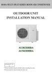
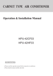
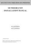
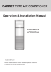
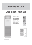
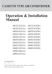
Cabinet unit Operation Manual HPU-90CA03T3 (Cooling Unit) No.0150504455 A CONTENTS Name of Parts 1 Parts and Functions 2 Operation points 3 Safety Precautions 4 Operation 5-6 Users' Attention 7 Maintenance 8-9 Trouble shooting 10 When problems occur 11 When troubles occur 12 Installation instruction 13-14 Installation procedure 15-26 Others 27-28 Name of Parts Indoor unit Outlet grill Operation panel Inlet grill Air outlet Outdoor unit Air inlet Air inlet Note: Open the power switch 12 hours before the unit running.Do not cut off the power when short time stop the unit (like one day and one night ),this is to protect the compressor. Do not block the air inlet and air outlet, otherwise the performance of the air conditioner may be lowered and it will make the protection device act. This is a cooling only unit,all the description about heating function is no meaning for this unit. Do not let the ID unit's outlet grill at downward position for a long time,when the unit runing at cooling or drying mode.Otherwise ,the water may be fall off from the outlet grill. 1 Parts and Functions 6 7 MODE TEMP 5 4 TEMP 3 FAN ON/OFF 2 1 8 1.Power ON/OFF Button Used for unit start or stop 2.FAN Button Used to select fan speed:AUTO,LOW,MID,HIGH. 3.TEMP Setting Button Used to set temperature. (Setting ranges: 16 C to 30 C) 4.MODE Button Used to select operation mode: AUTO COOL DRY FAN HEAT 5.Operation MODE Display Mode AUTO COOL DRY FAN HEAT Panel 6.FAN SPEED Display AUTO(Flash) LOW MID HIGH 7.LOCK State Display 8.TEMPERATURE Display Used to display set temperature and room temperature. 2 Operation points Anti-cold air blowing out When the ambient humidity is too high, During Heating operation, after starting the unit, the indoor fan motor will not rotate in COOLING or DEHUMIDIFYING mode, there may be water dropped in the immediately to prevent cold air from blowing air outlet. out. Operation of air conditioner MODE FAN SWING TEMP CLOCK SET TIMER SLEEP FILTER RESET RESET ON/OFF MODE FAN SWING TEMP CLOCK SET TIMER SLEEP FILTER RESET RESET ON/OFF ? 3-minute protection function Defrosting function If start the unit immediately only after it is turned off, the compressor will start after 3 minutes have elapsed to protect the compressor. MODE FAN SWING TEMP CLOCK SET TIMER SLEEP FILTER RESET RESET ON/OFF During Heating operation, when frost formed on the heat exchanger of outdoor unit, the air conditioner will defrost automatically for several minutes. During defrosting, both the fan of indoor and outdoor unit do not run. After finishing defrosting, the air conditioner will automatically resume operation. Change of fan speed In COOLING mode, the air sending is set at AUTO, when the indoor temperature is near the set temperature, the fan speed will lower automatically.In HEATING mode, when room temperature reaches the set temperature, the compressor will stop running, and the fan will change to LOW FAN or stop.In DEHUMIDIFYING mode, the fan speed will change automatically. MODE FAN SWING TEMP CLOCK SET TIMER SLEEP FILTER RESET RESET ON/OFF 3 Hint When the air conditioner is in Heating mode, it absorbs heat from outside and release to indoors. So the outdoor temperature may affect the Heating effect. Safety Precautions Notice Do not put or use any spray near the air conditioner, and do not directly spray to the air conditioner. The system should never be used for any other purposes than intended such as for preservation of food, flora and fauna, precision devices or work of art. Do not put the fire devices in the places, which the air from the air conditioner can directly blow. It may cause the fire devices cannot burn completely. It may cause deterioration of the articles. Otherwise it may cause fire. Only use the proper specified fuse. Do not install the system where the air outlet may directly reach the flora and fauna. If use metal wire or copper wire to replace the fuse, it may cause trouble and fire accident. It will not be good for their health. Do not use the power switch to turn on or off the air conditioner. ON OFF It may cause fire or Creepage. When operating the system simultaneously with a combustion apparatus, indoor air must be ventilated frequently.* Insufficient ventilation may cause the danger of lack of oxygen. Do not use such equipment as a water heater, etc., around the indoor unit or the wire controller. When cleaning, please stop the unit and cut off the power first. Do not perform cleaning, when the indoor fan motor is rotating in high speed. Do not put the water containers, such as vase, on the unit. If the water enters If the system is operated at the vicinity of such into the unit and damages equipment that generates steam, condensed the electric insulation material, water may drip during cooling operation or it it may cause electric shock. may cause Creepage or short-circuit. Safety precautions when moving, reinstalling and repairing the air conditioner Do not refit the air conditioner. When repair is needed, please contact your dealer. Warning When moving the air conditioner to another installation place, please contact the dealer or the professional installer. Improper repair may cause water leakage, electric shock and fire accident. Improper moving and reinstallation may cause water leakage, electric shock and fire accident. Applicable ambient temperature range: Indoor Maximum: D.B / W.B Minimum: D.B / W.B 32 18 / 23 / 14 Outdoor Maximum: D.B / W.B Minimum: D.B 52 / 32 21 Cooling 4 Operation AUTO, COOL , HEAT and DRY Operation LOCK MODE TEMP TEMP FAN 4 ON/OFF 5 1. Unit start Press ON/OFF button,unit starts. Previous operation status appears on LCD (except for TIMER,SLEEP and SWING setting) 2.Select operation mode Press MODE button. At each press, operation mode changes as follows: AUTO COOL DRY HEAT FAN Then select AUTO run or select COOL operation or select DRY operation or select HEAT operation or select FAN operation 3.Temperature setting Press TEMP button. Every time the button is pressed, temp. setting increases 1 C; if the button is kept pressed, temp. setting will increase quickly. Every time the button is pressed, temp. setting decreases 1 C, if the button is kept pressed, temp. setting will decrease quickly. Set proper temperature 4.Adjust FAN button Press FAN button. At each press, fan speed changes as follows: AUTO(Flash) LOW MID HIGH Air conditioner will run at the selected fan speed. COOL operation starts when room temp.is higher than temp. setting. Ultra-low air flow Temp. setting +2 C Temp.setting On reaching temp.setting +2 C, unit will run in mild DRY mode. 5. Unit stop Press ON/OFF button,unit stops. In FAN mode, the temperature setting is not displayed on LCD,and "Auto Fan" not available. In DRY mode, when room temperature becomes 2 C higher than temperature setting, unit will run intermittently at LOW speed regardless of FAN setting. When room temperature is lower than temperature setting, unit will only run FAN operation. In HEAT mode,warm air will blow out after a short period of time due to cold-draft prevention function. In Auto mode,unit will adjust fan speed according to room temperature automatically. 5 Operation Fan Operation LOCK MODE TEMP TEMP FAN ON/OFF 4 1.Unit start Press ON/OFF button to start your air conditioner. Previous operation status appears on LCD (except for TIMER, SLEEP, and SWING setting). 2.Select operating mode Press MODE button. At each press, operation mode changes as follows: AUTO COOL DRY HEAT FAN Then select FAN 3. Adjust fan speed Press FAN button. At each press, fan speed changes as follows: Air conditioner will run at the selected fan speed. 4. Unit stop Press ON/OFF button to stop unit. About FAN mode When the air conditioner runs in FAN mode, it is not possible to select AUTO FAN or to set temperature. 5. Warning:cooling only types are not with functions in heating mode. 6 Users Attention Do not press tightly with the LCD part of the wire controller to avoid damage of it. Set proper room temperature Not too low or high and make every people in the Heating is room Cooling is 18~23¡ 26~28¡ feel comfortable. Do not let the cold air blows directly to human body for a long time and do not make the room temperature drop too low. Otherwise, it may cause uncomfortable or bad to your health. The airflow cannot directly blow to the pets and plants. Otherwise, pets and plants may be hurt. The room should often ventilate. After a long-time of using air conditioner, the room must be ventilated. Do not keep the doors and windows open Otherwise, it may lower the efficiency of the air conditioner. Television, radio and acoustics, etc. equipment should keep over 1m from indoor unit and wire controller. Otherwise, they may disturb the image and cause noise. Do not put any drying devices under the indoor unit. The heat may cause the deformation of indoor unit. 7 If do not use the air conditioner for a long time, it is necessary to cut off power. If do not cut Cut off power off power, the unit may consume power. In order to protect the unit, before using the air conditioner again, turning on the power at least 12 hours in advance. The windows should be hung with curtains or blinds. Do not let the sun shine directly shine in the room; do not let the outdoor air enter room. The articles must keep dry cannot be put under the indoor unit. When the humidity is over 80% or the drainage outlet is blocked, the indoor unit may drop water. Do not put articles around the air inlet and outlet. This kind of obstacle can lower the efficiency of the air conditioner or cause unit trouble. The air conditioner can only be used in air conditioning. It can not be used in other purpose. Do not use the air conditioner in some specific purpose, such as storage or protect food, animals, plants, precise instrument and artwork, otherwise, the quality of them may be declined. Maintenance Disconnect power supply Don't touch it with wet hand Don't wash with hot water or solvent to clean the unit Remove air inlet grille First cut off the power supply, then turn the embedded part of air inlet grille upwards, finally use cross-shaped screwdriver to screw off the screw. Air filter cleaning Use water or vacuum cleaner to clean it. If it is extremely dirty, wash it with neutral detergent or soap water. Wash it with clean water and install it after complete dry. Caution: Don't use hot water over 40 C, as this may cause damage to air filter. Wipe air filter carefully. Indoor and outdoor cleaning 40¡ Clean it with warm and wet cloth or with neutral detergent, then wipe it dry with clean and soft cloth. If air conditioner is very dirty, clean it with cloth soaked in neutral detergent,then wipe off the detergent with clean water. Don't use water higher than 40 C , which will cause discoloring and deformation. 40¡ Don't use insecticide or other chemical detergents. 8 Maintenance After season maintenance Let the unit run in Fan mode for half a day in a fine weather to dry completely the unit inside. Turn off the unit and pull out power plug. There might be certain power consumption even if unit is stopped. Clean air filter and indoor unit, cover outdoor unit after cleaning. Before season maintenance Check if there are obstacles at inlet and outlet of indoor and outdoor unit, whick will reduce unit efficiency. Don't fail to attach air filter after making sure it is cleaned. Dust will enter into unit causing damages or faults if it is running without air filter. To protect compressor at start, please connect external power supply to the unit 12 hrs prior to starting. Also please keep the power supply switch ON during the whole season. 9 Trouble shooting Followings are not problems Sound of water flowings are not problems. During unit start and operation or at stop, a swishing or gurgling noise may be heard. This noise is generated by refrigerant flowing in the system. Sound of cracking is heard. During unit operation, a cracking noise may be heard. This noise is generated by the casing expanding or shrinking because of temperatuer changes. Smells are generated. This is because the system circulates smells from the interior air such as the smell of cigarettes or the painting on the unit. During operation, white fog or steam When unit is running at places like restaurant where dense edible oil fumeis always exist, this will happen. comes out of indoor unit. In cooling operation, unit switches to fan operation. Unit will not restart after stop. Won't start? To prevent frost from accumulating on indoor heat exchanger, unit will switch to fan operation for a while then resume cooling operation. Though ON/OFF button is set to ON, unit won't resume cooling,dry or heating operation in 3 min after it is stopped, this is because of 3min-delay protection circuit. Please wait 3 minutes No outlet air or fan speed can't be changed in dry mode. In heating operation, water or steam are blown out of indoor unit. In heating operation, indoor fan won't stop even if unit is stopped. Unit will reduce fan speed repeatedly and automatically if room temp. is too low in dry operation. This occurs when frost accumulated on the outdoor unit is removed. (during defrosting operation) After unit stops, indoor fan will go on running until indoor unit cools down. 10 When problems occur? Before ask for services, please first check your unit against following. Air conditioner won't start. Is power supply switch turned on? Power supply switch is not set at ON. Is city power supply normal? Is leakage current breaker activated? This is very dangerous, please disconnect power supply immediately and contact your dealer. Power failure? Poor cooling or heating Are operation controlls adjusted correctly as specified? Is air filter too dirty? Are there any obstacles at inlet or outlet grill? Proper temp Are horizontal louvers at up position (in heating mode)? Any doors or windows left open? Poor cooling Is there any direct sunlight in the room? If there are unexpected heat sources in the room? Too many people in the room? If your unit still can't work properly after above mentioned checks, or following problems occur, please stop it immediately and contact your dealer. Fuses or circuit breakers often blow out. Water comes out in cooling/dry operation. Operation is abnormal or sound is heard. If the fuse on PC board is broken please change it with the type of T.6.3A/250VAC. 11 When Troubles Occur ? Find the following troubles occur, please stop the unit and cut off power, then contact the after-sales service worker. Warning If finding any abnormal phenomena (e.g. smell of burnt), please cut off power and ask help for after-sales service personnel. If still use the air conditioner under this condition, the unit may be damaged and maybe cause electric shock or fire, etc. accidents. After taking the following measure, please contact the commissioned service center. Symptom The fuse and creepage breaker are often blown out; Cut off power or the operation switch works abnormally. In Cooling or Dehumidifying operation, there is water leakage; Cut off power and inform your commissioned service center. Malfunction Error display Failure description Code on wired controller Room temp. sensor abnormal E1 Indoor coil temp. sensor abnormal E2 Outdoor temp. sensor abnormal E3 Outdoor coil temp. sensor abnormal or compressor discharge temperature protection abnormal E4 Over-current malfunction E5 High / Low pressureabnormal E6 Communication malfunction between indoor PCB and wired controller E8 Communication malfunction between indoor PCB and outdoor PCB E9 The float switch malfunction E0 12 Installation instruction Before installing, do read this Safety precautions carefully to guarantee the proper installation. The below attentive matters are divided into Warning and Note two parts. When the wrong installation occur, it is very possible death and severe injury and other serious accidents will happen. For those items are listed in Warning part. But even the items listed in Note part can also cause serious accidents. Above all, both the two parts are very important contents related to safety, so they must be obeyed. After finishing the installation work, do test run to verify everything is normal. After that please explain the using and maintenance methods to the user. Additionally, give this installation manual and operation manual to the user and ask them to keep it properly. Warning The commissioned repair center shall do the installation work. If you do the installation work by yourself, the improper installation will cause water leakage, electric shock fire and other accidents. The installation work shall be in line with what the installation manual specified. If installation is not proper, water leakage, electric shock, fire and other accidents will occur. Install the air conditioner to a place where can definitely stand its weight. The air conditioner can not be installed on a nonmetal bracket (such as theft guard net). Places not firm enough will cause drop down of unit resulting in body hurt. The installation work shall be preventive to typhoon and earthquake. If the installation work is not met with the requirements, overturn of the unit will occur resulting in accidents. Using the specified cable to do wiring work and connecting firmly and properly. Fix the connecting part of the terminals to prevent it from the external force. Improper connection and fixing will cause heating and fire etc. accidents. Wiring shall be kept in correct shape avoiding extrusion. After installation, the electric box cover and the external panel shall not nip the wire. Improper installation will cause heating and fire etc. accidents. When setting or moving the air conditioner do not let the air and things alike get into the refrigeration system except the specified refrigerant (R22). If air and other things enter, abnormal high pressure will occur, which easily cause break and body injuries etc. accidents. When installing, do use the accessories or specified parts. If not using the parts specified by our company, water leakage, electric shock, fire and refrigerant leakage will occur. Do not lead the drain hose to drain where the sulfur gas may be involved. Otherwise, the poisonous gas will enter into the indoor. During installation, if refrigerant leakage occurs, do the ventilation work immediately. As soon as the refrigerant gas meets fire, poisonous gas will be produce. After installation, confirm there is no leakage of refrigerant. If the refrigerant gas enters into room and meet the air blowing heater, heater or stove etc. fire source, the poisonous gas may be produced. Do not install the unit in a place where the combustible gas may be leaked. In any case the combustible gas leaks and accumulated around the unit, fire accident will occur. The drain hose should be correctly installed according to the installation manual to ensure smooth drainage, and take proper heat preservation measure to prevent from dew. Improper pipe installation may cause water leakage result in wet the indoor articles. Do heat insulation work to the refrigerant gas pipes and liquid pipes to reach the purpose of heat preservation. If the heat insulation measure is not sufficient, water generated by condensing dew will drip leading to wet the floor and indoor articles. Note Do grounding work. Do not connect the grounding wire to gas pipe, tap, lighting rod or telephone line. Improper grounding will cause electric shock. In some places the creepage breaker shall be installed. If do not install the breaker, electric shock may occur. After electric installation, power on them to do electric leakage test. 13 Installation instruction Notice This manual can not include all kinds of conditions, if you have new requirements and questions, please contact with local Haier Sales Center. Warning Before installing the unit, please read this manual carefully. Improper installation may cause accidents and make unit damage or death. Installation tools 1. Screw driver 3. 70mm dia. hole core drill 5. Spanner (14, 17, 27mm) 7. Flaring tool 9. Nipper 11. Measuring tape 13. Refrigerant oil 2. Hacksaw 4. Spanner (dia. 17, 27mm) 6. Pipe cutter 8. Knife 10. Gas leakage detector or soap water 12. Reamer 14. Lead-solder tool Standard accessories Following parts shall be field supplied Mark Parts name A Adhesive tape B Pipe clip C Connecting hose D Drain hose E Insulation material F Putty 14 Installation procedure 1. Before installation [Before finishing installation, do not throw the attached installation parts away.] Confirm the route to carry the units to the installation place. Do not remove the package of the unit, before carrying it to the installation place. When have to remove the package, use a soft material or protection board with rope to lift the unit to prevent the unit from damage or bumping scrape. 2. Selection of installation place Select the firm place that will not influenced by vibration and can bear the weight of the unit Select the place with easy drainage and place can perform outdoor unit pipe connecting. Select the place far away from heat source, vapor source and direct sunshine to avoid the causing of the trouble in operation parts and the deformation of the casing. Select the place where the cool air or warm air can evenly spread to every corner of the room. Select the place near power receptacle leaving sufficient space around the unit. (Referring to installation diagram) Avoid the following installation places Place with oil fog splash and much vapor (e.g. mechanical plant and kitchen, etc.) to prevent heat exchanger from performance lowering and plastic parts from corroding to damage. Place may generate or keep corrosive gas (sulfur dioxide, etc.), flammable gas (diluent, gasoline, etc.) to prevent heat exchanger from corroding, plastic parts from damage and flammable gas from causing fire accident. Hospital, etc. places near the machine generates electromagnetic wave or high frequency signal to prevent the mixed wave from causing wrong action of the control parts. Place can be blown by the sea wind (coastal area) to prevent the casing and heat exchanger from corroding. 3. Installation space (Indoor unit) please keep the spaces larger than the following dimension. 600 50 Unit (mm) 1000 50 600 50 600 15 Installation procedure indoor unit Installation of indoor unit Selection of installation place Place where it is easy to route drainage pipe and outdoor piping. Place away from heat source and with less direct sunlight. Place where cool and warm air could be delivered evenly to every corner of the room. Place near power supply socket. Leave enough space around the unit (refer to installation drawings). Fixing of the unit 1. Position of the wall hole Wall hole should be decided according to installtion place and piping direction. (refer to installation drawings) 2. Making a wall hole Drill a hole of 70mm dia. with a little slope towards outside. Install piping hole cover and seal it with putty after installation. INDOOR wall hole OUTDOOR UNIT wall thinkness 70mm ( Cross section of wall hole ) Fixing of indoor unit To prevent it from fall off, please fix the unit with fall-prevention fitting at wall and L-shaped metal at floor. Self-tapping screw all-prevention fitting metal (accessory) Wood screw Please install the whole unit horizontally,with a slop of 1 degree at front and rear,left and right. L-shaped metal (accessory) 16 Installation procedure indoor unit Installation of fall-prevention fitting metal: Fix the fitting metal to the wall by screws so that there is no clearance between them. With the unit set up vertically, fix the fitting metal to the unit with screws while making an adjustment at the long portion of the hole so that there is no clearance between the upper surface and the fitting metal. Installation of L-shaped metal Fix to the unit by screws so that there is no clearance between the fitting metal and the unit. After confirming that the unit has been set up vertically to the floor, fix it to the floor by bolt. Piping connection 1. Connecting method Apply refrigerant oil at half union and flare nut. To bend a pipe, give the roundness as large as possible not to crash the pipe. When connecting pipe, hold the pipe centre to centre then screw nut on by hand,refer to Fig. Be careful not to let sundries, such as sands enter the pipe. Forced fastening without centering may damage the threads and cause a gas leakage. Pipe dia Liquid pipe 12.7mm(1/2") 17 Fastening torque 42N.m Installation procedure Indoor unit 2. Piping connection of indoor unit Arrangement of piping and drainage pipe After opening inlet grill, you will see a control box as shown in the Fig. Remove the cover before working. Cut away, with a hammer or a saw, the lid for piping according to piping direction. Insulation material Copper tube Drain hose Connecting electric cable for indoor and outdoor unit According to the piping method, connect the piping on indoor unit with union of connecting pipe. Arrange the piping as per the wall hole and bind drain hose connecting electric cable and piping together with polyethylene tape. Insert the bound piping connecting electric cable and drain hose through wall hole to connect with outdoor unit. Arrangement of drain hose Drain hose shall be placed in under place. There should be a slope when arrange drain hose. Avoid up and down waves in drain hose. Indoor unit Up Slope Down Good Bad If humidity is high, drain pipe( especially in room and indoor unit ) must be covered with insulation material. 18 Installation procedure Indoor unit Main points of installation refrigerant pipe Please install the gas pipe and liquid pipe according to the following shown method. Please remove the cover piece on the gas pipe and the screw cap on the liquid pipe. A B ¢ Please connect the connecting pipes between indoor and outdoor unit according to the following method. a) When introducing the pipe from right side Use attached accessory <A> to connect the on-the-spot connecting pipe and gas pipe. A B b) When introducing pipe from rear side or left side Use attached accessory <A> to connect the on-the-spot connecting pipe and gas pipe. ¢ After finishing connection of connecting pipe, please do thermal insulation treatment by using the attached thermal insulation material. Otherwise, it may cause water leakage. 19 Installation procedure Outdoor unit Outdoor unit 1.GENERAL They can be mounted on a slab or rooftop. It is important to consult your local code authorities at the time the first installation is made. Check following points before attempting any installation: Structural strength of supporting members. Clearances and provision for servicing. Power supply and wiring. Location for minimum noise, where operating sounds will not disturb owner or neighbors. Location where there is no risk of combustible gas leakage. Location where external water drainage cannot collect around the unit. Location where roof runoff water does not pour directly on the unit. Provide gutter or other shielding at roof level. Don't locate unit in an area where excessive snow drifting may occur or accumulate. Provide a level concrete slab. To prevent transmission of noise or vibration, slab should not be connected to building structure. Some sort of sound-absorbing material should be placed between the condenser and the slab. A good material to use is rubber and cork pad. For rooftop application, make sure the building construction can support the weight and that proper consideration is given to the weather-tight integrity of the roof. The condensing unit contains moving parts and can vibrate. Therefore, sound is also a consideration in rooftop applications. ! WARNING - Install the unit securely in a place that can bear the weight of the unit. When installed in an insufficiently strong place, the unit could fall causing injury. 20 Installation procedure Outdoor unit 2.UNIT CLEARANCES 10" Min. Service Access 18" Min. 10 "Min. Service Access 10" 18" Min. 10 " Figure 1 The minimum clearances for the unit are illustrated in Figure 1. Condenser air enters from three sides. Air discharges upward from the top of the unit. Refrigerant tube and electrical connections are made from the service access area. The most common application will find the unit best located about 10" from back wall with connection side facing the wall. This application minimizes exposed tubing and wiring, minimizing the space for youngsters to run around the unit with subsequent damage to the tubing or wiring. In more confined application spaces, such as corners provide a minimum of 10" clearance on all air inlet sides. For service access to the compressor and control box, allow 18" minimum clearance. Ensure top is unobstructed. If units are to be located under an overhang, there should be a minimum of 36" clearance and provision made to deflect the warm discharge air out from the overhang. In order to have an unrestricted air flow, owners should be advised to avoid lawn mower discharge toward the unit depositing debris on the fin coil surface reducing the unit efficiency. .3.REFRIGERANT PIPING The refrigerant piping is very important as it affects the proper operation and efficiency of the air conditioning system. Note the following guidelines: OUTDOOR UNIT ADDITIONAL SUCTION LINE OIL TRAP FOR EACH 20 FOOT RISE OF PIPE PITCH SUCTION LINE TOWARD OUTDOOR UNIT 1/2" FOR EVERY 10' OF LINE 30m INDOOR UNIT ABOVE OR LEVEL TO OUTDOOR UNIT MAX. OUTDOOR UNIT LIQUID LINE INDOOR UNIT A 6' INVERTED LOOP LIQUID LINE INDOOR UNIT 30m MAX. OUTDOOR UNIT SUCTION LINE B-2 21 LIQUID LINE SUCTION LINE OIL TRAP WHEN INDOOR UNIT IS 4 FEET OR MORE BELOW OUTDOOR UNIT INDOOR UNIT INDOOR UNIT BELOW OUTDOOR UNIT B-1 Installation procedure Outdoor unit Only refrigeration-grade copper piping (dehydrated and sealed) should be used. Take extreme care to keep the refrigerant tubing clean and dry prior to and during installation. If in doubt, blow out the tubing with dry nitrogen to remove any chips or debris before connection. Always keep tubing sealed until it is in place and the connections are to be made. Refrigerant piping should be as short as possible, with a minimum of elbows or bends, to avoid capacity loss and increased operating costs. Refrigerant lines must be adequately supported. If metal strapping is used to secure the tubing, do not allow the strapping to directly contact the tubing. Use a closed cell insulation to separate the strapping from the tubing. Do not kink or twist the tubing. Refrigerant piping should not be installed in a cement slab, as this limits access to the refrigerant should a leak be suspected. To ensure good oil return to the compressor, it is important to pitch the horizontal suction line toward the compressor, approximately 1/2" for every 10' of line. The maximum connection pipe is 50m ,the maximum drop different between indoor unit and outdoor unit is 30 m Line Insulation Suction line requires insulation in order to prevent condensation from forming on the piping and to prevent heat gain caused by surrounding air. Generally 3/8" wall thickness of Armflex or equivalent is satisfactory. In severe application (hot, high humidity areas) greater thickness may be required. Apply the line insulation by sliding it on the sealed tuing before cutting and making connections. Liquid line does not necessarily need insulation, however, if they are exposed to high ambient temperatures (i.e. kitchen, boiler rooms, hot attics & rooftop surface), then, they should be insulated. Make sure to use the proper size tubing for the liquid line to prevent liquid refrigerant flashing to a vapor within the liquid line. Do not allow the vapor line and liquid line to touch together. This would cause an undesirable heat transfer resulting in capacity loss and increased power consumption. Tubing connection ! CAUTION - Use extreme caution in removing the caps from the suction and liquid line fittings, as there is pressure present. A fitting is on the liquid line to remove pressure. ! CAUTION - Condensing units are charged with refrigerant. Condensing unit liquid and suction valves are closed to contain the charge within the unit. Do not force the valve stem against the retaining ring. If the valve stem is backed out past the retaining ring, system pressure could force the valve stem out of the valve body and possibly cause personal injury. 22 Installation procedure Outdoor unit Matters needing attention Never use oxygen,flamable and poisonous gases for the leak test. Indoor Three-way valve fully closed(gas side) Outdoor Solder joint Low-pressure High-pressure gauge gauge Solder joint Access hole VL VH Gauge distributor 6.4 Tightly closed Solder joint Indoor unit Detailed diagram of the three-way valve Access hole Relief valve 6.4 Copper pipe Outdoor unit Three-way valve fully closed liquid side To the gauge distributor (Liquid side)three-way valve Nitrogen bottle Copper pipe (Gas side)three-way valve To the unit (Gas side ) access hole (Liquid side)access hole To the unit Field tube installation Field tube installation Step 1:Charge for more than 3 minutes under 0.3MPa(3.0kg/cm2g) Step 2:Charge for more than 3 minutes under 1.5MPa(15kg/cm2g) --Serious leakage may be found. Step 3:Charge for more than 24 hours under 3.0MPa(30kg/cm2g) --Small leakage may be found. Check for pressure decrease Without pressure decrease-Pass With pressure decrease-Check for leakge. There will be a 0.01MPa(0.1kg/cm2g) pressure change for every 1 C ambient temperature change during the 24-hour pressure charge.It should be corrected during the test. 23 Installation procedure Outdoor unit Check for leakage In the case of pressure decrease during steps 1 to 3 ,check the joints with the ear,hand or soapsuds for leakage.Repair it by welding or tighten the connecting nut up. Vacuum Pumping Use vacuum pump to evacuate the air.Never use the refrigerant for the evacuation. Drain off the nitrogen gas after the leak test and then connect the vacuum pump as shown in the figure below. The vacuum pumping must be done from both the liquid and gas inlets. Low-pressure High-pressure gauge gauge Indoor Three-way valve fully closed(gas side) Outdoor Solder joint Solder joint Access hole VL VH Gauge distributor 6.4 Tightly closed Solder joint Indoor unit Detailed diagram of the three-way valve Relief valve 6.4 Copper pipe Access hole Outdoor unit Three-way valve fully closed liquid side To the gauge distributor (Liquid side)three-way valve To the unit Nitrogen bottle Copper pipe (Gas side)three-way valve (Gas side ) access hole (Liquid side)access hole To the unit Field tube installation Field tube installation Use a vacuum pump with high degree of vacuum(below-755mmHg) and large volume displacement (above 40L/min) The pumping time depends on the length of the connecting pipe.Generally,it takes about 2-3 hours. Make sure that the Y-shaped valves on both the gas and liquid sides are closed before pumping. If the vacuum can no reach-755mmHg within 2 hours,continue pumping for another 1 hour. If the vacuum can no reach-755mmHg after more than 2 hour's pumping,close the valves VL and VH onthe gauge distributor and stop pumping.One hour later,check the vacuum again.If the vacuum has changed,it means there is a leakage.Repair it. After the above steps,replace the vacuum pump with the refrigerant pump and refill refrigerant. 24 Installation procedure Outdoor unit Adding refrigerant Refrigrant must be added in liquid state. Refrigerant bottle swith or without a siphon tube can be refilled with refrigerant upright or upside down,Respectively. Containers for R22 refrigerant must be marked with R22 R22 refrigerant cannot share the same instrument distributor and filling pipes. Refrigerant charge After finished vacuum the system,charge the vacuum to the refrigerant pump,chargeing the refrigerant. Calculation of the refrigerant charge Note:when unit shipping out of the factory,charge the refrigerant not including the connstruction procedure charged parts. The calculation of the refrigerant charging: When the connection pipe(L)<=5 meters, not need to add refrigerant;If the connection pipe (L)> 5 meters,we need recharge the 60g refrigerant per add 1 meter. That is :the quantity of refrigerant charging=(L-5)*60(g) Refill refrigerant When the outdoor valve is shut,fill the refrigerant from the access hole at the gas and liquid sides. If the required filling is impossible,open all the gas and liquid valves,then slightly shut the gas valve, run the compressor and fill the refrigerant from the access hole at the gas side.Now adjust the gas valve to control the refrigerant flow,which will be gasified during absorption by the system. If there is insufficient refrigerant in the system caused by leaks,refill it after the remaining refrigerant is recollected. Open all valves Open all the valves of the outdoor unit. Heat isolation of the pipes Separate isolation should be made for the liquid and gas pipes. Materials used for the pipe isolation at the gas side must withstand above 120 C temperature. 25 Installation procedure Electric wiring Note: All the wires should be copper core wires. The power cable of indoor unit should be equipped according to the operation manua of indoor unit. Before finishing vacuumizing the refrigerant pipe system, do not supply power to indoor unit. When connecting the indoor & outdoor wire, check the number of the indoor & outdoor terminals, the terminals with the same number connected together with one wire. Incorrect wiring will damage the controller of the air conditioner or make the unit work abnormally. The air conditioner must use special power circuit and special air switch (40A), groundign wire. The wiring work should be done by a qualified electrician according to the national wiring rule. The creepage breaker must be installed. The grounding line and the neutral line of the receptacle must be strictly separated. It is incorrect to connect the neutral line with the grounding line. The connection type of power cord is Y connection. If the soft power cord is damaged, to avoid risk, it must be replaced by the manufacturer or their specific repair department or similar professional worker. Wiring method 1.The wiring method of orbicular terminal For the connection wire which end is orbicularterminal, its wiring method is as the right figure shown. Dismantle the screw and put it through the ring at the end of the connection wire, then connect it to the terminal block and tighten the screw. 2.The wiring method of straight terminal For those connection wires whose end are not orbicular terminals, their wiring method is: Loosen the connecting screw, insert the end of the wire directly into the terminal block, and then tighten screw. Pull the wire outwards slightly to confirm it is held tightly. 3.Pressing method of connection wire: After wiring, the connection wire must be pressed with wire holding clamp. The wire holding clamp should press on the out cover of the connection wire. As the right figure shown: Connect wire between indoor & outdoor unit As the wiring diagram show to arrange the connection wire. Note: The terminal block's mark at the two ends of the connection wire should be corresponding one by one, otherwise the air conditioner cannot work normally. The wiring method of orbicular terminal Wrong pressing Correct pressing Terminal block Wire holding clamp (Sketch map) Terminal block of indoor unit 1 2 3 1 2 3 Y/G Y/G Power supply: 380-400V~,3N,50Hz L1 L2 L3 N Terminal block of outdoor unit Terminal block of outdoor unit The power cable and connecting cable are selfprovided. The power cable shoule be 5x6.0mm2; the connecting cable should be 4x1.0mm2. Selection of size of power supply and interconnecting wires. Item Model HPU-90CA03T3 Circuit breaker Power source wire size Phase Switch breaker Overcurrent protector (minimum) (A) rated capacity (A) 3 40 30 26 6.0mm2 Earth leakage breaker Switch breaker Leak current 40 30mA Others 1. Power supply The parameter of power cord is over 2.5mm2. Air conditioner must use an exclusive line (over 30A) When installation air conditioner in a wet place, try to use a circuit breaker against Current leakage. For installation in other places, use circuit breaker as far as possible. The breaker of the air conditioner should be all-pole switch ; and the distance between its two contacts should be no less 3 mm. Such means for disconnection must be incorporation in the fixed wiring 2. Pipe cutting and flaring Be sure to carry out deburring after pipe cutting with a pipe cutter. Insert flaring tool to make a flare. A Pipe dia. Flaring tool Liquid pipe Correct 12.7mm (1/2") Dimension A(mm) 1.2 ~ 2.0 Incorrect Lean Damaged flare Crack Partial Too outside Installation inspection and test run: Please operate unit according to this Manual. Items to be checked during test run. Please made a " "in " " Are there any gas leakage? How is insulation at piping connection carried out? Are electric wires of indoor and outdoor unit firmly inserted into terminal block? Is electric wiring of indoor and outdoor securely fixed? Is drainage securely carried out? Is earth line ( grounding ) securely connected? Is power supply voltage abided by the code? Is there any noise? Is control display normal? Is cooling operation normal? Is room temp. regulator normal? 27 Others 1.Calculation of refrigerant density Calculation will be made according to the following methods: 1) Total refrigerant content of each system (kg) =content of 1 outdoor system + refilled refrigerant Content of 1 outdoor system:Factory filled refrigerant Refilled refrigerant:Filled content during installation according to the diameter and length of the liquid piping. 2) Calculation of the minimum room space (m3). 3) Calculation of refrigerant density Total refrigerant content Minimum room space Refrigerant density:0.3(kg/m3) 2.Preventive measures against excess of critical value 1) Make ventilation holes Ventilation holes should be built above and under the door.The area of each hole should not be smaller than 0.15% of the room space.Holes can be made directly in the wall. 2) Reduce the filling content of refrigerant Filling content of refrigerant can be reduced by shortening the distance between the indoor and outdoor units. By reducing the capacity of the outdoor unit. When outdoor unit be made up of several units.the outdoor capacity of each system should reduce.So the refrigerant content of system reduce. 3) Install ventilation fans. Users can install uninterrupted ventilation fans to keep the refrigerant density under the critical value. If uninterrupted ventilation is impossible,a combined fanning and alarming device should be installed in its stead (through which immediate ventilation is possible when leak occurs). (See the figure below) An example Ventilation fan and gas leak alariming device The gas leak alarming device should be installed at refrigerant gas stagnation areas 28 Vertilation opening