1
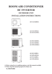
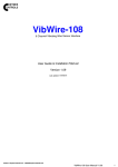
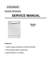
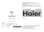
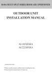
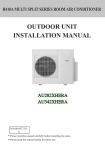
ROOM AIR CONDITIONER
OUTDOOR UNIT
INSTALLATION INSTRUCTIONS
CONTENTS
AU182AEEAA
Name of Parts----------------------1
Safety Cautions------------------2-3
Installation Procedure---------4-13
AU242AGEAA
AU282AHEAA
AU28NAHEAA
AU36NAIEAA
AU362AIEAA
AU48NAIEAA
AU60NAIEAA
No.0010577959
D
Before using the air conditioner,please read this manual carefully.
Please keep this manual properly for future use.
Name of Parts
AU182AEEAA
AU242AGEAA
Air inlet
Air inlet
Air outlet
Air outlet
Compressor
Compressor
(Inside of unit)
(Inside of unit)
Air inlet
AU282AHEAA
AU28NAHEAA
Air outlet
Compressor
(Inside of unit)
Air inlet
AU36NAIEAA
AU362AIEAA
AU48NAIEAA
AU60NAIEAA
Air outlet
Compressor
(Inside of unit)
1
Safety Cautions
Carefully read the following information in order to operate the airconditioner
correctly.
Below are listed three kinds of Safety Cautions and Suggestions.
WARNING! Incorrect operations may result in severe consequences of death or serious injuries.
CAUTION! Incorrect operations may result in injuries or machine damages; in some cases may
cause serious consequences.
INSTRUCTIONS: These information can ensure the correct operation of the machine.
Be sure to conform with the following important Safety Cautions.
The Safety Cautions should be at hand so that they can be checked at any time when needed.
If the conditioner is transferred to the new user, this manual should be as well transferred to the
new user.
WARNING!
Don't dismantle the outlet of the
outdoor unit.
If any abnormal phenomena is found
(e. g.smell of firing), please cut off the
power supply immediately, and contact
the dealer to find out the handling
method.
The exposure of fan is very dangerous
whichmay harm human beings.
In such case, to continue using the
conditioner will damage the conditioner,
and may cause electrical shock or fire
hazard.
switch
off
When need maintenance and repairment,
call dealer to handle it.
After a long time use of air-conditioner
the base should be checked for any
damages.
If the damaged base is not repaired, the
unit may fall down and cause accidents.
Incorrect maintenance and repairment
may cause water leak, electrical shock
and fire hazard.
2
Safety Cautions
WARNING!
Installed electrical-leaking circuit
breaker.
No goods or nobody is permitted to
placed on or stand on outdoor unit.
It easily cause electrical shock without
circuit breaker.
The falling of goods and people may
cause accidents.
Air-conditioner can't be installed in
the environment with inflammable
gases because the inflammable gases
near to air-conditioner may cause fire
hazard.
Please let the dealer be responsible for
installing the conditioner.
Don't operate the air-conditioner with
damp hands.
Incorrect installation may cause water
leak, electrical shock and fire hazard.
Otherwise will be shocked.
Call the dealer to take measures to
prevent the refrigerant from leaking.
If conditioner is installed in a small
room be sure to take every measure in
order to prevent suffocation accident
even in case of refrigerant leakage.
Only use correctly-typed fuse.
May not use wire or any other materials
replacing fuse, other-wise may cause
faults or fire accidents.
When conditioner is deinstalled or
reinstalleddealer should be responsible for them.
Incorrect installation may cause water
leaking, electrical shock and fire hazard.
Connect earthing wire.
Earthing wire should not be connected to the gas pipe, water pipe,
lightning rod or phone line, incorrect earthing may cause shock.
Use discharge pipe correctly to ensure
efficient discharge.
Incorrect pipe use may cause water
leaking.
Earthing
3
Installation Procedure
Installation of outdoor unit
1. Accessories
Edging
"Edging" for protection of electric wires from an
opening edge.
2. Selection of the place of installation
Select the place of installation satisfying the following conditions and, at the
same time, obtain a consent from the client or user.
Place where air circulates.
Place free from heat radiation from other heat sources.
Place where drain water may be discharged.
Place where noise and hot air may not disturb the neighborhood.
Place where there is not heavy snowfall in the winter time.
Place where obstacles do not exist near the air inlet and air outlet .
Place where the air outlet may not be exposed to a strong wind.
Place surrounded at four sides are not suitable for installation. A 1m or more
of overhead space is needed for the unit.
Mount guide-louvers to place where short-circuit is a possibility.
When installing several units, secure sufficient suction space to avoid short
circuiting.
(1) Open space requirement around the unit
L3
Air inlet
L2
500
(Servicing
space)
Air
inlet
Air outlet
L1
Note :
(1). Fix the parts with screws
(2).Don't intake the strong wind directly to the
outlet air-flow hole.
(3).A one meter distance should be kept from the
unit top
(4).Don't block the surroundings of the unit with
sundries
Unit: mm
Case
I
II
III
open
open
500
L2
300
300
open
L3
150
300
150
Distance
L1
NO
Wind direction
(2) Installation where the area with strong winds.
Install the unit so that the air outlet section of the unit must NOT be faced
toward wind direction.
4
Installation Procedure
Installation of outdoor unit
3. Installation of outdoor unit
(1) Installation
Fix the unit in a proper way according to the condition of a place where it is
installed by referring to the following .
AU182AEEAA
(a) Concrete foundation
(b) Foundation anchor
Unit
Unit
Anchor bolt
Concrete foundation
Concrete foundation
To fix by bolts
Anchor bolt
AU242AGEAA
(a) Concrete foundation
(b) Foundation anchor
Unit
Unit
Anchor bolt
Concrete foundation
Concrete foundation
To fix by bolts
Anchor bolt
AU282AHEAA AU28NAHEAA
(a) Concrete foundation
(b) Foundation anchor
Unit
Anchor bolt
Unit
Concrete foundation
Concrete foundation
To fix by bolts
Anchor bolt
AU362AIEAA AU36NAIEAA AU48NAIEAA AU60NAIEAA
(b) Foundation anchor
(a) Concrete foundation
Unit
Unit
Anchor bolt
Concrete foundation
Concrete foundation
To fix by bolts
Anchor bolt
Note: (1) Give enough room for the concrete foundation to fix by anchor bolts.
(2) Place the concrete foundation deep enough.
Install the unit so that the angle of inclination must be less than 3 degrees.
5
Installation Procedure
Installation of outdoor unit
(2) Installation sketch of outdoor unit
AU182AEEAA
780
Power Wiring Terminal
270
640
Power Wiring
Distribution Hole
25
500
AU242AGEAA
860
Power Wiring Terminal
Power Wiring
Distribution Hole
308
335
730
630
AU282AHEAA AU28NAHEAA
948
Power Wiring Terminal
25
6
340
840
Power Wiring
Distribution Hole
380
580
Installation Procedure
Installation of outdoor unit
AU362AIEAA AU36NAIEAA AU48NAIEAA AU60NAIEAA
948
Power
wiring
Terminal
25
1250
340
380
580
4. Refrigerant piping
(1) Outline piping
AU182AEEAA
Flare connection
3-way stop valve
Gas pipe
Outdoor
unit
Indoor
unit
Liquid
pipe
Flare connection
AU242AGEAA AU282AHEAA AU28NAHEAA
AU48NAIEAA AU60NAIEAA
2-way stop valve
AU362AIEAA AU36NAIEAA
Flare connection
3-way stop valve
Gas pipe
Outdoor
unit
Indoor
unit
Liquid
pipe
Flare connection
7
3-way stop valve
Installation Procedure
Refrigerant piping
(2) Piping size
Liquid pipe
6.35x0.8mm
Gas pipe
12.7x1.0mm
Liquid pipe
9.52x0.8mm
AU182AEEAA
AU242AGEAA
AU282AHEAA
AU28NAHEAA
AU36NAIEAA
AU362AIEAA
AU48NAIEAA
AU60NAIEAA
90+0.5
Gas pipe
15.88x1.0mm
Liquid pipe
9.52x0.8mm
Gas pipe
19.05x1.0mm
Install the removed flare nuts to
the pipes to be connected, then
flare the pipes.
(3) Limitations for one way piping length and vertical height difference.
Model
One way piping length
Vertical height difference
(between indoor and outdoor)
AU182AEEAA
less than 20 m
less than 10 m
AU242AGEAA AU282AHEAA
AU28NAHEAA
less than 30 m
less than 15 m
AU362AIEAA AU36NAIEAA
AU48NAIEAA AU60NAIEAA
less than 50 m
less than 30 m
Precautions for refrigerant piping
Do not twist or crush piping.
Be sure that no dust is mixed in piping.
Bend piping with as wide angle as possible.
Keep insulating both gas and liquid piping.
Check flare-connected area for gas leakage.
(4) Piping connection
Connecting method (indoor unit)
Apply refrigerant oil at half union as large and flare nut.
To bend a pipe, give the roundness as possible not to crush
the pipe.
When connecting pipe, hold the pipe centre to centre then
screw nut on by hand, refer to Fig.
Be careful not to let foreign matters, such as sands enter
the pipe.
Pipe dia
Fastening torque
Liquid pipe 6.35mm
14.2-17.2N.m
Liquid pipe 9.52mm
32.7-39.9N.m
Gas pipe 12.7mm
49.5-60.3N.m
Gas pipe 15.88mm
61.8-75.4N.m
Gas pipe 19.05mm
97.2-118.6N.m
Forced fastening without centering
may damage the threads and cause a
gas leakage.
8
Installation Procedure
Refrigerant piping
5. Air discharging method
After finishing connection of refrigerant pipe, it shall perform air tightness test.
The air tightness test adopts nitrogen tank to give pressure according to the pipe connection
mode as the following figure shown.
The gas and liquid valve are all in close state. In order to prevent the nitrogen entering the
circulation system of outdoor unit, tighten the valve rod before giving pressure (both gas
and liquid valve rods).
Low pressure peizometer
High pressure peizometer
Indoor
3-way valve totally closed
(Gas side)
Outdoor
Completely tightened
Completely tightened
Flare part
Discharging valve
Flare part
Manhole
VL VH
Meter separator
Dropping valve
Nitrogen tank
Indoor units
Outdoor units
3-way valve totally closed
(Liquid side)
First step: 0.3MPa (3.
0kg/cm2g) pressurize
over 3 minutes.
Second step: 1.5Mpa
(15kg/cm2g) pressurize
over 3 minutes. Large
leakage will be found.
LINE
PRESSURE
GAUGE
CYLINDER
PRESSURE
GAUGE
TUBING
BRING
BRAZED
SWEAT
JOINT
Third step: 3.0 MPa
(30kg/cm2g) pressurize
about 24 hours. Little
leakage will be found.
LARGE
SLIP-ON
CONNECTOR
CYLINDER
OF
NITROGEN
SERVICE
HOUSE
Check if the pressure drops
The pressure does not drop-passed
The pressure drops-check the leaking point.
From pressurizing to 24 hours later, each 1* difference of ambient temperature
will make 0.01MPa(0.1kg/cm2g) pressure change. It shall be corrected during test.
Checking the leaking point
In the first to third test steps, if the pressure drops, check the leakage in each joint
use sense of hearing, feeling and soap water, etc. methods to find the leaking point.
After confirming the leaking point, welding it again or tighten the nut tightly again.
9
Installation Procedure
Refrigerant piping
6. Piping and indoor unit vacuumizing
Use vacuum pump to perform vacuumizing. It is strictly forbidden to use the
refrigerant to remove the air inside the system.
After air tightness test and discharging all the nitrogen, connect the vacuum pump
as the following figure shown.
Low pressure peizometer
High pressure peizometer
Indoor
Completely tightened
Outdoor
3-way valve totally closed
(Gas side)
Flare part
V L VH
Meter separator
Discharging valve
P
Completely tightened
Flare part
Vacuum pump
Indoor units
Outdoor units
3-way valve totally closed
(Liquid side)
It shall use the vacuum pump of (lower than -755mmHg)high vacuum degree and large air
discharging (over 40l/min).
The vacuumizing time depends on the length of the connecting pipe, generally is 1~2 hours.
When vacuumizing, it shall be confirmed both gas and liquid side valves are closed.
If after 2 hours vacuumizing, it cannot reach the vacuum degree below -755mmHg, it can be
vacuumized for other 1 hour.
If after 3 hours vacuumizing, it still cannot reach the vacuum degree below -755mmHg, check
if there is any leaking point and repair the them.
If after over 2 hours vacuumizing, the vacuum degree is below -755mmHg, close the VL
and VH on the meter separator and stop vacuumizing. 1 hour later to confirm if the vacuum
degree changes. If changes, it indicates there is leaking point in the system. Check the leaking
point and repair.
After finishing the above vacuumizing, change the vacuum pump into refrigerant pump to
charge the refrigerant.
7. Charging amount of refrigerant
When the total length (L) of the two indoor units' connecting pipe is less than 5m, it is
unnecessary to charge additional refrigerant.
If the connecting pipe (L) exceeds 5m, it shall charge Mg additional refrigerant per meter.
That is: Refrigerant charging amount = (L-5) x M (g)
For AU182AEEAA, M=30
For AU242AGEAA, AU282AHEAA, AU28NAHEAA, AU362AIEAA,
AU36NAIEAA , AU48NAIEAA, AU60NAIEAA, M=65
Only in COOLING operation can charge the additional refrigerant.
When charging, the refrigerant shall be charged from the charging nozzle of low pressure vavle.
Be carefull when charging refrigerant, do not let the air mix into the system,and must charge the
additional refrigerant in liquid condition.
10
Installation Procedure
Electric wiring
5. Electric wiring
WARNING
DANGER OF BODILY INJURY OR DEATH
TURN OFF ELECTRIC POWER AT CIRCUIT BREAKER OR POWER
SOURCE BEFORE MAKING ANY ELECTRIC CONNECTIONS.
GROUND CONNECTIONS MUST BE COMPLETED BEFORE MAKING
LINE VOLTAGE CONNECTIONS.
(1) Selection of size of power supply and interconnecting wires.
Precautions for Electric wiring
Electric wiring work should be conducted only by authorized personnel.
Do not connect more than three wires to the terminal block. Always use round
type crimped terminal lugs with insulated grip on the ends of the wires.
Use copper conductor only,the parameter of connecting cable is H05RN-F 4G
0.75mm2,but for AU182AEEAA,the parameter of connecting cable should be
H05RN-F 3G 2.0mm2+H05RN-F 1x0.75mm2
The wiring method should be in line with the local wiring standard.
The breaker of the air conditioner should be all-pole switch; and the distance
between its two contacts should be no less 3 mm.
If the supply cord is damaged, it must be replaced by the manufacturer or its
service agent or a similar qualified person.
If the fuse on PC board is broken please change it with the type of T3.15A/250VAC.
Note: the power cable and connecting cable are self-provided.
Select wire sizes and circuit protection from table below. (This table shows 20 m
length wires with less than 2% voltage drop.)
Item
Model
Power source Earth leakage breaker
wire size
Leak
Phase Switch breaker Overcurrent protector (minimum) Switch
2
(A)
current(mA)
breaker(A)
rated capacity (A)
(mm )
Circuit breaker
AU182AEEAA
1
40
26
2.5
40
30
AU242AGEAA
AU282AHEAA
AU362AIEAA
1
40
26
4.0
40
30
1
40
26
6.0
40
30
AU28NAHEAA
AU36NAIEAA
3
30
20
2.5
30
30
AU48NAIEAA
AU60NAIEAA
3
30
20
4.0
30
30
(2) Wiring connection
Make wiring to supply power to the outdoor unit, so that the power for the indoor
unit is supplied by terminals.
For the detailed wiring connection with the indoor units, see the corresponding indoor
operation and instruction manual.
11
Installation Procedure
Electric wiring
For: AU182AEEAA
To Indoor Unit
1 2 3
OUTDOOR UNIT
TERMINAL BLOCK
Y/G
FIG.1
For :, AU242AGEAA, AU282AHEAA, AU362AIEAA
To Indoor Unit
Y/G
1 2
LN
POWER SUPPLY: 1PH, 220-230V~, 50Hz
3
OUTDOOR UNIT
TERMINAL BLOCK
FIG.2
For: AU28NAHEAA, AU36NAIEAA, AU48NAIEAA, AU60NAIEAA
To Indoor Unit
R S T N 1 2 3
POWER SUPPLY:
380-400V, 3N~, 50Hz
Y/G
OUTDOOR UNIT
TERMINAL BLOCK
FIG.3
WARNING
DO NOT CONNECT THE NEUTRAL WIRE N TO R , S OR T PHASE.
INTERCONNECTING WIRES MUST BE WIRED ACCORDING TO FIG.1
FIG.2 FIG.3.INCORRECT WIRING CAUSE EQUIPMENT DAMAGE.
(3) Wiring procedure
1) Remove set screws on the side before taking off the front panel toward
the direction shown in figure.
2) Connect wires to the terminal block correctly and fix the wires with a
wire clamp equipped nearby the terminal block.
3) Route the wires in a proper way and penetrate the wires through the
opening for electric wiring on the side panel.
12
Installation Procedure
Electric wiring
6. Test run
CAUTION
THIS UNIT WILL BE STARTED INSTANTLY WITHOUT "ON" OPERATION
WHEN ELECTRIC POWER IS SUPPLIED.BE SURE TO EXECUTE "OFF"
OPERATION BEFORE ELECTRIC POWER IS DISCONNECTED FOR
SERVICING.
This unit has a function of automatic restart system after recovering power stoppage.
(1) Before starting test run (for all Heat pump models)
Confirm whether the power source breaker (main switch) of the unit has been
turned on for over 12 hrs to energize the crankcase heater in advance of operation.
(2) Test run
Run the unit continuously for about 30 minutes, and check the following.
Suction pressure at check joint of service valve for gas pipe.
Discharge pressure at check joint on the compressor discharge pipe.
Temperature difference between return air and supply air for indoor unit.
The following consults are according to the EMC testing.
Through poor conditions of the electrical MAINS, shortly voltage drops can
appear when starting the EQUIPMENT. This can influence other equipment
(eg. Blinking of a lamp ). But if the Mains-Impedance Zmax value can meet
the below chart, such disturbances are not expected. (In case of need, you may
contact your local supply authority for further information ).
Model
AU60NAIEAA
Zmax value
<0.2708OHM
AU48NAIEAA
<0.2984OHM
AU36NAIEAA
AU282AHEAA AU362AIEAA
AU242AGEAA
<0.2830OHM
<0.0741OHM
<0.2721OHM
7. Trouble display
Failure description
Room temp. sensor abnormal
Indoor coil temp. sensor abnormal
Outdoor temp. sensor abnormal
Outdoor coil temp. sensor abnormal/
(compressor discharge temp. sensor)
Over-current malfunction/ power supply abnormal
High / Low pressure abnormal
Communication malfunction between indoor and wired controller
Communication malfunction between indoor and outdoor abnormal
Drainage system malfunction
Alarm of exterior annunciator
Coil gas pipe temp. Sensor abnormal
Temperature protection malfunction
13
Code on wired
controller
01
02
4A
49
Flash times of indoor
receiver board
Power LED flashes 1 time
Power LED flashes 2 times
Power LED flashes 3 times
Power LED flashes 4 times
48
53
07
06
08
0B
03
0D
Power LED flashes 5 times
Power LED flashes 6 times
Power LED flashes 8 times
Power LED flashes 9 times
Power LED flashes 10 times
Power LED flashes 11 times
Power LED flashes 12 times
Power LED flashes 13 times
HAIER GROUP
Qingdao Haier Air Conditioner Electric Co., Ltd.
Address: Haier Garden, Qianwangang Road, Economic Development Zone,
Qingdao, Shandong 266500, P.R.China
Web Site: http://www.haier.com