1
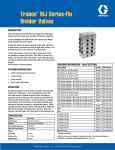
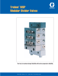
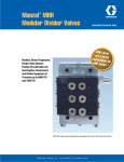
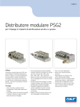
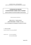
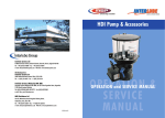
Trabon MX Series-Flo Dividers
®
DESCRIPTION
Trabon MX Series-Flo® Divider Valves are designed for heavy
service and are ideal for large steel mill systems and similar
applications. For modular version (MXP) having the same output
capacities, see bulletin 10132.
A typical MX Series-Flo® Divider Valve Assembly (to the right)
consists of an inlet section, end section and three to ten valve
sections. The basic divider assembly will serve between three and
twenty lube points.
The MX valve sections, which have built-in outlet check valves,
are available in various output per piston cycle sizes (see
specifications). Each twin (T) section has 2 outlets, one from each
side of the section. Each single (S) section has 1 outlet on either
side, but one outlet must be plugged to operate properly. For
applications with continuous oil lubrication (Meter-Flo) the built in
outlet check valves may be removed.
SPECIFICATION
Material
Plated Steel
Pressure (max)
3,000 psi (207 bar)
Lubricant
Oil or Grease
Max Operating Temperature
200ºF (93ºC)
Max Cycle Rate w/Cycle Pin
60 cycles/min.
MX w/o Cycle Pin
200 cycles/min.
Net Weight:
(Divider Valve Assembly approx.)
FEATURES/ADVANTAGES
• Delivers metered amount of lubricant.
• Economical and compact design.
3 Section DIvider
21 lbs, 6 oz (9.69 kg)
4 Section Divider
25 lbs, 10 oz (11.62 kg)
5 Section Divider
29 lbs, 14 oz (13.55 kg)
6 Section Divider
34 lbs, 2 oz (15.47 kg)
7 Section Divider
38 lbs, 6 oz (17.40 kg)
• Lubricant outlets easily added or removed.
8 Section Divider
42 lbs, 12 oz (19.39 kg)
• Simple to install on new or existing machines.
9 Section Divider
47 lbs, 2 oz (21.37 kg)
10 Section Divider
51 lbs, 8 oz (23.26 kg)
• Built-in outlet check valves.
• Hone-fitted metering pistons.
OPERATION
Operational sequence of an MX Series-Flo® Divider Valve
Assembly is defined as “progressive”. The term progressive
means that each valve section completes its piston stroke,
discharging a measured amount of lubricant to the bearing it
serves before the following valve section operates. As long as
lubricant is supplied under pressure to the inlet section of the
divider assembly, valve sections will continue to operate in a
progressive manner. Divider assemblies always follow a constant
discharge pattern. Whenever lubricant flow ceases, the valving
pistons will stop. When flow resumes it will start again at the
same point in the discharge cycle.
Torque:
Tie Rod Nut
23 ft lbs
Enclosure Plug
48 ft lbs
Outlet Port Plug
18 ft lbs
Sizes +
*cu.in.
cm3
25T
0.025
0.409
25S or 50T
0.050
0.819
50S or 100T
0.100
1.639
75T
0.075
1.229
75S or 150S
0.150
2.458
100S
0.200
3.278
125T
0.125
2.048
125S
0.250
4.097
150S
0.300
4.917
+ This number is stamped on each valve section
* This is the volume discharge per outlet after one complete cycle
DIMENSIONS
Inches/(mm)
ORDERING INFORMATION
MX -
X
-
XX
-
XXX
-
X
-
MANIFOLD
P - INSTALLATION OF PERFORMANCE
INDICATORS IN ALL WORKING OUTLETS
NUMBER OF SECTIONS
03 - THREE
04 - FOUR
05 - FIVE
06 - SIX
07 - SEVEN
08 - EIGHT
09 - NINE
10 - TEN
VALVE CAPACITY
025 - .025 cu.in. (SEE NOTE 8)
050 - .050 cu.in.
075 - .075 cu.in.
100 - .100 cu.in.
125 - .125 cu.in.
150 - .150 cu.in.
TYPE OF VALVE BLOCK
Note: Millimeter dimensions appear in parentheses below decimal figure in
inches.
No. of Sections
A-Dim.
B-Dim.
C-Dim
3
5.062 (128.57)
5.625 (142.87)
6.625 (168.27)
4
6.187 (157.14)
6.750 (171.45)
7.750 (196.85)
5
7.312 (185.72)
7.875 (200.02)
8.875 (225.42)
6
8.437 (214.29)
9.000 (228.60)
10.000 (254.00)
7
9.562 (242.87)
10.125 (257.17)
11.125 (282.57)
8
10.687 (271.44)
11.250 (285.75)
12.250 (311.15)
9
11.812 (300.02)
12.375 (314.90)
13.375 (339.72)
10
13.937 (328.59)
13.500 (342.90)
14.500 (368.30)
COMPONENT ORDERING
Description
Part No.
Old Part No.
Cycle Switch (SPDT) & Bracket
563272
510-599-000
Cycle Switch (DPDT) & Bracket
564357
510-577-000
Singling Bars
562916
189-000-060
Crossporting Bars
562917
189-000-090
Divider Installation Accessories
See Lit No. L15126
Performance Indicators
See Lit No. L15401
**Proximity Switch
See Lit No. L15600
Accessories & Parts
See Lit No. L10161
**Note: Date codes K95 and earlier use gasket type seals. Date codes
A96 and earlier late use o-ring seals. Verify type of seal used before
ordering a new or replacement proximity switch.
T - TWIN
S - SINGLE - RH OUTLET
L - SINGLE - LH OUTLET
B - TWIN W/CYCLE PIN RIGHT SIDE
C - SINGLE W/CYCLE PIN RIGHT SIDE - RH OUTLET
D - SINGLE W/CYCLE PIN RIGHT SIDE - LH OUTLET
H - TWIN W/CYCLE PIN LEFT SIDE
J - SINGLE W/CYCLE PIN LEFT SIDE - RH OUTLET
K - SINGLE W/CYCLE PIN LEFT SIDE - LH OUTLET
† CROSSPORTING OPTION
CR - RIGHT HAND SIDE
CL - LEFT HAND SIDE
CB - BOTH SIDES
† OMIT WHEN NOT REQUIRED
Divider Assembly Sketch Example
MX-5-50C-75T-100S-25SCR-100T
Divider With Indicator
NOTES:
1. Capacity sections are specified starting from inlet section, and must equal
number of sections specified.
2. When a capacity section is crossported, its outlet is plugged and output is
diverted to the next section, farthest from the inlet.
3. Last capacity section, farthest from the inlet, cannot be crossported.
4. Singled capacity sections can be crossported on one side only.
5. When capacity section is singled, the outlet not being used is plugged.
6. Internal crossporting can be supplied on a capacity section only when
supplied on a manifold assembly (if supplied as a loose unit, it can be field
drilled only).
7. External singling and crossporting bars are available for field installation.
8. Cycle Indicator Pin and Proximity Switch are not available on 0.025 capacity
section.
9. Indicate crossport option after capacity section if required, omit if not
required.
10. Divider systems should be limited to first and second stages only. Third
staging is not recommended. Refer to Trabon bulletins L20101, L20105, and
L20115 for further information on system design.
11. For information on the modular version (MXP) having the same output
capacities refer to Trabon bulletin L10132.
All written and visual data contained in this document are based on the latest product information available at the time of publication. Graco reserves the right to make changes at any time without notice.
Contact us today!
To receive product information or talk with a Graco representative,
call 800-533-9655 or visit us online at www.graco.com.
©2006-2009 Graco Inc. Form No. L10131 Rev. B 1/09 Printed in U.S.A. All other brand names or marks are used for identification purposes and are trademarks of their respective owners. All written and
visual data contained in this document are based on the latest product information available at the time of publication. Graco reserves the right to make changes at any time without notice.
XX