1
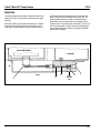
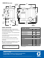
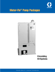
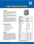
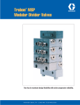
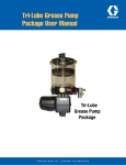
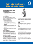
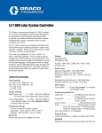
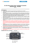
Maxi-Flo® Pump Package DESCRIPTION Designed for machinery requiring oil lubrication, this self-contained, easy-to-install package includes a reservoir, electric-motor-driven positive displacement pump, gear motor, and a choice of two control systems with a low-level switch as standard equipment. Optional accessories are a pressure gauge and a high pressure switch which, when used with MS or MJ series type divider valves, provide an economical means of effectively monitoring system operation. Note: Designing information for a Maxi-Flo system is available in Bulletin No. L23110. Compact Pump / Control Package for automatic, low-pressure, centralized oil lubrication systems. FEATURES / BENEFITS SPECIFICATIONS Pump Output per Stroke 0.010 in3 (0.165 cm3) Pump Output per min of OnTime 12 rpm @ 60 Hz 0.120 in3 (1.97 cm3) 10 rpm @ 50 Hz 0.100 in3 (1.64 cm3) Max System Operating Pressure 500 psi (34 bar) Atmosphere Relief Indicator Rating 600 psi (41 bar) Lubricant Oil, 60-30000 SUS • Choice of (1) Solid-State Time Control, or (2) Remote Control matches unit to application. • Easy installation. Just four mounting bolts and one electrical connection. • Transparent reservoir provides visual indication of oil level. • Manual run push-button simplifies line filling, system bleeding or purging, and/or testing system integrity. • Housing and reservoir are durable molded plastic. • Lights indicate low level, operating and power on. Standard Control Systems Time Control Operating Temperature Min 0ºF (-18ºC) Max - Intermittent Operation 140ºF (60ºC), 50% duty cycle or less) Reservoir Capacity 4 pints (1.9 liters), 116 in (1890 cm ) Pump Gearmotors 115V, 50/60 Hz, shaded pole, 12 rpm output @ 60 Hz, 10 rpm @ 50 Hz, 0.13 amp running current, 0.185 amp inrush current Reservoir Low Level Switch 3 115 VAC, 10 Watt Load NOTE: If the On-Time is set greater or equal to "Total Cycle Time" the timer will cause the pump to run continuously Remote Control Max - Continuous Operation 120ºF (49ºC) Solid State Timer, 115 VAC, 50/60 Hz, cycle time from 1/2 minute to 32 hours, adjustable On-Time of 12 sec to 13 minutes 3 115 VAC, 50/60 Hz, terminal strip for connection to machine control system Accessories Pressure Gauge 0-1000 psi (0-69 bar), back mount, 1/8 NPTF High Pressure Switch Factory set @ 550 psi (38 bar), 10 ampere contact rating @ 115 VAC Trabon® Maxi-Flo® Pump Package 13110 OPERATION The pump gearmotor, energized by one of the three control units, rotates an eccentric (A) connected to a rod that drives the pump piston (B). On the prime stroke, the piston opens the inlet port (C), allowing oil from the reservoir to flow into the piston chamber. On the power stroke, the piston motion closes the inlet port and forces the oil through the spring-loaded check valve (D) and the outlet port (E), and into the line to the divider valves. When "On", the pump gearmotor rotates the eccentric at a fixed speed of one pump strokes every 5 seconds on 60 hz, or one stroke every 6 seconds on 50 hz. The piston meters a fixed .010 in3 (0.16 cm3) of oil for every pump stroke. The total volume of oil delivered to the system is determined by the frequency and length of "ON TIME" that the pump is operated. MOTOR COMPARTMENT RESERVOIR ä ä ä OUTLET PORT FIGURE 1 A C B RELIEF INDICATOR PORT D E Page 2 Trabon® Maxi-Flo® Pump Package 13110 TOTAL CYCLE TIME Operation with Time Control TIME CONTROL ADJUSTMENTS Set the slide switch to either minutes or hours for cycle time. Next, set the desired pump "ON TIME" using a screwdriver in the slotted head of the scale marked "ON TIME MINUTES". Then in a similar fashion, set the specific interval at which lube cycles are to occur using the appropriate scale under "TOTAL CYCLE TIME". "ON TIME" in minutes = Total output required per cycle time (cu. in.) divided by 0.12 (60 hz) or 0.10 (50 hz) cu.in. per minute output rate. MINUTES HOURS 16 5 8 7 8 10 2 1 02 4 2 5 13 24 16 24 4 2 5 30 32 TOTAL CYCLE TIME MINUTES ON TIME MINUTES HOURS TIME CONTROL WIRING LOW LEVEL FAULT R When power is applied, the timer activates the lube pump motor and simultaneously begins timing of the "ON TIME" and "TOTAL CYCLE TIME". G A L2 L1 M 7 8 9 10 11 12 When the "ON TIME" is completed, the timer shuts off the pump motor but continues timing the "TOTAL CYCLE TIME" until the next cycle and "ON TIME". Activation of the manual run button resets the cycle time to zero and starts a lube cycle. The pump will stroke once every 5 seconds at 60 hz and once every 6 seconds at 50 hz of "ON TIME". MANUAL RUN 1 2 3 4 5 6 INPUT 115 /230 REMOTE CONTROL WIRING LOAD 3 AMPS NOT USED MAN RUN 7 8 9 10 11 12 FAULT L1 L2 Note: If the "ON TIME" is greater than the "TOTAL CYCLE TIME", the timer will cause the pump to run continuously. USER CONTROL Operation with Remote Control REMOTE CONTROL 1 2 3 4 This unit permits connection of the pump motor to the lubricated machine's control system, or to some other control system. M A The pump motor "ON TIME" will be determined by the machine or external system control. For most applications, it is recommended that the pump operate a minimum of one stroke per lubrication cycle. LOW LEVEL G REMOTE CONTROL R MANUAL RUN DETAIL ON STANDARD AND OPTIONAL SWITCHES HIGH PRESSURE SWITCH WIRING SINGLE POLE SINGLE THROW SW RATINGS - MAX RES. LOAD AMPS AMPS WATTS VOLTS AC DC 0-50 .2 0.05 10 120 .08 0.02 240 .04 N.A. A M 7 8 10 9 L1 L2 COMM. N.O. N.C. G LOW LEVEL HIGH PRESS SWITCH RESERVOIR COMPARTMENT ä MOTOR COMPARTMENT 11 12 R N.O. COMM. N.C. SINGLE POLE DOUBLE THROW 10 AMPS - 115/230 VAC 7 AMPS - 6-30 VDC LOW LEVEL SWITCH WIRE LEADS CONNECTED TO TERMINAL STRIP MANUAL RUN 1/8-27 NPSF (GAUGE PORT) ä ä ä ä ä ä STANDARD 600 PSI RELIEF INDICATOR OPTIONAL HIGH PRESSURE SWITCH Page 3 1 ä PUMP MOTOR COMPARTMENT ä NOTE: NONADJUSTABLE PRESSURE SWITCH FACTORY SET @ 550 PSI LUBE OUTLET 1/8-27 NPSF LOW LEVEL SWITCH SPST N.C. (Held Open) 2 RESERVOIR COMPARTMENT 3 4 5 1. When installing optional high pressure switch, remove factory jumper #4 to #11. 2. During normal operation, pressure switch N.C. contact is closed and pump motor will operate when timer calls for a lube cycle (red fault llight off). 6 7 8 3. High pressure condition causes switch contacts to transfer interrupting power to pump motor and applying power to red fault light and fault output (red fault light on). DIMENSIONS Inches (mm) ä FILL CAP ä ä ä ä 10.5 (265) ä 5.9 (150) FOR STANDARD 5/16 SCREWS 0.34 DIA. MTG. HOLES TYP. 4 PLACES ä 2.25 (57) 0.75 (19.1) Maxi-Flo Pump Package ä 1.75 (44.5) ä TRABON 6.44 (164) RED AMBER GREEN 9.5 (241) 3.56 (90.4) ä 0.84 DIA. HOLE FOR 1/2" CONDUIT FITTING TYP. 2 PLACES ä ä ä ä ä 0.62 (15.7) ä 10.625 (269.87) ä ä ä 6.44 (164) ä ä Maximum pump pressure is 500 psi. Damage may result if pump is operated in excess of 600 psi. Relief valve automatically relieves output to atmosphere at 600 psi. Fill reservoir with clean, filtered oil - never allow pump to operate on an empty reservoir. ä 11.375 (288.96) RELIEF INDICATOR (600 PSI) GENERAL INSTRUCTIONS LUBE OUTLET 1/8-27 NPSF ä MANUAL RUN BUTTON 2.28 (58) ⊄ ä RESERVOIR DRAIN PLUG ä SHOWN WITH OPTIONAL GAUGE COMPONENT ORDERING Description Part No. Old Part No. w/Time Control for 115 VAC, 50/60 Hz, Matched Pump Gearmotor 563379 521-500-910 w/Remote Control for 115 VAC, 50/60 Hz, Matched Pump Gearmotor 563376 521-500-430 Maxi-Flo Package To drain reservoir, remove the rubber plug at the bottom extreme right hand end of reservoir. *Optional Accessories High Pressure Switch 564376 521-500-330 Maxi-Flo pump should be cleaned with a mild detergent. Gauge (0-1000psi) 558899 493-020-241 Do not use more than 20 inch pounds of torque on the pump mounting bolts. Timer Replacement Board, 115 VAC 558031 572-142-590 Replacement 115 VAC Gearmotor 557641 521-500-650 Replacement Pump 563374 521-500-220 Replacement Low Level Switch 557826 541-603-002 Replacement Reservoir/Timer Housing Kit 563930 560-002-130 Replacement Relief Indicator 563375 521-500-400 Note: The Maxi-Flo package was not designed for use in outdoor applications. Do not install unit where it will be constantly exposed to direct sunlight and water. Graco endorses the SAE recommendation of ISO 18/14 (ISO 4406) oil cleanliness for most bearing applications. Some high speed bearing may require cleaner oil. Consult the bearing manufacturer for recommendation. Service Parts * Available for field installation only. Terminal strip supplied with high pressure option kit. All written and visual data contained in this document are based on the latest product information available at the time of publication. Graco reserves the right to make changes at any time without notice. Contact us today! To receive product information or talk with a Graco representative, call 800-533-9655 or visit us online at www.graco.com. ©2006-2009 Graco Inc. Form No. L13110 Rev. B 2/09 Printed in U.S.A. All other brand names or marks are used for identification purposes and are trademarks of their respective owners. All written and visual data contained in this document are based on the latest product information available at the time of publication. Graco reserves the right to make changes at any time without notice.