1
Instructions – Parts List
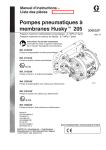
Huskyt 205 Air–Operated
Diaphragm Pumps
308652Y
ENG
100 psi (0.7 MPa, 7 bar) Maximum Incoming Air Pressure
100 psi (0.7 MPa, 7 bar) Maximum Fluid Working Pressure
Important Safety Instructions.
Read all warnings and instructions in this manual.
Save these instructions.
Part No. D120XX
Polypropylene Pump with Air–Operated Motor
Part No. D110XX and DM10XX
Acetal Pump with Air–Operated Motor
Part No. D150XX and DM50XX
PVDF Pump with Air–Operated Motor
Part No. D220XX
Polypropylene Pump with Solenoid Ports
Part No. D210XX
Acetal Pump with Solenoid Ports
ti10660a
Part No. D250XX
PVDF Pump with Solenoid Ports
Patent No.
CH ZL01113998.6
EU 0942171
US 5,860,794
AR AR006617B1
KP 461707
CH ZL01124998.6
BR PI9701779_5
Contents
Warnings . . . . . . . . . . . . . . . . . . . . . . . . . . . . . . . . . . . . . 2
Installation . . . . . . . . . . . . . . . . . . . . . . . . . . . . . . . . . . . . 4
Operation . . . . . . . . . . . . . . . . . . . . . . . . . . . . . . . . . . . . . 8
Maintenance . . . . . . . . . . . . . . . . . . . . . . . . . . . . . . . . . . . 9
Troubleshooting . . . . . . . . . . . . . . . . . . . . . . . . . . . . . . . 10
Service . . . . . . . . . . . . . . . . . . . . . . . . . . . . . . . . . . . . . . 12
Parts Matrix . . . . . . . . . . . . . . . . . . . . . . . . . . . . . . . . . . 15
Service Kit Matrix . . . . . . . . . . . . . . . . . . . . . . . . . . . . . 15
Parts Lists . . . . . . . . . . . . . . . . . . . . . . . . . . . . . . . . . . . . 16
Parts Drawing . . . . . . . . . . . . . . . . . . . . . . . . . . . . . . . . . 17
Torque Sequence . . . . . . . . . . . . . . . . . . . . . . . . . . . . . 18
Technical Data . . . . . . . . . . . . . . . . . . . . . . . . . . . . . . . . 19
Dimensions and Mounting Hole Layout . . . . . . . . . . . 20
Performance Charts . . . . . . . . . . . . . . . . . . . . . . . . . . . 21
Graco Standard Warranty . . . . . . . . . . . . . . . . . . . . . . 24
Graco Information . . . . . . . . . . . . . . . . . . . . . . . . . . . . . 24
Warning Symbol
WARNING
This symbol alerts you to the possibility of serious
injury or death if you do not follow the instructions.
Caution Symbol
CAUTION
This symbol alerts you to the possibility of damage to
or destruction of equipment if you do not follow the
instructions.
WARNING
EQUIPMENT MISUSE HAZARD
Any misuse of the equipment or accessories, such as overpressurizing, modifying parts, using
incompatible chemicals and fluids, or using worn or damaged parts, can cause them to rupture and
result in splashing in the eyes or on the skin, other serious injury, or fire, explosion or property damage.
D This equipment is for professional use only. Observe all warnings. Read and understand all
instruction manuals, warning labels, and tags before you operate this equipment. If you are not
sure, or if you have questions about installation or operation, call your Graco distributor.
D Never alter or modify any part of this equipment; doing so could cause it to malfunction. Use only
genuine Graco part numbers and accessories.
D Check all equipment regularly and repair or replace worn or damaged parts immediately.
D Never exceed the recommended working pressure or the maximum air inlet pressure stated on
your pump or in the Technical Data on page 19.
D Do not exceed the maximum working pressure of the lowest rated component in your system.
This equipment has a 100 psi (0.7 MPa, 7 bar) maximum working pressure at 100 psi
(0.7 MPa, 7 bar, ) maximum incoming air pressure.
D Be sure that all fluids and solvents used are chemically compatible with the wetted parts shown in
the Technical Data on page 19. Always read the manufacturer’s literature before you use fluid
or solvent in the pump.
D Never move or lift a pump under pressure. If dropped, the fluid section may rupture. Always
follow the Pressure Relief Procedure on page 8 before you move or lift the pump.
D Never use a polypropylene or PVDF pump with non-conductive flammable fluids as specified by
your local fire protection code. Refer to Grounding on page 4 for additional information. Consult
your fluid supplier to determine the conductivity or resistivity of your fluid.
2
D Provide fresh air ventilation to avoid the buildup of flammable fumes from solvents or the fluid
being pumped.
308652
WARNING
HAZARDOUS FLUIDS
Improper handling of hazardous fluids or inhaling toxic vapors can cause extremely serious injury or
death from splashing in the eyes, ingestion, or bodily contamination. Observe all the following
precautions when you handle hazardous or potentially hazardous fluids.
D Know what fluid you are pumping and its specific hazards. Take precautions to avoid a toxic fluid
spill.
D Always wear appropriate clothing and equipment, such as eye protection and breathing apparatus, to protect yourself.
D Store hazardous fluid in an appropriate, approved container. Dispose of it according to all Local,
State, and Federal guidelines for hazardous fluids.
D Secure the fluid outlet hose tightly into the receiving container to prevent it from coming loose
and improperly draining the fluid.
D Pipe and dispose of the exhaust air safely, away from people, animals, and food handling areas.
If the diaphragm fails, the fluid is exhausted along with the air. See Air Exhaust Ventilation on
page 5.
FIRE AND EXPLOSION HAZARD
Static electricity is created by the flow of fluid through the pump and hose. If the equipment is not
properly grounded, sparking may occur. Sparks can ignite fumes from solvents and the fluid being
pumped, dust particles, and other flammable substances, whether you are pumping indoors or
outdoors, and can cause a fire or explosion and serious injury and property damage.
D To reduce the risk of static sparking, ground the pump and all other equipment used or located in
the work area. Check your local electrical code for detailed grounding instructions for your area
and type of equipment. See Grounding on page 4.
D If you experience any static sparking or even a slight shock while using this equipment, stop
pumping immediately. Check the entire system for proper grounding. Do not use the system
again until you have identified and corrected the problem.
D Pipe and dispose of the exhaust air safely, away from all sources of ignition. If the diaphragm
fails, the fluid is exhausted along with the air. See Air Exhaust Ventilation on page 5.
D Do not smoke in the work area. Do not operate the equipment near a source of ignition or an
open flame, such as a pilot light.
United States Government safety standards have been adopted under the Occupational Safety and Health Act.
You should consult these standards—particularly the General Standards, Part 1910, and the Construction Standards, Part 1926.
308652
3
Installation
Tightening Threaded Fasteners Before
First Use
Before using the pump for the first time, check and
retorque all external fasteners. See Torque Sequence, page 18. After the first day of operation,
retorque the fasteners. Although pump use varies, a
general guideline is to retorque fasteners every two
months.
Use a compatible thread sealant on all male threads.
Tighten all connections firmly to avoid air or fluid leaks.
CAUTION
To avoid pump damage, do not overtighten the
fittings to the pump.
To reduce the risk of static sparking, ground the pump
and all other equipment used or located in the pumping
area. Check your local electrical code for detailed
grounding instructions for your area and type of equipment.
Acetal Pump Grounding Instructions
For polypropylene and PVDF pumps, see the
warning above.
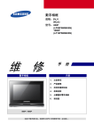
Ground all of this equipment.
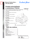
Pump: Connect a ground wire (A) and clamp, Part No.
222011. See Fig. 1. The pump grounding locations
are on the manifold between the inlet and outlet ports.
Use the nut (B) and bolt (C) that are provided with the
pump, and install as follows:
1. Place the nut in the nut catcher on the underside
of the manifold.
2. Insert the bolt through the loop end of the ground
wire.
3. Insert the bolt through the hole on the pump manifold and tighten it into the nut that you positioned
in step 1.
Grounding
4. Connect the clamp end of the ground wire to a
true earth ground.
WARNING
B
FIRE AND EXPLOSION HAZARD
This pump must be grounded. Before
you operate the pump, ground the
system as explained below. Also read
the section FIRE AND EXPLOSION
HAZARD on page 3.
grounding hole
C
The acetal pump contains stainless steel fibers
which make the wetted parts conductive. Attaching
the ground wire to one of the grounding locations
grounds the wetted parts.
The polypropylene and PVDF pumps are not
conductive. When you pump conductive flammable fluids, always ground the entire fluid system
by making sure the fluid has an electrical path to a
true earth ground. See Fig. 1. Never use a polypropylene or PVDF pump with non-conductive
flammable fluids as specified by your local fire
protection code. Consult your fluid supplier to
determine the conductivity or resistivity of your
fluid.
US Code (NFPA 77 Static Electricity) recommends
a conductivity greater than 50 x 10–12 Siemans/meter (mhos/meter) over your operating temperature
range to reduce the hazard of fire. Consult your
fluid supplier to determine the conductivity or
resistivity of your fluid. The resistivity must be less
than 2 x 10¹² ohm-centimeters.
4
308652
A
Fig.
Fig.11
06179A
D Air and fluid hoses: Use only grounded hoses with
a maximum of 500 ft (150 m) combined hose
length to ensure grounding continuity.
D Air compressor: Follow the manufacturer’s recommendations.
D All solvent pails used when flushing: Follow the
local code. Use only grounded metal pails, which
are conductive. Do not place the pail on a non-conductive surface, such as paper or cardboard, which
interrupts the grounding continuity.
D Fluid supply container: Follow the local code.
Installation
Air Exhaust Ventilation
.
WARNING
TOXIC FLUID HAZARD
Read the USING HAZARDOUS FLUIDS
and FIRE AND EXPLOSION HAZARD
sections on page 3 before you operate
this pump.
Be sure the system is properly ventilated
for your type of installation. You must
vent the exhaust to a safe place, away
from people, animals or food handling
areas when pumping flammable or
hazardous fluids.
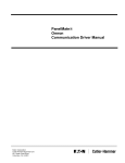
If the diaphragm ruptures, the fluid being pumped
is exhausted with the air. Place a container at the
end of the air exhaust line to catch fluid in case the
diaphragm ruptures, and disconnect the pump.
ti10662a
Fig. 2
D Be sure the mounting can support the weight of the
pump, hoses, and accessories, as well as the
stress caused during operation.
Mountings
CAUTION
The pump exhaust air may contain contaminants.
If needed, ventilate to a remote area to reduce
possible fluid contamination. See Air Exhaust
Ventilation on page 5.
D Mounting Bracket:
The pump is shipped with a 90 degree mounting
bracket (60). Mount the pump to the bracket using
the four screws (61) provided. Secure the opposite
portion of the mounting bracket to a horizontal
surface. The mounting bracket must be used for
proper pump performance.
D For all mountings, be sure the pump is secured with
screws and nuts.
WARNING
To reduce the risk of serious injury, splashing in
the eyes or on the skin, and toxic fluid spills,
never move or lift a pump under pressure. If
dropped, the fluid section may rupture. Always
follow the Pressure Relief Procedure on page
8 before you move or lift the pump.
308652
5
Installation
Air Lines
Fluid Lines
WARNING
Bleed-Type Master Air Valve and Fluid Drain
Valve
A bleed-type master air valve and a fluid drain
valve are required on your system.
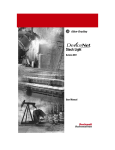
Fig. 3. On each end of the fluid manifold are a fluid IN
port and a fluid OUT port. NOTE: Make sure the fluid
OUT port on the fluid manifold is mounted up. This
will assure proper pump priming. Fluid-in and fluidout lines can be connected on the same end, or
opposite ends of the manifold. Plug ports that are not
used (plugs provided).
The bleed-type master air valve relieves air
trapped between itself and the pump. Trapped air
can cause the pump to cycle unexpectedly, which
could result in serious bodily injury, including
splashing in the eyes, injury from moving parts, or
contamination from hazardous fluids.
The fluid drain valve reduces the risk of serious
bodily injury, including splashing in the eyes or on
the skin, or contamination from hazardous fluids.
Install the fluid drain valve close to the pump’s
fluid outlet to relieve pressure in the hose if the
hose becomes plugged.
1. Mount the air line accessories on the wall or on a
bracket. Be sure the air line supplying the accessories is grounded.
a. The pump speed can be controlled in one of
two ways: To control it on the air side, install
an air regulator. To control it on the fluid side,
install a fluid valve near the outlet.
b. Install a bleed-type master air valve downstream from the air regulator, and use it to relieve trapped air. See the Bleed-Type Master
Air Valve and Fluid Drain Valve warning
above. Locate another bleed-type master air
valve upstream from all air line accessories,
and use it to isolate the accessories during
cleaning and repair.
c.
The air line filter removes harmful dirt and
moisture from the compressed air supply.
2. Install a flexible air hose between the accessories
and the pump air inlet. Screw the air line fitting
into the air inlet.
3. Do not restrict the exhaust port. Excessive exhaust restriction can cause erratic pump operation.
6
308652
ti10661a
Fig. 3
06179A
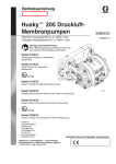
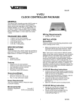
Typical Installation
The installations shown in Fig. 4 are only a guide to
help select and install a pump; they are not actual
system designs.
Typical installation includes (not supplied by Graco):
D For solenoid operation: a four-way, 5-port, 3-position solenoid valve with 1/4-in. ports, or two 3–position 3–way valves. Mac series 44 (4–way), or series
35 (3–way). Either way, air pressure should be
released if not cycling.
D PLC or timer. Consult your local industrial controls
distributor.
CAUTION
For solenoid operation, the pump must exhaust
through the solenoid. Failure to exhaust through
solenoid could cause the diaphragms to fail.
Installation
KEY
A
B
C
Husky 205 pump
Bleed-type master air valve
(required for pump)
Air line(s)
Master air valve (for accessories)
Air line filter
Muffler
Pump air regulator
Fluid drain valve
(required on fluid outlet side of pump)
Fluid suction line
Fluid supply hose
Bung adapter
4-way solenoid
Ground wire (required)
See page 4 for installation instructions.
C
E
F
G
H
J
L
N
T
U
Y
Air line to Port A
A
Y
N
L
J
Internal Air Valve View
(shown upright for clarity)
Air line to Port B
E
G
H
U
B C
F
Y
A
C
Remote Solenoid Operated
L
N
J
T
Remote Solenoid View
L
Air line to inlet
Internal Air Valve Operated
ti10663a
Fig. 4
308652
7
Operation
Pressure Relief Procedure
3. Place the suction tube (if used) in the fluid to be
pumped.
WARNING
To reduce the risk of serious injury, including
splashing fluid in the eyes or on the skin, follow this
procedure whenever you are instructed to relieve
pressure, when you shut off the pump, and before
you check, adjust, clean, move, or repair any
system equipment.
4. Place the end of the outlet hose into an appropriate container.
5. Close the fluid drain valve.
6. With the air regulator closed, open all bleed-type
master air valves.
1. Shut off air and reserve air to the pump.
2. Open the dispensing valve if the system has one.
3. Open the fluid drain valve to relieve all system
pressure, and have a container ready to catch the
drainage.
Flushing the Pump Before First Use
The pump was tested in water. If water could contaminate the fluid you are pumping, flush it thoroughly with
a compatible solvent. Follow the procedure in Starting and Adjusting the Pump.
7. If the outlet hose has a dispensing device, hold it
open while continuing with step 8.
8. Slowly open the air regulator until the pump starts
to cycle. Allow the pump to cycle until all air is
pushed out of the lines and the pump is primed.
NOTE: To prime a remote solenoid-operated
air valve, operate the pump at a minimum 60 cpm
rate until the pump is fully primed.
Starting and Adjusting the Pump
WARNING
To reduce the risk of serious injury, splashing in
the eyes or on the skin, and toxic fluid spills,
never move or lift a pump under pressure. If the
pump is dropped, the fluid section could rupture.
Always follow the Pressure Relief Procedure
above before you move or lift the pump.
1. Be sure the pump is properly grounded. Read and
follow the instructions in Grounding on page 4.
2. Check all fittings to be sure they are tight. Be sure
to use a compatible liquid thread sealant on all
male threads. Tighten the fluid inlet and outlet fittings and plugs securely. Retorque all fasteners
before start-up. See Torque Sequence, page 18.
8
308652
Pump Shutdown
At the end of the work shift, and before you check,
adjust, clean, or repair the system, relieve air and
fluid pressure.
WARNING
To reduce the risk of serious injury whenever you
are instructed to relieve pressure, always follow the
Pressure Relief Procedure at left.
Maintenance
Lubrication
Flushing and Storage
The air valve is lubricated at the factory and designed
to operate without additional lubrication.
If added lubrication is desired, every 500 hours of
operation (or monthly), remove the hose from the
pump air inlet and add two drops of machine oil to the
air inlet.
CAUTION
Do not over-lubricate the pump. Excess oil is
exhausted through the muffler, which could contaminate your fluid supply or other equipment.
Tightening Threaded Connections
Before each use, check all hoses for wear or damage,
and replace as necessary. Be sure all threaded connections are tight and free of leaks.
Check fasteners. Tighten or retorque as necessary.
Although pump use varies, a general guideline is to
retorque fasteners every two months. See Torque
Sequence, page 18.
Flush the pump to prevent the fluid from drying or
freezing in the pump and damaging it. Always flush
the pump and relieve the pressure before storing for
any length of time. Use a compatible solvent.
WARNING
To reduce the risk of serious injury whenever you
are instructed to relieve pressure, always follow the
Pressure Relief Procedure on page 8.
If you are flushing, run the pump long enough to
thoroughly clean the pump and hoses, close the air
regulator, and remove the suction hose from the
solvent and place it in the fluid to be pumped.
If you are shutting down the pump, remove the suction
hose from the fluid container, run the pump until the
fluid is forced out of the system, and shut off the air
supply immediately.
308652
9
Troubleshooting
Relieve the pressure before you check or service the
equipment.
Check all possible problems and causes before you
disassemble the pump.
WARNING
To reduce the risk of serious injury whenever you
are instructed to relieve pressure, always follow the
Pressure Relief Procedure on page 8.
Internal Air Valve-Operated and Remote Solenoid-Operated Pumps
PROBLEM
CAUSE
SOLUTION
The pump cycles at stall, or it fails
to hold pressure at stall.
The check valves (20) or o-rings
(21) are leaking.
Replace the check valves and/or
o-rings. See page 14.
The check valves (20) are worn.
Replace the check valves.
See page 14.
Debris is stuck between the a check Clean the check valve/seat area.
valve (20) and the seat.
See page 14.
The pump operates erratically.
The suction line is clogged.
Inspect and clear the line.
The check valves (20) are sticking
or leaking.
Replace the check valves, or clean
and check the valve/seat area.
See page 14.
A diaphragm (30) is ruptured.
Replace the ruptured diaphragm.
See page 13.
The suction line is loose.
Tighten the suction line.
A diaphragm (30) is ruptured.
Replace the ruptured diaphragm.
See page 13.
The manifold (52) is loose, or the
o-rings (21) are damaged.
Tighten the manifold screws (58).
Replace the o-rings (21).
See page 14.
The fluid covers (51) are loose.
Tighten the fluid cover screws (58).
See page13.
A diaphragm (30) is ruptured.
Replace the ruptured diaphragm.
See page 13.
A diaphragm plate (50) is loose.
Tighten the diaphragm plate.
See page13.
The pump exhausts air near the
fluid covers.
The fluid covers (51) are loose, or
the o-rings (57) are damaged.
Tighten the fluid cover screws (58),
or replace the o-rings. See page13.
The pump exhausts air near the air
valve.
The air valve cover screws (14) are
loose.
Tighten the screws. See page 12.
The top (5) and/or side (6) air valve
o-rings are damaged.
Replace these o-rings.
See the Parts Drawing on
page 17.
The o-rings (21) are leaking, or the
screws (58) are loose.
Replace these o-rings, and tighten
the screws. See page 14.
There are air bubbles in the fluid.
There is fluid in the exhaust air.
The pump leaks fluid from the
check valves.
10
308652
Troubleshooting
Internal Air Valve-Operated Pumps Only
PROBLEM
CAUSE
SOLUTION
The pump will not cycle, or it cycles
once and stops.
The air valve is stuck or dirty.
Disassemble and clean or repair the
air valve. See page 12.
Use filtered air.
Not enough air pressure supplied.
Increase air pressure supply. Do not
exceed maximum input pressure.
Remote Solenoid-Operated Pumps Only
PROBLEM
CAUSE
SOLUTION
The pump will not prime or loses
prime.
The cycle rate is too low.
Increase cycle rate to 60 cpm.
The check valves (20) are not Inspect the check valves, and
sealing.
replace them if worn or damaged.
See page 14.
Fluid manifold not mounted with OUT Re-mount fluid manifold so OUT
port up.
port is up.
The pump leaks air or does not
operate.
Air is supplied to Port A and Port B
at the same time.
Replace both diaphragms (30).
See page 13.
Check your installation. See
page 7.
Solenoid exhaust is plugged.
Ensure that exhaust (G on page 7)
is free of obstructions.
308652
11
Service
2. Remove the four screws (14) that hold the valve
cover (7) on the center housing (1).
Service Kits
Service Kits may be ordered separately.
To repair the air valve, order Part No. 238853. Parts
included in the Air Valve Service Kit are marked with
an asterisk in the Parts Drawing on page 17, for
example (3*).
For fluid section repair section parts, see the Service
Kit Matrix on page 15. Parts included in the Fluid
Section Service Kit are marked with a dagger in the
Parts Drawing on page 17, for example (4{).
Servicing the Air Valve
3. Remove the valve block (4) and valve carriage (2),
and replace the u-cups (3). Replace the valve
carriage and valve block. When you replace the
valve carriage, position it all the way to one side or
the other.
NOTE: The valve block shown in Fig. 5 is for
pumps with an air-operated air motor. If your
pump has a solenoid-operated air motor, this step
does not pertain. Items 2, 3, 4, 16, and 17 are not
required.
4. Clean any parts that are dirty.
Service the air valve as follows. See Fig. 5.
1. Relieve the fluid pressure, and disconnect air
line from the pump.
WARNING
To reduce the risk of serious injury whenever you
are instructed to relieve pressure, always follow the
Pressure Relief Procedure on page 8.
5. To reinstall the valve cover (7), spread cover apart
enough not to damage the square ring packings
(6) and slide cover (7) into the center section.
6. Install the screws (14), and torque to 40 to 45 in-lb
(4.5 to 5.0 NSm). See Torque Sequence on page
18.
7. Reconnect the pump.
1
Lips of u-cups (3) must face toward each other
(toward center of valve carriage (2)).
6
14
17
16
4
7
1
1
3
2
1
6
Fig. 5
12
3
308652
ti10664a
Service
Replacing Diaphragms
Replace the diaphragms as follows. See Fig. 6 and Fig 7.
1. Relieve the pressure, and disconnect the air line
from the pump.
5. Remove the diaphragm pins (8), remove and
replace the o-rings (9), and reinstall the diaphragm
pins in the center housing (1).
WARNING
6. Reinstall the diaphragm shaft (10).
7. Install the new diaphragms (30) with the concave
side toward the center housing (1).
To reduce the risk of serious injury whenever you
are instructed to relieve pressure, always follow the
Pressure Relief Procedure on page 8.
8. Screw the diaphragm plates (50) onto the shaft
(10), and torque to 28–33 in-lb (3.2–3.7 NSm).
9. Reinstall the fluid covers (51) on the center housing (1), install the screws (58) that fasten the fluid
covers to the center housing, and torque to 42–47
in-lb (4.7–5.3 NSm). See Torque Sequence on
page 18.
2. Remove the eight screws (58) that fasten the two
fluid covers (51) to manifold (52), and remove the
fluid cover/center housing assembly from the
manifold.
3. Remove the six screws (58) that fasten each fluid
cover (51) to the center housing (1), and pull the
fluid covers off of the center housing.
10. Reinstall the fluid covers/center housing assembly
on the manifold (52), install the screws (58) that
fasten the fluid covers/center housing assembly to
the manifold, and torque to 42–47 in-lb (4.7–5.3
NSm). See Torque Sequence on page 18.
4. Remove the diaphragm plates (50) from the shaft
(10), and remove the diaphragms (30), and airside diaphragm plates (11).
11. Reconnect the pump.
9
8
1
12
13
10
11
58
57
30
50
51
58
06180D
Fig. 6
308652
13
Service
Replacing Check Valves
Replace each pair of check valves as follows. See
Fig. 7.
1. Relieve the pressure, and disconnect the air line
from the pump.
3. Remove and replace the check valves (20), being
careful to orient each check valve exactly like
the one it is replacing. Make sure the check
valve/seat area is clean.
4. Remove and replace the sealing o-rings (21).
Once compressed, o-rings may not be reused.
Make sure the check valve/seat area is clean.
WARNING
To reduce the risk of serious injury whenever you
are instructed to relieve pressure, always follow the
Pressure Relief Procedure on page 8.
2. Remove the eight screws (58) that hold the fluid
cover/center housing assembly on the manifold (52), and lift the manifold covers/center housing assembly off of the manifold (52).
5. Reinstall the fluid covers/center housing assembly
on the manifold (52), install the screws (58) that
fasten the fluid covers/center housing assembly to
the manifold, and torque to 42–47 in-lb (4.5–5.0
NSm). See Torque Sequence on page 18.
6. Reconnect the pump.
52
58
21
20
1
51
58
ti10665a
Fig. 7
14
308652
Parts Matrix
Husky 205 Polypropylene, Acetal*, and PVDF Pumps
The Model Number of your pump is marked on the pump’s serial plate. To determine the Model Number of your
pump from the following matrix, select the six digits that describe your pump, working from left to right. The first
digit is always D, designating Husky diaphragm pumps. The remaining five digits define the materials of
construction. For example, a pump with a Husky 205 polypropylene air motor, polypropylene fluid section,
polypropylene check valves, and PTFE diaphragms is Model D 1 2 0 9 1. To order replacement parts, refer to
the Part Lists on pages 16 and 17. The digits in the matrix do not correspond to the reference numbers in text,
Parts Drawings, or Parts Lists.
Diaphragm
Pump
Air Motor
Fluid Section
Seats and Guides
Checks
Diaphragms
D (for all pumps)
1 (Husky 205;
polypropylene,
standard)
1 (acetal)*
0 (no seats/guides)
2 (Husky 205;
polypropylene,
for solenoid
operation)
2 (acetal)
1 (PTFE)
2 (polypropylene)
A (PVDF)
6 (SantopreneR)
3 (not used)
9 (polypropylene)
4 (not used)
5 (PVDF)
M (Husky 205;
polypropylene,
standard with
fluoroelastomer
o–rings on actuator pin)
*
Note: Model 24E366 uses the same parts as D11021. The pump is
packaged and sold as PN 24J001.
II 2 G Certified
Service Kit Matrix
Air Valve and Fluid Section Service Kits for Husky 205 Pumps
To determine the Model Number of your service kit from the following matrix, select the six digits that describe your
pump, working from left to right. The first digit is always D, designating Husky diaphragm pumps. The second digit
is always 0 (zero), and the third digit is always 1 (one). The remaining five digits define the materials of
construction. For example, if your pump has polypropylene checks and PTFE diaphragms, order Repair Kit
D 0 1 0 9 1. If you only need to repair certain parts (for example, the diaphragms), use the 0 (null) digit for the
balls, and order Repair Kit D 0 1 0 0 1. To order replacement parts, refer to the Part Lists on pages16 and 17.
The digits in the matrix do not correspond to the reference numbers in text, Parts Drawings, or Parts Lists.
Diaphragm
Pump
Air Motor
O-rings
Seats
Checks
Diaphragms
D (for all pumps
except DMXXXX)
0 (for all pumps
except DMXXXX)
1 (for all pumps
except DMXXXX)
0 (for all pumps
except DMXXXX)
0 (null)
0 (null)
A (PVDF)
1 (PTFE)
2 (acetal)
6 (SantopreneR)
9 (polypropylene)
308652
15
Parts
Air Motor Section (matrix column 2)
Ref.
Digit No.
Part No.
Description
Qty.
1
240898
HOUSING, center,
assembly (includes 12,
13, and 57)
1
2
1
290229
LABEL, warning
1
50
191553
PLATE, diaphragm;
acetal
2
51
276474
COVER, fluid; acetal
2
52
276471
MANIFOLD; acetal
1
2
191157
CARRIAGE, valve
1
53
113576
PLUG, port; acetal
2
3
113869
SEAL, u-cup
2
54
100264
SCREW, grounding
2
4
194533
VALVE BLOCK (for
pump with air-operated
air motor)
1
55
100179
NUT, hex , grounding
2
57
113570
O-RING, packing
2
58
113341
SCREW, torx
20
59
115055
O-RING, exhaust
1
60
194986
BRACKET, mounting
1
61
111630
SCREW, machine, pn hd
4
7
191140
COVER, valve
1
49
290229
LABEL, warning
1
50
191141
2
51
276473
PLATE, diaphragm;
polypropylene
COVER, fluid;
polypropylene
MANIFOLD;
polypropylene
5
191160
GASKET, molded
1
6
115056
O-RING, packing
2
8
191021
PIN, actuator
2
9
113565
O-RING, packing
2
103557
O-RING, packing
(DMXXXX pumps only)
2
2
10
193778
SHAFT, diaphragm
1
11
193775
PLATE, diaphragm, air
side
2
12
114710
O-RING, diaphragm
shaft
2
52
276470
13
15J176
BEARING, retaining
2
53
113577
PLUG, port;
polypropylene
2
14
113341
SCREW, torx
4
57
113570
O-RING, packing
2
15
114174
MUFFLER, porous
plastic
1
58
113341
SCREW, torx
20
16
194386
SEAL, valve plate
1
59
115055
O-RING, exhaust
1
17
194384
PLATE, valve
1
60
194986
BRACKET, mounting
1
1
240899
HOUSING, center,
assembly (includes 12,
13, and 57)
1
61
111630
SCREW, machine, pn hd
4
7
191140
COVER, valve
1
49
290229
LABEL, warning
1
50
191554
PLATE, diaphragm;
PVDF
2
51
276475
COVER, fluid; PVDF
2
52
276472
MANIFOLD; PVDF
1
5
2
1
10
193778
SHAFT, diaphragm
1
11
193775
PLATE, diaphragm, air
side
1
12
114710
O-RING, diaphragm
shaft
2
13
15J176
BEARING, retaining
2
53
113447
PLUG, port; PVDF
2
14
113341
SCREW, torx
4
57
113570
O-RING, packing
2
15
114174
MUFFLER, porous
plastic
1
58
113341
SCREW, torx
20
59
111137
O-RING, exhaust
1
60
194986
BRACKET, mounting
1
61
111630
SCREW, machine, pn hd
4
Fluid Section (matrix column 3)
Ref.
Digit No.
Part No.
Description
Qty.
1
191140
COVER, valve
1
16
49
7
308652
Parts
Check Valve (matrix column 5)
Diaphragm (matrix column 6)
Digit Ref.
Part No.
Description
Qty.
Digit Ref.
Part No.
Description
Qty.
2
20
241134
VALVE, check; acetal
4
1
30
191402
2
21
113566
O-RING, packing
4
DIAPHRAGM; PTFE
(for all Husky 205
pumps)
20
240896
VALVE, check;
polypropylene
4
6
30
196385
DIAPHRAGM;
SantopreneR
2
21
113566
O-RING, packing
4
20
240897
VALVE, check; PVDF
4
21
113566
O-RING, packing
4
9
A
52
58
60
61
6
51
21{ 59{
50
7
6}* 20
30
57{
11
55
3
14
*}16
*}17
*}4
54
12{
1
13{
10
7
11
57
53
30
50
1
5
9
7
9{
4
*H}3
8
15
5}*
*H}2
4
*H}3
*} 6
H
*
{
}
1
Used on acetal models only.
3
Torque to 40–45 in-lb (4.5–5.0 NSm). See Torque Sequence on page 18
4
Lips of u–cups (3) must face toward each other, toward center of valve carriage (2).
5
Torque to 20 in-lb (2.2 NSm).
6
Torque to 42–47 in–lb (4.7–5.3 NSm). See Torque Sequence on page 18.
7
Torque to 28–33 in–lb (3.2–3.7 NSm). See Torque Sequence on page 18.
9
Not assembled. These plugs are supplied to plug the two ports in the manifold that are not used.
51
6
58
ti10666a
These parts cannot be ordered separately. They come preassembled and are included as part of the Air Valve Service Kit 238853.
These parts are included in Air Valve Service Kit 238853, which may be purchased separately.
These parts are included in Fluid Section Service Kit. D010xx, which may be purchased separately.
These parts are included in pump with integral air valve only.
308652
17
Torque Sequence
For proper installation, always follow torque sequence
whenever you are instructed to torque screws.
1. Valve Cover
2. Left/Right Fluid Cover
Torque bolts to 40–45 in–lb (4.5–5.0 NSm)
3
1
2
Torque bolts to 42–47 in–lb (4.7–5.3 NSm)
8
10
6
5
9
7
4
3. Manifold to Center Section
Torque bolts to 42–47 in–lb (4.7–5.3 NSm)
16
17
11, 19
12, 20
13
14
15
18
Back View
18
308652
Front View
Technical Data
Maximum fluid working pressure . . . . . . . . . . . . . 100 psi
(0.7 MPa, 7 bar)
Maximum/minimum air pressure . . . . . . 100 psi/20psi
(0.7 MPa, 7 bar)/(0.14 MPa, 1.4 bar)
Maximum fluid flow . . . . . . . . . . . . . 5.0 gpm (18.9 lpm)
Maximum pump speed . . . . 320(dry) cycles per minute
250(wet) cycles per minute
Volume per stroke* . . . . . . . . . . . . . . . 0.006 gal (23 cc)
Volume per cycle* . . . . . . . . . . . . . . . . 0.012 gal (46 cc)
Maximum suction lift dry . . . . . . . . . . . . . . . . . . 8 to 10 ft
(2.5 to 3 m)
Maximum size pumpable solids . . . . 0.06 in. (1.5 mm)
Maximum operating temperature . . . . . 180_ F (82_ C)
Maximum air consumption . . . . . . . . . . . . . . . 9.0 scfm
(0.252 m3/min.)
Air inlet size** . . . . . . . . . . . . . . . . . 1/4 npt(f) / 1/4 bsp(f)
Fluid inlet size** . . . . . . . . . . . . . . . 1/4 npt(f) / 1/4 bsp(f)
Fluid outlet size** . . . . . . . . . . . . . . 1/4 npt(f) / 1/4 bsp(f)
Air exhaust port size** . . . . . . . . . 1/4 npt(f) / 1/4 bsp(f)
Weight
Polypropylene pump . . . . . . . . . . . . . . . 2.0 lb (0.9 kg)
Acetal pump . . . . . . . . . . . . . . . . . . . . . . 2.5 lb (1.1 kg)
PVDF pump . . . . . . . . . . . . . . . . . . . . . . 2.8 lb (1.3 kg)
Wetted parts (housings, diaphragms, check valves)
Polypropylene pump:
Glass-filled polypropylene, PTFE, polypropylene
Acetal pump:
Acetal with SST fibers, PTFE, acetal
PVDF pump:
PVDF, PTFE, PVDF
Sound power level (pressure) (per ANSI STD S12.1)
at 100 psi (0.7 MPa, 7 bar) . . . . . . . . . . . . . 75.5 dBa
at 70 psi (0.49 MPa, 4.9 bar) . . . . . . . . . . . . 72.0 dBa
at 40 psi (0.28 MPa, 2.8 bar) . . . . . . . . . . . . 68.2 dBa
Sound power level (intensity) (per ANSI STD S12.1)
at 100 psi (0.7 MPa, 7 bar) . . . . . . . . . . . . . 84.5 dBa
at 70 psi (0.49 MPa, 4.9 bar) . . . . . . . . . . . . 81.1 dBa
at 40 psi (0.28 MPa, 2.8 bar) . . . . . . . . . . . . 76.6 dBa
* Volume per cycle may vary based on suction condition, discharge head, air pressure, and fluid.
** Hybrid thread allows for either 1/4 npt or 1/4 bsp fitting.
PVDF is a registered trademark of Atochem North America, Incorporated.
Schrader Bellowsr is a registered trademark of Schrader Bellows.
Santoprener is a registered trademark of the Monsanto Company.
308652
19
Dimensions and Mounting Hole Layout
6.0 in.
152.4 mm
3.7 in.
94 mm
5.4 in.
137 mm
Four 0.175 in. x .85 in. deep
4.445 mm x 21.59 mm deep
diameter holes
ti10913a
3.0 in.
76.2 mm
Four 0.281 in.
7.137 mm
diameter holes
2.5 in.
63.5 mm
Four 0.230 in. (5.8 mm)
diameter holes
6.8 in.
173 mm
ti10914a
20
308652
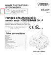
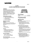
Performance Charts
Husky 205 Fluid Outlet Pressure
Test Conditions: Pump tested in water with inlet submerged.
FLUID OUTLET PRESSURE––psi (MPa, bar)
100
(0.7, 7)
90
(0.62, 6.2)
Fluid Pressure Curves
80
(0.55, 5.5)
A at 100 psi (0.7 MPa, 7 bar) air pressure
B at 70 psi (0.48 MPa, 4.8 bar) air pressure
C at 40 psi (0.28 MPa, 2.8 bar) air pressure
70
(0.48, 4.8)
60
(0.41, 4.1)
50
(0.35, 3.5)
A
40
(0.28, 2.8)
B
30
(0.21, 2.1)
C
20
(0.14, 1.4)
10
(0.07, 0.7)
0
0
0.5
(1.9)
1
(3.8)
1.5
(5.7)
2
(7.6)
2.5
(9.5)
3
(11.4)
3.5
(13.3)
FLUID FLOW--gpm (lpm)
To find Fluid Outlet Pressure (psi/MPa/bar) at a
specific fluid flow (gpm/lpm) and operating air
pressure (psi/MPa/bar):
1. Locate fluid flow rate along bottom of chart.
2. Follow vertical line up to intersection with selected
fluid outlet pressure curve.
3. Follow left to scale to read fluid outlet pressure.
308652
21
Performance Charts
Husky 205 Air Consumption
Test Conditions: Pump tested in water with inlet submerged.
6
(0.17)
AIR CONSUMPTION––scfm (cubic meters/min)
A
5
(0.14)
Air Consumption Curves
A at 100 psi (0.7 MPa, 7 bar) air pressure
B at 70 psi (0.48 MPa, 4.8 bar) air pressure
C at 40 psi (0.28 MPa, 2.8 bar) air pressure
4
(0.11)
B
3
(0.09)
2
(0.06)
C
1
(0.03)
0
0
0.5
(1.9)
1
(3.8)
1.5
(5.7)
2
(7.6)
2.5
(9.5)
FLUID FLOW--gpm (lpm)
To find Pump Air Consumption (scfm or m#/min) at a
specific fluid flow (gpm/lpm) and air pressure
(psi/MPa/bar):
1. Locate fluid flow rate along bottom of chart.
2. Read vertical line up to intersection with selected air
consumption curve.
3. Follow left to scale to read air consumption.
22
308652
3
(11.4)
3.5
(13.3)
Notes
308652
23
Graco Warranties
Graco Standard Husky Pump Warranty
Graco warrants all equipment manufactured by Graco and bearing its name to be free from defects in material and workmanship on the
date of sale to the original purchaser for use. With the exception of any special, extended, or limited warranty published by Graco,
Graco will, for a period of five years from the date of sale, repair or replace any part of the equipment determined by Graco to be
defective. This warranty applies only when the equipment is installed, operated and maintained in accordance with Graco’s written
recommendations.
This warranty does not cover, and Graco shall not be liable for general wear and tear, or any malfunction, damage or wear caused by
faulty installation, misapplication, abrasion, corrosion, inadequate or improper maintenance, negligence, accident, tampering, or substitution of non-Graco component parts. Nor shall Graco be liable for malfunction, damage or wear caused by the incompatibility of
Graco equipment with structures, accessories, equipment or materials not supplied by Graco, or the improper design, manufacture,
installation, operation or maintenance of structures, accessories, equipment or materials not supplied by Graco.
This warranty is conditioned upon the prepaid return of the equipment claimed to be defective to an authorized Graco distributor for
verification of the claimed defect. If the claimed defect is verified, Graco will repair or replace free of charge any defective parts. The
equipment will be returned to the original purchaser transportation prepaid. If inspection of the equipment does not disclose any defect
in material or workmanship, repairs will be made at a reasonable charge, which charges may include the costs of parts, labor, and
transportation.
THIS WARRANTY IS EXCLUSIVE, AND IS IN LIEU OF ANY OTHER WARRANTIES, EXPRESS OR IMPLIED, INCLUDING BUT
NOT LIMITED TO WARRANTY OF MERCHANTABILITY OR WARRANTY OF FITNESS FOR A PARTICULAR PURPOSE.
Graco’s sole obligation and buyer’s sole remedy for any breach of warranty shall be as set forth above. The buyer agrees that no other
remedy (including, but not limited to, incidental or consequential damages for lost profits, lost sales, injury to person or property, or any
other incidental or consequential loss) shall be available. Any action for breach of warranty must be brought within six years of the date
of sale.
Graco makes no warranty, and disclaims all implied warranties of merchantability and fitness for a particular purpose in connection
with accessories, equipment, materials or components sold but not manufactured by Graco. These items sold, but not manufactured
by Graco (such as electric motors, switches, hose, etc.), are subject to the warranty, if any, of their manufacturer. Graco will provide
purchaser with reasonable assistance in making any claim for breach of these warranties.
In no event will Graco be liable for indirect, incidental, special or consequential damages resulting from Graco supplying equipment
hereunder, or the furnishing, performance, or use of any products or other goods sold hereto, whether due to a breach of contract,
breach of warranty, the negligence of Graco, or otherwise.
FOR GRACO CANADA CUSTOMERS
The parties acknowledge that they have required that the present document, as well as all documents, notices and legal proceedings
entered into, given or instituted pursuant hereto or relating directly or indirectly hereto, be drawn up in English. Les parties reconnaissent avoir convenu que la rédaction du présente document sera en Anglais, ainsi que tous documents, avis et procédures judiciaires
exécutés, donnés ou intentés à la suite de ou en rapport, directement ou indirectement, avec les procedures concernées.
Extended Product Warranty
Graco warrants all Husky 205, 307, 515, 716, 1040, 1590, 2150, and 3275 air valve center sections to be free from defects in material
and workmanship for a period of fifteen years from date installed in service by the original purchaser. Normal wear of items such as
packings or seals are not considered to be defects in material and workmanship.
Five years
Six to Fifteen years
Graco will provide parts and labor.
Graco will replace defective parts only.
Graco Information
TO PLACE AN ORDER, contact your Graco distributor, or call one of the following numbers
to identify the distributor closest to you: 1–800–328–0211 Toll Free, 612–623–6921, 612–378–3505 Fax
All written and visual data contained in this document reflects the latest product information available at the time of publication.
Graco reserves the right to make changes at any time without notice.
Original instructions. This manual contains English. MM 308652
Graco Headquarters: Minneapolis
International Offices: Belgium, China, Japan, Korea
GRACO INC.ąP.O. BOX 1441ąMINNEAPOLIS, MNą55440-1441
Copyright 1996, Graco Inc. is registered to ISO 9001
www.graco.com
Revised 4/2011
24
308652