1
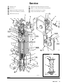
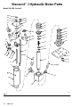
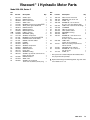
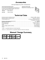
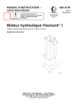
INSTRUCTIONS-PARTS LIST
This manual contains important
warnings and information.
READ AND KEEP FOR REFERENCE.
308–618
First choice when
quality counts.
Rev. C
Supersedes Rev. B
INSTRUCTIONS
Viscount I Hydraulic Motor
1500 psi (10 MPa, 102 bar) Maximum Hydraulic Input Pressure
Model 238–356, Series C
06168
GRACO INC.
P.O. BOX 1441 MINNEAPOLIS, MN
http://www.graco.com
COPYRIGHT 1996, GRACO INC.
Graco Inc. is registered to I.S. EN ISO 9001
55440–1441
Table of Contents
Warnings . . . . . . . . . . . . . . . . . . . . . . . . . . . . . . . . . . . . . . 2
Installation . . . . . . . . . . . . . . . . . . . . . . . . . . . . . . . . . . . . 5
Operation . . . . . . . . . . . . . . . . . . . . . . . . . . . . . . . . . . . . . 6
Troubleshooting . . . . . . . . . . . . . . . . . . . . . . . . . . . . . . . . 7
Service . . . . . . . . . . . . . . . . . . . . . . . . . . . . . . . . . . . . . . . 7
Required Tools . . . . . . . . . . . . . . . . . . . . . . . . . . . . . 7
Hydraulic Motor Disassembly . . . . . . . . . . . . . . . . 8
Hydraulic Motor Reassembly . . . . . . . . . . . . . . . . 10
Parts Drawing and Parts List . . . . . . . . . . . . . . . . . . . .
Accessories . . . . . . . . . . . . . . . . . . . . . . . . . . . . . . . . . .
Technical Data . . . . . . . . . . . . . . . . . . . . . . . . . . . . . . . .
Graco Standard Warranty . . . . . . . . . . . . . . . . . . . . . .
Graco Phone Number . . . . . . . . . . . . . . . . . . . . . . . . . .
12
14
14
16
16
Symbols
Warning Symbol
Caution Symbol
WARNING
CAUTION
This symbol alerts you to the possibility of serious
injury or death if you do not follow the instructions.
This symbol alerts you to the possibility of damage to
or destruction of equipment if you do not follow the
instructions.
WARNING
EQUIPMENT MISUSE HAZARD
Equipment misuse can cause the equipment to rupture or malfunction and result in serious injury.
This equipment is for professional use only.
Read all instruction manuals, tags, and labels before operating the equipment.
Use the equipment only for its intended purpose. If you are not sure, call your Graco distributor.
Do not alter or modify this equipment. Use only genuine Graco parts and accessories.
Check equipment daily. Repair or replace worn or damaged parts immediately.
Do not exceed the maximum working pressure stated on the equipment or in the Technical Data
for your equipment. Do not exceed the maximum working pressure of the lowest rated component
in your system.
Use fluids and solvents which are compatible with the equipment wetted parts. Refer to the Technical Data section of all equipment manuals. Read the fluid and solvent manufacturer’s warnings.
Handle hoses carefully. Do not pull on hoses to move equipment.
Route hoses away from traffic areas, sharp edges, moving parts, and hot surfaces. Do not expose
Graco hoses to temperatures above 66C (150F) or below –40C (–40F).
Wear hearing protection when operating this equipment.
Do not move or lift pressurized equipment.
Comply with all applicable local, state, and national fire, electrical, and safety regulations.
WARNING
INJECTION HAZARD
Spray from the gun, leaks or ruptured components can inject fluid into your body and cause extremely
serious injury, including the need for amputation. Fluid splashed in the eyes or on the skin can also
cause serious injury.
Fluid injected into the skin is a serious injury. The injury may look like just a cut, but it is a serious
injury. Get immediate medical attention.
Do not point the gun at anyone or at any part of the body.
Do not put your hand or fingers over the spray tip.
Do not stop or deflect leaks with your hand, body, glove or rag.
Do not “blow back” fluid; this is not an air spray system.
Always have the tip guard and the trigger guard on the gun when spraying.
Check the gun diffuser operation weekly. Refer to the gun manual.
Be sure the gun trigger safety operates before spraying.
Lock the gun trigger safety when you stop spraying.
Follow the Pressure Relief Procedure on page 6 if the spray tip clogs and before cleaning,
checking or servicing the equipment.
Tighten all fluid connections before operating the equipment.
Check the hoses, tubes, and couplings daily. Replace worn or damaged parts immediately. Do not
repair high pressure couplings; you must replace the entire hose.
Fluid hoses must have spring guards on both ends, to help protect them from rupture caused by
kinks or bends near the couplings.
MOVING PARTS HAZARD
Moving parts can pinch or amputate your fingers.
Keep clear of all moving parts when starting or operating the pump.
Before checking or servicing the equipment, follow the Pressure Relief Procedure on page 6 to
prevent the equipment from starting unexpectedly.
WARNING
FIRE AND EXPLOSION HAZARD
Improper grounding, poor ventilation, open flames or sparks can cause a hazardous condition and result in a fire or explosion and serious injury.
Ground the equipment and the object being sprayed. Refer to Grounding on page 5.
If there is any static sparking or you feel an electric shock while using this equipment, stop spraying immediately. Do not use the equipment until you identify and correct the problem.
Provide fresh air ventilation to avoid the buildup of flammable fumes from solvents or the fluid
being sprayed.
Keep the spray area free of debris, including solvent, rags, and gasoline.
Before operating this equipment, electrically disconnect all equipment in the spray area.
Before operating this equipment, extinguish all open flames or pilot lights in the spray area.
Do not smoke in the spray area.
Do not turn on or off any light switch in the spray area while spraying or while operating if fumes
are present.
Do not operate a gasoline engine in the spray area.
TOXIC FLUID HAZARD
Hazardous fluid or toxic fumes can cause serious injury or death if splashed in the eyes or on the skin,
inhaled, or swallowed.
Know the specific hazards of the fluid you are using.
Store hazardous fluid in an approved container. Dispose of hazardous fluid according to all local,
state and national guidelines.
Always wear protective eyewear, gloves, clothing and respirator as recommended by the fluid and
solvent manufacturer.
4
308-618
Installation
General Information
NOTE: Reference numbers and letters in parentheses
in the text refer to the callouts in the figures and the
parts drawing.
NOTE: Always use Genuine Graco Parts and
Accessories, available from your Graco distributor.
Hydraulic power supply: Follow manufacturer’s
recommendations.
Spray gun: Ground through connection to a
properly grounded fluid hose and pump.
Fluid supply container: Follow your local code.
Object being sprayed: Follow your local code.
Grounding
WARNING
FIRE AND EXPLOSION HAZARD
Before operating the pump, ground the
system as explained below. Also read
the section FIRE OR EXPLOSION HAZARD on page 4.
Pump: Use a ground wire and clamp. See
separate system manual.
Solvent pails used when flushing: Follow your local
code. Use only metal pails, which are conductive,
placed on a grounded surface. Do not place the pail
on a nonconductive surface, such as paper or
cardboard, which interrupts the grounding
continuity.
To maintain grounding continuity when flushing or
relieving pressure, hold a metal part of the spray
gun firmly to the side of a grounded metal pail, then
trigger the gun.
Hydraulic, and fluid hoses: Use only electrically
conductive hoses.
308-618
5
Operation
Startup
Pressure Relief Procedure
Before each use, check the hydraulic fluid level and
add fluid as necessary to fill the lines.
WARNING
FIRE HAZARD
If hydraulic oil becomes too hot, it can
reach its flash point and cause a fire.
Operating at too high an oil temperature
can also cause faster motor seal wear and leakage. The recommended hydraulic oil operating
temperature is 80 to 115F (27 to 45C). If the oil
temperature approaches 130F (54C), shut off the
motor and check the hydraulic oil supply cooling
system, filters, etc. Clean or repair as needed.
Always use Graco-approved Hydraulic Oil or
equivalent (see Accessories). Do not substitute a
lower grade oil or one with a lower flash point.
The equivalent is a premium, ISO grade 46
petroleum-based hydraulic oil containing rust and
oxidation inhibitors and anti-wear agents. Before
using any other type of oil in this equipment, call
your Graco distributor. Unauthorized use of
lesser grade oil or substitutes will void the
warranty.
Shutdown and Care
Follow the Pressure Relief Procedure Warning
below.
WARNING
INJECTION HAZARD
The system pressure must be manually
relieved to prevent the system from
starting or spraying accidentally. Fluid
under high pressure can be injected through the
skin and cause serious injury. To reduce the risk of
an injury from injection, splashing fluid, or moving
parts, follow the Pressure Relief Procedure
whenever you:
are instructed to relieve the pressure,
stop spraying,
check or service any of the system equipment,
or install or clean the spray tip.
1. Engage the gun safety latch.
2. Shut off the hydraulic power supply.
3. Close the supply line shutoff valve, and then the
return line shutoff valve.
4. Disengage the gun safety latch.
5. Hold a metal part of the gun firmly to the side of a
grounded metal pail, and trigger the gun to relieve
pressure.
6. Engage the gun safety latch.
7. Open the drain valve (required in your system),
and have a container ready to catch drainage.
8. Leave the drain valve open until you are ready to
spray again.
If you suspect that the spray gun or hose is completely
clogged or that pressure has not been fully relieved
after following the steps above, very slowly loosen the
hose end coupling and relieve pressure gradually, then
loosen completely, then clear the valve or hose.
Troubleshooting
Problem
Hydraulic Motor stops running.
Cause
Solution
Worn valve or valve balls (3);
broken valve spring (18).
Repair valve. See page 8.
Broken trip rod (17), spring (12) or
retainers (11).
Replace parts. See page 8.
Poor performance or reduced efficiency.
Worn piston seals (5, 6, 7).
Replace seals. See page 8.
Oil leaking around cylinder.
Worn cylinder o-rings (2).
Replace o-rings. See page 8.
Loose tie rods (37).
Tighten nuts (27). See page 10.
Oil leaking around inlet or return
tube fittings.
Loose fittings or worn fitting
o-rings (31, 34, and 38).
Tighten or replace fittings. See
page 8.
Excessive oil in drain bottle, or
bottle needs frequent emptying.
Worn seals (2, 15, 14, and 49) in
bottom cylinder cap.
Replace seals. See page 8.
Service
Required Tools
Set of allen wrenches
Shallow metal or plastic pan (approx. 12 x 20 in.)
Set of socket or box wrenches
Repair Tool 189–305 (see page 14)
Adjustable wrench
Thread lubricant
Torque wrench
Lithium-base grease
Spanner wrench
O-ring pick
Fresh Loctite 242 thread sealant and Loctite
Primer T or Perma-Loc 115 thread sealant and
Perma-Bond Surface Conditioner I
10–24 unc–2b tap
Chlorinated solvent
Vise
308-618
7
Service
Hydraulic Motor Disassembly
NOTE: Repair Kit 236–698 is available. For the best
results, use all the parts in the kit. Kit parts are marked
with an asterisk, for example (2*).
NOTE: When disassembling, lay out all parts in
sequence, to make reassembly easier. Clean and
inspect all parts for wear or damage before
reassembling. Replace as necessary.
1. Remove the hydraulic motor from the pump as
explained in the separate system manual. Lay it on
its side in a pan.
2. Unthread the tie rods (37) from the retainer (36)
and the tie plate, and pull them out through the
top of the hydraulic motor. It will be necessary to
remove the lower four nuts (27) and lockwashers
(28).
3. Unscrew the four fluid tube nuts (N) and remove
the tubes (32, 39). See Fig. 1. Allow excess oil to
drain from the hydraulic motor, then plug the fluid
fittings.
CAUTION
Keep the hydraulic system clean
Always plug the hydraulic inlets, outlets and lines
when disconnecting them for any reason to avoid
introducing dirt and other contaminants into the
system.
4. Pull the top valve spool (1), cylinder (33), and
displacement rod (9) together off the bottom
cylinder cap (35). Remove the o-ring (2) from the
bottom cap.
5. Grasp the valve spool(1) and pull the cylinder (33)
off. Slide the cylinder off the displacement rod (9).
Be careful not to damage the rod. Remove the
o-ring (2) from the valve spool.
6. Lay the valve spool (1) and displacement rod (9)
on a table. Place a clean rag around the yoke (4)
to prevent the detent balls (3) from popping out.
Push the yoke (4) sideways off the valve sleeve
(19) while holding the balls (3) and spring (18) with
the rag, then carefully remove the balls and spring.
7. Inspect the valve sleeve (19), valve stop (25), and
spool (S) for damage. See Fig. 2. If any of these
parts requires replacement, unscrew the two
screws (26) holding the stop (25) to the spool (S).
Remove the stop and slide the sleeve (19) off the
spool. If the spool is damaged, replace the valve
spool (1).
NOTE: If any of these parts are being reused,
thoroughly clean any adhesive residue from the screws
and female threads of the spool. Use a surface cleaner
such as chlorinated solvent on the threads and blow
dry with compressed air. If necessary, use a 10–24
unc–2b tap to remove adhesive from the female
threads.
8. Remove the capscrew (23), sealing washer (22)
and o-ring (24) from the cap plate (29). Lift off the
cap plate and remove the o-ring (20).
9. Hold the flats of the displacement rod (9) in a vise
and use a spanner wrench in the pin holes of the
piston (16) to screw it off the rod. Remove the trip
rod (17) from the displacement rod.
CAUTION
Be careful not to scratch the outside of the displacement rod.
10. Unscrew the nut (48) and remove the retainers
(11) and spring (12) from the trip rod (17).
11. Slide the piston (16) off the trip rod (17). Remove
the bearing (5), seal (6), and o-rings (7 and 8) from
the piston.
12. Inspect the yoke (4) and trip rod (17) for damage.
If either part requires replacement, slide the yoke
into Repair Tool 189–305 and set the tool in a vise.
See Fig. 2. Use a wrench on the flats of the trip
rod and unscrew the rod from the yoke.
13. Pull the housing retainer (36) away from the
bottom cylinder cap (35).
14. Remove the block packings (14 and 49), wiper
(15), bearing (13), and o-ring (2) from the housing
retainer and bottom cylinder cap.
Service
23
*24
22
27
28
31
29
5*
6*
7*
20*
49*
1
38
N
50
39
32
19
3
16
13*
14*
8*
15*
11
2*
36
12*
4
11
48*
37
25
26
32(Ref)
52
*18
*3
9
N
28
27
17
39 (Ref)
*2
N
10
33
*2
38
34
35
06172A
Fig. 1
308-618
9
Service
Hydraulic Motor Reassembly
1. Install the block packing (14*) and wiper (15*) in
the housing retainer (36). The spring of the block
packing and the lips of the wiper must face up.
Install the o-ring (2*) on the top surface of the
retainer. See Fig. 2.
2. Install the bearing (13*) and block packing (49*) in
the bottom cylinder cap (35). The lips of the block
packing must face up.
3. Reassemble the housing retainer (36) and the
bottom cylinder cap (35).
4. To reassemble the yoke (4) and trip rod (17), clean
the threads with primer or chlorinated solvent and
let dry for 3 to 4 minutes. Apply thread sealant to
the female threads of the yoke. Slide the yoke into
Repair Tool 189–305 and place the tool in a vise.
Using a wrench on the flats of the trip rod, screw
the rod into the yoke. Torque to 54 to 56 in-lb (6.1
to 6.3 N-m).
5. Install the bearing (5*), o-ring (7*), and seal (6*) on
the piston (16). Install the second o-ring (8*) on the
underside of the piston. Slide the piston onto the
trip rod (17) so the wide end of the piston faces the
yoke (4).
6. Install the retainers (11) and spring (12*) on the trip
rod (17). Thread the nut (48*) onto the rod until it
runs out of thread, so that it bottoms out on the
shoulder of the rod. See the Detail in Fig. 2.
7. Hold the flats of the displacement rod (9) in a vise.
Slide the trip rod (17) into the displacement rod.
Use a spanner wrench in the pin holes of the
piston (16) to screw it into the displacement rod.
Torque to 30 to 40 ft-lb (41 to 54 N-m).
8. Install the o-ring (20*) in the top cylinder cap (1),
then install the cap plate (29), o-ring (24*), sealing
washer (22), and capscrew (23).
9. To reassemble the valve sleeve (19) and valve
stop (25), slide the sleeve (19) onto the valve
spool (S). (Either side of the sleeve can face up.)
Apply primer to the threads of the screws (26) and
let dry for 3 to 4 minutes. Apply 1 or 2 drops of
thread sealant to the female threads of the spool
(S). Install the stop (25) and torque the screws
(26) to 42 to 45 in-lb (4.7 to 5.1 N-m).
10. To assemble the valve mechanism, use Repair
Tool 189–305 as follows:
a. Slide the yoke (4) into the repair tool, as
shown in the Detail in Fig. 2. Align the upper
detent holes (H) of the yoke with the center
line of the tool.
b. Insert the spring (18*) and one ball (3*) into the
valve stop (25). Tilt the valve stop and start
guiding it into the tool, making sure the ball is
sliding into the rounded slot in the tool.
c.
Place the second ball (3*) at the other end of
the spring (18*) and push it in with your thumb
while rotating the valve stop (25) until the
spring is horizontal and the balls are in place.
Continue holding this assembly together.
d. Align the curved ends of the yoke with the
valve sleeve groove, then press the
assemblies firmly together. Make sure the
balls snap into the upper detent holes (H) of
the yoke (4), and the curved ends of the yoke
engage the valve sleeve (19) groove. To
remove the tool, slide it over the trip rod (17).
11. Place the bottom cylinder cap (35) in a vise. Install
the o-ring (2*) in the cap. Set the cylinder (33) on
the bottom cap.
12. Install the o-ring (2*) in the top valve spool (1).
Make sure the hydraulic fittings (31, 34, and 38)
are oriented as shown in Fig. 1, then slide the
displacement rod (9) and piston (16) into the
cylinder (33) until it seats in the top cap.
CAUTION
When inserting the piston into the cylinder, carefully
guide the piston seal (6*) and bearing (5*) to prevent
damage to these parts.
13. Install the tie rods (37). If the nuts and washers
were removed, screw them onto the ends with
short threads.
14. Remove the plugs from the fluid fittings (31, 34
and 38). Install the tubes (32, 39) and tighten the
four fluid tube nuts (N).
15. Install the hydraulic motor on the pump as
explained in the separate system manual.
Service
Spring faces up.
Apply primer to threads and let dry 3 to 4 minutes.
Lips face up.
Apply 1 or 2 drops of thread sealant to female threads.
Apply thread sealant to female threads.
Torque to 42 to 45 in-lb (4.7 to 5.1 N-m).
Torque to 54 to 56 in-lb (6.1 to 6.3 N-m).
Torque to 30 to 40 ft-lb (41 to 54 N-m).
Wide end faces yoke (4).
19
29
31
S
38
25
23
*24
18*
3*
22
20*
1
19
S
25
26
32
2
37
16
4
*7
39
4
5*
6*
*8
9
17
17
33
189–305
Tool
03060
H
2*
34
DETAIL
17
*13
49* *2
35
11
*12
36
*15
14*
06171A
11
*48
03061
Fig. 2
Viscount I Hydraulic Motor Parts
Model 238–356, Series C
23
*24
22
27
28
31
29
5*
6*
7*
20*
49*
1
38
50
39
32
19
3
16
13*
14*
8*
15*
11
2*
36
12*
4
11
48*
37
25
26
32(Ref)
52
*18
*3
9
28
27
17
39 (Ref)
*2
10
33
*2
38
34
35
06172A
Fig. 3
ViscountR I Hydraulic Motor Parts
Model 238–356, Series C
Ref
No.
Part No.
Description
1
2*
3*
4
5*
6*
7*
8*
9
10Y
11
12*
13*
14*
15*
16
17
18*
19
20*
21
22
23
236–594
106–274
100–069
189–077
178–207
178–226
108–014
105–765
189–070
179–885
189–069
178–189
112–342
112–340
112–341
192–656
192–657
108–437
189–072
104–093
103–147
178–179
106–276
VALVE, spool
O-RING; buna-N
BALL; carbon steel
YOKE, valve
BEARING, piston; bronze-filled PTFE
SEAL, piston; glass-filled PTFE
O-RING; buna-N
O-RING; buna-N
ROD, displacement
LABEL, warning
RETAINER, spring
SPRING, compression
BEARING, rod; bronze-filled PTFE
PACKING, block; nitrile rubber
WIPER, rod; nitrile rubber
PISTON
ROD, trip
SPRING, compression
SLEEVE, valve
O-RING; buna-N
PLUG, pipe
WASHER, sealing
SCREW, cap, hex hd; 3/8–24 unf–2a;
0.625 (16 mm) long
O-RING; buna-N
STOP, valve
SCREW, cap, socket hd;
10–24 unrc–3a; 0.625 (16 mm) long
24*
25
26
155–685
192–654
104–092
Ref
No.
Part No.
Description
1
3
2
1
1
1
1
1
1
1
2
1
1
1
1
1
1
1
1
1
27
28
29
31
106–292
100–133
178–181
106–470
32
33
34
35
36
37
38
236–419
178–229
107–197
189–073
189–074
189–075
110–792
39
236–420
48*
114–231
49*
50
112–561
113–585
1
52
191–216
NUT, hex; 3/8–24 unf–2b
WASHER, lock; 3/8 in. size
PLATE, cap
ELBOW, 90_; 3/4–16 unf–2a;
fits 1/2 in. (13 mm) diameter tube
TUBE, inlet; w/3/4–16 unf–2b fittings
CYLINDER
TEE; 3/4–16 unf–2a
CAP, cylinder, bottom
RETAINER, housing
ROD, tie
ELBOW, 90_; 7/16–20 unf–2a x
9/16–18 unf–2a;
fits 3/8 in. (10 mm) diameter tube
TUBE, drain;
w/9/16–18 unf–2b fittings
NUT, hex, locking; w/nylon insert;
#10–32 unf–3b
PACKING, block; urethane
ELBOW, 90_; 7/8–14 unf 2a x
3/4–16 unf–2a;
PLATE, tie
1
1
1
* These parts are included in Repair Kit 236–698, which
may be purchased separately.
Qty.
2
Qty.
8
8
1
1
1
1
1
1
1
4
2
1
1
1
1
1
Y Replacement Danger and Warning labels, tags and cards
are available at no cost.
Accessories
Use Only Genuine Graco Parts and Accessories
Graco-Approved Hydraulic Fluid
Assembly Tool 189–305
Premium, ISO grade 46 petroleum-based hydraulic oil
containing rust and oxidation exhibitors and anti-wear
agents. 210_F (99_C) Flash Point.
Required for reassembling the motor.
169–236
5 gallon (20 liter)
207–428
1 gallon (3.8 liter)
Technical Data
Maximum hydraulic fluid input pressure . . . . . . . . . . . . . . . . . . . . . . . . . . . . . . . . . . . . . . . . . . 1500 psi (10 MPa, 102 bar)
Maximum hydraulic fluid input volume . . . . . . . . . . . . . . . . . . . . . . . . . . . . . . . . . . . . . . . . . . . . . . . . . . 3 gpm (11.3 liter/min)
Fluid consumption rate . . . . . . . . . . . . . . . . . . . . . . . . . . . . . . . . . . . . . . . . . . . . . . . . . . . . 6.5 ounces (0.195 liter) per cycle
or 1 gallon per 19.5 cycles
Maximum water content of hydraulic fluid . . . . . . . . . . . . . . . . . . . . . . . . . . . . . . . . . . . . . . . . . . . . . . . . . . . . . . . . . 1 percent
Maximum fluid temperature . . . . . . . . . . . . . . . . . . . . . . . . . . . . . . . . . . . . . . . . . . . . . . . . . . . . . . . . . . . . . . . . 130_ F (54_ C)
Effective piston area . . . . . . . . . . . . . . . . . . . . . . . . . . . . . . . . . . . . . . . . . . . . . . . . . . . . . . . . . . . . . . . . 1.48 sq in. (9.55 cm@)
Piston rod diameter . . . . . . . . . . . . . . . . . . . . . . . . . . . . . . . . . . . . . . . . . . . . . . . . . . . . . . . . . . . . . . . . . . . . 1 3/8 in. (34.9 mm)
Stroke . . . . . . . . . . . . . . . . . . . . . . . . . . . . . . . . . . . . . . . . . . . . . . . . . . . . . . . . . . . . . . . . . . . . . . . . . . . . . . . . . 4 in. (101.6 mm)
Thrust at 1500 psi (10 MPa, 102 bar) . . . . . . . . . . . . . . . . . . . . . . . . . . . . . . . . . . . . . . . . . . . . . . . . . . . . . 2220 lb (9875 N)
Weight . . . . . . . . . . . . . . . . . . . . . . . . . . . . . . . . . . . . . . . . . . . . . . . . . . . . . . . . . . . . . . . . . . . . . . . . . . . . . . . . 17.5 lb (7.93 Kg)
Loctiter is a registered trademark of Loctite Corporation.
Perma-Locr and Perma-Bondr are registered trademarks of Perma-Loc Company.
Manual Change Summary
Assembly
Changed
Part
Status
Ref.
No.
Part No.
Name
238–356 to
Series C
Old
New
11
11
192–655
189–069
Retainer
Retainer
14
308-618
Notes
308-618
15
Graco Standard Warranty
Graco warrants all equipment manufactured by Graco and bearing its name to be free from defects in material and workmanship on the
date of sale by an authorized Graco distributor to the original purchaser for use. With the exception of any special, extended, or limited
warranty published by Graco, Graco will, for a period of twelve months from the date of sale, repair or replace any part of the equipment
determined by Graco to be defective. This warranty applies only when the equipment is installed, operated and maintained in
accordance with Graco’s written recommendations.
This warranty does not cover, and Graco shall not be liable for general wear and tear, or any malfunction, damage or wear caused by
faulty installation, misapplication, abrasion, corrosion, inadequate or improper maintenance, negligence, accident, tampering, or
substitution of non–Graco component parts. Nor shall Graco be liable for malfunction, damage or wear caused by the incompatibility
of Graco equipment with structures, accessories, equipment or materials not supplied by Graco, or the improper design, manufacture,
installation, operation or maintenance of structures, accessories, equipment or materials not supplied by Graco.
This warranty is conditioned upon the prepaid return of the equipment claimed to be defective to an authorized Graco distributor for
verification of the claimed defect. If the claimed defect is verified, Graco will repair or replace free of charge any defective parts. The
equipment will be returned to the original purchaser transportation prepaid. If inspection of the equipment does not disclose any defect
in material or workmanship, repairs will be made at a reasonable charge, which charges may include the costs of parts, labor, and
transportation.
THIS WARRANTY IS EXCLUSIVE, AND IS IN LIEU OF ANY OTHER WARRANTIES, EXPRESS OR IMPLIED, INCLUDING BUT
NOT LIMITED TO WARRANTY OF MERCHANTABILITY OR WARRANTY OF FITNESS FOR A PARTICULAR PURPOSE.
Graco’s sole obligation and buyer’s sole remedy for any breach of warranty shall be as set forth above. The buyer agrees that no other
remedy (including, but not limited to, incidental or consequential damages for lost profits, lost sales, injury to person or property, or any
other incidental or consequential loss) shall be available. Any action for breach of warranty must be brought within two (2) years of the
date of sale.
Graco makes no warranty, and disclaims all implied warranties of merchantability and fitness for a particular purpose in connection
with accessories, equipment, materials or components sold but not manufactured by Graco. These items sold, but not manufactured
by Graco (such as electric motors, switches, hose, etc.), are subject to the warranty, if any, of their manufacturer. Graco will provide
purchaser with reasonable assistance in making any claim for breach of these warranties.
In no event will Graco be liable for indirect, incidental, special or consequential damages resulting from Graco supplying equipment
hereunder, or the furnishing, performance, or use of any products or other goods sold hereto, whether due to a breach of contract,
breach of warranty, the negligence of Graco, or otherwise.
FOR GRACO CANADA CUSTOMERS
The parties acknowledge that they have required that the present document, as well as all documents, notices and legal proceedings
entered into, given or instituted pursuant hereto or relating directly or indirectly hereto, be drawn up in English. Les parties
reconnaissent avoir convenu que la rédaction du présente document sera en Anglais, ainsi que tous documents, avis et procédures
judiciaires exécutés, donnés ou intentés à la suite de ou en rapport, directement ou indirectement, avec les procedures concernées.
Graco Phone Number
TO PLACE AN ORDER, contact your Graco distributor, or call this number to identify the distributor closest to you:
1–800–367–4023 Toll Free.
All written and visual data contained in this document reflects the latest product information available at the time of publication.
Graco reserves the right to make changes at any time without notice.
Sales Offices: Minneapolis, Detroit, Los Angeles
Foreign Offices: Belgium, Canada, England, Korea, France, Germany, Hong Kong, Japan
GRACO INC.
P.O. BOX 1441 MINNEAPOLIS, MN
55440–1441
http://www.graco.com
PRINTED IN U.S.A.
308–618
April 1996, Revised December 1997