1
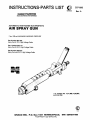
INSTRUCTIONS-PARTS LIST
OJ
OIlACO
307-896
Rev. A
This manual contains IMPORTANT
WARNINGS and INSTRUCTIONS
READ AND RETAIN FOR REFERENCE
AUTOMATIC HIGH-RANGE ELECTROSTATIC
AIR SPRAY GUN
7 bar (100 psi) MAXIMUM WORKING PRESSURE
Part Number 907-292
Spray Gun & 75 ft. High Voltage Cable
Part Number 956-112
Spray Gun & 50 Ft. High Voltage Cable
Part Number 956-610
Spray Gun with 25 Ft. High Voltage Cable
u.s.
PATENT NO. 4,241,880; 4,335,861;
and 4,501,394
H003
GRACO INC. P.O. Box 1441 MINNEAPOLIS,
©COPYRIGHT 1988 GRACO INC.
MN 55440-1444
TABLE OF CONTENTS
WARNINGS ...................................................................... 2
HOW THE ELECTROSTATIC AIR SPRAY GUN WORKS .......... 4
INSTALLATION
Typlc.1 In.t.lI.tlon ......................................................... 4
V.ntll.te the Spr.y Booth ................................................ 4
Conn.ct the High Voltage Power Supply ........................... 4
Connect the High Volt.ge Ca........................................... 15
Ch.ck the Electrical Grounding ........................................ 15
Mount the Spr.y Gun ...................................................... 15
Connect the Air Une........................................................ 15
Connect the High Volt.ge Control .................................... 8
Conn.ct the fluid Une ..................................................... 8
OPERATION
Op.r.tlng Ch.ckllat ........................................................ 1
Fllt.r the fluid ................................................................ 1
Adju.t the Spr.y P.tt.rn ................................................. 8
CI •• nlng ........................................................................ 7
CI ••n the Air C.p and fluid Tip ......................................... 7
Flu.hlng .................•.......................••............................. 7
SERVICE
Spray Patt.rn Troubl ••hootlng Ch.rt ................................ 8
Gun Op.r.tlon Troubl ••hootlng Ch.rt .............................. 9
EI.ctrlc.1 Troubl ••hootlng Ch.rt ..................................... 10
Gun DI•••••mbly .......................................................... 11
EI.ctrod. R••I.tor R.pl.c.m.nt ..................................... 11
fluid N••dl. R.mov.1 .................................................... 12
fluid Needle Replacement .............................................. 12
B.rr" Remov" ............................................................. 12
fluid Pecking Repl.cement ............................................ 12
B.rrel R.....mbly .••••••••.•••••••••••••••••••••••••••••••••.••••.•.••••.• 13
R..lator Tubel R..lator Repl.cement .............................. 13
R..lator Tube Reg ......ng ......... ~ .................................... 13
Servicing the Actuator .................................................... 14
F.n Air Valve Replacement ............................................ 14
AIR CAP CONSUMPTION .nd FLUID np FLOW RATE CHART 11
Air Cape ....................................................................... 11
Air Cap A ...mbll.......................................................... 11
PARTS DRAWING ........................................................... 11
PARTS LIST .................................................................... 17
HOW TO ORDER REPLACEMENT PARTS ........................... 17
ACCESSORIES ................................................................ 18
TECHNICAL DATA ............................................. B.ck Cover
The words Warning, Caution, and Not. are used to classify information within this manual.
WARNING: Alerts user to avoid or correct conditions that could cause
personal injury.
CAUTION: Alerts user to avoid or correct conditions that could cause
damage to or destruction of equipment.
NOTE: Identifies essential procedures or extra information.
WARNING
•c!J
Instruction.
SERIOUS BODILY INJURY, EXPLOSION, FIRE, OR ELECTRIC
SHOCK CAN OCCUR IF THE PRECAUTIONS BELOW ARE NOT
FOLLOWED.
READ AND UNDERSTAND ALL INSTRUCTION MANUALS,
TAGS, AND WARNING LABELS BEFORE OPERATING EQUIPMENT.
ELECTROSTATIC EQUIPMENT SHALL ONLY BE USED BY TRAINED
PERSONNEL WHO SHALL BE FULLY CONVERSANT WITH THE REQUIREMENTS STATED WITHIN THIS INSTRUCTION MANUAL.
EQUIPMENT MISUSE HAZARD
General Safety
Any misuse of the spray equipment or acc8880ries, such 88
overpressurizing, modifying parts, using incompatible
chemicals and fluids, or using worn or damaged parts, can
cause them to rupture and result in serious bodily injury, fire,
explosion or property damage.
NEVER point the spray gun at anyone or at any part of the
body. NEVER put hand or fingers over the spray tip.
ALWAYS follow the Pre..ure Relief Procedure, to the
right, befo~e cleaning or removing the fluid tip or servicing any
system equipment.
NEVER try to stop or deflect leaks with your hand or body.
NEVER alter or modify any part of this equipment; doing so
could cause it to malfunction.
CHECK all spray equipment regularly and repair or replace
worn or damaged parts immediately.
This gun has a maximum working pressure of 7 bar (100 psi).
Never exceed the maximum working pressure of the gun or
any other component or accessory used in the system.
2
307-896
Pressure Relief Procedure
To reduce the risk of serious bodily injury, including splashing
in the eyes, injury from moving parts or electric shock, always
follow this procedure when shutting off the system, when
checking or servicing any part of the spray system, when installing, cleaning or changing fluid tips, and whenever you
stop spraying.
1. Turn off the high voltage power supply.
2. Turn off the air and fluid supply to the gun.
3. Trigger the gun into a grounded metal waste container to
relieve fluid pressure.
4. Open the pump drain valve, having a grounded metal waste
container ready to catch the drainage.
5. Leave the pump drain valve open until you are ready to
spray again.
Bleed·Type AIr Shutoff Valve and fluid Drain
Valve Required
These two accessories are required in your system to help
reduce the risk of serious bodily injury, including splashing in
the eyes and injury from moving parts if you are adjusting or
repairing the pump.
The bleed-type air shutoff valve relieves air trapped between
this valve and the pump after the air regulator is shut off. Trap-
All parts of the electrostatic spray system must be properly
grounded to reduce the risk of static electricity discharge.
Static electricity is created by the high velocity flow of fluid
through the pump and hose and the spray gun's
power supply. Ungrounded objects can become electrically
charged and sparking may occur. Sparks can ignite fumes
from solvents, fluid being sprayed, dust particles and other
flammable substances, which can cause a fire or explosion
and result in serious bodily injury and property damage.
If you experience any sparking or feel even a slight shock,
STOP SPRA YING IMMEDIA TEL Y. Check for proper grounding of the entire system. Be sure you have corrected the problem before starting to spray again.
The minimum spraying distance from the gun tip to the
workpiece is 100 mm (4 in.). Holding the gun any closer to the
workpiece will cause sparking.
Grounding
The following are minimum requirements for grounding a
basic electrostatic system. Your system may include other
equipment or objects which must also be grounded. Always
check your local electrical code for detailed grounding instructions. Be sure your system is connected to a true earth
ground.
1. Pump: ground by using a ground wire and clamp as
described in your separate pump instruction manual.
2. Air compressors: ground according to the manufacturer's
recommendations.
3. High voltage power supplies: must be properly grounded
and located outside the spray area. Ground according to
the manufacturer's recommendations.
4. High voltage cable: obtain grounding through connection
of an undamaged cable to a properly grounded power
supply.
5. All electric cables going to the power supply must be properly grounded.
6. Spray gun: obtain grounding through connection to properly grounded high voltage cable.
7. Object being sprayed: keep the workpiece hangers clean
and grounded at all times. Contact points must be sharp
points or knife edges.
pad air can cause the pump to cycle unexpectedly. Locate the
valve within easy reach of the pump.
The fluid drain valve assists in relieving fluid pressure in the
displacement pump, hose and gun; triggering the gun to
relieve pressure may not be sufficient.
8. All electrically conductive objects or devices, in the spray
area, including paint containers and wash cans, must be
properly grounded.
9. All persons entering the spray area: shoes must have conductive soles, such as leather, or personal grounding
straps must be worn. Rubber or plastic soles are not conductive.
10. The floor of the spray area must be electrically conductive
and grounded. Do not cover the floor with cardboard or
any non-conductive material which would interrupt
grounding continuity.
11. Flammable liquids in the spray area must be kept in
approved, grounded containers. Do not store more than
the quantity needed for one shift.
12. All solvent pails: use only grounded metal pails, which are
conductive. Do not place the pail on any non-conductive
surface, such as cardboard or paper, which would interrupt grounding continuity.
flushing and Cleaning Safety
To reduce the risk of static sparking or splashing, always
follow the Pre••ure Renef Procedure on page 2, and
remove the fluid tip before flushing. Use the lowest possible
pressure and use a grounded metal waste container.
Be sure the high voltage power supply is OFF during flushing.
NEVER use solvents having a flash point of less than 21°C
(70 0 F) to clean the gun. NEVER use solvents having a flash
point of less than 38°C (100 0 F) to clean the spray system.
AL WAYS remove all solvent from the system before reactivating the spray gun.
Use only non-sparking tools to clean residue from the booth
and hangers.
Ventilate the Spray Booth
To prevent hazardous concentrations of toxic and/or flammable vapors, spray only in a properly ventilated spray booth.
The High Voltage Power Supply must be electrically interlocked with the ventilators to prevent operation of the Power Supply unless ventilating fans are operating.
NEVER operate the spray gun unless the ventilating fans are
operating.
IMPORTANT
United States Government safety standards have been adopted under the Occupational Safety and Health Act. These standards - particularly the General Standards, Part 1910.107 and any other appropriate regulations-should be consulted in connection with the installation, operation and maintenance of electrostatic spray painting equipment.
307-896
3
How the Electrostatic Air Spray Gun Works
A transformer supplies high voltage current through the
cable to the gun's ionizing electrode, where the electrostatic field is developed. The pump supplies fluid
through the hose and gun, where it is electrostatically
charged as it passes the ionizing electrode. The charged
fluid is attracted to the grounded workpiece, wrapping
around it and coating all surfaces.
INSTALLATION
TYPICAL INSTALLATION
p
G
WARNING
SIGN
H
NON-HAZARDOUS AREA
KEY
A
Air Supply Line
B
Air Line Filter
C
Air Line Lubricator
D
Pump
EON-OFF (D.P.-D.T.) Switch
F
Electric Power Line
G
Air Supply Shutoff Valve (Bleed-type)
H
High Voltage Power Supply
J
K
L
M
N
o
P
Air Regulator
Air Filter (40 micron)
Atomizing Air Line
High Voltage Cable
Fluid Line
Remote Switch & Lights Wiring
Normally Closed, 3-way Air Solenoid
Valve or 3-way Manual Valve
The Typical Installation shown above is only a guide for
selecting and installing electrostatic air spray systems. It
is not an actual system design. The particular type and
size system for your operation must be custom designed
for your needs. For assistance in designing a system,
contact your Graco representative.
- - - - - - W A R N I N G - - - - -......
Installing and servicing this equipment requires access to parts which may cause electric shock or
other serious bodily injury. Do not install or service
this equipment unless you are qualified.
Be sure your installation complies with national,
state and local codes for the installation of electrical apparatus in a Class 1, Group 0; Divisions 1
and 2 Hazardous Location.
Warning Signs
Mount warning signs in the spray area where they can
easily be seen and read by all operators. See the Accessories section on page 18.
4
307-896
HAZARDOUS AREA
Q
R
S
T
U
V
W
EE
FF
Electrostatic Automatic Gun
Fluid Regulator
Remote Switch & Lights
Relay for Electrical Signal
Connection Between Relay & Power Supply
Cylinder (CYU Air Line
Electrical Signal Required to Actuate Air
Fluid Filter
Drain Valve
Ventilate the Spray Booth
..------WARNING - - - - - - - .
To prevent hazardous concentrations of toxic
and/or flammable vapors, spray only in a properly
ventilated spray booth. The High Voltage Power
Supply must be electrically interlocked with the
ventilators to prevent operation of the power supply unless the ventilation fans are operating. NEVER
OPERATE THE SPRAY GUN UNLESS VENTILATION FANS ARE OPERATING.
Check and follow all of the National, State and
Local codes regarding air exhaust velocity
requirements.
Check and follow all local safety and fire codes and
OSHA standard 1910-107(b)(5)(i).
NOTE:
High velocity air exhaust will decrease the
operating efficiency of the electrostatic
system. Air exhaust velocity of 31-46 linear
meters/minute (100-150 ft/min) should be
sufficient.
Connect the High Voltage Power Supply
The electrical connections to the Power Supply (H)
must be performed by a qualified electrician, in accordance with all applicable local, state and national codes.
z--~=-
Connect the High Voltage Cable
Grease the resistor tube as described in Resistor Tube
Regreasing on page 13.
Route the High Voltage Cable (M) from the gun to the
Power Supply. Lubricate o-rings with petroleum jelly.
Connect the High Voltage Cable to the Power Supply.
To avoid permanent indentations of the cable and cable
failures due to unnecessary stress to the cable, follow
these steps:
1.
Support the cable overhead to keep people from
walking on it and vehicles driving over it.
2.
DO NOT clamp the cable too tightly at supports.
3.
Avoid sharp kinks and bends in the cable.
Check the Electrical Grounding (See Fig 1)
...------WARNING - - - - - - - .
Proper electrical grounding of every part of your
system is essential. For your safety, read the warning section, FIRE OR EXPLOSION HAZARD, on
page 3. Ground the system as explained there.
Then check your system as explained below.
1.
Make sure the High Voltage Power Supply is properly grounded and located outside the spray area.
The Power Supply case and spray gun actuator
can become charged if the case is not well
grounded. The ground wire is part of the high
voltage circuit and must, without fail, be connected to a true earth ground. As an added
precaution, attach a separate ground wire to the
case of the High Voltage Power Supply.
KEY
M
X
Y
Z
High Voltage Cable
Ohmmeter
Gun
Grounded Object
Fig 1_ _ _ _ _ _ _ _ _ _ _ _ _ _ _ __
Connect the Air Lines (Refer to the Typical
Installation Drawing)
1. Install an air line filter (B) to ensure a clean, dry air
supply to the gun. Dirt and moisture in the line can
ruin the appearance of your finished piece, and
cause malfunction of the Power Supply.
2.
Install an air line lubricator (C) as close to the pump
(D) as possible.
3.
Install a normally closed, 3-way air solenoid (P), or
hand valve in the air supply line (A).
4.
Install an air regulator (E) on the pump and gun air
supply lines to control air pressure to pump and
gun.
5.
Install a bleed-type air shutoff valve (G) on the main
air line and each gun air supply line to shut off air to
the pump and/ or gun(s). Install an additional bleedtype valve on each pump air supply line to relieve air
trapped between this valve and the pump after the
air regulator is shut off. See Bleed-Type Air
Shutoff Valve and Fluid Drain Valve Required,
warnings section, page 3.
2.
Shut off the Power Supply and the air and fluid lines
to the gun.
3.
Have a qualified electrician check the electrical
grounding continuity of the spray gun. Use an ohmmeter (X) to measure resistance between the actuator of the gun (Y) and a true earth ground (Z).
The resistance should be less than 20 ohms.
6.
Connect the atomizing air line (U from the air line to
the gun's 114 npt(f) atomizing air inlet. Refer to the
Typical Installation drawing .
...------WARNING - - - - - - - ,
7.
Connect the cylinder air line (V) from the solenoid
valve to the gun's 1/4 npt(f) cylinder air inlet.
If the resistance is over 20 ohms, the gun is not
property grounded, and the system may be hazardous. Check again that you have properly grounded your system components; see FIRE OR EXPLOSION HAZARD, on page 3. Since the gun is
grounded through connection to an undamaged,
properly grounded, high voltage cable (which is
grounded through connection to a properly
grounded power supply), check for a grounding
problem with the cable and power supply first. BE
SURE you have corrected the problem before using the system.
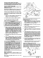
Mount the Spray Gun
Mount the gun (Q) on a stationary support or on a
reciprocating arm. The mounting rod must be properly
grounded.
Mount the gun head 254 to 300 mm (10 to 12 in.) from
the workpiece.
Adjust the Air Bleed Valve (See Fig 2)
If the gun is mounted above the workpiece, remove the
plug (11), adjust the air bleed valve (43) to allow slightly
more atomizing air through the front of the gun, then
replace the plug (11), This helps prevent fluid from dripping from the front of the gun onto the workpiece.
11~'~
43
)
~"""'
.......,,~/
·~.~~1··~\/~
\UI) V
::: __ ~'7
Fig 2 _ _ _ _ _ _ _ _ _ _ _ _ _ _ _ __
307-896
5
Connect the High Voltage Control
An electrical signal is required to actuate the normally
closed, 3-way air solenoid valve (P). The air solenoid
valve opens the cylinder air to the actuator, which opens
the fluid needle, allowing the fluid to spray. The same
signal (W) that actuates the air solenoid valve actuates a
relay (T). A set of contacts from this relay is connected
to the 120 KV Power Supply. This allows the High
Voltage to be turned on and off automatically.
Connect the Fluid Line
Before connecting the fluid line (N), blow it out with air,
and flush it with solvent. Be sure the solvent you use is
compatible with the fluid to be sprayed.
Connect the fluid line (PTFE) from the outlet of the pump to
the 1/8 ~ube Fitting inlet of the gun. Install a fluid filter (EE)
and drain valve (FF) at the pump outlet. The drain valve
assists in relieving fluid pressure in the displacement
pump, hose and gun. See Bleed-Type Air Shutoff Valve
and ~Iuid Drain Valve Required, Warnings Section. Install
a flUid regulator (R) between pump and gun to control fluid
pressure to the gun.
Color Change/Circulating System Option
Remove the plug (13) and o-ring (66) from one side of
the gun barrel, and install a 1/4 npt(f) elbow (see Accessories Section) in the gun barrel inlet.
KEY
13
88
Plug
O-Ring
Fig 3 _ _ _ _ _ _ _ _ _ _ _ _ _ _ __
...------WARNING - - - - - - - .
Do not use metal fittings at the gun head. Metal
fittings can cause sparking and result in fire or explosion and cause serious bodily injury.
For color change, connect a fluid line to the elbow.
Remove the fluid tube assembly and install a flushing
valve (see Accessories Section) in the gun barrel fluid inlet. Connect the fluid flushing line to the flushing valve.
Connect an air line to actuate the flushing valve.
For a circulating system, connect the fluid return line to
the elbow.
OPERATION
...------WARNING - - - - - - - .
For Your Safety, always follow the Pressure
Relief Procedure on page 2 when shutting off
the system, when you stop spraying, and before
checking, servicing, installing, cleaning or changing any part in the system.
Operating Checklist
Check the following list daily, before starting to operate
the system, to help assure you of safe, efficient
operation.
Filter the Fluid
Filter the fluid to remove coarse particles and sediment
which could clog the spray tip.
Adjust the Spray Pattern
This gun can atomize many fluids with different
viscosities and at various flow rates. Follow these steps
to establish the correct fluid flow and air flow:
1.
Set the atomizing air pressure at 2 bar (30 psi) and
fluid pressure at 0.25 bar (3 to 4 psi).
2.
Choose the correct fluid tip and air cap combination
for your application. (See the Air Cap Consumption
and Fluid Tip Flow Rate Chart), page 15. Both flow
rate and viscosity must be considered. A 1.2 mm
(0.047 in.) fluid tip is furnished with the gun.
3.
Turn on the High Voltage Power Supply.
4.
Adjust the fluid flow by using the fluid pressure
regulator installed in the fluid line. (See Accessories
Section).
5.
For fine adjustment, use the fluid adjusting screw
(39) located at the rear of the gun. See Fig 4. Turn
the knob clockwise to reduce the amount of fluid
being sprayed, and counterclockwise to increase
the amount being sprayed.
6.
Use an air pressure regulator to adjust the pressure
for the desired degree of atomization. Always use
the lowest air pressure possible for most efficiency.
7.
Use the fan valve (57) to change the shape of the
spray pattern. See Fig 4. Turn fan valve knob
counterclockwise for a wide pattern and clockwise
for a solid, round pattern.
_ 1. Be sure all operators are properly trained to safely
operate an electrostatic air spray system.
_ 2. Be sure all operators are trained how to properly
and completely relieve system pressure.
_ 3. Be sure the system is thoroughly grounded. See
FIRE OR EXPLOSION HAZARD on page 3, and
Check the Electrical Grounding on page 5.
_ 4. Be sure the operator and all persons entering the
spray area are properly grounded.
_ 5. Be sure ventilation fans are operating properly.
_ 6. Be sure the workpiece hangers are clean and
grounded. Contact points must be sharp points
or knife edges.
_ 7. Be sure all refuse is removed from spray booth.
_ 8. Be sure all flammable liquids in the spray booth
are in approved, grounded containers.
_ 9. Be sure all conductive objects within 6 m (20 ft)
of the gun- are electrically grounded and the floor
of the spray area is electrically conductive and
grounded.
6 307-896
KEY
39
fi1
Fluid Adjusting Screw
Fan Valve Assembly
39
Clean the Air Cap and Fluid Tip
Equipment needed:
Soft bristle brush (supplied).
Fluid tip wrench (supplied).
Solvent compatible with fluid being sprayed.
Procedure:
1. Turn off the Power Supply.
2.
Shut off the fluid and air supply lines to the gun.
3.
Actuate the gun to release the air and fluid pressure
trapped in the lines.
4.
Note the position of the fluid adjusting screw (39).
See Fig 4. Turn the fluid adjusting screw to relieve
spring tension on needle assembly.
Adjust the system's control device, so the gun starts
spraying just before meeting the workpiece, and stops
as soon as it has passed.
5.
Remove the air cap retaining nut (27) and air cap
(32). See Fig 5. With the wrench (83b) supplied,
remove the fluid tip (30).
See the Spray Pattern Troubleshooting Chart in the
Service section for additional information.
6.
Use the soft br.c;tle brush (83a) supplied and solvent
to clean air cap, fluid tip, and front part of the gun.
When all adjustments of atomizing air, fluid pressure,
and fan pattern are made, the high voltage can be turned on and operation can begin.
7.
Screw the fluid tip back into the gun. Tighten the tip
securely with the wrench (83b). Torque the fluid tip
to 1.1 to 1.4 N·m (10 to 12 in-Ib). See Fig 5.
Fig 4 _ _ _ _ _ _ _ _ _ _ _ _ _ _ _ __
NOTE:
When increasing to a wide, flat pattern, you
may have to increase the supply of fluid to
the gun to maintain the same amount of
coverage over a large area.
55
Cleaning
~-----WARNING-----.....
For Your Safety. always follow the Pressure
Relief Procedure on page 2 when shutting off the
system, when you stop spraying and before checking, servicing, installing, cleaning or changing any
part in the system.
1. Clean the fluid and air line filters daily.
2. Clean the outside of the gun daily with a soft cloth
dampened in a compatible solvent.
3. Clean the air cap and fluid tip daily, minimum. Some
applications require more frequent cleaning.
Replace the fluid tip and air cap if they are damaged.
See Clean the Air Cap and Fluid Tip below.
{..
\ ~
(J
KEY
27
30
32
56
Retaining Nut
Fluid Tip
Air Cap
Electrode Resistor
Fig 5 - - - - - - - - - - - - - - - - - 8. Replace the retaining nut and air cap carefully to
avoid bending the electrode wire. Tighten the retaining nut so it is snug, allowing the air cap to turn
with resistance. If it is too tight, the spray pattern
will be distorted.
9.
5. Check all of the work hangers for build-up of
material; clean them, if necessary.
Flushing
Do not use metal tools to clean the air cap holes as
this may scratch them, and make sure the electrode wire is not damaged. Scratches in the air cap
holes or a damaged electrode wire can distort the
spray pattern.
j
~~32
~27
4. Check the electrode resistor (55). Straighten it if it is
bent, and replace it if it is broken or damaged. See
page 11 for replacing the electrode resistor.
.....-----CAUTION - - - - - - - - .
//
Reset the fluid adjusting screw (39) to its original
position. Measure the travel of the resistor electrode. Full travel should be 2.5 mm (0.10 in.). The
gun is now ready for spraying.
.....-----WARNING-----......
For Your Safety. always follow the Pressure
Relief Procedure on page 2 when shutting off the
system, when you stop spraying and before checking, servicing, installing, cleaning or changing any
part in the system.
1. Turn off the high voltage power supply.
Do not use any cleaning method which may
allow solvent into the gun air passages. Clogged air passages cause poor atomization and excessive current demands. Point the gun down
while cleaning to prevent dirty solvent from running back into the air passages. NEVER IMMERSE
THE GUN IN SOLVENT.
2. Disconnect and plug the fluid supply line.
3. Connect the solvent supply to the gun.
4. Run solvent through the gun.
5. Disconnect the solvent supply.
Clean all parts with a non··conductive solvent,
compatible with the fluid being sprayed. Conductive solvents can cause the gun to malfunction.
6. Reconnect the fluid supply line.
7. Trigger the gun until it is clean of solvent.
307-896
7
SERVICE
~----------------------------VVARNING----------------------------~
Installing and servicing this equipment requires access to parts which may cause electric shock or other serious
bodily injury. Do not install or service this equipment unless you are qualified.
Before servicing the tip or gun, and before disassembling the gun, ALWAYS follow the Pressure Relief Procedure on page 2. Disconnect the fluid hose from the gun.
NOTE:
Check all of the possible remedies in the Troubleshooting Charts before disassembling the gun.
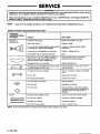
SPRAY PATTERN TROUBLESHOOTING CHART
PROBLEM:
IMPROPER SPRAY
PATTERN
Fluttering or
Spitting spray
IKlCJ~
c::
e
:?
~
~
<!>
CAUSE
SOLUTION
Insufficient fluid supply
Adjust fluid regulator or fill tank.
Leak in the fluid line
Tighten or repair
Dry or worn fluid needle packing or loose packing
nut permits air to get into fluid passage.
Lubricate or replace packing, tighten
packing nut.
Loose fluid tip or damage fluid tip taper seat.
Tighten or replace fluid tip.
Dirt between fluid tip, taper seat and body.
Clean.
Fluid build up on air cap; partially clogged horn
holes. Full air pressure from clean horn hole
forces fan panern toward clogged end
Clean with soft brush or submerge in
suitable solvent and wipe clean.
Damaged fluid tip or air cap holes
Replace damaged part.
Fluid build up on the perimeter of fluid tip orifice,
or partially clogged fluid tip orifice
Remove obstruction. Never use a wire or
hard instruments.
Too high atomization air pressure
Reduce air pressure or adjust air adjusting
valve.
Fluid too thin
Regulate fluid viscosity.
Not enough fluid pressure
Increase fluid pressure.
Low atomization air pressure
Raise air pressure.
Fluid too thick
Regulate fluid viscosity.
Too much fluid
Reduce fluid flow, reduce fluid pressure
on pressure feed guns and/or adjust fluid
adjusting screw until proper pattern is
obtained.
Last coat of fluid applied too wet
Apply drier finish with multiple strokes.
Too much air pressure
Use least air pressure necessary.
Insufficient air pressure
Increase air pressure.
Non-uniform spray pattern
Clean or replace air cap.
0
Streaks
;8.
':':
.:,:';:-
i
NOTE: Some improper patterns are caused by the improper balance between air and fluid.
8 307-896
----------------
GUN OPERATION TROUBLESHOOTING CHART
PROBLEM
CAUSE
SOLUTION
Leakage from fluid packing nut.
Loose packing nut (23).
Tighten.
Worn needle packing (4).
Replace.
Air valve not seating properly.
Clean, service.
Air bleed valve is open.
Check, adjust or close as required.
See Fig 2.
Resistor electrode worn or damaged.
Replace.
Worn fluid seat.
Replace fluid tip and/or resistor
electrode.
Fluid packing (4) too tight.
Lubricate and adjust.
Loose fluid tip (30).
Tighten.
Adjusting screw (39) not set correctly.
Adjust.
Cylinder air going into gun not completely
shut off.
Turn off cylinder air.
Worn needle packing (4).
Replace packing.
Worn needle shaft (61).
Replace worn needle shaft.
Insufficient air pressure.
Increase, use least air pressure needed for good results.
Paint viscosity too high.
Thin paint or use larger fluid nozzle.
Fluid poorly mixed or filtered.
Remix or refilter fluid.
Improper thinner being used.
Use proper thinner.
Too much air pressure.
Reduce, use least air pressure needed
for good results.
Fluid thinned too much.
Properly thin fluid.
Fluid low.
Check, add if necessary.
Damaged air cap.
Replace air cap.
Dirty or clogged fluid tip.
Clean fluid tip.
Damaged fluid tip.
Check, replace fluid tip.
Air valve not actuating.
Check cylinder air, fluid needle packing (4), and needle. Replace parts as
necessary.
Damaged fluid needle.
Replace.
Exhaust air flow insufficient or not directed
properly.
Check for proper CFM, check baffles
and direction of air flow.
Equipment closer to ionizing tip than object
being sprayed.
Mount gun closer to target.
Misalignment between air cap and fluid tip.
Remove and clean air cap and fluid
tip as described in the Operation Section under To Clean or Change the
Air Cap and Fluid Tip (page 7).
Reinstall fluid tip finger tight. Using
the wrench supplied, tighten fluid tip
114 turn (torque to 1.1-1.4 N'm
(10-12 in-Ib)). Set locking pin to locked position. Reinstall air cap being
sure to tighten retaining nut until
snug only; allowing air cap to turn
with resistance.
Air leakage from front of gun.
Fluid leakage from front of gun.
Fluid leaks from rear needle packing
nut or drain hole.
"Orange Peel" finish.
Excessive spray fog.
No fluid sprays from gun.
Equipment covered with fluid.
Dirty air cap.
Aircap1
Fluid Tip
Aligned
•
Misaligned
307-896
9
ELECTRICAL TROUBLESHOOTING CHART
PROBLEM
CAUSE
SOLUTION
Poor wrap-around.
Parts poorly grounded.
Clean hangers, check for proper
ground on conveyer or track.
High exhaust velocity.
Reduce within code limits.
High fluid pressure.
Reduce pressure.
Fluid viscosity.
Check supplier for proper fluid for
electrostatic spray.
Low or no electrostatic voltage.
See below.
Faulty gun resistance.
Check; resistance should be 450
megohms ± 20 from the end of the
resistor electrode of gun to the end
of the High Voltage Cable, where it
connects to the Power Supply. If
resistance is lower check resistance
of resistor (62).
Improper distance between gun and
workpiece.
Adjust spraying distance to
203-305 mm (8-12 in.).
Too high atomizing air pressure.
Reduce air pressure.
Too low fluid resistivity.
Check fluid resistivity with paint
meter and probe (refer to instruction
manual 307-263).
Faulty power supply resistance.
Check power supply resistance. See
page 12.
Faulty needle electrode assembly.
Replace needle electrode assembly.
Power Supply is off.
Line Power Switch is OFF, should be
turned ON.
Fuse on inside of High Voltage
Power Supply is blown.
Replace fuse.
Power line voltage is incorrect.
Adjust for correct voltage.
Low or no electrostatic
wrap. (Spraying voltage
light does not come on).
Faulty High Voltage Power Supply.
See instruction manual included with
High Voltage Power Supply.
Low or no electrostatic
wrap. (Spraying voltage
light comes on then goes
off).
Gun held too close to part being
painted.
Increase distance between part and
gun.
Fluid is too conductive.
Lower conductivity of fluid.
Electrical short in the High Voltage
Cable.
Replace the High Voltage Cable.
Electrical short in gun.
Take gun apart and visually check the
resistor holder, the resistor well and
the needle well in the gun barrel for
dirt and/or damage. Clean and
replace parts as required.
Faulty High Voltage Power Supply.
See instruction manual included with
High Voltage Power Supply.
Faulty resistor in the resistor electrode assembly.
Replace the resistor electrode
assembly.
Resistor of gun not making a good
connection with contact inside of
gun body.
See Resistor Assembly Replacement
in this manual.
High Voltage Cable not making
good contact with resistor of gun.
Cable insulation punctured.
Replace conductive spring as required.
Low or no electrostatic
wrap.
Low or no electrostatic
wrap. (Spraying voltage
light is on all of the time).
Continued on page 11.
10 307-896
Replace cable.
ELECTRICAL TROUBLESHOOTING CHART
PROBLEM
CAUSE
SOLUTION
Low or no electrostatic
wrap. (Spraying voltage
light is on all of the time).
Continued from page 10.
Spring at transformer end of cable
not making good contact.
Stretch spring.
Electrical short in gun.
Take gun apart and visually check the
resistor holder, the resistor well and
needle well for dirt and/or damage.
Clean and replace parts required.
Faulty High Voltage Power Supply.
See instruction manual included with
High Voltage Power Supply.
Spraying voltage stays on
when gun is not actuated.
Gun actuating device is faulty.
Check actuating device, replace if
faulty.
Operator gets mild shock.
Operator not properly grounded or
is in contact with ungrounded
object.
Be sure floor is properly grounded.
Wear shoes with non-insulating
soles. Be sure operator is not in contact with or carrying (in clothing) any
metalic items which could build-up
electric charge.
Gun not properly grounded.
Be sure Graco air supply hose is being used and is properly grounded.
Workpiece not properly grounded.
Clean workpiece hangers. Check for
proper ground on conveyor or track.
Operator gets mild shock
when touching workpiece.
Gun Disassembly
.....- - - - - W A R N I N G - - - - - Installing and servicing this equipment requires access to parts which may cause electric shock or
other serious bodily injury. Do not install or service
this equipment unless you are qualified.
6.
Disconnect High Voltage Cable from Power Supply .
7.
Take the gun and cable assembly to the workbench
for repair.
NOTE:
Turn off the High Voltage Power Supply and
relieve all of the pressures trapped in the gun and
the lines before servicing any part of the system.
Follow the Pressure Relief Procedure on page 2.
NOTE:
Check all possible remedies in Troubleshooting Charts before disassembling gun.
.....----------CAUTION-------If the plastic parts of the gun must be held securely , ALWAYS clamp them in padded vise jaws to
prevent damage to the parts.
ALWAYS lubricate the o-rings and seals with
petroleum jelly.
ALWAYS remove the gun from worksite for service or repair. Service or repair area must be clean.
Because of the high operating voltage, the
High Voltage Cable resistor tube is filled with
dielectric grease. The High Voltage Cable
should not be removed from the gun, unless
replacement or regreasing is necessary.
Electrode Resistor Replacement (See Fig 6)
Remove the air cap and fluid tip as described in the
Operation Section under Clean the Air Cap and Fluid
Tip. Remove the electrode resistor (55) with the wrench
(83d) supplied. Install new electrode resistor with the
wrench. Do not overtighten .
r-------CAUTION - - - - - - . .
To avoid damaging the plastic threads, be very
careful when installing the electrode.
Install the air cap and fluid tip as described in the Operation Section under Clean the Air Cap and Fluid Tip.
KEY
To disconnect the gun from the High Voltage Power
Supply and the fluid supply:
1.
Turn off the high voltage at the Power Supply.
2.
Turn off the line voltage input to the Power Supply.
3.
Shut off the fluid pump and actuate the gun to
relieve the pressure.
4.
Disconnect the fluid hose and air lines from the gun.
5.
Flush the gun with a compatible solvent.
83d Wrench
83d
Fig 6 _ _ _ _ _ _ _ _ _ _ _ _ _ _ _ __
307-896
11
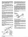
Fluid Needle Removal (See Figs 7 and 8)
Remove the air cap and fluid tip as described in the
Operation Section under Clean the Air Cap and Fluid
Tip. Turn the cylinder air off. Remove the electrode
resistor (55). Note the position of the adjusting screw
(39), and remove adjusting screw, retaining nut (35),
spring (63) and washer (68). Remove plate (37), by
removing the four screws (12). Loosen the needle packing nut (23) half a turn, using the wrench (83c) supplied.
With a long nose pliers pull out the needle assembly (64)
from the back of the actuator.
~~~39
KEY
12
35
37
39
63
68
Apply air to cylinder air port of the gun. Adjust the packing nut (23) with the wrench (83c) supplied (See Fig 8)
until there is light packing resistance on the needle.
If the fluid needle packing (4) or resistor tube (48) have
to be replaced, the resistor tube must be refilled with
dielectric grease as described in Resistor Tube
Regreasing, Regreasing with Barrel/Resistor Tube
Disassembled.
Barrel Removal
Remove the fluid needle as described in Fluid Needle
Removal.
~~35
68
Install the electrode resistor (55) with the wrench (83d)
supplied. See Fig 6. Install the air cap and fluid tip as
described in the Operation Section under Clean the Air
Cap and Fluid Tip.
Screw
Retaining Nut
Plate
Adjusting Screw
Spring
Washer
Loosen the barrel nut (28) using wrench (83b) supplied.
Pull the gun barrel forward off resistor tube. Be careful
not to lose the gasket (24). See Fig 12.
KEY
'0.
28
39
Barrel Nut
Adjusting Screw
83b Wrench
KEY
23
Packing Nut
83c Wrench
28
Fig 8
Fluid Needle Replacement
The fluid needle assembly (64) is sent from the factory
with retaining nuts (34) set for the correct length. If
these nuts are moved, reset them to the proper dimension shown in Fig 9.
Before replacing the needle assembly, thoroughly
lubricate with petroleum jelly. Twist the needle when
installing into gun.
KEY
34
64
Retaining Nuts
Fluid Needle Assy.
Fig 10 ________________________________
F:1:';i:~~~ ~
I
64
Fig 9 _ _ _ _ _ _ _ _ _ _ _ _ _ _ _ __
I
Install the plate (37) with the four screws (12). Install the
adjusting screw (39), retaining nut (35), spring (63) and
washer (68). Set adjusting screw (39) to its original position. See Fig 7.
12
307-896
Fluid Packing Replacement
Remove the gun barrel (60) as described in Barrel
Removal.
Remove the packing nut (23) from the rear of the barrel
using the wrench (83c) supplied. See Figs 8 and 11.
Remove the insulator (44) from the gun barrel.
Place the barrel on the bench in a vertical position with
the back of the barrel touching the bench. Insert the rod
(83e) supplied in the front of the barrel and gently tap
out the needle packing (4) and supports (20, 29).
KEY
4
Packing
20 SupPOrt
66
67
n
23
Packing Nut
28
29
44
Barrel Nut
Support
Insulator
60
Gun earrel
O-Ring
O-Ring
Fitting
28~~\
~~~
20~
6I~
29
,
~,~
~
c:/'/
i»®1'
~ ~66
~n
Fig 11 _ _ _ _ _ _ _ _ _ _ _ _ _ _ _ __
Check all of the parts for wear or damage and replace
them if necessary.
...------CAUTION - - - - - - - .
Use extreme care when handling the packing (4)
because it is very brittle. You may want to keep extra pac kings on hand.
Clean all parts in non-conductive solvent compatible to the fluid being used, such as Xylol or mineral
spirits. Use of conductive solvents can cause the
gun to malfunction.
To remove the resistor tube (48), lift up on it with one
hand, pushing it from the back of the gun body (56),
while pulling it from the front of the gun body with your
other hand.
Push the new resistor tube (48) back in from the front of
the gun body. The resistor tube should protrude
190 mm (7.5 in.) from the front of the gun body (56).
Screw the retainer (52) back into the gun body. Torque
the retainer to 20 to 27 N·m (15 to 20 ft-Ib).
Place the o-ring (8) into insert (53). Install the larger
bored end of the insert into the retainer (52) and over the
resistor tube (48). Slide the o-rings (6) in place over the
resistor tube.
Regrease the gun as described in Resistor Tube
Regreasing, Regreasing with Barrell Resistor Tube
Disassembled.
KEY
6
O-Ring
8
O-Ring
22 Retaining Ring
24 Gasket
28 Barrel Nut
48 Resistor Tube
52 Retainer
53 Insert
58 Gun Body
58 Spring
60 Gun Barrel
62 Resistor
~ 6~O
62\48~1
L 52~\{)
7j"'-
58"~.
TORQUE
TO
20-27 N.m
'
(16-20 ft-Ib)
/
It::)
Place packing nut (23), insulator tube (44), support (20),
packing (4) and support (29) over needle shaft.
r
i.
Barrel Reassembly
Make sure the three o-rings (66, 67) are in place in packing supports (20, 29). See Fig 11.
Insert the needle shaft assembly into the barrel and
tighten packing nut (23) with wrench (83c) supplied.
See Figs 8 and 11. Pull the needle back out of the barrel.
Fig 12 _ _ _ _ _ _ _ _ _ _ _ _ _ _ _ __
Assemble the barrel to the actuator, tightening the barrel nut (28) with the wrench (83b) supplied. See Fig 10.
Resistor Tube Regreasing (See Fig 12)
Install the needle into the gun as described in
Fluid Needle Replacement
NOTE:
Service Kit 217-114 (supplied with the gun)
contains all items needed to regrease the
resistor tube.
Regreasing With BarrelI Resistor Tube Disassembled
Resistor Tube/Resistor Replacement (See Fig 12)
Remove the barrel from the gun body as described in
Barrel Removal. Place a wrench on the flats of retainer
(52) and remove retainer from gun body. Remove retainer, packing (8), and insert (53), Inspect for damage,
replace as necessary. If insert (53) has burn marks,
replace it.
Remove the resistor (62) from the resistor tube (48).
Screw the grease fitting (82c) into the resistor end of the
resistor tube (48). Using the grease gun (82a) and dielectric grease (82b), fill the resistor tube until the grease
comes out of the end of the retainer (52), Remove the
grease fitting.
Clean all parts in non-conductive solvent compatible with the fluid being used, such as Xylol or
mineral spirits. Use of conductive solvents can
cause the gun to malfunction.
To install the resistor, first, cover the open end of the retainer (52) with your thumb to prevent too much grease
from being pushed out of the resistor tube (48) and retainer. The, face the plug end of the resistor toward the
front of the gun barrel (60), and push the resistor into
the resistor tube.
Remove spring (58) and o-rings (6). Inspect for damage
and replace if necessary. Check resistance of resistor
(62) using a megohmmeter. The resistor electrode (55)
should have 25 ± 5 megohms resistance.
Thoroughly wipe off any excess grease. Grease may
contaminate the fluid to be sprayed if allowed to seep into fluid passages of the gun. (Continued on page 14).
.-------CAUTION - - - - - -
307-896
13
Replace the barrel as described in Barrel Reas.embly.
Reassemble the electrode resistor (55), fluid tip (30), and
air cap (32) as described in Clean the Air Cap and
Fluid Tip in the Operation Section.
Remove the housing (38), and spring (17) from the
housing (65). Remove housing (65). Piston parts from
the gun body (56) will come out with the housing. Clean
all parts with compatible solvent and replace if worn.
NOTE:
NOTE:
If the gun is to be stored, cover the retainer
(52) opening to prevent contamination.
Reassemble the High Voltage Cable to the gun. Grease
should come out from the threads and bleed hole in the
cable swivel if the resistor tube is properly filled. Wipe
off the excess grease.
When the cable is assembled with the gun, the total
system resistance through the gun and cable should be
450 ± 25 megohms.
Regreasing With Only the High Voltage Cable Removed
If only the High Voltage Cable is removed from the gun,
the gun can be greased by back filling through the
retainer (52).
Attach the grease gun (82a) to the lubricant fitting of the
grease tube (82e). Insert the grease tube into the open
end of the insert (53) and retainer (52), through the
resistor tube cavity, until contact is made with the back
of the resistor (62).
Slowly fill the tube with dielectric grease (82b). As
grease fills the cavity, the grease tube will back out of
the insert (53), Continue filling until the grease tube
comes all the way out and the entire cavity is full.
Carefully wipe off any excess grease. Grease may contaminate the fluid to be sprayed if allowed to seep into
the fluid passages of the gun.
NOTE:
If the gun is to be stored, cover the retainer
(52) opening to prevent contamination.
Reassemble the High Voltage Cable to the gun. Grease
should come out from the threads and bleed hole in the
cable swivel if the resistor tube is properly filled. Wipe
off the excess grease.
When the cable is assembled with the gun, the total
system resistance through the gun and cable should be
450 ±25 megohms.
Servicing the Actuator (See Fig 13)
Remove the needle as described in Fluid Needle
Replacement. Remove the four screws (9) and
lockwashers (71).
~~
~
68~' ~~ ~~
38~®,,,.,,~,
,,~~:"
,~'"
17
~~i
"-~:
,
16
65
8
~-
~
c . ../~
\
~
,.'
'),-;::
~
\
J
6;
;:)
,
14
3539
9
\...71 KEY
""II',
'.
/
'Xl
40
8
9
O-Ring
Screw
14
18
17
35
38
39
40
63
66
88
71
O-Ring
Spring
Retaining Nut
Housing
A.djusting Screw
Piston
Spring
Housing
Washer
Lockwasher
U-C~pPacking
Fig 13 _ _ _ _ _ _ _ _ _ _ _ _ _ _ _ __
14 307-896
To inspect the o-ring (16), the piston (40)
must be tapped lightly through the center
hole of the housing (65) with a small punch.
When reassembling the actuator, lightly coat all the
parts with petroleum jelly. Slide the u-cup (14) onto the
piston. Install the piston into the rear housing (38), Place
the o-ring (16) onto the piston. Put the front and rear
housing together, and push the piston into the front
housing (65) using a dowel rod through the hole in the
front housing. Remove the rear housing to install the
spring (17). Then install the rear housing back onto the
front housing. Reassemble the remaining parts as
shown in Fig 13.
Assemble the remainder of the gun as described in Fluid
Needle Replacement.
KEY
AA
BB
CC
DO
Housing
Retaining Ring
Adjusting Screw
O-Ring
AA
TORQUE TO
20-27 N'm
(15-20 ft-Ib)
BB~ ~"'\'\'''~
~
Fig 14 _ _ _ _ _ _ _ _ _ _ _ _ _ _ _ __
Fan Air Valve Replacement
Place a wrench on the flats of fan valve assembly (57)
housing (AA) and remove it from the handle. Remove
the retaining ring (BB). Rotate the adjusting screw (CC)
counterclockwise removing it from valve housing (AA).
Clean all parts, inspect for wear or damage, and replace
if necessary. See Fig 14.
When reassembling the fan air valve assembly (57), use
petroleum jelly to lubricate o-ring (DO) and the threads
of the adjusting screw (CC).
After the retaining ring (BB) is reinstalled on the adjusting screw (CC), back the adjusting screw out of the
housing (AA) until it bottoms out against the retaining
ring (BB).
Apply Loctite® pipe sealant to the threads of the housing (AA). Torque the housing (AA) to 20 to 27 N·m
(14 to 20 ft-Ib) when replacing into the gun body (56).
AIR CAP CONSUMPTION AND FLUID TIP FLOW RATE CHART _ _ _Dm_ _WMmmlHS1i~gt*i]rn1Jm1~n:;;;%bWiitHfWJ
NOTE:
This is only a guide for selecting an air cap and fluid tip combination for your application. ALL TIPS AND
CAPS ARE INTERCHANGEABLE. Contact your Graco representative for further information.
RECOMMENDED AIR CAP AND FLUID TIP COMBINATIONS
TYPE OF FLUID
AND VISCOSITY
Low Production
Stains
Primers
Sealers
lacquers
15 to 22 seconds
(No.2 Zahn cup)
Medium Production
Primers
Lacquers
Enamels
Sealers
19 to 30 seconds
(No.2 Zahn cup)
Air Cap Air Consumption Pattern Shape
Part
m3/min at 2.1 bar and Length at
Number (CFM at 30 psn 254 mm (10 in.)
177-037
1n-848
0.34
(12.1)
177-034
0.24
(8.5)
0.34
(12.1)
Heevy end High Solid
Lacquers
Enamels
Epoxies
Urethanes
Over 28 seconds
(No.4 Zahn cup)
Round end
356 to 406 mm
(14 to 16 in.)
Flow Rate
ml/min
(oz/min)
181-298
1.0
(0.040)
In to 532
181-299
1.2
(0.047)
356 to 710
(12 to 24)
181-298
1.0
(0.040)
In to 532
Round end
330 to 381 mm
(1350 15 in.)
1.0
(0.040)
In to 532
181-299
1.2
(0.047)
355 to 710
(12 to 24)
181-300
1.5
(0.060)
591 to 1182
(20 to 40)
Round end
356 to 406 mm
(14 to 16 in.)
181-298
1.0
(0.040)
In to 532
1.0
(0.040)
In to 532
181-299-
1.2
(0.047)
355 to 710
(12 to 24)
181-300
1.5
(0.060)
591 to 1182
(20 to 40)
1.0
(0.040)
In to 532
181-298
180-739-
0.27
(9.2)
180-740
Low Volume-High Solid
Lacquers
Enamels
Epoxies
Urethanes
Over 28 seconds
(No.2 Zahn cup)
Round end
279 to 330 mm
(11 to 13 in.)
ID
mm
(In.)
181-298
177-848
High Production
Metallics
Lacquers
Enamels
19 to 30 seconds
(No.2 Zahn cup)
0.20
(7.0)
Fluid T1p
Part
Number
177-848
177-038
177-039
Round end
381 to 432 mm
(15 to 17 in.)
(6 to 18)
(6 to 18)
(6 to 18)
(6 to 18)
(6 to 18)
0.27
(9.2)
Round end
457 to 508 mm
(18 to 20 in.)
181-298
0.34
(12.1)
Round end
356 to 406 mm
(14 to 16 in.)
181-299
1.2
(0.047)
89 to 207
(3 to 7)
181-300
1.5
(0.060)
In to 355
181-299
1.2
(0.047)
355 to 710
(12 to 24)
181-300
1.5
(0.060)
591 to 1182
(20 to 40)
181-301
1.8
(0.070)
1035 to 1479
(35 to 50)
181-300
1.5
(0.060)
591 to 1182
(20 to 40)
181-301
1.8
(0.070)
1035 to 1479
(35 to 50)
0.28
(10.0)
0.29
(10.2)
Tapered end
381 to 432 mm
(15 to 17 in.)
Tapered end
356 to 406 mm
(14 to 16 in.)
(6 to 18)
(6 to 12)
• Air cap and fluid tip combination supplied with gun.
Air Caps
The following air caps can be ordered as accessories:
Part No.
1n-034
1n-036
1n-037
1n-039
180-739
180-740
Air Cap Assemblies
Air cap assemblies include a pre-assembled retaining
ring (part no. 176-930), retaining nut (part no. 176-968),
and air cap.
Part No.
217-454
217-455
217-456
217-457
218-996
220-386
Includes Air Cap:
1n-034
177-036
1n-037
1n-039
180-739
180-740
307-896 15
0)
<0
Q)
......
I
1
1
67
72
60
1
4
66
1
1
1
2
2
1
1
1
3
2
Qty.
29
58
24
6
7
8
10
14
16
20
Ref No.
4
Repair Kit 218-988
Must be ordered separately.
~ Consists of:
a;
72*
83e
r.....
Tool Kit 216-642
(Ref No. 83; Includes 83a-83f)
53
.';'
I
~I
II;
}.; ~
f,::::.;
~,·~
tm.
t: .
,
I
~~·
II
l~
.>;• • . .
x
.:~.~
G)
Z
~
~
:u
c
:u
....
en
-0
J>
REF
NO.
4
6
7
8
9
10
11
12
13
14
15
16
17
18
20
22
23
24
27
28
29
30
PART
NO.
*105-662
*103-338
*105-668
*105-796
105-797
*105-798
104-765
105-800
105-801
*598-706
106-144
*155-685
170-253
**172-045
*177-918
176-930
176-936
*178-271
176-968
176-969
*177-919
181-299
31
32
177-785
180-739
34
35
37
38
39
40
42
43
44
48
50
51
52
53
177-197
177-198
177-203
177-204
177-205
681-332
181-541
177-209
177-212
177-436
176-939
101-343
177-529
177-530
DESCRIPTION
PACKING, needle; PTFE
O-RING; Viton
O-RING: Viton
O-RING: Viton
SCREW, pnh; M4 x 0.7 x 45
O-RING; Viton (Part of Ref No. 64)
PLUG, pipe
SCREW, filh; M3 x 0.5 x 6
PLUG, pipe (Part of Ref No. 60)
PACKING, u-cup; UHMWPE
SETSCREW; M10 x 1.5 x 16
O-RING
SPRING, compression
LABEL, warning
SUPPORT, packing
RING, retaining
NUT, packing
GASKET, housing
NUT, retaining, air cap
NUT, barrel
SUPPORT, packing
FLUID TIP; 1.2 mm (0.47"); other
fluid tips available, see page 15
PLATE, designation, MAX WPR
AIR CAP, Other Air Caps Available
See Page 15
NUT, retaining (Part of Ref No. 64)
NUT, retaining
PLATE
HOUSING, retaining
ADJUSTING SCREW
PISTON, valve
SHAFT, actuator (Part of Ref No. 64)
VAL VE, bleed
INSULATOR
TUBE, resistor
PLUG; M12 x 1.25
SCREW, drive; 3/16" long
RETAINER, sleeve
INSERT
OTY
1
3
1
2
4
2
1
4
2
1
1
1
1
1
1
1
1
1
1
1
1
2
1
1
,
1
1
1
1
1
1
1
4
1
1
REF PART
NO. NO.
215-864
55
56
215-951
57
215-952
*727-566
58
60
216-068
61
220-214
62
216-112
63
724-391
64
220-215
65
66
217-066
*106-167
67
68
70
71
72
75
77
79
80
*106-174
102-360
177-839
157-021
*177-200
103-147
597-427
**176-898
162-453
81
722-615
82
82a
82b
82c
82d
82e
83
83a
83b
83c
83d
83e
83f
DESCRIPTION
OTY
RESISTOR, electrode
BODY, gun
FAN VALVE ASSY.
SPRING, compression
BARREL, gun; Includes items 13 & 66
NEEDLE ASSY (Part of Ref No. 64)
RESISTOR, primary
SPRING
NEEDLE ASSEMBLY
Includes items 10, 34,42 & 61
HOUS lNG, valve
O-RING; Kalrez (Qty 2, part of Ref No.
60)
O-RING; Kalrez
WASHER, flat; 3/16
SPACER
LOCKWASHER; int. tooth 3/16
GASKET
PLUG, pipe
FITTING
TAG, warning (not shown)
NIPPLE; 1/4 npsm(f) x 1/4 npt(m)
((not shown)
FITTING, hose; 114 npsm(f) x
1/4 npt(m) (not shown)
217-114 KIT, service (not shown)
Includes items 82a and 82e
728-224 .GREASEGUN
217-115 :LUBRICANT, can, 3.5 oz.
100-054 .FITTING, lubricant
177-927 .TOOL, packing removal
217-505 .GREASE TUBE
215-642 KIT, tool
Includes items 83a to 83f
105-749 .BRUSH, cleaning
177-004 .WRENCH, fluid tip
177-732 .WRENCH, packing nut
177-007 .WRENCH, needle
179-803 .ROD, packing removal
107-158 .WRENCH, resistor stud
4
1
1
1
4
1
1
1
1
2
2
1
1
2
1
1
1
-Supplied in Repair Kit 218988
··Extra warning labels and tags are supplied at no charge.
WARNING
When servicing, use only original Graco replacement parts. Use of other parts could alter the
grounding continuity of the gun.
HOW TO ORDER REPLACEMENT
PARTS_*~
1. To be sure you receive the correct replacement parts,
kit or accessories, always give all of the information
requested in the chart below.
2. Check the parts list to identify the correct part number;
do not use the ref. no. when ordering.
3. Order all parts from your nearest Graco distributor.
6 digit
PART
NUMBER
OTY
PART DESCRIPTION
307-896 17
...------WARNING------,
Never operate your equipment at a working
pressure rating that is higher than the lowest rated
component in your system. Lower rated components may not be able to withstand the
pressure developed by the pump and may rupture,
causing serious bodily injury or property damage.
HIGH VOLTAGE POWER SUPPLY 956-155
115 VAC, 50/60 Hz.
Contact your Graco distributor for information.
HIGH VOLTAGE CABLES
FOR POWER SUPPLY 956-155
217-413 8 m (25 ft) Cable
217-414 15 m (50 ft) Cable
217-415 23 m (75 ft) Cable
217-416 30 m (100 tt) Cable
217-417 46 m (150 tt) Cable
/
SAFETY WARNING SIGN
172-049- English
172-771- Spanish
172-149- French
172-1&O-German
GROUNDED AIR HOSE ASSEMBLY, Buna-N
217-089
12 bar (175 psi) MAXIMUM WORKING PRESSURE
0.31 10, with 1/4 npsm(fbe) 15 m (50 tt)
AIR HOSE ASSEMBLIES, Nylon
14 bar (225 psi) MAXIMUM WORKING PRESSURE
6.35 mm (0.25 in.) 10, 1/4 npsm(fbe)
216-630 8 m (25 tt) Air Hose Assembly
216-631 15 m (50 tt)Air Hose Assembly
O-RINGY
106-791
FLUID HOSE ASSEMBLIES, Nylon
14 bar (225 psi) MAXIMUM WORKING PRESSURE
6.35 mm (0.25 in.) 10, 1/4 npsm(fbe)
215-837 8 m (25 tt) Fluid Hose Assembly
216-838 15 m (50 tt) Ruid Hose Assembly
The accessories on this section of the page have not been tested by Factory Mutural.
FLUSHING DUMP VALVE 907-517
ELBOW, Nylon 108-173
Male, 1/4-18 nptf, 5/8-20
HIGH VOLTAGE POWER SUPPLY
ANALOG CONTROL - 956111
11 () VAC 50/60 Hz.
Contact your Graco distributor for information.
UNIVERSAL GUN BRACKET 590-236
RECIPROCAL GUN BRACKET 725-973
STATIONARY GUN MOUNTING STAND 722-562
STATIONARY GUN BRACKET 724-344
3-WAY AIR VALVE 722-602
NOTE:
18 307-896
All safety barriers and interlocks are to be
supplied by the customer.
ACCESSO AI ES (Must be purchased separately) nmMmtW*iimim::ti/@Mm:N?HM1mtJM:Wt:tiIrl:i::fil:·::• ·:~: @Wi.{<:\·/?::)i·
The accesaori.. on this page have not been tested by Factory Mutual.
STRAINER (AIR or PAINT) 202-271
52 bar (750 psi) MAXIMUM WORKING PRESSURE
With 60 mesh filter element.
~~
See instruction manual 306-655.
~
'-..
3/8npt~
~~~:: OUTLET
3/8 npt INLET
FILTER-REGULATOR ASSEMBLY 217-07&
14 bar (200 psi) MAXIMUM WORKING PRESSURE
With 1/2 npt(f) inlet, 1/4 npt(m) regulated outlets. With
a porous bronze 40 micron filter and a 100 micron mesh
inlet strainer. See instruction manual 307-476.
HIGH VOLUME AIR REGULATOR 206-199
0-9 bar (0-125 psi) Regulated Pressure
14 bar (200 psi) Steel Pressure Gauge
1/2 npt
~I1/2npt
,
-,~
\~
.~
FILTER and MOISTURE SEPARATOR 202-680
12.6 bar (180 psi) MAXIMUM WORKING PRESSURE
With 1/2 npt(f) inlet, (2) 1/4 npt(m) outlets, and (2)
1/4 npt regulated outlets. With a porous bronze 50
micron filter and a 100 micron mesh inlet strainer. See
instruction manual 306-273.
(-,
"'-/
STAINLESS STEEL FLUID PRESSURE REGULATORS
17 bar (250 psi) MAXIMUM WORKING PRESSURE
0.3-6.8 bar (5-100 psi) REGULA TED PRESSURE
1/4 npt air inlet (Model 214-980 only), 3/8 npsm fluid inlet, 3/8 npt fluid outlet and 1/4 npt gauge port.
SPRING OPERATED FLUID REGULATORS
214-896 Without pressure gauge and mounting tube.
214-708 With 6.8 bar (100 psi) pressure gauge and
gauge mounting tube.
214-971 With 6.8 bar (100 psi) chrome plated gauge
and stainless steel gauge mounting tube.
AIR OPERATED FLUID REGULATOR
214-980 1 bar (15 psi) MAXIMUM INBOUND AIR
PRESSURE
906-800 0-60 psi FLUID REGULATOR
906-800 EXTENDED LIFE REGULATOR
AIR LINE FILTERS
17.5 bar (250 psi) MAXIMUM WORKING PRESSURE
Reusable 40 micron filter with drain cock for cleaning
and drying air in spray systems.
108-148 3/8 npt(f) inlet and outlet.
108-149 1/2 npt(f) inlet and outlet.
AIR LINE LUBRICATORS
17.5 bar (250 psi) MAXIMUM WORKING PRESSURE
See instruction manual 307-316.
214-847 3/8 npt inlet and outlet.
214-848 1/2 npt inlet and outlet.
214-849 3/4 npt inlet and outlet.
PAINT RESISTANCE METER 722-886
Used with 722-860 to measure resistivity. See instruction manual 307-263.
REMOTE SWITCH & SIGNAL LIGHT 728-386
PAINT PROBE 722-860
Used with 722-886 resistivity meter. See instruction
manual 307-263.
BLEED-TYPE MASTER AIR VALVE (REQUIRED)
21 bar (300 psi) MAXIMUM WORKING PRESSURE
Relieves air trapped in the air line between the pump air
inlet and this valve when closed.
107-141 3/4 npt(m x f) inlet and outlet
107-142 1/2 npt(m x f) inlet and outlet
307-896 19
I
-n cm
---33~~·5in.)
,I
t--I:
. .·-------------(13 I n . ' - - - - - - - - - - - - - I
17 cm
(6.7 in.'
1/4 NPT AIR INLETS 12.5 em
SIDE~ in.1
121 OPPOSITE
16
44 em
1--------------------(17.3 in.'
TECHNICAL DATA
Operating voltage range
Maximum air working pressure
Maximum fluid working pressure
Minimum air cylinder operating pressure
Fluid inlet
Atomizing air inlet
Cylinder air inlet
Weight (with 50-foot cable)
(gun only)
Paint resistivity range
0-120 KV
10.4 bar (150 psi)
7 bar (100 psi)
3.5 bar (50 psi)
3/8 npsm(m)
1/4 npt(f)
1/4 npt(f)
8 kg (17 Ib 9 oz)
1.3 kg (2.85 Ib)
7 Megohm CM to infinity
THE GRACO WARRANTY AND DISCLAIMERS
WARRANTY
Graco warrants all equipment manufactured by it and bearing its name to be free from defects in material and workmanship on the date of sale
by an authorized Graco distributor to the original purchaser for use. As purchaser's sole remedy for breach of this warranty, Graco will, for a
period of twelve months from the date of sale, repair or replace any part of the equipment proven defective. This warranty applies only when the
equipment is installed, operated and maintained in accordance with Graco's written recommendations.
This warranty does not cover, and Graco shall not be liable for, any malfunction, damage or wear caused by faulty installation, misapplication,
abrasion, corrosion, inadequate or improper maintenance, negligence, accident, tampering, or substitution of non-Graco component parts. Nor
shall Graco be liable for malfunction, damage or wear caused by the incompatibility with Graco equipment of structures, accessories, equipment or materials not supplied by Graco, or the improper design, manufacture, installation, operation or maintenance of structures, accessories, equipment or material. not supplied by Graco.
This warranty is conditioned upon the prepaid return of the equipment claimed to be defective for examination by Graco to verify the claimed
defect. If the claimed defect is verified, Graco will repair or replace free of charge any defective parts. The equipment will be returned to the
original purchaser transportation prepaid. If inspection of the equipment does not disclose any defect in material or workmanship, repairs will be
made at a reasonable charge, which charges may include the the costs of parts, labor and transportation.
DISCLAIMERS AND LIMITATIONS
THE TERMS OF THIS WARRANTY CONSTITUTE PURCHASER'S SOLE AND EXCLUSIVE REMEDY AND ARE IN LIEU OF ANY OTHER
WARRANTIES (EXPRESS OR IMPLIED), INCLUDING WARRANTY OF MERCHANTABILITY OR WARRANTY OF FITNESS FOR A PARTICULAR PURPOSE, AND OF ANY NON-CONTRACTUAL LIABILITIES, INCLUDING PRODUCT LIABILITIES, BASED ON NEGLIGENCE OR
STRICT LIABILITY. EVERY FORM OF LIABILITY FOR DIRECT, SPECIAL OR CONSEQUENTIAL DAMAGES OR LOSS IS EXPRESSLY EXCLUDED AND DENIED. IN NO CASE SHALL GRACO'S LIABILITY EXCEED THE AMOUNT OF THE PURCHASE PRICE. ANY ACTION FOR
BREACH OF WARRANTY MUST BE BROUGHT WITHIN TWO (2) YEARS OF THE DATE OF SALE.
EQUIPMENT NOT COVERED BY GRACO WARRANTY
GRACO MAKES NO WARRANTY, AND DISCLAIMS ALL IMPLIED WARRANTIES OF MERCHANTABILITY AND FITNESS FOR A PARTICULAR PURPOSE, WITH RESPECT TO ACCESSORIES, EQUIPMENT, MATERIALS, OR COMPONENTS SOLO BUT NOT MANUFACTURED BY GRACO. These items sold, but not manufactured by Graco (such as electric motor, switches, hose, etc.), are subject to the warranty, if any, of their manufacturer. Graco will provide purchaser with reasonable assistance in making any claim for breach of these warranties.
Factory Branch••:Atlanta, Dalla., Detroit, Lo. Angele., We.t Caldwell (N.J.'
Sub.ldlary and Affiliate Companl••:Canada; England; Switzerland; France; Germany; Hong Kong; Japan
GRACO INC.
P. O. Box 1441
PRINTED IN U.S.A.
MINNEAPOLIS, MN
307-896 3/88
55440-1444