1
TECHNICAL MANU
AL
MANUAL
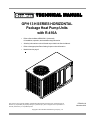
GPH 13 H SERIES HORIZONTAL
Package Heat Pump Units
with R-410A
• Refer to Service Manual RS6300011 (Horizontal)
for installation, operation, and troubleshooting information.
• All safety information must be followed as provided in the Service Manual.
• Refer to the appropriate Parts Catalog for part number information.
• Models listed on page 3
This manual is to be used by qualified, professionally trained HVAC technicians only. Goodman does not
assume any responsibility for property damage or personal injury due to improper service procedures or
services performed by an unqualified person.
Copyright © 2010 Goodman Manufacturing Company, L.P.
RT6332011r3
November 2010
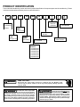
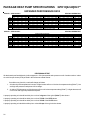
PRODUCT IDENTIFICATION
The model and manufacturing number are used for positive identification of component parts used in manufacturing. Please
use these numbers when requesting service or parts information.
G
P
BRAND:
G: Goodman®
Brand
H
13
24
H
4
1
A
VOLTAGE:
1: 208-230v
1ph/60Hz
A
MINOR REVISION:
A: Initial Release
PRODUCT
FAMILY:
H: Heat Pump
REFRIGERANT:
4: R-410A
PRODUCT
TYPE:
Package Unit
PRODUCT
SERIES:
SEER Rating
CONFIGURATION:
H: Horizontal
MAJOR REVISION:
A: Initial Release
NOMINAL
CAPACITY
24: 24,000 BTUH
30: 30,000 BTUH
36: 36,000 BTUH
42: 42,000 BTUH
48: 48,000 BTUH
60: 60,000 BTUH
WARNING
HIGH VOLTAGE!
Disconnect ALL power before servicing or installing this unit. Multiple power
sources may be present. Failure to do so may cause property damage, personal
injury or death.
Goodman will not be responsible
for any injury or property damage
arising from improper service or service procedures. If
you install or perform service on this unit, you assume
responsibility for any personal injury or property damage
which may result. Many jurisdictions require a license to
install or service heating and air conditioning equipment.
WARNING
2
Installation and repair of this unit
should be performed ONLY by individuals meeting (at a minimum)
the requirements of an "entry level technician" as specified by the Air-Conditioning, Heating, and Refrigeration
Institute (AHRI). Attempting to install or repair this unit
without such background may result in product damage,
personal injury or death.
WARNING
PRODUCT IDENTIFICATION
The model and manufacturing number are used for positive identification of component parts used in manufacturing. Please
use these numbers when requesting service or parts information.
GPH1324H41AB
GPH1330H41AB
GPH1336H41AC
GPH1342H41AB
GPH1348H41BB
GPH1360H41BB
WARNING
The United States Environmental Protection Agency (“EPA”) has issued various regulations regarding the introduction and disposal of refrigerants introduced into this unit. Failure to follow
these regulations may harm the environment and can lead to the imposition of substantial fines.
These regulations may vary by jurisdiction. Should questions arise, contact your local EPA office.
Do not connect or use any device
that is not design certified by
Goodman for use with this unit.
Serious property damage, personal injury, reduced unit
performance and/or hazardous conditions may result
from the use of such non-approved devices.
WARNING
To prevent the risk of property
damage, personal injury, or death,
do not store combustible materials or use gasoline or
other flammable liquids or vapors in the vicinity of this
appliance.
WARNING
3
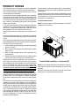
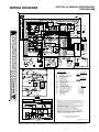
PRODUCT DESIGN
GPH Package Units are designed for outdoor installations
only in either residential or light commercial applications.
The connecting ductwork (Supply and Return) can only be
connected for horizontal airflow.
A return air filter must be installed behind the return air grille(s)
or provision must be made for a filter in an accessible location within the return air duct. The minimum filter area should
not be less than those sizes listed in the Specification Section. Under no circumstances should the unit be operated
without return air filters.
A 3/4" pipe is provided for removal of condensate water from
the indoor coil. In order to provide proper condensate flow, a
drain trap is supplied and shipped loose inside the unit for
field installation. (Do not reduce the drain line size).
Conditioned air is drawn through the filter(s), field installed,
across the coil and back into the conditioned space by the
indoor blower.
Package Heat Pump indoor sections are designed to accept
optional components such as auxiliary electric heaters and
circuit breakers. Provisions for these components have been
made at time of manufacture.
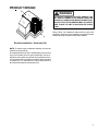
Location and Clearances
NOTE: To ensure proper condensate drainage, unit must be
installed in a level position.
Refrigerant flow control is achieved by use of restrictor orifices.
Package Heat Pump models use a combination of restrictor
orifices and thermostatic expansion valves for refrigerant flow
control.
Some heat pump models also have a suction line accumulator installed between the reversing valve and the compressor.
The object of the accumulator is to:
1. Provide a liquid refrigerant storage vessel during prolonged
system off cycles.
2. Store excess liquid refrigerant not needed by the system
while running.
3. Return oil and saturated vapor to the compressor at a
controlled rate.
4. Retain stored excess refrigerant during a sudden system
pressure fluctuation such as seen in defrost cycles.
Refrigerant flow control is achieved by use of restrictor orifices. GPH units use the FasTest Access Fitting System,
with a saddle that is either soldered to the suction and liquid
lines or is fastened with a locking nut to the access fitting
box (core) and then screwed into the saddle. NOTE: The
core must not be removed from the saddle until the
refrigerant charge has been removed. Failure to do so
could result in property damage or personal injury.
The single phase units use permanent split capacitor (PSC)
design compressors. Starting components are not required
for these units. A low microfarad run capacitor assists the
compressor to start and remains in the circuit during operation.
The outdoor fan and indoor blower motors are single phase
capacitor type motors. GPH1360H41* units have EEM indoor blower motors that are energized by a 24V signal from
the IBR and are constant torque motors with very low power
consumption. The EEM features an integral control module.
Air for condensing (cooling cycle) or evaporation (heating
cycle) is drawn through the outdoor coil by a propeller fan,
and is discharged vertically out the top of the unit. The outdoor coil is designed for .0 static. No additional restriction
(ductwork) shall be applied.
4
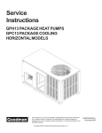
Outside Slab Installation - Horizontal (H)
NOTE: Roof overhang should be no more than 36" and provisions made to deflect the warm discharge air out from the
overhang.
Minimum clearances are required to avoid air recirculation
and keep the unit operating at peak efficiency.
PRODUCT DESIGN
36"
WARNING
UN
IT
PL
EN
UM
24"
PL
AT
FO
RM
RB
CU
36"
TO PREVENT POSSIBLE PROPERTY DAMAGE, THE
UNIT SHOULD REMAIN IN AN UPRIGHT POSITION
DURING ALL RIGGING AND MOVING OPERATIONS.
TO FACILITATE LIFTING AND MOVING IF A CRANE IS
USED, PLACE THE UNIT IN AN ADEQUATE CABLE
SLING.
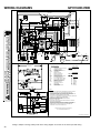
Refer to Roof curb Installation Instructions for proper curb
installation. Curbing must be installed in compliance with the
National Roofing Contractors Association Manual.
Rooftop Installation - Horizontal (H)
NOTE: To ensure proper condensate drainage, unit must be
installed in a level position.
In installations where the unit is installed above ground level
and not serviceable from the ground (Example: roof top installations) the installer must provide service platform for service person with rails or guards in accordance with local codes
or ordinances, or, in their absence, with the latest edition of
the Uniform Mechanical Code Section 305.
5
PRODUCT DESIGN
GPH1324-1360H41**
ELECTRICAL DATA (*Blower Only, Heat Mode)
Circuit #1
Model and Heat Kit Usage
GPH1324H41**
HKR05*,C*
HKR08*,C*
HKR10*,C*
GPH1330H41**
HKR05*,C*
HKR08*,C*
HKR10*,C*
HKR15*,C*
Circuit #2
Minimum Circuit
Ampacity
at 208 / 240V
Maximum
Overcurrent
Protection (amps)
at 208 / 240V
Minimum Circuit
Ampacity
at 208 / 240V
Maximum
Overcurrent
Protection (amps)
at 208 / 240V
Actual
kW & BTU
at 240V
24 / 27
33 / 28
45 / 51
30 / 30
40 / 40
60 / 60
----------
----------
4.75 / 16,200
7.00 / 23,800
9.50 / 32,400
24 / 27
30 / 30
----
----
4.75 / 16,200
34 / 39
45 / 52
45 / 52
40 / 40
60 / 60
60 / 60
------22 / 25
------30 / 30
7.00 / 23,800
9.50 / 32,400
14.25 / 48,600
GPH1336H41**
HKR05*,C*
HKR08*,C*
HKR10*,C*
HKR15*,C*
24 / 27
34 / 39
30 / 30
40 / 40
-------
-------
4.75 / 16,200
7.00 / 23,800
45 / 52
45 / 52
60 / 60
60 / 60
---22 / 25
---30 / 30
9.50 / 32,400
14.25 / 48,600
GPH1342H41**
HKR05*,C*
HKR08*,C*
25 / 27
34 / 39
30 / 30
40 / 40
-------
-------
4.75 / 16,200
7.00 / 23,800
46 / 52
46 / 52
46 / 52
60 / 60
60 / 60
60 / 60
---22 / 25
43 / 49
---30 / 30
60 / 60
9.50 / 32,400
14.25 / 48,600
19.50 / 66,500
25 / 28
34 / 40
46 / 53
46 / 52
46 / 52
30 / 30
40 / 40
60 / 60
60 / 60
60 / 60
---------22 / 25
43 / 49
---------30 / 30
60 / 60
4.75 / 16,200
7.00 / 23,800
9.50 / 32,400
14.25 / 48,600
19.50 / 66,500
26 / 30
36 / 40
48 / 54
30 / 30
40 / 40
60 / 60
----------
----------
4.75 / 16,200
7.00 / 23,800
9.50 / 32,400
48 / 54
48 / 54
60 / 60
60 / 60
22 / 25
43 / 49
30 / 30
60 / 60
14.25 / 48,600
19.50 / 66,500
HKR10*,C*
HKR15*,C*
HKR20*,C*
GPH1348H41**
HKR05*,C*
HKR08*,C*
HKR10*,C*
HKR15*,C*
HKR20*,C*
GPH1360H41**
HKR05*,C*
HKR08*,C*
HKR10*,C*
HKR15*,C*
HKR20*,C*
IMPORTANT NOTE: A separate power supply is required for the HKR heater kit.
WARNING
6
All wires and overcurrent protection devices are sized for use with electric heaters only and without
refrigeration. If heaters are not installed with above wire size, overheating and fire could occur. See
PACKAGE COOLING SPECIFICATIONS section for minimum circuit ampacity and maximum overcurrent
protection during refrigeration cycle.
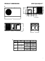
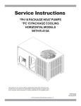
PRODUCT DIMENSIONS
GPH13[24-60]H41**
A
14.000
4.512
4.500
14.000
SUPPLY
14.000
RETURN
6.500
BACK VIEW
(DUCT OPENINGS)
66.542
B
34.075
Chassis
Small
Medium
Large
Model
A
B
GPH1324H41**
22.000
29.932
GPH1330H41**
22.000
29.932
GPH1336H41**
24.000
34.932
GPH1342H41**
24.000
34.932
GPH1348H41**
24.000
38.682
GPH1360H41**
24.000
38.682
7
GPH13[24-36]H41AB
GPH1336H41AC
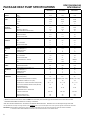
PACKAGE HEAT PUMP SPECIFICATIONS
GPH1324H41**
GPH1330H41**
GPH1336H41**
24,000
28,200
35,000
13.00
13.00
13.00
22,000
27,000
33,600
35°/33°F
17,600
20,400
27,000
17°/15°F
14,000
15,000
18,000
COOLING
COOLING CAPACITY, BTUH
CAPACITY
SEER
47°/43°F
HEATING
RATING
HSPF
7.7
7.7
7.7
208/230-60-1
208/230-60-1
208/230-60-1
AMPS
15.4
17.06
20.06
MIN CIRCUIT AMPACITY
18.6
20.6
24.2
30
30
40
SCROLL
SCROLL
SCROLL
RATED LOAD AMPS
12.8
14.1
16.7
LOCKED ROTOR AMPS
58.3
73.0
79.0
CONDENSER
HORSEPOWER
1/6
1/6
1/4
FAN MOTOR
RPM
815
815
830
FULL LOAD AMPS
1.1
1.1
1.5
LOCKED ROTOR AMPS
1.7
1.7
3.0
UNIT
VOLTAGE (NAMEPLATE)
ELECTRICAL
SPECIFICATION
MAX OVERCURRENT PROTECTION
COMPRESSOR
(2)
TYPE
CONDENSER FAN
BLADE DIAMETER (INCHES) / # OF BLADES
22 / 3
22 / 3
22 / 4
CONDENSER
FACE AREA (SQ. FT.)
13.4
13.4
17
COIL
NUMBER OF ROWS
1
1
1
FINS PER INCH
24
24
24
EVAPORATOR
HORSEPOWER - NO. OF SPEEDS
1/4 - 3
1/3 - 3
1/3 - 3
BLOWER
FULL LOAD AMPS
1.50
1.86
1.86
MOTOR
LOCKED ROTOR AMPS
2.2
3.2
3.2
MEDIUM
LOW
MEDIUM
1,075
MOTOR SPEED TAP - COOLING
RPM
1,075
1,075
EVAPORATOR
DIAMETER X WIDTH (INCHES)
9x6
9x6
9x8
BLOWER
RATED SCFM COOLING
875
1,080
1,205
MAX EXTERNAL STATIC PRESS ("w.c.)
0.5
0.5
0.5
EVAPORATOR
FACE AREA (SQ. FT.)
4.6
4.6
5.2
COIL
NUMBER OF ROWS
3
3
3
FINS PER INCH
GENERAL
FILTER SIZE (SQ. FT.)
INFORMATION
DRAIN SIZE (INCHES)
EXPANSION DEVICE (INDOOR / OUTDOOR)
REFRIGERANT CHARGE R-410A (OZS.)
POWER SUPPLY CONDUIT KNOCKOUT SIZE (INCHES)
LOW VOLTAGE CONDUIT KNOCKOUT SIZE (INCHES)
14
14
14
20 x 20 x 1
20 x 25 x 1
25 x 25 x 1
3/4"
3/4"
3/4"
ORIFICE (0.057 / 0.049)
ORIFICE (0.065 / 0.055)
ORIFICE (0.068 / 0.065)
115
140
125
3/4, 1, 1-1/4
3/4, 1, 1-1/4
3/4, 1, 1-1/4
1/2
1/2
1/2
22 / 50
22 / 50
22 / 50
LO PRESSURE SWITCH
OPENS / CLOSES PSIG
HI PRESSURE SWITCH - OPENS PSIG
660 / 420
660 / 420
660 / 420
SHIPPING WEIGHT (LBS.)
OPENS / CLOSES PSIG
325
325
385
OPERATING WEIGHT (LBS.)
315
315
375
(2)
*
Maximum Overcurrent Protection Device: MUST use Time Delay Fuse or HACR type Circuit Breaker of the same size as noted.
Calculated external filter size based on air velocity of 300 ft/min.
Wire size should be determined in accordance with National Electrical Codes. Extensive wire runs will require larger wire sizes.
Unit specifications are subject to change without notice. ALWAYS refer to the units serial plate for the most up-to-date general and electrical information.
IMPORTANT: While this data is presented as a guide, it is important to electrically connect the unit and properly size wires and fuses/circuit breakers
in accordance with the National Electrical Code and/or all local codes. Data shown is w/o electric heaters.
8
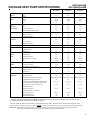
PACKAGE HEAT PUMP SPECIFICATIONS
GPH1342H41AB
GPH13[48-60]H41BB
GPH1342H41**
GPH1348H41**
GPH1360H41**
COOLING
COOLING CAPACITY, BTUH
40,500
46,000
57,500
CAPACITY
SEER
47°/43°F
13.00
13.00
13.00
HEATING
RATING
38,000
44,500
54,400
35°/33°F
30,000
33,000
39,000
17°/15°F
21,800
26,000
32,000
7.8
7.7
7.7
208/230-60-1
208/230-60-1
208/230-60-1
HSPF
UNIT
VOLTAGE (NAMEPLATE)
ELECTRICAL
AMPS
22.2
24.17
33.6
SPECIFICATION
MIN CIRCUIT AMPACITY
26.6
29.2
40.2
40
45
60
SCROLL
SCROLL
SCROLL
RATED LOAD AMPS
17.9
19.9
26.4
LOCKED ROTOR AMPS
112
109
134
CONDENSER
HORSEPOWER
1/6
1/6
1/4
FAN MOTOR
RPM
1075
1075
1075
FULL LOAD AMPS
1.4
1.4
1.4
LOCKED ROTOR AMPS
2.9
2.9
2.9
MAX OVERCURRENT PROTECTION(2)
COMPRESSOR
TYPE
CONDENSER FAN
BLADE DIAMETER (INCHES) / # OF BLADES
22 / 4
22 / 4
22 / 4
CONDENSER
FACE AREA (SQ. FT.)
17
19.1
19.1
COIL
NUMBER OF ROWS
1
2
2
FINS PER INCH
24
16
16
EVAPORATOR
HORSEPOWER - NO. OF SPEEDS
1/2 - 3
1/2 - 3
3/4 -3
BLOWER
FULL LOAD AMPS
2.87
2.87
5.8
MOTOR
LOCKED ROTOR AMPS
4.9
4.9
8.0
MEDIUM
HIGH
MEDIUM
MOTOR SPEED TAP - COOLING
RPM
1,075
1,075
1,075
EVAPORATOR
DIAMETER X WIDTH (INCHES)
10 x 8
10 x 8
11 x 8
BLOWER
RATED SCFM COOLING
1,410
1,585
1,850
MAX EXTERNAL STATIC PRESS ("w.c.)
0.5
0.5
0.5
EVAPORATOR
FACE AREA (SQ. FT.)
6.2
6.2
7.0
COIL
NUMBER OF ROWS
4
4
4
FINS PER INCH
14
14
14
(2) 20 x 20 x 1
(2) 20 x 20 x 1
(2) 20 x 25 x 1
GENERAL
FILTER SIZE (SQ. FT.)
INFORMATION
DRAIN SIZE (INCHES)
EXPANSION DEVICE (INDOOR / OUTDOOR)
REFRIGERANT CHARGE R-410A (OZS.)
POWER SUPPLY CONDUIT KNOCKOUT SIZE (INCHES)
LOW VOLTAGE CONDUIT KNOCKOUT SIZE (INCHES)
PRESSURE SWITCH - OPENS / CLOSES PSIG
3/4"
3/4"
3/4"
ORIFICE (0.068 / 0.065)
ORIFICE (0.076 / 0.067)
ORIFICE (0.088 / 0.076)
140
170
175
3/4, 1, 1-1/4
3/4, 1, 1-1/4
3/4, 1, 1-1/4
1/2
1/2
1/2
7 / 25
7 / 25
7 / 25
22 / 50
22 / 50
22 / 50
660 / 420
660 / 420
660 / 420
LO PRESSURE SWITCH
OPENS / CLOSES PSIG
HI PRESSURE SWITCH - OPENS PSIG
OPENS / CLOSES PSIG
SHIPPING WEIGHT (LBS.)
385
415
415
OPERATING WEIGHT (LBS.)
375
405
405
(2)
*
Maximum Overcurrent Protection Device: MUST use Time Delay Fuse or HACR type Circuit Breaker of the same size as noted.
Calculated external filter size based on air velocity of 300 ft/min.
Wire size should be determined in accordance with National Electrical Codes. Extensive wire runs will require larger wire sizes.
Unit specifications are subject to change without notice. ALWAYS refer to the units serial plate for the most up-to-date general and electrical information.
IMPORTANT: While this data is presented as a guide, it is important to electrically connect the unit and properly size wires and fuses/circuit breakers
in accordance with the National Electrical Code and/or all local codes. Data shown is w/o electric heaters.
9
ACCESSORIES
Part Number
Description
OT18-60A
Outdoor Thermostat Kit w/Lockout Stat
OT/EHR18-60
Emergency Heat Relay Kit
HKR
Electric Heat Kit
PCCP101-103
Roof Curb
PCP101-103
Downflow Plenum Kit
PCP101-103R8
Downflow Plenum Kit w/ R-8 Insulation
GPCED101-103
Downflow Economizer for GPC-(H) A/C - To Be Used With PCP101-103
GPHED101-103
Downflow Economizer for GPH-(H) Heat Pump - To Be Used With PCP101-103
GPCEH101-103
Horizontal Economizer for GPC-(H) A/C
GPHEH101-103
Horizontal Economizer for GPH-(H) Heat Pump
PCMD101-103
Manual Damper - To Be Used With PCP101-103
PCMDM101-103
Motorized Damper - To Be Used With PCP101-103
GPHMD101-103
Manual Damper for Horizontal Applications
SQRPCH101
Square to Round Adapters 16"&14"
SQRPCH102-103
Square to Round Adapters 18"&14"
SQRPC101
Square to Round Adapter - For Use With PCCP101-103 Curb 16" Rounds
SQRPC102-103
Square to Round Adapter For Use With PCCP101-103 Curb 18" Rounds
PCFR101-103
External Horizontal Filter Rack
PCEF101-103
Elbow & Flashing w/ R-8 Liner
CDK36
Flush Mount Concentric Duct Kit
CDK36515
Flush Mount Concentric Duct Kit w/ Filter
CDK36530
Step Down Concentric Duct Kit
CDK36535
Step Down Concentric Duct Kit w/ Filter
CDK4872
Flush Mount Concentric Duct Kit
CDK4872515
Flush Mount Concentric Duct Kit w/ Filter
CDK4872530
Step Down Concentric Duct Kit
CDK4872535
Step Down Concentric Duct Kit w/ Filter
10
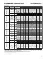
GPH13[24-60]H41**
BLOWER PERFORMANCE DATA
Speed
LOW
230
MED
230
HIGH
230
LOW
230
GPH1360H41**
GPH1348H41**
GPH1342H41**
GPH1336H41**
GPH1330H41**
Model
GPH1324H41**
Dry Coil Data
Volts
CFM
WATTS
CFM
WATTS
CFM
WATTS
CFM
E.S.P (In. of H2 O)
0.1
680
0.2
640
0.3
590
0.4
555
0.5
505
0.6
440
0.7
340
0.8
-
155
895
230
1,185
150
855
220
1,130
145
815
215
1,070
140
755
205
1,010
130
700
195
930
120
630
180
850
110
545
170
760
390
145
650
350
340
325
310
295
280
265
245
1,150
1,080
1,025
975
925
845
-
-
WATTS
340
330
315
305
295
280
-
-
CFM
WATTS
1,335
425
1,275
415
1,205
400
1,135
385
1,075
370
985
350
910
330
845
310
MED
230
HIGH
230
CFM
WATTS
1,435
485
1,355
465
1,290
455
1,210
435
1,130
415
1,040
400
960
385
885
370
LOW
230
CFM
WATTS
1,180
1,125
1,075
1,020
955
875
655
-
335
325
315
305
295
275
240
-
MED
230
CFM
1,350
435
1,280
420
1,205
405
1,130
385
1,050
375
985
350
910
330
845
310
HIGH
230
1,450
1,370
1,290
1,205
1,130
1,040
960
885
LOW
230
495
1,425
480
1,410
465
1,355
440
1,310
425
1,245
400
1,170
385
1,080
370
-
450
445
430
420
405
390
370
-
MED
230
1,620
1,595
1,545
1,485
1,425
1,345
1,250
1,160
HIGH
230
550
1,945
540
1,935
525
1,875
510
1,800
495
1,730
475
1,635
450
1,535
425
1,440
765
755
735
715
695
670
640
615
LOW
230
CFM
1,425
1,410
1,355
1,310
1,245
1,170
1,080
-
WATTS
MED
230
CFM
450
1,720
445
1,660
430
1,585
420
1,520
405
1,460
390
1,365
370
1,270
-
HIGH
230
WATTS
CFM
560
2,110
555
2,060
540
1,980
530
1,895
520
1,795
490
1,705
470
1,590
1,500
WATTS
CFM
785
780
765
745
720
705
665
625
1,775
1,635
1,645
1,515
1,510
1,450
1,430
1,400
395
1,845
490
420
1,790
505
435
1,715
520
445
1,685
535
455
1,590
550
465
1,580
560
470
1,530
570
475
1,500
575
2,025
575
1,900
595
1,840
620
1,780
630
1,725
645
1,650
655
1,620
660
1,580
670
T1
230
T2/T3
230
T4/T5
230
WATTS
CFM
WATTS
CFM
WATTS
CFM
WATTS
CFM
WATTS
WATTS
CFM
WATTS
CFM
WATTS
NOTES:
1.
2.
3.
4.
Data shown is Dry Coil. Wet Coil Pressure Drop is approximate.
0.1" H2O, for 2 row indoor coil; 0.2” H2O, for 3 row indoor coil; and 0.3” H2O, for 4 row indoor coil.
Data shown does not include filter pressure drop, approx. 0.08” H2O.
Reduce airflow by 2% for 208V operation.
11
12
10
20
30
40
50
60
70
30
80
90
100
40
50
60
700
600 CFM
90
100
2000
2200
2400 CFM
1800
1600
1400
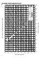
OUTPUT BTU/HR x 1000
80
1200
1100
1000
900
70
800
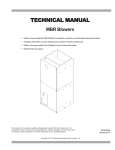
FORMULAS
110
120
130
140
BTU OUTPUT = CFM x 1.08 x RISE
BTU OUTPUT
RISE =
÷ CFM
1.08
BTU OUTPUT vs TEMPERATURE RISE CHART
150
BLOWER PERFORMANCE DATA
TEMPERATURE RISE
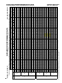
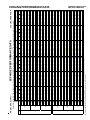
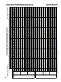
EXPANDED PERFORMANCE DATA
23.7
0.64
16
1.73
7.3
257
118
22.5
0.61
16
1.70
7.2
252
116
24.6
0.81
19
1.76
7.5
263
120
23.9
0.78
20
1.74
7.4
260
119
22.7
0.74
20
1.72
7.3
255
117
MBh
22.8
S/T
0.76
Delta T 18
KW
1.69
AMPS 7.2
HI PR 239
LO PR 111
MBh
21.7
S/T
0.73
Delta T 19
KW
1.67
AMPS 7.1
HI PR 234
LO PR 109
MBh
23.9
S/T
0.91
Delta T 20
KW
1.72
AMPS 7.3
HI PR 244
LO PR 113
MBh
23.2
S/T
0.87
Delta T 21
KW
1.71
AMPS 7.2
HI PR 242
LO PR 112
MBh
22.1
S/T
0.83
Delta T 22
KW
1.68
AMPS 7.1
HI PR 237
LO PR 110
875
770
980
875
770
24.6
0.56
17
1.77
7.5
269
128
25.9
0.59
16
1.80
7.6
275
130
26.7
0.62
15
1.81
7.7
277
131
24.6
0.42
12
1.75
7.4
266
126
25.9
0.44
12
1.78
7.5
272
129
7.6
275
130
26.4
0.36
11
1.82
7.7
281
136
27.8
0.38
11
1.85
7.8
286
139
28.6
0.40
11
1.87
7.9
289
140
-
-
-
21.5
0.86
22
1.81
7.6
266
116
22.7
0.90
21
1.83
7.7
271
118
23.4
0.94
21
1.85
7.8
274
120
21.2
0.76
19
1.79
7.6
263
115
22.3
0.79
19
1.82
7.7
268
117
7.7
271
118
22.2
0.77
20
1.84
7.8
286
123
23.4
0.81
20
1.87
7.9
292
126
24.1
0.84
19
1.89
8.0
295
127
22.0
0.63
17
1.83
7.7
283
122
23.1
0.66
16
1.86
7.8
289
125
7.9
292
126
24.0
0.58
17
1.90
8.0
302
135
25.3
0.61
16
1.93
8.1
308
138
26.0
0.64
16
1.95
8.2
311
139
24.1
0.44
13
1.89
7.9
299
133
25.3
0.46
12
1.92
8.1
305
136
8.1
308
137
25.8
0.38
12
1.96
8.3
315
144
27.1
0.39
11
1.99
8.4
321
146
27.9
0.41
11
2.01
8.5
325
148
-
-
-
21.0
0.88
22
1.92
8.2
302
121
22.1
0.92
21
1.95
8.3
308
123
22.8
0.97
21
1.96
8.4
311
124
20.7
0.78
19
1.90
8.1
299
119
21.8
0.81
19
1.93
8.3
305
122
8.3
308
123
21.7
0.79
20
1.96
8.4
325
128
22.8
0.83
20
1.99
8.5
332
131
23.5
0.87
19
2.00
8.6
335
132
21.4
0.65
17
1.94
8.3
322
127
22.6
0.68
16
1.97
8.4
328
130
8.5
332
131
23.4
0.60
17
2.02
8.6
343
140
24.7
0.63
16
2.05
8.8
350
143
25.4
0.66
16
2.07
8.8
354
144
23.5
0.45
13
2.00
8.5
340
139
24.7
0.47
12
2.03
8.7
347
141
8.8
350
143
-
-
-
25.2
0.39
12
2.08
8.9
358
149
26.5
0.40
11
2.12
9.0
365
152
27.3
0.42
11
2.13
9.1
369
154
* Entering Indoor Dry Bulb Temperature
NOTE: Shaded area is ACCA (TVA) conditions
High and low pressures are measured at the liquid and suction access fittings.
75
70
7.4
260
119
7.2
242
112
AMPS
HI PR
LO PR
20.5
0.91
22
2.01
8.7
344
127
21.6
0.95
22
2.05
8.8
351
129
22.2
1.00
21
2.06
8.9
355
131
20.2
0.80
19
2.00
8.6
341
125
21.2
0.84
19
2.03
8.8
348
128
8.8
351
129
21.1
0.82
21
2.06
8.9
370
135
22.2
0.85
20
2.09
9.0
378
138
22.9
0.89
19
2.11
9.1
382
139
20.9
0.67
17
2.04
8.8
367
133
22.0
0.70
16
2.07
8.9
374
136
9.0
378
137
22.9
0.62
17
2.12
9.1
391
147
24.1
0.65
16
2.16
9.3
399
150
24.8
0.68
16
2.17
9.4
403
152
22.9
0.46
13
2.10
9.1
387
146
24.1
0.49
12
2.14
9.2
395
149
9.3
399
150
24.5
0.40
12
2.19
9.4
408
157
25.8
0.42
11
2.23
9.6
416
160
26.6
0.44
11
2.25
9.7
420
161
-
-
-
19.5
0.95
22
2.10
9.2
387
133
20.5
0.99
21
2.13
9.3
395
135
21.1
1.00
20
2.15
9.4
399
137
19.2
0.83
19
2.08
9.1
383
131
20.2
0.87
18
2.11
9.3
391
134
9.3
395
135
20.1
0.85
20
2.14
9.4
417
141
21.1
0.88
20
2.18
9.5
425
144
21.8
0.93
19
2.19
9.6
429
146
19.9
0.70
17
2.12
9.3
412
140
20.9
0.73
16
2.16
9.5
421
143
9.5
425
144
21.7
0.64
17
2.21
9.7
440
154
22.9
0.67
16
2.25
9.8
449
157
23.6
0.70
16
2.27
9.9
453
159
21.8
0.48
13
2.19
9.6
436
153
22.9
0.50
12
2.23
9.7
444
156
9.8
449
157
23.3
0.41
11
2.28
10.0
459
164
24.5
0.43
11
2.32
10.2
468
168
25.3
0.45
11
2.34
10.2
473
169
-
-
-
18.1
0.96
21
2.17
9.7
428
137
19.0
1.00
20
2.20
9.8
437
140
19.6
1.00
18
2.22
9.9
441
142
17.8
0.84
18
2.15
9.6
423
136
18.7
0.88
17
2.18
9.7
432
139
9.8
436
140
18.6
0.85
19
2.21
9.9
460
146
19.6
0.89
18
2.25
10.0
470
149
20.2
0.94
18
2.27
10.1
474
151
18.4
0.70
15
2.20
9.8
456
145
19.4
0.73
15
2.23
10.0
465
148
10.0
470
149
20.1
0.65
16
2.29
10.2
486
159
21.2
0.68
15
2.32
10.3
496
163
21.8
0.71
14
2.34
10.4
501
164
20.2
0.49
12
2.27
10.1
481
158
21.2
0.51
11
2.31
10.3
491
161
10.3
496
163
21.6
0.42
11
2.36
10.5
507
170
22.7
0.43
10
2.40
10.7
517
173
23.4
0.46
10
2.42
10.8
523
175
-
-
-
71
-
COOLING OPERATION
Design Subcooling, 12±3 °F @ the liquid access fitting connection AHRI 95 test conditions. Design Superheat 8±3 °F @ the compressor suction access fitting connection.
Outdoor Ambient Temperature
65
75
85
95
105
115
Entering Indoor Wet Bulb Temperature
IDB* Airflow
59
63
67
71
59
63
67
71
59
63
67
71
59
63
67
71
59
63
67
71
59
63
67
MBh
23.5 24.4 26.7
23.0 23.8 26.1
22.4 23.2 25.5
21.9
22.7
24.8
20.8 21.5 23.6
19.3 20.0 21.9
S/T
0.80 0.67 0.46
0.83 0.69 0.48
0.85 0.71 0.49
0.88
0.73
0.51
0.91 0.76 0.53
0.92 0.77 0.53
Delta T 18
15
12
18
15
12
18
16
12
18
16
12
18
15
12
17
14
11
980
KW
1.71 1.74 1.80
1.83 1.87 1.93
1.95 1.99 2.05
2.05
2.09
2.16
2.13 2.18 2.25
2.20 2.25 2.32
MODEL: GPH1324H41**
COOLING PERFORMANCE DATA
GPH1324H41**
13
14
EXPANDED PERFORMANCE DATA
24.8
1.00
23
1.75
7.4
249
115
24.0
1.00
25
1.73
7.4
246
114
MBh
S/T
Delta T
KW
AMPS
HI PR
LO PR
MBh
S/T
Delta T
KW
AMPS
HI PR
LO PR
770
980
875
22.5
0.91
24
1.69
7.2
239
111
MBh
S/T
Delta T
KW
AMPS
HI PR
LO PR
875
24.5
0.96
25
1.77
7.5
265
122
25.2
1.00
24
1.78
7.6
268
123
22.9
0.86
23
1.73
7.3
257
118
24.1
0.89
23
1.76
7.5
263
120
25.7
0.87
23
1.82
7.7
280
133
26.4
0.91
23
1.84
7.8
283
134
24.5
0.70
20
1.78
7.5
272
129
25.8
0.73
20
1.81
7.7
277
131
27.4
0.71
20
1.88
8.0
292
141
28.2
0.74
20
1.90
8.0
295
143
26.2
0.52
16
1.84
7.8
283
137
27.6
0.54
16
1.87
7.9
289
140
23.5
1.00
25
1.86
7.9
277
121
24.2
1.00
23
1.88
7.9
279
122
21.9
0.95
25
1.82
7.7
268
117
23.1
0.99
24
1.85
7.8
274
120
23.9
1.00
25
1.90
8.0
298
129
24.7
1.00
23
1.92
8.1
301
130
22.4
0.89
24
1.86
7.8
289
125
23.6
0.93
23
1.89
8.0
295
127
25.1
0.90
24
1.96
8.3
314
140
25.8
0.95
23
1.98
8.3
317
142
23.9
0.72
21
1.92
8.1
305
136
25.2
0.75
20
1.95
8.2
311
139
26.8
0.73
21
2.03
8.5
328
149
27.6
0.77
20
2.04
8.6
331
151
25.6
0.54
16
1.98
8.3
318
145
26.9
0.56
16
2.01
8.5
325
148
22.9
1.00
24
1.98
8.5
315
126
23.6
1.00
22
1.99
8.5
318
127
21.4
0.97
25
1.93
8.3
305
122
22.5
1.00
24
1.96
8.4
311
124
MBh
22.8 23.3 24.4 26.0 22.3 22.7 23.8 25.4 21.8
S/T
0.96 0.92 0.83 0.68 0.99 0.96 0.86 0.70 1.00
Delta T 26
26
24
21
26
26
25
21
26
770
KW
1.71 1.74 1.80 1.85 1.83 1.87 1.93 1.99 1.95
AMPS 7.2
7.4
7.6
7.8
7.7
7.9
8.1
8.4
8.3
HI PR 242
260
275
286
271
292
308
321
308
LO PR 112
119
130
139
118
126
137
146
123
* Entering Indoor Dry Bulb Temperature
NOTE: Shaded area is AHRI
High and low pressures are measured at the liquid and suction access fittings.
85
80
23.6
0.95
24
1.72
7.3
244
113
MBh
S/T
Delta T
KW
AMPS
HI PR
LO PR
24.5
0.92
24
2.08
8.9
357
146
25.2
0.97
23
2.10
9.0
361
147
23.4
0.74
21
2.03
8.7
347
141
24.6
0.77
20
2.07
8.8
354
144
26.1
0.75
21
2.15
9.2
373
155
26.9
0.79
20
2.17
9.3
377
157
25.0
0.55
17
2.10
9.0
362
151
26.3
0.58
16
2.14
9.1
369
154
22.2 23.3 24.8
0.98 0.89 0.72
26
25
21
1.99 2.05 2.12
8.5
8.8
9.0
332
350
365
131
143
152
Rating Conditions
23.4
1.00
25
2.02
8.6
339
134
24.1
1.00
23
2.04
8.7
342
135
21.9
0.91
24
1.97
8.4
328
130
23.0
0.95
23
2.00
8.6
335
132
21.2
1.00
25
2.05
8.8
351
129
22.4
1.00
24
2.08
9.0
358
132
23.0
1.00
22
2.10
9.0
362
133
20.9
1.00
25
2.03
8.8
348
128
22.0
1.00
23
2.06
8.9
355
131
21.7
1.00
26
2.09
9.0
378
137
22.8
1.00
24
2.12
9.2
386
140
23.5
1.00
22
2.14
9.2
389
142
21.3
0.94
24
2.07
8.9
374
136
22.5
0.98
23
2.11
9.1
382
139
25.5
0.77
21
2.26
9.8
425
163
26.2
0.81
20
2.28
9.8
429
165
24.4
0.57
17
2.21
9.5
412
158
25.7
0.60
16
2.25
9.7
420
162
21.2
1.00
22
2.17
9.5
403
138
21.9
1.00
21
2.18
9.6
407
140
19.8
1.04
25
2.11
9.3
391
134
20.9
1.00
22
2.15
9.4
399
137
21.7
1.00
23
2.21
9.7
434
147
22.3
1.00
21
2.23
9.8
438
149
20.3
0.97
24
2.16
9.5
421
143
21.3
1.00
22
2.19
9.6
429
146
22.7
0.99
24
2.28
10.0
458
161
23.4
1.00
22
2.30
10.1
463
162
21.7
0.79
21
2.23
9.7
444
156
22.8
0.83
20
2.27
9.9
453
159
24.2
0.80
20
2.36
10.3
478
171
24.9
0.84
20
2.38
10.4
482
173
23.2
0.59
16
2.30
10.1
464
166
24.4
0.62
16
2.34
10.2
473
169
19.7
1.00
21
2.24
10.0
445
143
20.3
1.00
19
2.26
10.1
450
144
18.4
1.05
23
2.18
9.7
432
139
19.3
1.00
20
2.22
9.9
441
142
20.1
1.00
21
2.29
10.2
479
152
20.7
1.00
19
2.31
10.3
484
154
18.8
0.98
22
2.23
10.0
465
148
19.8
1.00
21
2.27
10.1
474
151
21.0
1.00
22
2.36
10.5
506
166
21.6
1.00
20
2.38
10.6
511
168
20.1
0.80
19
2.31
10.3
491
161
21.1
0.84
19
2.34
10.4
501
164
22.7
24.2 20.2 20.6 21.6 23.0 18.7 19.1 20.0
0.91
0.74 1.00 1.00 0.95 0.77 1.00 1.00 0.96
25
21
24
25
24
21
22
23
23
2.16
2.23 2.13 2.18 2.25 2.32 2.20 2.25 2.32
9.3
9.6
9.3
9.5
9.8
10.2
9.8
10.0 10.3
399
416
395
425
449
468
436
470
496
150
160
135
144
157
168
140
149
163
KW = Total system power
AMPS: Unit amps (comp.+ evaporator + condenser fan motors)
23.9
0.95
24
2.19
9.4
407
153
24.6
1.00
23
2.21
9.5
411
155
24.0
0.80
20
2.18
9.4
403
152
22.8
0.76
21
2.14
9.2
395
149
21.3
0.78
20
2.40
10.7
517
173
22.4
0.81
19
2.44
10.9
528
177
23.1
0.85
18
2.46
11.0
533
179
21.4
0.60
15
2.38
10.6
512
172
22.6
0.62
15
2.42
10.8
523
175
71
23.3
0.65
14
2.44
10.9
528
177
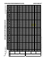
COOLING OPERATION
Design Subcooling, 12±3 °F @ the liquid access fitting connection AHRI 95 test conditions. Design Superheat 8±3 °F @ the compressor suction access fitting connection.
Outdoor Ambient Temperature
65
75
85
95
105
115
Entering Indoor Wet Bulb Temperature
IDB* Airflow
59
63
67
71
59
63
67
71
59
63
67
71
59
63
67
71
59
63
67
71
59
63
67
MBh
24.3 24.9 26.6 28.4 23.8 24.3 26.0 27.7 23.2 23.7 25.3 27.1 22.6
23.1
24.7
26.4 21.5 22.0 23.5 25.1 19.9 20.4 21.8
S/T
1.00 0.94 0.76 0.57 1.00 1.00 0.79 0.59 1.00 1.00 0.81 0.61 1.00
1.00
0.84
0.63 1.00 1.00 0.87 0.65 1.00 1.00 0.88
Delta T 23
22
19
15
22
23
19
15
22
22
19
15
21
22
19
16
20
21
19
15
19
19
18
980
KW
1.73 1.77 1.82 1.88 1.86 1.90 1.96 2.03 1.98 2.02 2.08 2.15 2.08
2.12
2.19
2.26 2.17 2.21 2.28 2.36 2.24 2.29 2.36
AMPS 7.4
7.5
7.7
8.0
7.9
8.0
8.3
8.5
8.5
8.6
8.9
9.2
9.0
9.2
9.4
9.8
9.5
9.7
10.0 10.3 10.0 10.2 10.5
HI PR 246
265
280
292
277
298
314
328
315
339
357
373
358
386
407
425
403
434
458
478
445
479
506
LO PR 114
122
133
141
121
129
140
149
126
134
146
155
132
140
153
163
138
147
161
171
143
152
166
MODEL: GPH1324H41**
COOLING PERFORMANCE DATA
GPH1324H41**
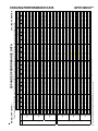
EXPANDED PERFORMANCE DATA
28.9
0.81
18
2.09
8.9
268
120
28.1
0.77
19
2.07
8.8
265
119
MBh
28.1
S/T
0.91
Delta T 20
KW
2.04
AMPS 8.7
HI PR 249
LO PR 113
MBh
27.3
S/T
0.86
Delta T 21
KW
2.03
AMPS 8.7
HI PR 247
LO PR 112
920
1180
1050
25.7
0.61
16
2.01
8.6
255
114
MBh
24.8
S/T
0.73
Delta T 18
KW
1.97
AMPS 8.4
HI PR 237
LO PR 107
1050
30.4
0.58
16
2.13
9.1
280
130
31.3
0.61
15
2.15
9.1
283
131
28.1
0.42
12
2.07
8.8
269
125
30.5
0.44
12
2.12
9.0
277
129
32.6
0.38
11
2.20
9.4
292
138
33.6
0.39
10
2.22
9.4
295
140
-
-
26.6
0.90
21
2.18
9.3
277
118
27.4
0.94
20
2.20
9.3
280
119
24.2
0.76
18
2.11
9.0
266
113
26.2
0.79
18
2.16
9.2
274
117
27.4
0.80
19
2.22
9.4
298
126
28.3
0.84
18
2.24
9.5
301
127
25.1
0.63
16
2.15
9.1
286
121
27.2
0.66
16
2.21
9.4
295
124
29.7
0.61
16
2.29
9.7
315
137
30.6
0.64
15
2.31
9.8
318
139
27.5
0.44
12
2.22
9.4
302
132
29.8
0.46
12
2.27
9.6
311
136
31.9
0.39
11
2.36
10.0
328
146
32.8
0.41
10
2.38
10.1
331
148
-
-
26.0
0.92
21
2.31
9.9
315
123
26.8
0.96
20
2.33
10.0
318
124
23.6
0.78
18
2.24
9.6
302
118
25.6
0.81
18
2.29
9.9
312
121
MBh
25.2 25.9 28.1 30.1 24.6 25.3 27.4 29.4 24.0
S/T
0.83 0.74 0.56 0.36 0.86 0.77 0.58 0.38 0.89
Delta T 21
19
16
11
21
20
16
11
21
920
KW
1.98 2.02 2.08 2.15 2.13 2.17 2.24 2.31 2.26
AMPS 8.5
8.6
8.9
9.1
9.0
9.2
9.5
9.8
9.7
HI PR 239
257
272
284
268
289
305
318
305
LO PR 108
115
126
134
115
122
133
142
119
* Entering Indoor Dry Bulb Temperature
NOTE: Shaded area is ACCA
High and low pressures are measured at the liquid and suction access fittings.
75
70
27.8
0.63
15
2.05
8.8
263
118
MBh
26.8
S/T
0.76
Delta T 18
KW
2.01
AMPS 8.6
HI PR 244
LO PR 111
29.0
0.62
16
2.43
10.4
358
143
29.9
0.65
15
2.45
10.5
361
144
26.8
0.45
12
2.36
10.1
343
137
29.0
0.47
12
2.41
10.4
354
141
31.1
0.40
11
2.51
10.8
373
152
32.0
0.42
10
2.53
10.9
377
153
-
-
24.7 26.8 28.7
0.79 0.60 0.39
20
16
11
2.30 2.37 2.45
9.9
10.2 10.5
329
347
362
127
138
147
(TVA) conditions
26.8
0.82
19
2.36
10.1
339
131
27.6
0.86
19
2.38
10.2
342
132
24.5
0.65
16
2.28
9.8
325
125
26.5
0.67
16
2.34
10.1
335
129
23.4
0.91
21
2.37
10.3
348
125
25.4
0.95
21
2.43
10.5
358
129
26.1
0.99
20
2.45
10.6
362
130
23.0
0.80
18
2.35
10.2
344
124
25.0
0.83
18
2.41
10.4
355
128
26.9
0.89
19
2.50
10.8
390
139
26.1
0.85
19
2.48
10.8
386
137
24.1
0.82
20
2.42
10.5
374
133
23.9
0.67
16
2.40
10.4
370
132
25.9
0.70
16
2.46
10.7
382
136
26.1
0.62
16
2.50
10.8
395
145
28.3
0.64
16
2.56
11.1
407
150
29.1
0.67
15
2.58
11.2
411
151
26.2
0.47
12
2.48
10.7
391
144
28.3
0.48
12
2.54
11.0
403
148
28.0
0.40
11
2.58
11.2
412
155
30.4
0.41
11
2.64
11.4
425
159
31.3
0.43
11
2.66
11.5
429
161
-
-
22.3
0.95
21
2.47
10.9
391
131
24.1
0.98
21
2.53
11.1
403
135
24.8
1.00
19
2.55
11.2
407
136
21.9
0.83
18
2.45
10.8
387
130
23.7
0.87
18
2.51
11.0
399
134
22.9
0.85
19
2.52
11.1
421
139
24.8
0.88
19
2.58
11.4
434
144
25.6
0.92
18
2.60
11.5
438
145
22.7
0.70
16
2.50
11.0
417
138
24.6
0.72
16
2.56
11.3
430
142
24.8
0.64
16
2.60
11.4
445
152
26.9
0.67
16
2.66
11.7
458
157
27.7
0.70
15
2.69
11.8
463
158
24.9
0.48
12
2.58
11.3
440
151
26.9
0.50
12
2.64
11.6
454
155
26.6
0.41
11
2.68
11.8
464
162
28.8
0.43
11
2.75
12.1
478
167
29.7
0.45
10
2.77
12.2
483
169
-
-
20.6
0.96
20
2.55
11.4
432
136
22.3
0.99
19
2.61
11.7
446
140
23.0
1.00
18
2.63
11.8
450
141
20.3
0.84
17
2.53
11.3
428
134
22.0
0.87
17
2.59
11.6
441
138
21.2
0.86
18
2.60
11.7
465
144
23.0
0.89
18
2.67
12.0
480
149
23.7
0.93
17
2.69
12.1
484
150
21.0
0.70
15
2.58
11.6
460
143
22.8
0.73
15
2.65
11.9
475
147
23.0
0.65
15
2.69
12.0
491
157
24.9
0.67
15
2.76
12.3
506
162
25.6
0.70
14
2.78
12.4
511
164
23.0
0.49
11
2.66
11.9
486
156
24.9
0.50
11
2.73
12.2
501
161
24.7
0.42
10
2.78
12.4
512
168
26.7
0.43
10
2.85
12.7
528
173
27.5
0.45
10
2.87
12.9
533
175
-
-
71
-
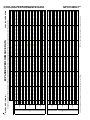
COOLING OPERATION
Design Subcooling, 12±3 °F @ the liquid access fitting connection AHRI 95 test conditions. Design Superheat 8±3 °F @ the compressor suction access fitting connection.
Outdoor Ambient Temperature
65
75
85
95
105
115
Entering Indoor Wet Bulb Temperature
IDB* Airflow
59
63
67
71
59
63
67
71
59
63
67
71
59
63
67
71
59
63
67
71
59
63
67
MBh
27.6 28.6 31.4
27.0 28.0 30.7
26.3 27.3 29.9
25.7
26.6
29.2
24.4 25.3 27.7
22.6 23.4 25.7
S/T
0.80 0.67 0.46
0.83 0.69 0.48
0.85 0.71 0.49
0.87
0.73
0.51
0.91 0.76 0.52
0.91 0.76 0.53
Delta T 17
15
11
17
15
11
17
15
11
18
15
11
17
15
11
16
14
11
1180
KW
2.03 2.07 2.13
2.18 2.22 2.29
2.31 2.36 2.43
2.43
2.48
2.56
2.53 2.58 2.66
2.61 2.67 2.75
AMPS 8.7
8.8
9.1
9.3
9.4
9.7
9.9
10.1 10.4
10.5
10.8
11.1
11.1 11.4 11.7
11.7 12.0 12.3
HI PR 247
265
280
277
298
314
315
339
358
358
386
407
403
434
458
446
479
506
LO PR 112
119
130
118
126
137
123
131
143
129
137
150
135
144
157
140
149
162
MODEL: GPH1330H41**
COOLING PERFORMANCE DATA
GPH1330H41**
15
16
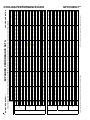
EXPANDED PERFORMANCE DATA
29.7
1.00
23
2.12
9.0
273
123
28.8
0.96
24
2.10
9.0
271
121
MBh
29.1
S/T
1.00
Delta T 23
KW
2.08
AMPS 8.9
HI PR 254
LO PR 115
MBh
28.3
S/T
0.99
Delta T 25
KW
2.06
AMPS 8.8
HI PR 252
LO PR 114
920
1180
1050
26.2
0.86
22
2.04
8.7
260
117
MBh
25.6
S/T
0.91
Delta T 23
KW
2.00
AMPS 8.5
HI PR 242
LO PR 110
1050
30.2
0.86
23
2.17
9.2
286
132
31.1
0.91
22
2.18
9.3
289
134
28.0
0.70
19
2.10
8.9
275
127
30.3
0.72
19
2.15
9.2
283
131
32.2
0.70
20
2.23
9.5
298
141
33.1
0.74
19
2.25
9.6
301
142
29.9
0.52
16
2.16
9.2
286
135
32.4
0.54
15
2.22
9.4
295
140
27.6
1.00
24
2.21
9.4
282
120
28.4
1.00
22
2.23
9.5
285
122
25.0
0.95
24
2.14
9.1
271
116
27.1
0.98
23
2.20
9.3
280
119
28.1
0.99
24
2.26
9.6
304
128
29.0
1.00
23
2.28
9.7
307
129
25.6
0.89
23
2.19
9.3
292
123
27.7
0.92
22
2.24
9.5
301
127
29.5
0.90
23
2.33
9.9
321
140
30.3
0.94
22
2.35
9.9
324
141
27.3
0.72
20
2.26
9.6
308
134
29.6
0.75
19
2.31
9.8
318
139
31.4
0.73
20
2.40
10.2
335
149
32.4
0.76
19
2.42
10.3
338
151
29.2
0.54
16
2.33
9.9
321
143
31.7
0.56
16
2.38
10.1
331
148
26.9
1.00
24
2.35
10.1
321
125
27.7
1.00
22
2.37
10.2
324
126
24.4
0.97
24
2.27
9.8
308
120
26.5
1.00
23
2.33
10.0
318
124
MBh
26.1 26.6 27.8 29.7 25.5 26.0 27.2 29.0 24.9
S/T
0.96 0.92 0.83 0.68 0.99 0.96 0.86 0.70 1.00
Delta T 25
25
23
20
25
25
23
20
25
920
KW
2.01 2.05 2.12 2.18 2.16 2.21 2.27 2.35 2.29
AMPS 8.6
8.8
9.0
9.3
9.2
9.4
9.6
9.9
9.9
HI PR 244
263
277
289
274
295
311
325
311
LO PR 111
118
128
137
117
124
136
145
121
* Entering Indoor Dry Bulb Temperature
NOTE: Shaded area is AHRI
High and low pressures are measured at the liquid and suction access fittings.
85
80
28.4
0.89
22
2.09
8.9
268
120
MBh
27.8
S/T
0.95
Delta T 23
KW
2.04
AMPS 8.7
HI PR 249
LO PR 113
28.8
0.92
23
2.47
10.6
365
145
29.6
0.96
22
2.49
10.7
369
147
26.7
0.74
20
2.39
10.3
350
140
28.9
0.77
19
2.45
10.5
361
144
30.7
0.75
20
2.55
11.0
381
155
31.6
0.78
19
2.57
11.1
384
156
28.5
0.55
16
2.47
10.6
366
149
30.9
0.57
16
2.53
10.9
377
153
25.3 26.5 28.3
0.98 0.89 0.72
25
24
20
2.34 2.41 2.49
10.1 10.4 10.7
335
354
369
129
141
150
Rating Conditions
27.5
1.00
24
2.40
10.3
346
133
28.3
1.00
22
2.42
10.4
349
135
25.0
0.91
23
2.32
10.0
332
128
27.1
0.94
22
2.38
10.2
342
132
24.3
1.00
24
2.41
10.4
355
128
26.3
1.00
23
2.47
10.7
366
132
27.1
1.00
21
2.49
10.8
369
133
23.8
1.00
24
2.39
10.4
351
126
25.8
1.00
23
2.45
10.6
362
130
24.7
1.00
25
2.46
10.7
382
136
26.8
1.00
23
2.52
10.9
394
140
27.6
1.00
21
2.54
11.0
398
141
24.4
0.94
23
2.44
10.6
378
134
26.4
0.97
23
2.50
10.8
390
139
29.9
0.77
20
2.68
11.6
433
163
30.8
0.81
19
2.71
11.7
438
164
27.8
0.57
16
2.60
11.3
416
156
30.1
0.59
16
2.66
11.5
429
161
25.0
1.00
22
2.57
11.3
411
138
25.7
1.00
20
2.59
11.4
416
139
22.7
1.04
24
2.49
10.9
395
132
24.5
1.00
21
2.55
11.2
407
136
25.5
1.00
22
2.62
11.6
443
147
26.2
1.00
20
2.64
11.7
447
148
23.1
0.98
23
2.54
11.2
425
141
25.1
1.00
22
2.60
11.5
438
145
26.7
0.98
23
2.71
11.9
468
160
27.5
1.00
21
2.73
12.0
472
162
24.7
0.79
20
2.62
11.5
449
154
26.8
0.82
19
2.69
11.8
463
159
28.4
0.80
20
2.80
12.3
488
171
29.3
0.84
19
2.82
12.4
493
172
26.4
0.59
16
2.71
11.9
468
164
28.6
0.62
15
2.77
12.2
483
169
23.1
1.00
20
2.66
11.9
455
143
23.8
1.00
19
2.68
12.0
459
144
21.0
1.05
22
2.57
11.5
437
137
22.7
1.00
20
2.63
11.8
450
141
23.6
1.00
21
2.71
12.2
489
152
24.3
1.00
19
2.74
12.3
494
153
21.4
0.98
21
2.62
11.8
470
146
23.2
1.00
20
2.69
12.1
484
150
24.7
0.99
21
2.80
12.5
517
166
25.4
1.00
20
2.82
12.6
522
167
22.9
0.80
18
2.71
12.1
496
159
24.8
0.83
18
2.78
12.4
511
164
25.9
27.6 23.0 23.5 24.6 26.2 21.3 21.8 22.8
0.91
0.74 1.00 1.00 0.95 0.77 1.00 1.00 0.96
24
20
23
23
23
20
21
22
22
2.54
2.62 2.51 2.56 2.64 2.73 2.59 2.65 2.73
11.0
11.3 11.0 11.3 11.6 12.0 11.6 11.9 12.2
403
420
399
430
454
473
441
475
501
148
158
134
142
155
165
138
147
161
KW = Total system power
AMPS: Unit amps (comp.+ evaporator + condenser fan motors)
28.1
0.95
23
2.60
11.3
416
153
28.9
0.99
22
2.62
11.3
420
154
28.2
0.79
20
2.58
11.2
412
151
26.0
0.76
20
2.52
10.9
399
147
24.3
0.78
19
2.82
12.6
523
171
26.3
0.81
19
2.89
13.0
539
176
27.1
0.84
18
2.92
13.1
544
178
24.5
0.60
15
2.80
12.5
517
169
26.5
0.62
14
2.87
12.9
533
175
71
27.3
0.65
14
2.89
13.0
539
176
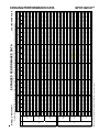
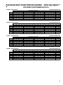
COOLING OPERATION
Design Subcooling, 12±3 °F @ the liquid access fitting connection AHRI 95 test conditions. Design Superheat 8±3 °F @ the compressor suction access fitting connection.
Outdoor Ambient Temperature
65
75
85
95
105
115
Entering Indoor Wet Bulb Temperature
IDB* Airflow
59
63
67
71
59
63
67
71
59
63
67
71
59
63
67
71
59
63
67
71
59
63
67
MBh
28.6 29.2 31.2 33.4 27.9 28.5 30.5 32.6 27.3 27.9 29.8 31.8 26.6
27.2
29.0
31.1 25.3 25.8 27.6 29.5 23.4 23.9 25.6
S/T
1.00 0.93 0.76 0.57 1.00 0.97 0.79 0.59 1.00 1.00 0.81 0.60 1.00
1.00
0.83
0.62 1.00 1.00 0.86 0.65 1.00 1.00 0.87
Delta T 22
21
18
15
22
21
19
15
21
22
19
15
21
21
19
15
20
20
19
15
18
19
17
1180
KW
2.06 2.10 2.17 2.23 2.21 2.26 2.33 2.40 2.35 2.40 2.47 2.55 2.47
2.52
2.60
2.68 2.57 2.62 2.71 2.80 2.66 2.71 2.80
AMPS 8.8
9.0
9.2
9.5
9.4
9.6
9.9
10.2 10.1 10.3 10.6 11.0 10.7
10.9
11.3
11.6 11.3 11.6 11.9 12.3 11.9 12.2 12.5
HI PR 252
271
286
298
282
304
321
335
321
346
365
381
366
394
416
433
411
443
468
488
455
489
517
LO PR 114
121
132
141
120
128
140
149
125
133
145
155
132
140
153
163
138
147
160
171
143
152
166
MODEL: GPH1330H41**
COOLING PERFORMANCE DATA
GPH1330H41**
EXPANDED PERFORMANCE DATA
34.9
0.86
20
2.63
11.2
250
111
33.9
0.82
21
2.61
11.1
247
110
MBh
S/T
Delta T
KW
AMPS
HI PR
LO PR
MBh
S/T
Delta T
KW
AMPS
HI PR
LO PR
1050
1350
1200
30.7
0.70
19
2.53
10.8
237
106
MBh
S/T
Delta T
KW
AMPS
HI PR
LO PR
1200
34.9
0.73
20
2.66
11.3
266
117
35.9
0.77
19
2.68
11.4
269
118
31.9
0.58
16
2.58
11.0
255
113
34.5
0.60
16
2.64
11.2
263
116
37.7
0.56
16
2.74
11.6
281
128
38.9
0.58
15
2.76
11.7
284
129
34.9
0.40
12
2.66
11.3
270
123
37.8
0.42
12
2.72
11.5
278
127
40.5
0.36
11
2.82
12.0
293
136
41.7
0.38
11
2.84
12.1
296
138
-
-
33.1
0.85
22
2.80
11.8
277
116
34.1
0.89
21
2.82
11.9
280
118
30.0
0.72
19
2.71
11.5
266
112
32.5
0.75
19
2.78
11.8
275
115
34.1
0.76
20
2.85
12.1
298
124
35.1
0.80
19
2.88
12.2
301
125
31.1
0.60
16
2.77
11.7
287
119
33.7
0.63
16
2.83
12.0
295
123
36.9
0.58
16
2.94
12.4
315
135
38.0
0.60
16
2.96
12.5
318
137
34.1
0.42
12
2.85
12.0
303
130
36.9
0.43
12
2.92
12.3
312
134
39.6
0.37
11
3.03
12.8
329
144
40.7
0.39
11
3.06
12.9
332
145
-
-
32.3
0.87
22
2.96
12.7
315
121
33.3
0.92
21
2.99
12.8
319
122
29.3
0.74
19
2.87
12.3
303
116
31.7
0.77
19
2.94
12.6
312
120
MBh
31.3 32.2 34.8 37.4 30.5 31.4 34.0 36.5 29.8
S/T
0.79 0.71 0.54 0.34 0.82 0.73 0.56 0.36 0.84
Delta T 22
20
16
11
22
20
17
11
22
1050
KW
2.55 2.60 2.68 2.76 2.73 2.79 2.87 2.96 2.89
AMPS 10.9 11.1 11.4 11.7 11.6 11.8 12.1 12.5 12.4
HI PR 240
258
272
284
269
290
306
319
306
LO PR 107
114
124
132
113
120
131
140
117
* Entering Indoor Dry Bulb Temperature
NOTE: Shaded area is ACCA
High and low pressures are measured at the liquid and suction access fittings.
75
70
33.3
0.72
18
2.59
11.0
245
109
MBh
S/T
Delta T
KW
AMPS
HI PR
LO PR
36.0
0.59
16
3.12
13.3
358
140
37.1
0.62
16
3.14
13.4
362
142
33.3
0.43
12
3.02
12.9
344
135
36.1
0.44
12
3.09
13.2
355
139
38.6
0.38
11
3.22
13.8
374
150
39.8
0.40
11
3.24
13.9
378
151
-
-
30.7 33.2 35.6
0.75 0.57 0.37
20
17
11
2.95 3.04 3.14
12.7 13.0 13.4
329
348
363
125
136
145
(TVA) conditions
33.2
0.78
20
3.02
13.0
339
129
34.2
0.82
19
3.05
13.1
343
130
30.4
0.62
16
2.93
12.6
326
124
32.9
0.64
16
3.00
12.9
336
127
29.1
0.87
22
3.04
13.1
349
123
31.5
0.90
22
3.11
13.4
359
127
32.4
0.94
21
3.13
13.6
363
128
28.6
0.76
19
3.01
13.0
345
122
31.0
0.79
19
3.09
13.3
356
126
33.4
0.85
19
3.20
13.8
391
137
32.4
0.81
20
3.18
13.7
387
135
29.9
0.78
20
3.10
13.4
375
131
29.6
0.64
17
3.08
13.3
371
130
32.1
0.66
16
3.15
13.6
383
134
32.4
0.59
17
3.20
13.8
396
143
35.1
0.61
16
3.27
14.1
408
148
36.2
0.64
16
3.30
14.2
412
149
32.5
0.44
13
3.17
13.7
392
142
35.2
0.46
12
3.25
14.0
404
146
34.8
0.38
12
3.30
14.2
413
152
37.7
0.39
11
3.38
14.6
426
157
38.8
0.41
11
3.41
14.7
430
159
-
-
27.6
0.90
22
3.16
13.9
392
129
29.9
0.94
21
3.23
14.2
404
133
30.8
0.98
21
3.26
14.3
408
134
27.2
0.79
19
3.13
13.7
388
128
29.4
0.82
19
3.21
14.1
400
132
28.4
0.81
20
3.22
14.1
422
137
30.8
0.84
20
3.30
14.5
435
142
31.7
0.88
19
3.33
14.6
439
143
28.2
0.66
16
3.20
14.0
418
136
30.5
0.69
16
3.28
14.4
431
140
30.8
0.61
16
3.33
14.6
446
150
33.3
0.63
16
3.41
14.9
459
155
34.4
0.66
16
3.44
15.0
464
156
30.8
0.46
12
3.30
14.4
441
148
33.4
0.48
12
3.38
14.8
455
153
33.0
0.39
11
3.43
15.0
465
160
35.8
0.41
11
3.52
15.4
479
165
36.9
0.43
11
3.55
15.5
484
166
-
-
25.6
0.91
20
3.26
14.6
433
134
27.7
0.94
20
3.34
14.9
447
138
28.6
0.99
19
3.37
15.0
451
139
25.2
0.80
18
3.24
14.4
429
132
27.3
0.83
17
3.32
14.8
442
136
26.3
0.81
19
3.33
14.9
466
142
28.5
0.84
18
3.41
15.2
481
147
29.4
0.88
18
3.44
15.4
485
148
26.1
0.67
15
3.30
14.8
461
141
28.3
0.69
15
3.39
15.1
476
145
28.5
0.62
15
3.44
15.3
492
155
30.9
0.64
15
3.52
15.7
507
160
31.8
0.67
15
3.55
15.8
513
162
28.6
0.46
12
3.41
15.2
487
154
31.0
0.48
11
3.49
15.6
502
158
30.6
0.40
11
3.55
15.8
513
165
33.2
0.41
10
3.64
16.2
529
170
34.2
0.43
10
3.67
16.4
535
172
-
-
71
-
COOLING OPERATION
Design Subcooling, 12±3 °F @ the liquid access fitting connection AHRI 95 test conditions. Design Superheat 8±3 °F @ the compressor suction access fitting connection.
Outdoor Ambient Temperature
65
75
85
95
105
115
Entering Indoor Wet Bulb Temperature
IDB* Airflow
59
63
67
71
59
63
67
71
59
63
67
71
59
63
67
71
59
63
67
71
59
63
67
MBh
34.3 35.5 38.9
33.5 34.7 38.0
32.7 33.9 37.1
31.9
33.1
36.2
30.3 31.4 34.4
28.1 29.1 31.9
S/T
0.76 0.63 0.44
0.79 0.66 0.45
0.81 0.67 0.47
0.83
0.69
0.48
0.86 0.72 0.50
0.87 0.73 0.50
Delta T 18
15
12
18
16
12
18
16
12
18
16
12
18
15
12
17
14
11
1350
KW
2.61 2.66 2.74
2.80 2.85 2.94
2.96 3.02 3.12
3.11
3.18
3.27
3.23 3.30 3.41
3.34 3.41 3.52
AMPS 11.1 11.3 11.6
11.8 12.1 12.4
12.7 13.0 13.3
13.4
13.7
14.1
14.2 14.5 14.9
14.9 15.2 15.7
HI PR 247
266
281
277
298
315
315
339
358
359
387
408
404
435
459
446
480
507
LO PR 110
117
128
116
124
135
121
129
140
127
135
148
133
142
155
138
146
160
MODEL: GPH1336H41**
COOLING PERFORMANCE DATA
GPH1336H41**
17
18
EXPANDED PERFORMANCE DATA
36.1
0.99
24
2.67
11.4
255
114
35.1
0.94
25
2.65
11.3
252
112
MBh
S/T
Delta T
KW
AMPS
HI PR
LO PR
MBh
S/T
Delta T
KW
AMPS
HI PR
LO PR
1050
1350
1200
31.8
0.87
24
2.57
10.9
242
108
MBh
S/T
Delta T
KW
AMPS
HI PR
LO PR
1200
35.7
0.91
25
2.70
11.5
271
120
36.8
0.96
24
2.72
11.6
274
121
32.5
0.81
23
2.62
11.2
261
115
35.2
0.84
23
2.68
11.4
269
118
37.4
0.82
24
2.78
11.8
287
131
38.6
0.86
23
2.80
11.9
289
132
34.7
0.66
20
2.70
11.5
275
125
37.6
0.69
20
2.76
11.7
284
129
39.9
0.67
20
2.87
12.2
299
139
41.1
0.70
20
2.89
12.3
302
140
37.1
0.50
16
2.78
11.8
287
133
40.2
0.51
16
2.84
12.1
296
138
34.3
0.98
26
2.84
12.0
283
119
35.3
1.00
24
2.86
12.1
286
120
31.1
0.90
24
2.75
11.7
272
114
33.7
0.93
24
2.82
11.9
280
118
34.9
0.94
25
2.90
12.3
305
126
36.0
0.99
24
2.92
12.4
308
128
31.7
0.84
23
2.81
11.9
292
121
34.4
0.88
23
2.88
12.2
301
125
36.6
0.85
24
2.99
12.6
322
138
37.7
0.89
23
3.01
12.7
325
139
33.9
0.69
20
2.89
12.2
309
132
36.8
0.71
20
2.96
12.5
318
137
39.0
0.69
21
3.08
13.0
335
147
40.2
0.73
20
3.10
13.1
339
148
36.3
0.51
16
2.98
12.6
322
141
39.3
0.53
16
3.06
12.9
332
145
33.4
1.00
26
3.01
12.9
322
123
34.4
1.00
23
3.03
13.0
325
125
30.3
0.92
25
2.92
12.5
309
119
32.9
0.96
24
2.99
12.8
319
122
MBh
32.4 33.0 34.6 36.9 31.6 32.2 33.8 36.0 30.9
S/T
0.91 0.88 0.79 0.64 0.94 0.91 0.82 0.67 0.97
Delta T 26
25
24
21
26
26
24
21
26
1050
KW
2.59 2.64 2.72 2.80 2.78 2.83 2.92 3.01 2.94
AMPS 11.0 11.2 11.5 11.9 11.8 12.0 12.3 12.7 12.6
HI PR 245
263
278
290
274
295
312
325
312
LO PR 109
116
127
135
115
123
134
142
120
* Entering Indoor Dry Bulb Temperature
NOTE: Shaded area is AHRI
High and low pressures are measured at the liquid and suction access fittings.
85
80
34.5
0.90
24
2.63
11.2
250
111
MBh
S/T
Delta T
KW
AMPS
HI PR
LO PR
35.7
0.87
24
3.17
13.5
366
143
36.8
0.92
23
3.19
13.7
369
145
33.1
0.70
20
3.07
13.1
351
138
35.9
0.73
20
3.14
13.4
362
142
38.1
0.71
21
3.27
14.0
381
153
39.2
0.74
20
3.29
14.1
385
154
35.4
0.53
16
3.16
13.5
366
147
38.4
0.55
16
3.24
13.9
378
151
31.5 32.9 35.1
0.93 0.84 0.68
26
24
21
3.00 3.09 3.19
12.9 13.2 13.7
336
355
370
127
139
148
Rating Conditions
34.1
0.97
25
3.07
13.2
346
131
35.1
1.00
24
3.10
13.3
350
133
31.0
0.87
23
2.98
12.8
333
126
33.6
0.90
23
3.05
13.1
343
130
30.1
1.00
26
3.08
13.3
356
126
32.6
1.00
25
3.16
13.7
367
130
33.6
1.00
23
3.18
13.8
370
131
29.6
0.95
25
3.06
13.2
352
124
32.1
0.99
24
3.13
13.6
363
128
30.7
0.96
26
3.15
13.6
383
134
33.3
1.00
25
3.23
14.0
394
138
34.2
1.00
23
3.25
14.1
398
139
30.2
0.89
24
3.12
13.5
379
132
32.8
0.93
23
3.20
13.8
391
137
37.2
0.73
21
3.43
14.8
434
160
38.3
0.77
20
3.46
14.9
439
162
34.5
0.54
16
3.32
14.4
417
154
37.4
0.56
16
3.41
14.7
430
159
31.0
1.00
24
3.29
14.4
412
136
31.9
1.00
22
3.31
14.5
416
137
28.1
0.99
24
3.18
14.0
396
130
30.5
1.00
23
3.26
14.3
408
134
31.6
1.00
24
3.36
14.7
444
145
32.5
1.00
22
3.38
14.8
448
146
28.7
0.93
23
3.25
14.3
426
139
31.1
0.96
23
3.33
14.6
439
143
33.1
0.94
24
3.46
15.2
469
158
34.1
0.98
23
3.49
15.3
473
159
30.7
0.75
20
3.35
14.7
450
152
33.3
0.78
20
3.44
15.0
464
156
35.3
0.76
21
3.57
15.7
489
168
36.4
0.80
20
3.60
15.8
494
170
32.8
0.56
16
3.46
15.2
469
161
35.5
0.59
16
3.55
15.5
484
166
28.7
1.00
22
3.40
15.2
456
141
29.6
1.00
20
3.42
15.3
460
142
26.0
1.00
23
3.29
14.7
438
135
28.2
1.00
22
3.37
15.0
451
139
29.3
1.00
22
3.47
15.5
490
149
30.1
1.00
21
3.50
15.6
495
151
26.6
0.94
22
3.36
15.0
471
144
28.8
0.97
21
3.44
15.4
485
148
30.6
0.94
22
3.58
16.0
518
163
31.6
0.99
21
3.61
16.1
523
165
28.4
0.76
19
3.46
15.4
497
157
30.8
0.79
19
3.55
15.8
513
162
32.1
34.3 28.6 29.2 30.5 32.6 26.5 27.0 28.3
0.87
0.71 1.00 1.00 0.90 0.73 1.00 1.00 0.91
24
21
25
26
24
21
23
24
23
3.25
3.35 3.21 3.28 3.38 3.49 3.31 3.39 3.49
14.0
14.5 14.1 14.4 14.8 15.3 14.8 15.1 15.6
404
421
400
430
455
474
442
476
502
146
156
132
140
153
163
136
145
158
KW = Total system power
AMPS: Unit amps (comp.+ evaporator + condenser fan motors)
34.8
0.90
24
3.33
14.4
417
151
35.9
0.95
23
3.35
14.5
421
152
35.0
0.75
20
3.30
14.2
412
149
32.3
0.73
21
3.22
13.9
400
145
30.2
0.74
20
3.61
16.1
524
169
32.7
0.77
19
3.70
16.5
540
174
33.7
0.80
18
3.73
16.6
545
176
30.4
0.57
15
3.58
16.0
519
167
32.9
0.59
15
3.67
16.4
535
172
71
33.9
0.62
14
3.70
16.5
540
174
COOLING OPERATION
Design Subcooling, 12±3 °F @ the liquid access fitting connection AHRI 95 test conditions. Design Superheat 8±3 °F @ the compressor suction access fitting connection.
Outdoor Ambient Temperature
65
75
85
95
105
115
Entering Indoor Wet Bulb Temperature
IDB* Airflow
59
63
67
71
59
63
67
71
59
63
67
71
59
63
67
71
59
63
67
71
59
63
67
MBh
35.5 36.3 38.8 41.4 34.7 35.4 37.9 40.5 33.8 34.6 37.0 39.5 33.0
33.7
36.1
38.5 31.4 32.1 34.2 36.6 29.1 29.7 31.7
S/T
0.94 0.89 0.72 0.54 1.00 0.92 0.75 0.56 1.00 0.94 0.77 0.57 1.00
1.00
0.79
0.59 1.00 1.00 0.82 0.61 1.00 1.00 0.83
Delta T 23
22
19
15
24
22
19
15
23
22
19
15
22
23
19
16
21
22
19
15
20
20
18
1350
KW
2.65 2.70 2.78 2.87 2.84 2.90 2.99 3.08 3.01 3.07 3.17 3.27 3.16
3.23
3.33
3.43 3.29 3.36 3.46 3.57 3.40 3.47 3.58
AMPS 11.3 11.5 11.8 12.2 12.0 12.3 12.6 13.0 12.9 13.2 13.5 14.0 13.7
14.0
14.4
14.8 14.4 14.7 15.2 15.7 15.2 15.5 16.0
HI PR 252
271
287
299
283
305
322
335
322
346
366
381
367
394
417
434
412
444
469
489
456
490
518
LO PR 112
120
131
139
119
126
138
147
123
131
143
153
130
138
151
160
136
145
158
168
141
149
163
MODEL: GPH1336H41**
COOLING PERFORMANCE DATA
GPH1336H41**
EXPANDED PERFORMANCE DATA
40.4
0.86
20
2.85
12.5
238
114
39.2
0.82
21
2.82
12.4
235
113
MBh
S/T
Delta T
KW
AMPS
HI PR
LO PR
MBh
S/T
Delta T
KW
AMPS
HI PR
LO PR
1236
1585
1410
35.6
0.70
18
2.74
12.0
226
109
MBh
S/T
Delta T
KW
AMPS
HI PR
LO PR
1410
40.3
0.74
19
2.88
12.6
253
120
41.6
0.77
19
2.90
12.7
256
122
36.9
0.58
16
2.80
12.3
243
116
39.9
0.61
16
2.86
12.5
251
119
43.7
0.56
16
2.96
13.0
267
132
45.0
0.58
15
2.98
13.1
270
133
40.4
0.40
12
2.88
12.6
257
126
43.8
0.42
12
2.94
12.9
265
130
46.9
0.36
11
3.05
13.4
279
140
48.3
0.38
11
3.07
13.5
282
141
-
-
38.3
0.85
21
3.02
13.2
264
120
39.4
0.90
20
3.04
13.3
267
121
34.7
0.72
19
2.93
12.8
253
115
37.6
0.75
18
3.00
13.1
261
118
39.4
0.76
20
3.08
13.5
284
127
40.6
0.80
19
3.10
13.6
287
129
36.0
0.60
16
2.99
13.1
273
122
39.0
0.63
16
3.06
13.4
281
126
42.7
0.58
16
3.17
13.8
300
139
43.9
0.61
15
3.20
13.9
303
140
39.4
0.42
12
3.08
13.4
288
133
42.7
0.43
12
3.15
13.7
297
138
45.8
0.37
11
3.27
14.3
313
148
47.2
0.39
11
3.29
14.4
316
149
-
-
37.4
0.88
21
3.20
14.2
300
124
38.5
0.92
20
3.22
14.3
303
126
33.9
0.74
19
3.10
13.7
288
119
36.7
0.77
18
3.17
14.0
297
123
38.5
0.78
20
3.26
14.4
323
132
39.6
0.82
19
3.29
14.6
326
134
35.1
0.62
16
3.16
14.0
310
127
38.1
0.64
16
3.24
14.3
320
131
41.6
0.59
16
3.36
14.8
341
144
42.9
0.62
15
3.38
15.0
344
146
38.5
0.43
12
3.26
14.4
327
139
41.7
0.45
12
3.33
14.7
338
143
44.7
0.38
11
3.46
15.3
356
154
46.0
0.40
11
3.49
15.4
359
155
-
-
36.5
0.90
21
3.35
15.0
342
131
37.5
0.95
21
3.38
15.1
345
132
33.1
0.77
19
3.25
14.5
328
125
35.8
0.79
19
3.32
14.9
338
129
MBh
36.2 37.2 40.3 43.3 35.3 36.4 39.4 42.3 34.5 35.5 38.4 41.2 33.6
S/T
0.79 0.71 0.54 0.35 0.82 0.74 0.56 0.36 0.84 0.75 0.57 0.37 0.87
Delta T 21
20
16
11
22
20
16
11
22
20
16
11
22
1236
KW
2.76 2.82 2.90 2.98 2.96 3.01 3.10 3.19 3.12 3.19 3.28 3.38 3.27
AMPS 12.1 12.4 12.7 13.1 12.9 13.2 13.5 13.9 13.8 14.1 14.5 15.0 14.6
HI PR 228
245
259
270
256
275
291
303
291
313
331
345
332
LO PR 110
117
128
136
116
123
135
144
121
128
140
149
127
* IDB: Entering Indoor Dry Bulb Temperature
NOTE: Shaded area is ACCA (TVA) conditions
High and low pressures are measured at the liquid and suction access fittings.
75
70
38.5
0.72
18
2.80
12.3
233
112
MBh
S/T
Delta T
KW
AMPS
HI PR
LO PR
38.7
0.85
19
3.44
15.4
372
140
37.5
0.81
20
3.42
15.3
368
139
34.6
0.78
20
3.34
14.9
357
135
34.3
0.64
16
3.31
14.8
353
133
37.1
0.66
16
3.39
15.2
364
138
37.5
0.59
16
3.44
15.3
377
147
40.6
0.61
16
3.52
15.7
388
152
41.8
0.64
16
3.55
15.8
392
153
37.6
0.44
12
3.41
15.2
373
146
40.7
0.46
12
3.49
15.6
385
150
40.2
0.38
11
3.55
15.8
393
157
43.6
0.39
11
3.63
16.2
405
162
44.9
0.41
11
3.66
16.4
409
163
-
-
32.0
0.90
22
3.40
15.4
373
133
34.6
0.94
21
3.48
15.8
385
137
35.7
0.98
20
3.51
15.9
388
138
31.4
0.80
19
3.37
15.3
369
131
34.1
0.83
18
3.45
15.7
381
136
32.9
0.81
20
3.47
15.7
401
141
35.7
0.84
20
3.55
16.1
414
146
36.7
0.88
19
3.58
16.2
418
147
32.6
0.66
16
3.44
15.6
397
140
35.3
0.69
16
3.52
16.0
410
144
35.6
0.61
16
3.58
16.2
424
154
38.6
0.63
16
3.66
16.6
437
159
39.7
0.67
15
3.69
16.7
441
161
35.7
0.46
12
3.55
16.1
420
153
38.7
0.48
12
3.63
16.4
433
157
38.2
0.39
11
3.69
16.7
442
164
41.4
0.41
11
3.78
17.1
456
169
42.7
0.43
11
3.81
17.3
460
171
-
-
29.6
0.91
20
3.51
16.2
412
137
32.1
0.95
20
3.59
16.6
425
142
33.0
0.99
19
3.62
16.7
429
143
29.1
0.80
17
3.48
16.1
408
136
31.5
0.83
17
3.57
16.5
421
140
30.5
0.82
18
3.58
16.5
444
146
33.0
0.85
18
3.67
16.9
457
151
34.0
0.89
18
3.70
17.1
462
152
30.2
0.67
15
3.55
16.4
439
145
32.7
0.69
15
3.64
16.8
453
149
63
33.7
0.73
14
3.67
16.9
457
151
33.0
0.62
15
3.69
17.0
468
160
35.7
0.64
15
3.78
17.4
483
164
36.8
0.67
14
3.81
17.6
488
166
33.1
0.46
11
3.66
16.9
464
158
35.8
0.48
11
3.75
17.3
478
163
67
36.9
0.50
11
3.78
17.4
483
164
115
35.4
0.40
10
3.81
17.6
488
170
38.4
0.41
10
3.90
18.0
504
175
39.5
0.43
10
3.93
18.2
509
177
-
-
71
-
COOLING OPERATION
Design Subcooling, 12±3 °F @ the liquid access fitting connection ARI 95 test conditions. Design Superheat 8±3 °F @ the compressor suction access fitting connection.
Outdoor Ambient Temperature
65
75
85
95
105
Entering Indoor Wet Bulb Temperature
IDB* Airflow
59
63
67
71
59
63
67
71
59
63
67
71
59
63
67
71
59
63
67
71
59
MBh
39.7 41.1 45.1
38.8 40.2 44.0
37.8 39.2 43.0
36.9
38.3
41.9
35.1 36.4 39.8
32.5
S/T
0.76 0.63 0.44
0.79 0.66 0.46
0.81 0.67 0.47
0.83
0.70
0.48
0.87 0.72 0.50
0.87
Delta T 17
15
11
18
15
12
18
15
12
18
15
12
18
15
12
16
1585
KW
2.82 2.88 2.96
3.02 3.08 3.17
3.20 3.26 3.36
3.35
3.42
3.52
3.48 3.55 3.66
3.59
AMPS 12.4 12.6 13.0
13.2 13.5 13.8
14.2 14.4 14.8
15.0
15.3
15.7
15.8 16.1 16.6
16.6
HI PR 235
253
267
264
284
300
300
323
341
342
368
388
384
414
437
425
LO PR 113
120
132
120
127
139
124
132
144
131
139
152
137
146
159
142
MODEL: GPH1342H41**
COOLING PERFORMANCE DATA
GPH1342H41**
19
20
EXPANDED PERFORMANCE DATA
41.8
0.99
24
2.89
12.7
242
117
40.6
0.95
25
2.87
12.6
240
116
MBh
S/T
Delta T
KW
AMPS
HI PR
LO PR
MBh
S/T
Delta T
KW
AMPS
HI PR
LO PR
1236
1585
1410
36.8
0.87
24
2.78
12.2
230
111
MBh
S/T
Delta T
KW
AMPS
HI PR
LO PR
1410
41.4
0.91
25
2.92
12.8
258
123
42.6
0.96
24
2.94
12.9
261
124
37.6
0.82
23
2.84
12.5
248
118
40.8
0.85
23
2.90
12.7
256
122
43.3
0.82
23
3.01
13.2
273
134
44.6
0.86
22
3.03
13.3
275
136
40.2
0.66
20
2.92
12.8
262
129
43.5
0.69
20
2.98
13.1
270
133
46.2
0.67
20
3.09
13.6
284
143
47.6
0.70
19
3.12
13.7
287
144
43.0
0.50
16
3.00
13.2
273
137
46.5
0.52
16
3.07
13.5
282
142
39.6
0.98
25
3.07
13.4
269
122
40.8
1.00
24
3.09
13.5
272
123
36.0
0.90
24
2.98
13.0
259
117
39.0
0.94
24
3.04
13.3
267
121
40.4
0.95
25
3.13
13.7
290
130
41.6
0.99
24
3.15
13.8
293
131
36.7
0.85
23
3.04
13.3
278
125
39.8
0.88
23
3.10
13.6
287
129
42.3
0.85
24
3.22
14.1
306
142
43.6
0.90
23
3.24
14.2
309
143
39.3
0.69
20
3.12
13.6
294
136
42.5
0.71
20
3.20
14.0
303
140
45.1
0.69
20
3.32
14.5
319
151
46.5
0.73
20
3.34
14.6
322
153
42.0
0.52
16
3.22
14.1
306
145
45.5
0.53
16
3.29
14.4
316
150
38.7
1.00
25
3.24
14.4
306
127
39.9
1.00
23
3.27
14.5
309
128
35.1
0.93
24
3.15
13.9
294
122
38.0
0.96
24
3.22
14.3
303
126
MBh
37.5 38.2 40.0 42.7 36.6 37.3 39.1 41.7 35.7
S/T
0.91 0.88 0.80 0.65 0.95 0.91 0.82 0.67 0.97
Delta T 25
25
24
20
26
25
24
21
26
1236
KW
2.80 2.86 2.94 3.03 3.00 3.06 3.15 3.24 3.17
AMPS 12.3 12.5 12.9 13.3 13.1 13.4 13.7 14.2 14.0
HI PR 233
250
264
276
261
281
297
310
297
LO PR 112
119
130
139
118
126
138
146
123
* Entering Indoor Dry Bulb Temperature
NOTE: Shaded area is AHRI
High and low pressures are measured at the liquid and suction access fittings.
85
80
39.9
0.90
23
2.85
12.5
238
114
MBh
S/T
Delta T
KW
AMPS
HI PR
LO PR
41.3
0.88
24
3.41
15.1
348
147
42.5
0.92
23
3.44
15.2
351
149
38.3
0.71
20
3.31
14.6
334
142
41.5
0.73
20
3.38
15.0
344
146
44.1
0.71
20
3.52
15.6
363
157
45.4
0.75
20
3.54
15.7
367
159
41.0
0.53
16
3.41
15.1
349
151
44.4
0.55
16
3.49
15.4
359
155
36.4 38.1 40.7
0.94 0.85 0.69
25
24
21
3.23 3.33 3.43
14.3 14.7 15.2
320
337
352
131
143
152
Rating Conditions
39.4
0.97
25
3.31
14.7
329
135
40.6
1.00
24
3.34
14.8
333
136
35.9
0.87
23
3.21
14.2
316
130
38.9
0.90
23
3.29
14.6
326
134
34.8
1.00
26
3.32
14.9
338
129
37.7
1.00
25
3.40
15.2
349
133
38.9
1.00
23
3.43
15.3
352
135
34.2
0.96
24
3.30
14.7
335
128
37.1
0.99
24
3.38
15.1
345
132
35.5
0.97
26
3.39
15.2
364
138
38.5
1.00
25
3.47
15.5
375
142
39.6
1.00
23
3.50
15.6
379
143
35.0
0.90
23
3.37
15.0
360
136
37.9
0.93
23
3.45
15.4
372
140
43.0
0.73
21
3.69
16.5
413
165
44.3
0.77
20
3.72
16.6
417
166
40.0
0.55
16
3.57
16.0
397
158
43.3
0.57
16
3.66
16.4
409
163
35.9
1.00
23
3.54
16.0
392
140
36.9
1.00
21
3.56
16.2
396
141
32.5
0.99
24
3.43
15.5
377
134
35.2
1.00
23
3.51
15.9
388
138
36.6
1.00
24
3.61
16.4
422
149
37.6
1.00
22
3.64
16.5
426
150
33.2
0.93
23
3.50
15.9
405
143
36.0
0.96
23
3.58
16.2
418
147
38.3
0.94
23
3.72
16.8
446
162
39.4
0.98
23
3.75
17.0
450
164
35.5
0.76
20
3.60
16.3
428
156
38.5
0.79
20
3.69
16.7
441
161
40.8
0.76
20
3.84
17.4
465
173
42.1
0.80
19
3.87
17.5
470
174
38.0
0.57
16
3.72
16.8
447
166
41.1
0.59
16
3.81
17.3
460
171
33.2
1.00
22
3.65
16.9
433
144
34.2
1.00
20
3.68
17.0
438
146
30.1
1.00
22
3.54
16.3
416
139
32.6
1.00
21
3.62
16.7
429
143
33.9
1.00
22
3.73
17.2
466
154
34.9
1.00
20
3.76
17.4
471
155
30.8
0.94
21
3.61
16.7
448
148
33.4
0.97
21
3.70
17.1
462
152
35.5
0.95
22
3.84
17.7
493
168
36.5
0.99
21
3.87
17.9
497
169
32.9
0.76
19
3.72
17.2
473
161
35.6
0.79
18
3.81
17.6
488
166
37.2
39.7 33.1 33.7 35.3 37.7 30.7 31.3 32.7
0.87
0.71 1.00 1.00 0.91 0.73 1.00 1.00 0.91
24
21
25
25
24
21
23
23
22
3.49
3.60 3.45 3.52 3.63 3.75 3.56 3.64 3.75
15.6
16.1 15.7 16.0 16.4 17.0 16.5 16.8 17.3
384
401
381
410
432
451
420
452
478
150
160
135
144
157
168
140
149
163
KW = Total system power
AMPS: Unit amps (comp.+ evaporator + condenser fan motors)
40.3
0.90
24
3.58
16.0
396
155
41.5
0.95
23
3.61
16.1
400
156
40.5
0.76
20
3.55
15.8
392
153
37.4
0.73
20
3.47
15.5
381
149
34.9
0.74
19
3.87
17.9
498
173
37.8
0.77
19
3.96
18.3
514
179
39.0
0.81
18
4.00
18.5
519
180
35.2
0.57
15
3.84
17.7
493
172
38.1
0.59
15
3.93
18.2
509
177
71
39.2
0.62
14
3.96
18.3
514
179
COOLING OPERATION
Design Subcooling, 12±3 °F @ the liquid access fitting connection AHRI 95 test conditions. Design Superheat 8±3 °F @ the compressor suction access fitting connection.
Outdoor Ambient Temperature
65
75
85
95
105
115
Entering Indoor Wet Bulb Temperature
IDB* Airflow
59
63
67
71
59
63
67
71
59
63
67
71
59
63
67
71
59
63
67
71
59
63
67
MBh
41.1 42.0 44.8 47.9 40.1 41.0 43.8 46.8 39.2 40.0 42.8 45.7 38.2
39.0
41.7
44.6 36.3 37.1 39.6 42.4 33.6 34.4 36.7
S/T
0.95 0.89 0.72 0.54 1.00 0.92 0.75 0.56 1.00 0.94 0.77 0.57 1.00
1.00
0.79
0.59 1.00 1.00 0.82 0.62 1.00 1.00 0.83
Delta T 23
22
19
15
23
22
19
15
23
22
19
15
22
23
19
15
21
22
19
15
20
20
18
1585
KW
2.87 2.92 3.01 3.09 3.07 3.13 3.22 3.32 3.24 3.31 3.41 3.52 3.40
3.47
3.58
3.69 3.54 3.61 3.72 3.84 3.65 3.73 3.84
AMPS 12.6 12.8 13.2 13.6 13.4 13.7 14.1 14.5 14.4 14.7 15.1 15.6 15.2
15.5
16.0
16.5 16.0 16.4 16.8 17.4 16.9 17.2 17.7
HI PR 240
258
273
284
269
290
306
319
306
329
348
363
349
375
396
413
392
422
446
465
433
466
493
LO PR 116
123
134
143
122
130
142
151
127
135
147
157
133
142
155
165
140
149
162
173
144
154
168
MODEL: GPH1342H41**
COOLING PERFORMANCE DATA
GPH1342H41**
EXPANDED PERFORMANCE DATA
45.8
0.88
21
3.12
13.7
230
110
44.5
0.84
22
3.09
13.6
228
109
MBh
S/T
Delta T
KW
AMPS
HI PR
LO PR
MBh
S/T
Delta T
KW
AMPS
HI PR
LO PR
1400
1800
1600
40.4
0.72
19
3.01
13.2
219
105
MBh
S/T
Delta T
KW
AMPS
HI PR
LO PR
1600
45.8
0.75
20
3.15
13.8
245
116
47.2
0.79
19
3.18
13.9
248
118
41.9
0.60
16
3.06
13.4
235
112
45.4
0.62
16
3.13
13.7
243
115
49.6
0.57
16
3.24
14.2
259
127
51.1
0.60
16
3.27
14.3
261
128
45.9
0.41
12
3.15
13.8
249
122
49.7
0.43
12
3.22
14.1
256
126
53.2
0.37
11
3.34
14.6
270
135
54.8
0.39
11
3.36
14.7
273
137
-
-
43.5
0.87
22
3.31
14.5
256
116
44.8
0.92
21
3.33
14.6
258
117
39.5
0.74
19
3.21
14.0
245
111
42.7
0.77
19
3.28
14.4
253
114
44.8
0.78
20
3.37
14.7
275
123
46.1
0.82
19
3.40
14.9
278
124
40.9
0.62
17
3.27
14.3
264
118
44.3
0.64
16
3.35
14.6
272
122
48.4
0.59
16
3.47
15.1
290
134
49.9
0.62
16
3.50
15.3
293
136
44.8
0.43
13
3.37
14.7
279
129
48.5
0.45
12
3.44
15.0
287
133
52.0
0.38
11
3.57
15.6
303
143
53.6
0.40
11
3.60
15.7
306
144
-
-
42.4
0.90
22
3.50
15.5
291
120
43.7
0.94
21
3.52
15.6
294
121
38.5
0.76
19
3.39
15.0
279
115
41.7
0.79
19
3.47
15.4
288
119
MBh
41.1 42.3 45.8 49.1 40.1 41.3 44.7 48.0 39.2
S/T
0.81 0.73 0.55 0.35 0.84 0.75 0.57 0.37 0.86
Delta T 22
20
17
11
22
20
17
12
22
1400
KW
3.03 3.08 3.17 3.26 3.23 3.30 3.39 3.49 3.42
AMPS 13.3 13.5 13.9 14.3 14.1 14.4 14.8 15.3 15.1
HI PR 221
238
251
262
248
267
282
294
282
LO PR 106
113
123
131
112
119
130
139
116
* Entering Indoor Dry Bulb Temperature
NOTE: Shaded area is ACCA
High and low pressures are measured at the liquid and suction access fittings.
75
70
43.8
0.74
19
3.07
13.5
225
108
MBh
S/T
Delta T
KW
AMPS
HI PR
LO PR
47.3
0.61
16
3.67
16.2
330
139
48.7
0.64
16
3.70
16.4
334
141
43.7
0.44
13
3.56
15.7
317
134
47.4
0.46
12
3.64
16.1
327
138
50.8
0.39
11
3.78
16.7
345
149
52.3
0.41
11
3.81
16.9
348
150
-
-
40.3 43.7 46.8
0.77 0.59 0.38
20
17
12
3.49 3.59 3.70
15.4 15.9 16.4
303
320
334
124
135
144
(TVA) conditions
43.7
0.80
20
3.57
15.8
313
128
45.0
0.84
19
3.59
15.9
316
129
39.9
0.64
17
3.46
15.3
300
123
43.2
0.66
16
3.54
15.7
310
126
38.2
0.89
22
3.58
16.0
321
122
41.4
0.93
22
3.66
16.4
331
126
42.6
0.97
21
3.69
16.5
334
127
37.6
0.79
19
3.55
15.9
318
121
40.7
0.81
19
3.64
16.2
328
125
43.9
0.87
19
3.77
16.8
360
136
42.6
0.83
20
3.74
16.7
356
134
39.3
0.80
21
3.65
16.3
346
130
38.9
0.66
17
3.62
16.2
342
129
42.2
0.68
16
3.71
16.6
353
133
42.6
0.60
17
3.76
16.8
365
142
46.1
0.63
17
3.85
17.2
376
147
47.5
0.66
16
3.88
17.3
380
148
42.7
0.45
13
3.73
16.6
361
141
46.2
0.47
13
3.82
17.0
372
145
45.7
0.39
12
3.88
17.3
381
151
49.5
0.40
11
3.97
17.7
392
156
51.0
0.42
11
4.00
17.9
396
158
-
-
36.3
0.93
22
3.72
16.8
361
128
39.3
0.96
22
3.81
17.2
372
132
40.5
1.00
21
3.84
17.4
376
134
35.7
0.82
19
3.69
16.7
358
127
38.7
0.85
19
3.78
17.1
369
131
37.4
0.83
20
3.79
17.2
389
136
40.5
0.86
20
3.88
17.6
401
141
41.7
0.90
19
3.91
17.7
405
142
37.0
0.68
17
3.76
17.1
385
135
40.1
0.71
16
3.85
17.5
397
139
40.5
0.63
17
3.91
17.7
411
149
43.8
0.65
16
4.00
18.1
423
154
45.1
0.68
16
4.03
18.2
427
155
40.5
0.47
13
3.88
17.5
406
147
43.9
0.49
12
3.97
18.0
419
152
43.4
0.40
12
4.03
18.2
428
159
47.0
0.42
11
4.13
18.7
441
164
48.5
0.44
11
4.16
18.8
446
165
-
-
33.6
0.93
21
3.84
17.7
399
133
36.4
0.97
20
3.93
18.1
412
137
37.5
1.00
19
3.96
18.3
416
138
33.1
0.82
18
3.81
17.5
395
131
35.8
0.85
18
3.90
18.0
407
135
34.6
0.84
19
3.92
18.0
430
141
37.5
0.87
19
4.01
18.5
443
145
38.6
0.91
18
4.04
18.6
447
147
34.3
0.69
15
3.89
17.9
425
140
37.1
0.71
15
3.98
18.3
438
144
37.5
0.63
16
4.04
18.6
454
154
40.6
0.66
15
4.13
19.0
468
159
41.8
0.69
15
4.17
19.2
472
160
37.5
0.48
12
4.00
18.4
449
153
40.7
0.49
12
4.10
18.9
463
157
40.2
0.41
11
4.16
19.2
473
164
43.6
0.42
11
4.26
19.6
488
169
44.9
0.44
10
4.30
19.8
493
171
-
-
71
-
COOLING OPERATION
Design Subcooling, 12±3 °F @ the liquid access fitting connection AHRI 95 test conditions. Design Superheat 8±3 °F @ the compressor suction access fitting connection.
Outdoor Ambient Temperature
65
75
85
95
105
115
Entering Indoor Wet Bulb Temperature
IDB* Airflow
59
63
67
71
59
63
67
71
59
63
67
71
59
63
67
71
59
63
67
71
59
63
67
MBh
45.1 46.7 51.2
44.0 45.6 50.0
43.0 44.5 48.8
41.9
43.5
47.6
39.8 41.3 45.2
36.9 38.2 41.9
S/T
0.78 0.65 0.45
0.81 0.67 0.47
0.83 0.69 0.48
0.85
0.71
0.49
0.89 0.74 0.51
0.89 0.75 0.52
Delta T 18
16
12
18
16
12
18
16
12
18
16
12
18
16
12
17
15
11
1800
KW
3.09 3.15 3.24
3.31 3.37 3.47
3.50 3.57 3.67
3.66
3.74
3.85
3.81 3.88 4.00
3.93 4.01 4.13
AMPS 13.6 13.8 14.2
14.5 14.7 15.1
15.5 15.8 16.2
16.4
16.7
17.2
17.2 17.6 18.1
18.1 18.5 19.0
HI PR 228
245
259
256
275
290
291
313
330
331
356
376
372
401
423
411
443
468
LO PR 109
116
127
116
123
134
120
128
139
126
134
146
132
141
154
137
145
159
MODEL: GPH1348H41**
COOLING PERFORMANCE DATA
GPH1348H41**
21
22
EXPANDED PERFORMANCE DATA
47.5
1.00
24
3.16
13.9
235
113
46.1
0.97
26
3.14
13.8
232
112
MBh
S/T
Delta T
KW
AMPS
HI PR
LO PR
MBh
S/T
Delta T
KW
AMPS
HI PR
LO PR
1400
1800
1600
41.8
0.89
25
3.05
13.4
223
107
MBh
S/T
Delta T
KW
AMPS
HI PR
LO PR
1600
47.0
0.94
25
3.20
14.0
250
119
48.4
0.98
24
3.22
14.2
253
120
42.7
0.84
23
3.11
13.6
240
114
46.3
0.87
23
3.18
13.9
248
118
49.2
0.84
24
3.29
14.4
264
130
50.7
0.89
23
3.31
14.5
267
131
45.6
0.68
20
3.19
14.0
254
124
49.5
0.71
20
3.27
14.3
261
128
52.5
0.69
21
3.39
14.9
275
138
54.1
0.72
20
3.41
15.0
278
139
48.8
0.51
16
3.29
14.4
265
133
52.9
0.53
16
3.36
14.7
273
137
45.0
1.00
26
3.36
14.7
261
118
46.4
1.00
24
3.38
14.8
263
119
40.8
0.92
25
3.26
14.3
250
113
44.2
0.96
24
3.33
14.6
258
117
45.9
0.97
26
3.42
15.0
281
125
47.3
1.00
24
3.45
15.1
283
127
41.7
0.87
24
3.32
14.5
269
120
45.2
0.90
23
3.40
14.9
278
124
48.1
0.88
24
3.52
15.4
296
137
49.5
0.92
23
3.55
15.5
299
138
44.6
0.71
21
3.42
14.9
285
132
48.3
0.73
20
3.50
15.3
293
136
51.3
0.71
21
3.63
15.9
309
146
52.8
0.74
20
3.66
16.0
312
147
47.7
0.53
17
3.52
15.4
297
140
51.6
0.55
16
3.60
15.7
306
144
43.9
1.00
25
3.55
15.7
297
123
45.3
1.00
23
3.58
15.8
300
124
39.9
0.95
25
3.44
15.2
285
118
43.2
0.98
24
3.52
15.6
294
121
MBh
42.5 43.4 45.4 48.5 41.5 42.4 44.4 47.3 40.6
S/T
0.94 0.90 0.81 0.66 0.97 0.94 0.84 0.69 0.99
Delta T 26
26
24
21
26
26
25
21
26
1400
KW
3.07 3.13 3.22 3.31 3.28 3.35 3.44 3.55 3.47
AMPS 13.5 13.7 14.1 14.5 14.4 14.6 15.0 15.5 15.4
HI PR 225
243
256
267
253
272
287
300
288
LO PR 108
115
126
134
114
122
133
141
119
* Entering Indoor Dry Bulb Temperature
NOTE: Shaded area is AHRI
High and low pressures are measured at the liquid and suction access fittings.
85
80
45.3
0.93
24
3.12
13.7
230
110
MBh
S/T
Delta T
KW
AMPS
HI PR
LO PR
46.9
0.90
24
3.73
16.5
337
142
48.3
0.94
23
3.76
16.6
340
144
43.5
0.72
21
3.62
16.0
324
137
47.2
0.75
20
3.70
16.4
334
141
50.1
0.73
21
3.84
17.0
351
152
51.6
0.76
20
3.87
17.1
355
153
46.5
0.54
17
3.73
16.5
338
146
50.4
0.56
16
3.81
16.9
348
150
41.3 43.3 46.2
0.96 0.87 0.70
26
25
21
3.54 3.64 3.75
15.7 16.1 16.6
310
327
341
126
138
147
Rating Conditions
44.8
0.99
26
3.62
16.0
319
130
46.1
1.00
24
3.65
16.2
322
132
40.7
0.89
24
3.51
15.6
306
125
44.1
0.92
23
3.59
15.9
316
129
39.6
1.00
26
3.63
16.2
328
125
42.9
1.00
25
3.72
16.6
338
129
44.2
1.00
23
3.75
16.7
341
130
38.9
0.98
25
3.61
16.1
324
124
42.1
1.00
24
3.69
16.5
334
127
40.3
0.99
26
3.71
16.6
353
133
43.7
1.00
25
3.80
17.0
363
137
45.0
1.00
23
3.82
17.1
367
138
39.7
0.92
24
3.68
16.4
349
132
43.1
0.95
24
3.77
16.8
360
136
48.8
0.75
21
4.03
18.0
400
159
50.3
0.79
20
4.06
18.1
404
161
45.4
0.56
17
3.91
17.4
384
153
49.2
0.58
16
4.00
17.9
396
158
40.7
1.00
23
3.86
17.5
380
135
42.0
1.00
21
3.89
17.7
384
136
36.9
1.02
25
3.75
17.0
365
130
40.0
1.00
23
3.84
17.4
376
134
41.5
1.00
24
3.94
17.9
409
143
42.8
1.00
22
3.98
18.0
413
145
37.8
0.95
24
3.82
17.3
393
138
40.9
0.99
23
3.91
17.7
405
142
43.5
0.96
24
4.07
18.4
432
157
44.8
1.00
23
4.10
18.5
436
158
40.3
0.78
21
3.94
17.8
415
150
43.7
0.80
20
4.03
18.2
428
155
46.4
0.78
21
4.19
19.0
450
167
47.8
0.82
20
4.23
19.1
455
169
43.1
0.58
16
4.06
18.4
433
160
46.7
0.60
16
4.16
18.8
446
165
37.7
1.00
22
3.99
18.4
420
140
38.9
1.00
20
4.02
18.5
424
141
34.2
1.02
23
3.87
17.8
403
134
37.1
1.00
21
3.96
18.3
416
138
38.5
1.00
22
4.07
18.8
452
148
39.6
1.00
20
4.10
18.9
456
150
35.0
0.96
22
3.95
18.2
434
143
37.9
1.00
22
4.04
18.6
447
147
40.3
0.97
22
4.20
19.3
477
162
41.5
1.00
21
4.23
19.5
482
164
37.4
0.78
19
4.07
18.7
458
156
40.5
0.81
19
4.17
19.2
472
160
42.2
45.1 37.6 38.3 40.1 42.8 34.8 35.5 37.2
0.89
0.73 1.00 1.00 0.93 0.75 1.00 1.00 0.94
25
21
25
25
24
21
23
23
23
3.82
3.94 3.78 3.85 3.97 4.09 3.90 3.98 4.10
17.0
17.6 17.1 17.5 18.0 18.5 18.0 18.3 18.9
372
388
369
397
419
437
407
438
463
145
154
131
139
152
162
135
144
157
KW = Total system power
AMPS: Unit amps (comp.+ evaporator + condenser fan motors)
45.8
0.93
24
3.91
17.4
384
149
47.1
0.97
23
3.94
17.6
388
151
46.0
0.78
20
3.88
17.3
380
148
42.5
0.75
21
3.79
16.9
369
144
39.7
0.76
20
4.23
19.5
483
167
43.0
0.79
19
4.33
20.0
498
173
44.3
0.83
19
4.37
20.1
503
174
39.9
0.58
15
4.19
19.3
478
166
43.3
0.61
15
4.30
19.8
493
171
71
44.6
0.64
14
4.33
20.0
498
173
COOLING OPERATION
Design Subcooling, 12±3 °F @ the liquid access fitting connection AHRI 95 test conditions. Design Superheat 8±3 °F @ the compressor suction access fitting connection.
Outdoor Ambient Temperature
65
75
85
95
105
115
Entering Indoor Wet Bulb Temperature
IDB* Airflow
59
63
67
71
59
63
67
71
59
63
67
71
59
63
67
71
59
63
67
71
59
63
67
MBh
46.7 47.7 50.9 54.4 45.6 46.6 49.7 53.2 44.5 45.5 48.6 51.9 43.4
44.3
47.4
50.6 41.2 42.1 45.0 48.1 38.2 39.0 41.7
S/T
0.97 0.91 0.74 0.55 1.00 0.94 0.77 0.57 1.00 0.97 0.79 0.59 1.00
1.00
0.81
0.61 1.00 1.00 0.84 0.63 1.00 1.00 0.85
Delta T 23
22
19
15
23
22
20
16
23
22
20
16
22
23
20
16
21
22
19
15
20
20
18
1800
KW
3.14 3.20 3.29 3.39 3.36 3.42 3.52 3.63 3.55 3.62 3.73 3.84 3.72
3.80
3.91
4.03 3.86 3.94 4.07 4.19 3.99 4.07 4.20
AMPS 13.8 14.0 14.4 14.9 14.7 15.0 15.4 15.9 15.7 16.0 16.5 17.0 16.6
17.0
17.4
18.0 17.5 17.9 18.4 19.0 18.4 18.8 19.3
HI PR 232
250
264
275
261
281
296
309
297
319
337
351
338
363
384
400
380
409
432
450
420
452
477
LO PR 112
119
130
138
118
125
137
146
123
130
142
152
129
137
149
159
135
143
157
167
140
148
162
MODEL: GPH1348H41**
COOLING PERFORMANCE DATA
GPH1348H41**
EXPANDED PERFORMANCE DATA
57.3
0.85
21
3.89
16.3
235
108
55.6
0.81
22
3.85
16.2
233
107
MBh
S/T
Delta T
KW
AMPS
HI PR
LO PR
MBh
S/T
Delta T
KW
AMPS
HI PR
LO PR
1621
2079
1850
50.5
0.69
20
3.73
15.7
223
103
MBh
S/T
Delta T
KW
AMPS
HI PR
LO PR
1850
57.3
0.72
21
3.94
16.5
250
114
59.0
0.76
20
3.97
16.7
253
115
52.3
0.57
17
3.81
16.0
240
109
56.7
0.59
17
3.90
16.4
248
113
62.0
0.55
17
4.06
17.0
264
124
63.9
0.57
16
4.09
17.2
267
126
57.3
0.40
13
3.93
16.5
254
120
62.1
0.41
13
4.03
16.9
262
123
66.5
0.35
12
4.19
17.6
276
133
68.5
0.37
11
4.22
17.7
278
134
-
-
54.3
0.84
23
4.15
17.4
261
113
56.0
0.88
22
4.18
17.5
264
114
49.3
0.71
20
4.02
16.8
251
109
53.4
0.74
20
4.11
17.2
258
112
55.9
0.75
21
4.24
17.7
281
120
57.6
0.79
20
4.27
17.9
284
122
51.1
0.59
17
4.10
17.2
270
116
55.4
0.62
17
4.20
17.6
278
119
60.6
0.57
17
4.37
18.3
297
131
62.4
0.59
16
4.41
18.4
300
133
56.0
0.41
13
4.23
17.7
285
126
60.7
0.43
13
4.34
18.1
294
130
65.0
0.36
12
4.51
18.9
309
140
66.9
0.38
11
4.55
19.0
312
141
-
-
53.0
0.86
23
4.41
18.7
297
118
54.6
0.90
22
4.44
18.9
300
119
48.1
0.73
20
4.27
18.1
285
113
52.2
0.76
20
4.37
18.5
294
116
54.6
0.77
21
4.50
19.1
319
125
56.3
0.81
20
4.54
19.3
323
126
49.9
0.61
17
4.36
18.5
307
120
54.1
0.63
17
4.47
19.0
316
124
59.1
0.58
17
4.65
19.7
337
137
60.9
0.61
16
4.69
19.9
341
138
54.7
0.42
13
4.50
19.0
324
131
59.2
0.44
13
4.61
19.5
334
135
63.4
0.37
12
4.80
20.4
352
146
65.3
0.39
11
4.84
20.5
355
147
-
-
51.8
0.89
23
4.64
19.9
338
124
53.3
0.93
22
4.67
20.0
341
125
47.0
0.75
20
4.48
19.2
325
119
50.9
0.78
20
4.60
19.7
335
122
MBh
51.3 52.9 57.2 61.4 50.2 51.6 55.9 60.0 49.0
50.4
54.6 58.6 47.8
S/T
0.78 0.70 0.53 0.34 0.81 0.72 0.55 0.35 0.83
0.74
0.56 0.36 0.86
Delta T 23
21
17
12
23
21
17
12
23
21
17
12
23
1621
KW
3.76 3.84 3.96 4.09 4.05 4.13 4.27 4.40 4.30
4.39
4.53 4.68 4.52
AMPS 15.8 16.1 16.6 17.2 16.9 17.3 17.8 18.4 18.2
18.6
19.2 19.8 19.4
HI PR 226
243
256
267
253
272
288
300
288
310
327
341
328
LO PR 104
111
121
129
110
117
128
136
114
121
133
141
120
* IDB: Entering Indoor Dry Bulb Temperature
NOTE: Shaded area is ACCA (TVA) conditions
High and low pressures are measured at the liquid and suction access fittings.
75
70
54.7
0.71
19
3.82
16.1
230
106
MBh
S/T
Delta T
KW
AMPS
HI PR
LO PR
54.9
0.83
20
4.78
20.5
367
133
53.3
0.79
21
4.74
20.3
364
131
49.2
0.76
21
4.62
19.8
353
128
48.7
0.63
17
4.58
19.6
349
126
52.7
0.65
17
4.70
20.1
360
130
53.2
0.58
17
4.77
20.4
373
139
57.7
0.60
17
4.89
20.9
384
144
59.4
0.63
17
4.93
21.1
388
145
53.3
0.44
13
4.73
20.2
369
138
57.8
0.45
13
4.85
20.7
380
142
57.1
0.37
12
4.93
21.1
389
148
61.9
0.39
12
5.06
21.6
401
153
63.8
0.40
11
5.10
21.8
405
154
-
-
45.4
0.89
23
4.71
20.5
369
126
49.2
0.92
22
4.83
21.0
380
130
50.6
0.97
22
4.87
21.2
384
131
44.6
0.78
20
4.67
20.3
365
124
48.3
0.81
19
4.79
20.8
376
128
46.7
0.79
21
4.81
20.9
397
134
50.6
0.82
21
4.94
21.5
409
138
52.1
0.86
20
4.98
21.7
413
139
46.2
0.65
17
4.77
20.8
393
132
50.1
0.68
17
4.90
21.3
405
136
50.6
0.60
17
4.97
21.6
419
146
54.8
0.62
17
5.10
22.2
432
150
56.4
0.65
16
5.14
22.3
436
152
50.7
0.45
13
4.93
21.4
415
144
54.9
0.47
13
5.06
22.0
428
149
54.3
0.39
12
5.14
22.3
437
155
58.8
0.40
12
5.27
22.9
451
160
60.6
0.42
11
5.32
23.1
455
162
-
-
42.0
0.89
21
4.87
21.6
408
130
45.5
0.93
21
5.00
22.2
420
134
46.9
0.97
20
5.04
22.4
424
135
41.3
0.79
18
4.83
21.4
403
129
44.8
0.82
18
4.96
22.0
416
133
43.3
0.80
20
4.98
22.1
439
138
46.9
0.83
19
5.11
22.7
452
143
48.3
0.87
19
5.15
22.9
457
144
42.8
0.66
16
4.94
21.9
434
137
46.4
0.68
16
5.07
22.5
448
141
63
47.8
0.71
15
5.11
22.7
452
143
46.8
0.61
16
5.15
22.8
463
151
50.8
0.63
16
5.28
23.4
477
156
52.3
0.66
15
5.32
23.6
482
157
46.9
0.46
12
5.10
22.6
458
149
50.9
0.47
12
5.23
23.2
473
154
67
52.4
0.50
11
5.28
23.4
477
156
115
50.3
0.39
11
5.32
23.6
483
161
54.5
0.40
11
5.46
24.2
498
166
56.1
0.42
11
5.50
24.4
503
167
-
-
71
-
COOLING OPERATION
Design Subcooling, 12±3 °F @ the liquid access fitting connection AHRI 95 test conditions. Design Superheat 8±3 °F @ the compressor suction access fitting connection.
Outdoor Ambient Temperature
65
75
85
95
105
Entering Indoor Wet Bulb Temperature
IDB* Airflow
59
63
67
71
59
63
67
71
59
63
67
71
59
63
67
71
59
63
67
71
59
MBh
56.3 58.4 64.0
55.0 57.0 62.5
53.7
55.7
61.0
52.4
54.3
59.5
49.8 51.6 56.5
46.1
S/T
0.75 0.62 0.43
0.77 0.65 0.45
0.79
0.66
0.46
0.82
0.68
0.47
0.85 0.71 0.49
0.86
Delta T 19
16
12
19
16
12
19
16
12
19
16
12
19
16
12
17
2079
KW
3.85 3.93 4.06
4.15 4.24 4.37
4.41
4.50
4.65
4.64
4.74
4.89
4.83 4.94 5.10
5.00
AMPS 16.2 16.5 17.0
17.4 17.7 18.3
18.7
19.1
19.7
19.9
20.3
20.9
21.0 21.5 22.2
22.2
HI PR 233
250
264
261
281
296
297
319
337
338
364
384
380
409
432
420
LO PR 107
114
124
113
120
131
118
125
137
124
131
144
130
138
150
134
MODEL: GPH1360H41**
COOLING PERFORMANCE DATA
GPH1360H41**
23
24
EXPANDED PERFORMANCE DATA
85
1850
58.7
0.90
26
4.00
16.8
255
116
61.5
0.81
25
4.12
17.3
270
127
63.3
0.85
24
4.16
17.4
272
128
65.6
0.66
21
4.26
17.9
281
135
67.6
0.69
21
4.29
18.0
284
137
61.0
0.49
17
4.12
17.3
270
130
56.3
0.96
27
4.22
17.6
266
116
58.0
1.00
26
4.25
17.8
269
117
51.0
0.89
26
4.08
17.1
256
111
55.3
0.92
25
4.18
17.5
264
114
57.4
0.93
26
4.31
18.0
286
123
59.1
0.97
25
4.34
18.2
289
124
52.2
0.83
25
4.17
17.4
275
118
56.5
0.86
24
4.27
17.9
284
122
60.1
0.84
25
4.44
18.6
303
134
61.9
0.88
24
4.48
18.7
306
135
55.7
0.68
21
4.30
18.0
291
129
60.4
0.70
21
4.41
18.4
300
133
64.1
0.68
22
4.59
19.2
316
143
66.0
0.71
21
4.63
19.3
319
144
59.6
0.51
17
4.44
18.6
303
137
64.5
0.52
17
4.55
19.0
312
141
54.9
0.99
27
4.48
19.0
303
120
56.6
1.00
25
4.52
19.2
306
121
49.8
0.91
26
4.34
18.4
291
115
54.0
0.94
25
4.44
18.9
300
119
56.0
0.95
27
4.58
19.4
326
128
57.7
1.00
25
4.62
19.6
329
129
50.9
0.85
25
4.43
18.8
313
123
55.2
0.88
24
4.54
19.3
323
126
58.6
0.86
25
4.73
20.0
344
139
60.4
0.90
24
4.77
20.2
348
141
54.4
0.69
21
4.57
19.4
330
134
58.9
0.72
21
4.69
19.9
341
138
64.4
0.73
21
4.92
20.9
362
150
58.2
0.52
17
4.72
20.0
345
143
63.0
0.54
17
4.84
20.5
355
147
55.2
1.00
24
4.75
20.4
348
127
48.6
0.94
26
4.56
19.5
331
121
52.7
0.97
25
4.68
20.0
341
125
49.5
0.98
28
4.60
19.7
335
122
57.6
0.93
27
3.92
16.5
237
109
MBh
S/T
Delta T
KW
AMPS
HI PR
LO PR
2079
60.5
0.94
25
4.03
16.9
258
117
57.1
0.65
21
3.99
16.8
259
122
66.1
0.51
17
4.22
17.7
278
134
MBh
53.2 54.2 56.8 60.6 51.9 52.9 55.4 59.2 50.7
51.7
54.1 57.7
S/T
0.90 0.86 0.78 0.63 0.93 0.90 0.81 0.66 0.95
0.92
0.83 0.67
Delta T 27
27
25
22
27
27
25
22
27
27
25
22
1621
KW
3.82 3.90 4.02 4.15 4.11 4.20 4.34 4.48 4.37
4.47
4.61 4.76
AMPS 16.1 16.4 16.9 17.4 17.2 17.6 18.1 18.7 18.5
19.0
19.5 20.2
HI PR 230
248
262
273
258
278
293
306
294
316
334
348
LO PR 106
113
123
131
112
119
130
139
116
124
135
144
* Entering Indoor Dry Bulb Temperature
NOTE: Shaded area is AHRI Rating Conditions
High and low pressures are measured at the liquid and suction access fittings.
59.3
0.97
26
3.95
16.6
240
110
MBh
S/T
Delta T
KW
AMPS
HI PR
LO PR
1621
53.4
0.80
24
3.87
16.3
245
112
61.8
0.68
21
4.09
17.2
267
126
53.6
1.00
27
4.71
20.2
345
126
52.3
0.85
25
3.79
15.9
228
105
MBh
S/T
Delta T
KW
AMPS
HI PR
LO PR
1850
57.9
0.83
24
3.97
16.7
253
115
62.6
0.70
22
4.88
20.7
359
148
80
56.6
0.89
25
3.89
16.3
235
108
MBh
S/T
Delta T
KW
AMPS
HI PR
LO PR
50.4
0.95
27
4.70
20.1
360
130
54.6
0.98
27
4.82
20.6
371
134
56.3
1.00
25
4.86
20.8
375
135
49.7
0.88
25
4.66
20.0
356
129
53.8
0.91
24
4.78
20.5
367
133
61.0
0.72
22
5.14
22.0
409
156
62.9
0.76
21
5.18
22.2
413
158
56.7
0.54
17
4.97
21.3
393
150
61.5
0.55
17
5.10
21.8
405
154
50.9
1.00
25
4.91
21.4
388
132
52.4
1.00
23
4.95
21.6
392
133
46.2
0.97
25
4.75
20.7
373
127
50.0
1.00
25
4.87
21.2
384
131
51.9
1.00
26
5.02
21.9
417
141
53.5
1.00
24
5.06
22.0
422
142
47.2
0.91
24
4.85
21.1
401
135
51.1
0.95
24
4.98
21.7
413
139
54.4
0.92
25
5.19
22.5
441
153
56.0
0.97
24
5.23
22.7
445
155
50.4
0.74
21
5.01
21.8
423
147
54.6
0.77
21
5.14
22.3
437
152
58.0
0.75
22
5.36
23.3
460
163
59.7
0.78
21
5.41
23.5
464
165
53.9
0.56
17
5.18
22.5
442
157
58.4
0.58
17
5.32
23.1
455
162
47.2
1.00
23
5.08
22.5
429
137
48.6
1.00
21
5.13
22.7
433
138
42.8
0.98
24
4.91
21.8
412
131
46.3
1.00
23
5.04
22.4
424
135
48.1
1.00
24
5.20
23.1
461
145
49.5
1.00
22
5.24
23.3
466
147
43.7
0.92
23
5.02
22.3
443
140
47.4
0.95
22
5.15
22.9
457
144
50.3
0.93
23
5.37
23.8
487
159
51.9
0.97
22
5.42
24.0
492
160
46.7
0.75
20
5.19
23.0
468
152
50.6
0.78
20
5.32
23.6
482
157
67
52.1
0.81
19
5.37
23.8
487
159
52.8
56.3 47.0 47.9 50.2 53.5 43.5 44.4 46.5
0.86
0.69 1.00 0.98 0.89 0.72 1.00 0.99 0.90
26
22
27
27
25
22
25
25
24
4.85
5.01 4.79 4.90 5.06 5.23 4.96 5.07 5.23
20.7
21.5 20.8 21.3 22.0 22.7 22.0 22.5 23.2
380
396
376
405
428
446
416
447
472
142
151
128
136
149
159
133
141
154
KW = Total system power
AMPS: Unit amps (comp.+ evaporator + condenser fan motors)
57.2
0.89
25
4.98
21.3
392
146
58.9
0.93
24
5.02
21.5
396
148
53.1
0.72
22
4.81
20.6
376
141
57.5
0.74
21
4.93
21.1
388
145
63
48.8
1.00
22
5.20
23.1
461
145
115
49.6
0.73
20
5.41
24.0
493
164
53.7
0.75
20
5.55
24.6
508
169
55.3
0.79
19
5.60
24.8
513
171
49.9
0.56
16
5.36
23.8
488
162
54.1
0.58
16
5.50
24.4
503
167
71
55.7
0.61
15
5.55
24.6
508
169
COOLING OPERATION
Design Subcooling, 12±3 °F @ the liquid access fitting connection AHRI 95 test conditions. Design Superheat 8±3 °F @ the compressor suction access fitting connection.
Outdoor Ambient Temperature
65
75
85
95
105
Entering Indoor Wet Bulb Temperature
IDB* Airflow
59
63
67
71
59
63
67
71
59
63
67
71
59
63
67
71
59
63
67
71
59
MBh
58.3 59.6 63.7 68.1 57.0 58.2 62.2 66.5 55.6
56.8
60.7 64.9 54.3
55.4
59.2
63.3 51.5 52.7 56.3 60.1 47.7
S/T
0.93 0.87 0.71 0.53 0.96 0.90 0.74 0.55 1.00
0.93
0.75 0.56 1.00
0.96
0.78
0.58 1.00 1.00 0.81 0.60 1.00
Delta T 24
23
20
16
24
23
20
16
25
23
20
16
24
23
20
16
23
23
20
16
21
2079
KW
3.92 4.00 4.12 4.26 4.22 4.31 4.44 4.59 4.48
4.58
4.73 4.88 4.71
4.82
4.98
5.14 4.91 5.02 5.19 5.36 5.08
AMPS 16.5 16.8 17.3 17.9 17.6 18.0 18.6 19.2 19.0
19.4
20.0 20.7 20.2
20.6
21.3
22.0 21.4 21.9 22.5 23.3 22.5
HI PR 237
255
270
281
266
286
303
316
303
326
344
359
345
371
392
409
388
417
441
460
429
LO PR 109
116
127
135
116
123
134
143
120
128
139
148
126
134
146
156
132
141
153
163
137
MODEL: GPH1360H41**
COOLING PERFORMANCE DATA
GPH1360H41**
PACKAGE HEAT PUMP SPECIFICATIONS
GPH13[24-36]H41**
EXPANDED PERFORMANCE DATA
MODEL: GPH1324H41*
Outdoor Ambient Temperature
65
60
55
50
47
45
40
35
30
25
20
17
MBh
27.7
26.2
24.6
23.0
22.0
21.3
19.8
18.3
17.4
16.1
14.8
14.0
DELTA T 29.3
27.7
26.1
24.4
23.3
22.6
21.0
19.3
18.5
17.0
15.7
14.8
KW
2.01
1.97
1.94
1.90
1.88
1.86
1.82
1.78
1.82
1.78
1.74
1.72
AMPS
9.6
9.0
8.5
8.1
7.8
7.7
7.3
7.0
6.7
6.5
6.2
6.1
COP
4.02
3.88
3.73
3.55
3.43
3.36
3.18
3.00
2.81
2.65
2.50
2.39
EER
13.7
13.3
12.7
12.1
11.7
11.5
10.9
10.2
9.6
9.1
8.5
8.2
HI PR
366
351
337
323
315
309
297
285
273
261
251
245
LO PR
132
122
114
105
99
95
88
78
70
63
55
51
Above information is for nominal CFM and 70 degree indoor dry bulb. Instantaneous capacity listed.
HEATING OPERATION
15
13.5
14.3
1.70
6.0
2.32
7.9
240
50
10
12.1
12.8
1.66
5.8
2.13
7.3
231
42
MODEL: GPH1330H41A*
Outdoor Ambient Temperature
65
60
55
50
47
45
40
35
30
25
20
17
MBh
33.9
32.1
30.2
28.3
27.0
26.2
24.3
22.4
19.8
18.2
16.8
15.9
DELTA T 29.9
28.3
26.7
24.9
23.8
23.1
21.4
19.8
17.4
16.1
14.8
14.0
KW
2.43
2.39
2.34
2.29
2.27
2.25
2.20
2.16
2.50
2.44
2.38
2.35
AMPS
12.1
11.3
10.7
10.1
9.8
9.6
9.2
8.8
8.5
8.1
7.8
7.7
COP
4.08
3.94
3.78
3.61
3.49
3.41
3.23
3.04
2.32
2.19
2.06
1.98
EER
14.0
13.5
12.9
12.3
11.9
11.6
11.0
10.4
7.9
7.5
7.0
6.7
HI PR
384
368
354
338
331
324
312
299
287
274
263
256
LO PR
132
122
115
105
99
96
88
78
71
63
55
52
Above information is for nominal CFM and 70 degree indoor dry bulb. Instantaneous capacity listed.
15
15.3
13.5
2.33
7.6
1.92
6.6
252
50
10
13.7
12.1
2.27
7.2
1.77
6.0
242
42
-5
8.0
8.4
1.54
4.9
1.52
5.2
205
27
-10
6.5
6.9
1.50
4.5
1.28
4.4
198
21
5
12.1
10.7
2.21
6.9
1.61
5.5
233
36
0
10.6
9.3
2.16
6.5
1.44
4.9
223
31
-5
9.0
8.0
2.10
6.1
1.26
4.3
215
27
-10
7.4
6.5
2.04
5.7
1.06
3.6
208
21
HEATING OPERATION
15
17.3
13.4
2.58
9.4
1.96
6.7
241
51
10
15.6
12.0
2.52
9.0
1.80
6.2
232
43
MODEL: GPH1342H41A*
Outdoor Ambient Temperature
65
60
55
50
47
45
40
35
30
25
20
17
MBh
47.8
45.2
42.6
39.8
38.0
36.8
34.2
31.5
27.4
25.3
23.3
22.0
DELTA T 31.4
29.7
27.9
26.1
25.0
24.2
22.5
20.7
18.0
16.6
15.3
14.4
KW
3.27
3.21
3.15
3.09
3.06
3.04
2.98
2.92
3.03
2.97
2.90
2.87
AMPS
11.9
11.2
10.7
10.2
9.9
9.8
9.4
9.0
8.8
8.5
8.2
8.1
COP
4.27
4.12
3.95
3.76
3.63
3.55
3.36
3.16
2.65
2.50
2.35
2.25
EER
14.6
14.1
13.5
12.9
12.4
12.1
11.5
10.8
9.0
8.5
8.0
7.7
HI PR
355
341
327
313
306
300
288
277
265
253
243
237
LO PR
130
121
113
104
98
94
87
77
70
62
55
51
Above information is for nominal CFM and 70 degree indoor dry bulb. Instantaneous capacity listed.
0
9.4
9.9
1.58
5.2
1.73
5.9
213
31
HEATING OPERATION
MODEL: GPH1336H41A*
Outdoor Ambient Temperature
65
60
55
50
47
45
40
35
30
25
20
17
MBh
42.2
40.0
37.6
35.2
33.6
32.6
30.2
27.9
22.4
20.7
19.1
18.0
DELTA T 32.6
30.9
29.0
27.1
25.9
25.1
23.3
21.5
17.3
16.0
14.7
13.9
KW
2.99
2.94
2.88
2.82
2.79
2.77
2.72
2.66
2.76
2.70
2.64
2.61
AMPS
14.8
13.9
13.1
12.5
12.1
11.9
11.3
10.8
10.5
10.1
9.7
9.5
COP
4.13
3.99
3.82
3.64
3.52
3.44
3.26
3.07
2.38
2.24
2.11
2.02
EER
14.1
13.6
13.1
12.5
12.0
11.8
11.1
10.5
8.1
7.7
7.2
6.9
HI PR
368
353
339
324
317
311
299
287
274
262
252
246
LO PR
134
125
117
107
101
97
90
80
72
64
57
53
Above information is for nominal CFM and 70 degree indoor dry bulb. Instantaneous capacity listed.
5
10.7
11.3
1.62
5.5
1.94
6.6
222
36
5
13.8
10.6
2.47
8.6
1.64
5.6
223
37
0
12.0
9.3
2.41
8.2
1.46
5.0
214
31
-5
10.3
7.9
2.35
7.7
1.28
4.4
206
27
-10
8.4
6.5
2.29
7.1
1.07
3.7
199
21
HEATING OPERATION
15
21.2
13.9
2.84
8.0
2.18
7.5
233
49
10
19.0
12.5
2.78
7.8
2.00
6.8
224
41
5
16.9
11.1
2.71
7.4
1.82
6.2
216
36
0
14.7
9.7
2.65
7.1
1.62
5.5
207
30
-5
12.5
8.2
2.59
6.8
1.42
4.8
199
26
-10
10.3
6.7
2.53
6.4
1.19
4.1
192
21
25
PACKAGE HEAT PUMP SPECIFICATIONS
GPH13[42-60]H41**
EXPANDED PERFORMANCE DATA
MODEL: GPH1348H41**
HEATING OPERATION
Outdoor Ambient Temperature
65
60
55
50
47
45
40
35
30
25
20
17
MBh
55.9
53.0
49.8
46.6
44.5
43.1
40.1
36.9
32.4
29.9
27.5
26.0
DELTA T 32.4
30.6
28.8
27.0
25.8
25.0
23.2
21.4
18.7
17.3
15.9
15.0
KW
3.72
3.65
3.58
3.52
3.48
3.45
3.38
3.32
3.40
3.33
3.26
3.22
AMPS
19.1
17.9
16.9
16.1
15.6
15.4
14.6
14.0
13.5
13.1
12.6
12.3
COP
4.40
4.24
4.07
3.88
3.74
3.66
3.46
3.26
2.79
2.63
2.47
2.37
EER
15.0
14.5
13.9
13.2
12.8
12.5
11.8
11.1
9.5
9.0
8.4
8.1
HI PR
366
351
337
323
315
309
297
285
273
261
250
244
LO PR
130
121
113
104
98
94
87
77
70
62
55
51
Above information is for nominal CFM and 70 degree indoor dry bulb. Instantaneous capacity listed.
15
25.0
14.5
3.19
12.2
2.30
7.9
240
49
10
22.5
13.0
3.12
11.7
2.11
7.2
231
41
MODEL: GPH1360H41*
5
19.9
11.5
3.05
11.1
1.91
6.5
222
36
0
17.4
10.1
2.98
10.6
1.71
5.8
213
30
-5
14.8
8.6
2.90
10.0
1.49
5.1
205
26
-10
12.1
7.0
2.83
9.3
1.25
4.3
198
21
HEATING OPERATION
Outdoor Ambient Temperature
65
60
55
50
47
45
40
35
30
25
20
17
MBh
68.5
64.9
61.0
57.1
54.5
52.8
49.1
45.2
39.9
36.8
33.9
32.0
DELTA T 34.3
32.5
30.6
28.6
27.3
26.4
24.5
22.6
20.0
18.4
17.0
16.0
KW
5.30
5.19
5.09
4.98
4.92
4.87
4.77
4.67
41.89 40.71 39.57 38.88
AMPS
22.8
21.3
20.1
19.0
18.4
18.0
17.1
16.3
15.7
15.1
14.5
14.2
COP
3.78
3.65
3.51
3.35
3.24
3.17
3.01
2.84
0.28
0.26
0.25
0.24
EER
12.9
12.5
12.0
11.5
11.1
10.8
10.3
9.7
1.0
0.9
0.9
0.8
HI PR
370
354
341
326
318
312
300
288
276
263
253
247
LO PR
125
116
108
99
94
90
83
74
67
60
52
49
Above information is for nominal CFM and 70 degree indoor dry bulb. Instantaneous capacity listed.
15
30.8
15.4
38.42
14.0
0.23
0.8
242
47
10
27.6
13.8
37.24
13.4
0.22
0.7
233
40
5
24.5
12.3
36.10
12.6
0.20
0.7
224
34
0
21.4
10.7
34.96
12.0
0.18
0.6
215
29
-5
18.2
9.1
33.78
11.2
0.16
0.5
207
25
-10
14.9
7.5
32.64
10.3
0.13
0.5
200
20
PERFORMANCE TEST
All data based upon listed indoor dry bulb temperature. .00 inches external static pressure on coil of outdoor section. Indoor
air cubic feet per minute (CFM) as listed in the Performance Data Sheets:
If conditions vary from this, results will change as follows:
1. As indoor dry bulb temperatures increase, a slight increase will occur in indoor air temperature drop (Delta T). Low
and high side pressures and power will not change.
2. As indoor CFM decreases, a slight increase will occur in indoor temperature drop (Delta T). A slight decrease will
occur in low and high side pressures and power.
A properly operating unit should be within plus or minus 3 degrees of the typical (Delta T) value shown.
A properly operating unit should be within plus or minus 7 PSIG of the HI PR shown.
A properly operating unit should be within plus or minus 3 PSIG of the LO PR shown.
A properly operating unit should be within plus or minus 3 Amps of the typical value shown.
26
GPH1324, 30, 42H41AB / GPH1336H41AC
GPH1348H41BB
WIRING DIAGRAMS
LPS
SEE NOTE #8
SEE NOTE #7
YL/PK
BK
RD
1
G
YL
BL
EBTDR
R
XFMR-R
YL
C
SPEED
UP
HIGH VOLTAGE!
DISCONNECT ALL POWER BEFORE SERVICING OR INSTALLING THIS
UNIT. MULTIPLE POWER SOURCES MAY BE PRESENT. FAILURE TO
DO SO MAY CAUSE PROPERTY DAMAGE, PERSONAL INJURY OR DEATH.
BL
K1
NO
K1
COM
M1
NC
M2
2
PU
3
BL
24V
BK
PU
C C
C
YL
BR
WH
R
R
YL
H
C
RD
DFT
RCCF
SA
RD
PLF
6
9
2
5
8
1
4
7
3
F
R-DFT
PU
RD
RD
BK
BL
(COM)BK
BR
2 SPEED
OPTIONAL
GR
S C R
RD
RD
CM
COMP
FC
CHS
FC
RVC
L1
CH
BK
EM
BR
BK
SEE NOTE #3
YL
BR
HIGH
BR
DFT
3 SPEED
BK
T
H
E
R
M
O
S
T
A
T
CONTROL
BOX
PU
BK
LOW
PU
EM
++
BK
RD
(TRANS240V)
PU (M1) RD
RD
Y
R
G
W1
O
W2
C
BR
PU
BK
PU
BR
BL
SEE NOTE #5
HPS
YL
RD
GR
WH
OR
BR
BL
RD
HVDR
DF1
LVJB
PU
WH
W
DF2
BL/PK
RD
BK
LVDR
BL/PK
PU
YL
BK
O-RV
RD
RD
PU
PU
O
CCR
PU
RD
BK
GND
CNT
PS2
L1
OR
BK
OR
C-RV
R-PS1 DC
2
0
8
2
4
0
/
1
/
6
0
SEE NOTE
#6
C
T1
BK
L2
PU
BK
BK
Y
BK
BK
4
BR
PU
Y
PU
T2
3
2
RD
RD
RD
RD
1
BL
BL
BL
208 240
C
RD
GR
PU
SEE NOTE 4
PU
BK
YL/PK
SEE NOTE #3
BK
BK
L2
SUPPLY VOLTAGE
208-240/1/60
SEE NOTE 3
CHS
COMPONENT LEGEND
CH
T2
C
R
T1
C
COMP
C
S
2 POLE ONLY
SEE NOTE 7
HVDR
RCCF
H
F
S.A.
CM
EBTDR
SEE
NOTE 2
M2
BR
P 3
L
F 1
1
3
2
4
N
O
WARNING
SEE NOTE 5
M1
BR
C
CCR
CH
CHS
CM
COMP
DC
DFT
EBTDR
EM
FC
GND
HPS
HVDR
LPS
LVDR
LVJB
PLF
RVC
RCCF
C
EBTDR
NC
COM
EM
FC
208-240
SEE NOTE 4
SA
TR
2
1
BLOWER INTERLOCK RELAY
CONTACTOR
COMPRESSOR CONTACTOR RELAY
CRANKCASE HEATER
CRANKCASE HEATER SWITCH
CONDENSER MOTOR
COMPRESSOR
DEFROST CONTROL
DEFROST THERMOSTAT
ELECTRONIC BLOWER TIME DELAY RELAY
EVAPORATOR MOTOR
FAN CAPACITOR
EQUIPMENT GROUND
HIGH PRESSURE SWITCH
HIGH VOLTAGE DEFROST RELAY
LOW PRESSURE SWITCH
LOW VOLTAGE DEFROST RELAY
LOW VOLTAGE JUNCTION BOX
FEMALE PLUG / CONNECTOR
REVERSING VALVE COIL
RUN CAPACITOR FOR
COMPRESSOR AND FAN
START ASSIST
TRANSFORMER
FACTORY WIRING
LINE VOLTAGE
LOW VOLTAGE
OPTIONAL HIGH
VOLTAGE
FIELD WIRING
HIGH VOLTAGE
LOW VOLTAGE
BK
BL
BR
GR
OR
PU
RD
WH
YL
WIRE CODE
BLACK
BLUE
BROWN
GREEN
ORANGE
PURPLE
RED
WHITE
YELLOW
3
TR
24V
EBTDR
NOTES:
R
C
G
DFT
RVC
R
C-RV
O-RV
R
O
W
R-DFT
DC
Y
R-PS1
DFT
PS2
C
CNT
LPS
4
P
L 5
F
6
1. REPLACEMENT WIRE MUST BE SAME SIZE AND TYPE INSULATION AS
ORIGINAL (AT LEAST 105°C) USE COPPER CONDUCTOR ONLY.
2. TO CHANGE EVAPORATOR MOTOR SPEED REPLACE LEAD ON EBTDR
"COM" WITH LEAD ON EBTDR "M1" OR "M2".
3. CRANKCASE HEATER AND CRANKCASE HEATER SWITCH FACTORY
EQUIPPED WHEN REQUIRED.
4. FOR 208 VOLT TRANSFORMER OPERATION MOVE PURPLE WIRES
FROM TERMINAL 3 TERMINAL 2 ON TRANSFORMER.
5. START ASSIST FACTORY EQUIPPED WHEN REQUIRED.
6. USE COPPER CONDUCTORS ONLY ++ USE N.E.C. CLASS 2 WIRE.
7. DOUBLE POLE CONTACTOR SHOWN. SINGLE POLE CONTACTOR
COULD BE FACTORY EQUIPPED AS AN ALTERNATE CONFIGURATION.
8. COMMON SIDE OF CONTACTOR CAN NOT BE GROUNDED OR
CONNECTED TO ANY OTHER COMMON (24V).
C
HPS
SEE UNIT RATING PLATE FOR TYPE AND SIZE
OF OVER CURRENT PROTECTION
R
W2
O
W1
Y
THERMOSTAT
G
C
208-240/1/60 0140G01745-A
Wiring is subject to change, always refer to the wiring diagram on the unit for the most up-to-date wiring.
27
WIRING DIAGRAMS
GPH1360H41BB
SEE NOTE 8
SEE NOTE 3
PU
LPS
SEE NOTE 7
BK
PU
PU
YL/PK
1
2
3
C
208
240
YL/PK
PU
BL
24V
YL
BK
BL
RD
BL
C
BL
BL
BK
BK
YL
2
0
8
2
4
0
/
1
/
L2
T2
RD
SEE NOTE 5
L1
T1
PU
BK
BL
BK
PU
RD
PU
GR
GND
GR
60
Y C C
Y
C
C-RV
PU
CCR
YL
BK
O-RV
LVDR
RD
RD
O
PS2
RD
BR
WH
PU
GR
WH
W
LVJB
R
YL
BL
BL
DF2
WH
H
C
F
YL
RD
GR
WH
OR
BR
BL
PLF
BK
R
HVDR
GR
3
6
9
2
5
8
1
4
7
R-DFT
DF1
DFT
RD YL
RCCF
RD
BR
RD
BR
PU
YL
RD
BL/PK
CONTROL
BOX
RD RD
++
BK
BK
PU
SA
SEE NOTE 4
WH
GR
R
G
W1
O
W2
C
YL
PU
RD
PU BR BK
BL/PK
C L G N
1 2 3 4 5
SEE
NOTE 6
PU
BK
CH
YL
RD
RD
BK
CHS
S C R
DFT
T
H
E
R
M
O
S
T
A
T
WH
RD
GR
CM
BK BK
HPS
EM
BK
COMP
RVC
BK
SEE NOTE 6
SEE NOTE 2
L1
L2
SUPPLY VOLTAGE
208-240/1/60
T2
C
COMP
C
S
2 POLE ONLY
SEE NOTE 7
COMPONENT LEGEND
C
CCR
CH
CHS
CM
COMP
DC
DFT
EM
GND
HVDR
LPS
LVDR
LVJB
PLF
RVC
RCCF
C
R
T1
C
H
HVDR
RCCF
F
S.A.
CM
SEE NOTE 4
SEE NOTE 6
CHS
CH
SEE NOTE 2
N
WARNING
HIGH VOLTAGE!
DISCONNECT ALL POWER BEFORE SERVICING OR INSTALLING THIS
UNIT. MULTIPLE POWER SOURCES MAY BE PRESENT. FAILURE TO
DO SO MAY CAUSE PROPERTY DAMAGE, PERSONAL INJURY OR DEATH.
OR
RD
PU
CNT
R-PS1 DC
PU
OR
L
EM
3
G
1
SA
TR
HPS
2
SEE NOTE 3
1
2
C-RV
O-RV
W
WIRE CODE
BK BLACK
BL BLUE
BR BROW N
GR GREEN
OR ORANGE
PU PURPLE
RD RED
WH W HITE
YL YELLOW
NOTES:
DFT
RVC
O
FIELD WIRING
HIGH VOLTAGE
LOW VOLTAGE
3
TR
R
FACTORY WIRING
LINE VOLTAGE
LOW VOLTAGE
OPTINAL HIGH
VOLTAGE
208-240
24V
R
CONTACTOR
COMPRESSOR CONTACTOR RELAY
CRANKCASE HEATER
CRANKCASE HEATER SWITCH
CONDENSER MOTOR
COMPRESSOR
DEFROST CONTROL
DEFROST THERMOSTAT
EVAPORATOR MOTOR
EQUIPMENT GROUND
HIGH VOLTAGE DEFROST RELAY
LOW PRESSURE SW ITCH
LOW VOLTAGE DEFROST RELAY
LOW VOLTAGE JUNCTION BOX
FEMALE PLUG / CONNECTOR
REVERSING VAVLE COIL
RUN CAPACITOR FOR
COMPRESSOR AND FAN
START ASSIST
TRANSFORMER
HIGH PRESSURE SWITCH
DFT
R-DFT
DC
Y
R-PS1
PS2
C
CNT
LPS
HPS
2
3
1 EM C
4
5
SEE NOTE 2
1. REPLACEMENT WIRE MUST BE SAME SIZE AND TYPE INSULATION AS
ORIGINAL (AT LEAST 105°C) USE COPPER CONDUCTOR ONLY.
2. TO CHANGE EVAPORATOR MOTO R SPEED MOVE W HITE AND YELLOW
LEADS FROM EM"2" AND "3" TO "4" AND "5". IF BOTH LEADS ARE
ENERGIZED, THE HIGHER SPEED SETTING IS USED.
3 FOR 208 VOLT TRANSFORMER O PERATION MOVE PURPLE WIRES FROM
TERMINAL 3 TO TERMINAL 2 ON TRANSFORMER.
4. START ASSIST FACTORY EQUIPPED W HEN REQUIRED
5. USE COPPER CONDUCTORS ONLY
++ USE N.E.C. CLASS 2 WIRE
6. CRANKCASE HEATER AND CRANKCASE HEATER SWITCH FACTORY
EQUIPPED WHEN REQUIRED.
7. DOUBLE POLE CONTACTOR SHOWN. SINGLE POLE CONTACTOR
COULD BE FACTORY EQUIPPED AS AN ALTERNATE CONFIGURATION.
8. COMMON SIDE OF CONTACTOR CAN NOT BE GROUNDED OR
CONNECTED TO ANY OTHER COMMON (24V).
6
PLF
C
R W2 O W1 Y
THERMOSTAT
G
SEE UNIT RATING PLATE FOR TYPE AND SIZE
OF OVER CURRENT PROTECTION
C
208-240/1/60 0140G01640-A
Wiring is subject to change, always refer to the wiring diagram on the unit for the most up-to-date wiring.
28