1
GS-SR125EDL
Rack Mount Server
User’s Manual
Dual XeonTM Processor Motherboard / Server Solution
Rev. 1001
25A08-05EDL-C00
GS-SR125EDL Rack mount Serv er
Table of Content
Safety, Care and Regulatory Information ........................................... 4
Introduction ..................................................................................... 8
Contents Packages ......................................................................... 8
WARNING! ...................................................................................... 8
Chapter 1 Features Summary ........................................................... 9
Chapter 2 System Hardware Installation ........................................... 11
Step 2-1:
Step 2-2:
Step 2-3:
Step 2-4:
Step 2-5:
Step 2-6:
Step 2-7:
Step 2-8:
Chassis Remov al ......................................................................... 11
CPU Installation ............................................................................ 11
Heat Sink Installation ...................................................................... 12
Memory Installation ....................................................................... 12
PCI Ex pansion Card Installation ...................................................... 13
Hard Disk Driv e Installation ............................................................. 14
FAN Duct Installation ..................................................................... 15
Reinstall Top Cov er ...................................................................... 15
Chapter 3 Appearance of GS-SR125EDL .........................................16
3-1: Front View of GS-SR125EDL ................................................................. 16
3-2: Rear View of GS-SR125EDL ................................................................. 17
3-3: IDE Backplane Lay out and Description ................................................... 18
3-4: Sw itch and LED Indicators Description ..................................................... 19
3-5: HDD LED Indicators Description .............................................................. 20
3-6 : Connector Icon Description ................................................................... 21
Chapter 4 Motherboard Layout & Jumper Setting Introduction ...........22
GA-8EGPDRE Motherboard Layout ...............................................................22
GA-8EGPDRE Motherboard Layout Description .........................................23
Chapter 5 BIOS Setup ....................................................................33
Main .......................................................................................................................35
Advanced ...............................................................................................................38
Adv anced Processor Option ........................................................................ 39
PCI Configuration ....................................................................................... 40
2
Table of Content
Cache Memory ......................................................................................... 41
I/O Dev ice Configuration ............................................................................. 43
Console Redirection ................................................................................... 45
Security .................................................................................................................. 48
Boot ........................................................................................................................ 50
Exit .......................................................................................................................... 51
Chapter 6 Appendix ........................................................................ 53
6-1: Acrony ms .......................................................................................... 53
3
GS-SR125EDL Rack mount Serv er
Safety, Care and Regulatory Information
L Important safety information
Read and follow all instructions marked on the product and in the documentation before you operate
your system. Retain all safety and operating instructions for future use.
* The product should be operated only from the type of power source indicated on the rating label.
* If your computer has a voltage selector switch, make sure that the switch is in the proper position for
your area. The voltage selector switch is set at the factory to the correct voltage.
* The plug-socket combination must be accessible at all times because it serves as the main disconnecting device.
* All product shipped with a three-wire electrical grounding-type plug only fits into a grounding-ty pe power
outlet. This is a safety feature. The equipment grounding should be in accordance with local and national
electrical codes. The equipment operates safely when it is used in accordance with its marked electrical
ratings and product usage instructions
* Do not use this product near water or a heat source.
* Set up the product on a stable work surface or so as to ensure stability of the system.
* Openings in the case are provided for ventilation. Do not block or cover these openings. Make sure you
provide adequate space around the system for ventilation when you set up your work area. Never insert
objects of any kind into the ventilation openings.
* To av oid electrical shock, always unplug all power cables and modem cables from the wall outlets
before removing covers.
* Allow the product to cool before removing covers or touching internal components.
L Precaution for Product with Laser Devices
Observe the following precautions for laser devices:
* Do not open the CD-ROM drive, make adjustments, or perform procedures on a laser device other than
those specified in the product's documentation.
* Only authorized service technicians should repair laser devices.
L Precaution for Product with Modems, Telecommunications, ot Local Area
Network Options
Observe the following guidelines when working with options:
* Do not connect or use a modem or telephone during a lightning storm. There may be a risk of electrical
shock from lightning.
4
Safety Information
* To reduce the risk of fire, use only No. 26 AWG or larger telecommunications line cord.
* Do not plug a modem or telephone cable into the network interface controller (NIC) receptacle.
* Disconnect the modem cable before opening a product enclosure, touching or installing internal
components, or touching an uninsulated modem cable or jack.
* Do not use a telephone line to report a gas leak while you are in the vicinity of the leak.
L Federal Communications Commission (FCC) Statement
Note: This equipment has been tested and found to comply with the limits for a Class B digital device,
pursuant to Part 15 of the FCC Rules. These limits are designed to provide reasonable protection against
harmful interference w hen the equipment is operated in a commercial environment. This equipment
generates, uses, and can radiate radio frequency energy and, if not installed and used in accordance with
the instruction manual, may cause harmful interference to radio communications. Operation of this
equipment in a residential area is likely to cause harmful interference in which case the user will be
required to correct the interference at his own expense.
Properly shielded and grounded cables and connectors must be used in order to meet FCC emission
limits. Neither the provider nor the manufacturer are responsible for any radio or television interference
caused by using other than recommended cables and connectors or by unauthorized changes or
modifications to this equipment. Unauthorized changes or modifications could void the user's authority to
operate the equipment.
This device complies with Part 15 of the FCC Rules. Operation is subject to the following two conditions:
(1) this device may not cause harmful interference, and
(2) this device must accept any interference receiv ed, including interference that may cause undesired
operation.
L FCC part 68 (applicable to products fitted with USA modems)
The modem complies with Part 68 of the FCC Rules. On this equipment is a label that contains, among
other information, the FCC registration number and Ringer Equivalence Number (REN) for this equipment.
You must, upon request, provide this information to your telephone company.
If your telephone equipment causes harm to the telephone network, the Telephone Company may
discontinue your service temporarily. If possible, they will notify in advance. But, if advance notice is not
practical, you will be notified as soon as possible. You will be informed of your right to file a complaint with
the FCC.
5
GS-SR125EDL Rack mount Serv er
Your telephone company may make changes in its facilities, equipment, operations, or procedures that
could affect proper operation of your equipment. If they do, you will be notified in advance to give you an
opportunity to maintain uninterrupted telephone service.
The FCC prohibits this equipment to be connected to party lines or coin-telephone service.
The FCC also requires the transmitter of a FAX transmission be properly identified (per FCC Rules Part
68, Sec. 68.381 (c) (3)).
/ for Canadian users only /
L Canadian Department of Communications Compliance Statement
This digital apparatus does not exceed the Class B limits for radio noise emissions from digital
apparatus as set out in the radio interference regulations of Industry Canada.
Le present appareil numerique n'emet pas de bruits radioelectriques depassant les limites applicables aux
appareils numeriques de Classe B prescrites dans le reglement sur le brouillage radioelectrique edicte par
Industrie Canada.
L DOC notice (for products fitted with an Industry Canada-compliant modem)
The Canadian Department of Communications label identifies certified equipment. This certification
means that the equipment meets certain telecommunications network protective, operational and safety
requirements. The Department does not guarantee the equipment will operate to the user satisfaction.
Before installing this equipment, users ensure that it is permissible to be connected to the facilities of the
local Telecommunications Company. The equipment must also be installed using an acceptable method
of connection. The customer should be aware that compliance with the above conditions might not prevent
degradation of service in some situations.
Repairs to certified equipment should be made by an authorized Canadian maintenance facility designated
by the supplier. Any repairs or alterations made by the user to this equipment, or equipment malfunctions,
may give the telecommunications company cause to request the user to disconnect the equipment.
Users should ensure for their own protection that the electrical ground connections of the power utility,
telephone lines and internal metallic water pipe system, if resent are connected together. This precaution
may be particularly important in rural areas.
Caution: Users should not attempt to make such connections themselv es, but should contact the
appropriate electric inspection authority, or electrician, as appropriate.
6
Safety Information
NOTICE: The Load Number (LN) assigned to each terminal device denotes the percentage of the total
load to be connected to a telephone loop which is used by the device, to prevent overloading. The
termination on a loop may consist of any combination of devices subject only to the requirement that the
sum of the Load Numbers of all the devices does not exceed 100.
/ for European users only /
CAUTION
v Danger of explosion if battery is incorrectly
replaced.
v Replace only with the same or equivalent
type recommended by the manufacturer.
v Dispose of used batteries according to the
manufacturer’s instructions.
7
GS-SR125EDL Rack mount Serv er
Introduction
Welcome to Gigabyte GS -SR125EDL Rack mount Server System Installation Guide. The guide
provides instructions for configuration hardware for the GS-SR125EDL your system.
This installation guide will assiste you in installing all the essential components for the sever system.
For your protection, please read and undertand all of the safety and operating instructions regarding your
Gigabyte Server and retain for future reference. The procedures in this guidebook assusme that your are
a system or network administrator experienced in installing similar hardware.
Contents Packages
When opening the package, please ensure the system components are not damaged during the shipping.
Using the following checklist to v erify the contents. If any component is missing or damaged in the
system, please contact your vendor immediately.
þ Chassis
þ Power Supply (Installed)
þ The 8EGPDRE Motherboard
þ Silm ype CD-ROM drive (Installed)
þ Two CPU Heat Sinks
þ Four Hadr Disk Drive Trays
þ GS-SR125EDL System Installation Guide þ Driver CD for motherboard driver & utility
þ USB Floppy Drive (Optional Packages)
WARNING!
Computer motherboards and expansion cards contain very delicate Integrated Circuit (IC) chips. To
protect them against damage from static electricity, you should follow some precautions whenever you
work on your computer.
1. Unplug your computer when working on the inside.
2. Use a grounded wrist strap before handling computer components. If you do not have
one, touch both of your hands to a safely grounded object or to a metal object, such as
the power supply case.
3. Hold components by the edges and try not touch the IC chips, leads or connectors, or
other components.
4. Place components on a grounded antistatic pad or on the bag that came with the
components whenever the components are separated from the system.
5. Ensure that the ATX power supply is switched off before you plug in or remove the ATX
power connector on the motherboard.
8
Feature Summary
Chapter 1 Features Summary
Motherboard
Processor Supported
Chipset
System Memory:
Memory Capacity
Memory Type
DIMM Size
Memory Voltage
Error Correction:
Expansion Slot
Drive Bay:
Hard Disk Drives:
Floppy Drive
Slim Type CDROM
Cooling Fans:
Integrated LANs:
Controller
Bus
— GA-8EGPDRE
— Dual socket 604 for Intel® FC-PGA XeonTM processor suopprts
up to 3.06GB
— Intel® Xeon 533MHz FSB
— ServerWorks CMIC-SL Northbridge
— ServerWorks CIOB-E Dual Giagbit LAN and PCI-X Bridge
— ServerWorks CSB6 Southbridge
—
—
—
—
—
—
—
—
4 x 184-pin DDR266 DIMM Sockets
Supports 4GB Maximum Capacity
DDR266; Registered DDR
64MB, 128MB, 256MB, 512MB, 1GB
2.5V only
Single-bit Errors Correction, Multiple-bit Errors Detection
1 x Riser card with one full-height/full-length PCI-X
1 x Riser card with low-profile half -length PCI slot
—
—
—
—
—
4 x IDE HDD
USB Floppy (Optional)
1 Slim type CD-ROM
4 X Redundant System Fan
1 X Power Fan
—
—
—
Advanced Software Function —
—
Integrated Graphics:
Controller
—
Graphics Memory
—
ServerWorks CIOB-E Gigabit Ethernet Controllers x 2
PCI 64Bit/33 MHz
PCI-X 64Bit/133 MHz
Adapter Fault Tolerance
Adaptive Load Balancing
ATI® RAGE-XL VGA Controller
8MB SDRAM
9
GS-SR125EDL Rack mount Serv er
Integrated Super I/O:
Serial Ports
Keyboard/Mouse
USB: 1.1
—
—
—
—
—
—
—
1 x Serial Port COM1 (Rear I/O-Shield)
1 x Serial Port COM2 (Front I/O Shield)
Both Support Console Redirection
1 x PS/2 Keyboard Port (Rear I/O-Shield)
1 x PS/2 Mouse Port (Rear I/O-Shield)
2 x USB ports (Rear I/O-Shield)
2 x USB Port (Front Panel)
System BIOS:
BIOS Type
Special Features
— Phoenix ® BIOS, Multi-bootBBS 1.0 Compliant4Mb Flash Memory
— ACPI 1.1, DMI, WFM, PXE, Plug and Play,
A/C Power Recovery
Server Management Functions:(Optional)
BMC Chip
— NS IPMI 1.5 controller
Failure Detection
— IPMI 1.5 specification of Server management
Event Logging
— 32KB Nonvolatile Memory to Log System Failure Events
Remote Management
— Follow the IPMI 1.5 specification of Server management
Environment
Ambient Temperature
— Operating Temperature: 5oC to 35oC
— Non-operating Temperature: 0oC to 50oC
Relative Humidity
— 10-85% operating Humidity at 30o C
Safety Regulations
— CE, FCC, BSMI, UL
System:
— Width: 430mm/19”, Depth: 650mm/25.5, Height: 43.2mm
Electrical Power Supply:
AC Voltage and Frequency — 100V/240V; 47Hz/63Hz
DC Power Supply
— 350W
10
Hardw are Installation Process
Chapter 2 System Hardware Installation
Please observe the safety information in chapter ¡§ Important Safety Information¡¨
Do not expose the server to extreme environmental conditions. Protect it from dust, humidity,
and heat.
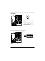
Step 2-1: Chassis Removal
Step 1 Push down the two buttons located at two sides of the chassis.
Step 2 And slide toward to remove the top cover.
After removing the top cover, you can install CPU and other essential components.
Step 1
Step 2
Push Toward
Step 2-2: CPU Installation
Please make sure the CPU type and speed that are supported by the motherboard.
Step 1 To install the CPU(s), lift up the bar that located next to the socket.
Step 2 The noticed corner should point toward the end of lever. The CPU will only it in the orientation
as shown below.
Step 3 Then, align the CPU and insert it into the socket.Then, push the lever to the original position.
Step 1
Step 2
11
GS-SR125EDL Rack mount Serv er
Step 3
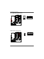
Step 2-3: Heat Sink Installation
Step 1 To install the heat sink, just simply put it on the retention module.
Step 1
Step 2-4: Memory Installation
Step 1 The DIMM slot has a notch, the DIMM memory module only fit in one direction.
Step 2 Align the memory notch to the module and push the memory into the DIMM socket.
Step 1
Step 2
Notch
12
Hardw are Installation Process
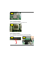
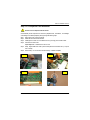
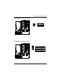
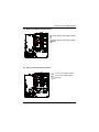
Step 2-5: PCI Expansion Card Installation
PCI Slot 2 is not compliance with this model.
GS-SR125EDL provides expansion riser slots for two peripheral cards, 100/133MHz , one full-height/
one half-length. To install the peripheral, please go through the following steps.
Step 1 Remove the screws on the riser bracket.
Step 2 Detach the riser bracket with both hands.
Step 3 Installing the PCI Riser card. To install the riser card, just simply push it into the module.
Step 4 Secure the card with screws.
Repeat Step 3 & 4 to install the rest of add-on cards.
Step 5 Finally, align the stable racks to the system module (see the arrow direction mark 1), and push
down vertically.
Step 6 Reverse Step 1 & 2 to secure the riser bracket firmly. Installation completed.
Step 2
Step 1
Step 3
Step 4
13
GS-SR125EDL Rack mount Serv er
Step 5
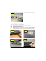
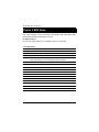
Step 2-6: Hard Disk Drive Installation
Step 1
Step 2
Step 3
Step 4
Pull the hard disk drive tray handle and remove the tray from the chassis.
Insert the hard disk drive into the tray.
Secure each hard disk drive with 4 screws.
After securing the hard disk drive with the screws, hold the hard drive handle at open position,
place the tray into chassis and push the hard disk drive tray handle to the locked position.
Step 1
Step 2
Step 4
Step 3
14
Hardw are Installation Process
Step 2-7: FAN Duct Installation
Step 1 Place the fan duct on the top of heat sinks.
Step 2 Fasten the fan duct with two screws.
Step1 & 2
Screw
Screw
Step 2-8: Reinstall Top Cover
Step 1 Gently apply force to the indentures with your thumbs and push toward the chassis (See the
arrow direction) to the lock position.
Step 1
15
GS-SR125EDL Rack mount Serv er
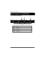
Chapter 3 Appearance of GS-SR125EDL
3-1: Front View of GS-SR125EDL
w
v
u
u
IDE HDD
v
USB Connectors
w
System LED
x
CD-ROM Disk
16
x
System Appearance
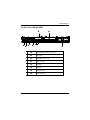
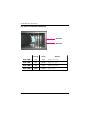
3-2: Rear View of GS-SR125EDL
w
v
u
z
{
y
x
|
u
PS/2 Keyboard & Mouse Connector
v
Low Profile
w
Full-Height / Full- Length
x
LAN 1 / 2 Ports
y
VGA Port
z
COM Port
{
USB Connectors
|
Power Connector
17
GS-SR125EDL Rack mount Serv er
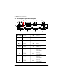
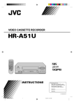
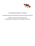
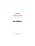
3-3: IDE Backplane Layout and Description
T
Q
E
B
S
O
P
G
L
N
K
M
H
D
I
U
X
W
V
A ,C ,D
Power
G
FAN9
F,H
FAN1
I
FAN10
K,J
FAN2
R
IDE1
M,L
FAN3
S
IDE2
O, N
FAN4
T
SMBUS1
P
FAN5
U
CON1
(SCA80-1)
Q
FAN6
V
CON2
(SCA80-2)
E
FAN7
W
CON3
(SCA80-3)
B
FAN8
X
CON4
(SCA80-4)
18
F
C
R
A
J
LED Description
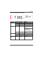
3-4: Switch and LED Indicators Description
Power LED
SYS LED
LAN LED
ID (Service LED)
Acting
Color
Status
On
Green
Pow er On
On
Blink
Amber
Green
Pow er cable is plugged in
System stands by
Off
N/A
No pow er
On
Amber
System is ready but
degraded: some CPU Fault,
DIMM Killed
Critical Pow erModules Failure,
Critical FANs Failure,
Voltage (Pow er Supply),
critical Temperature and Voltage
Normal temperature and
voltage
Off
N/A
On
Green
LAN online
Off
Blink
N/A
Green
LAN offline
LAN active
On
Blue
Identified by users
Off
N/A
N/A
19
GS-SR125EDL Rack mount Serv er
3-5: HDD LED Indicators Description
HDD LED 1
HDD LED 2
Acting
Color
HDD LED 1
Off
N/A
HDD power off
HDD LED 1
On
Green
HDD power on
HDD LED 2
Off
N/A
HDD non-active
HDD LED 2
Blink
Green
20
Status
HDD active
Connector Icon Description
3-6 : Connector Icon Description
Suggest Icon
Description
Keyboard
VGA
Mouse
LAN
Parallel Port
Serial Port
USB
21
GS-SR125EDL Rack mount Serv er
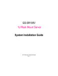
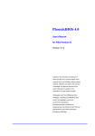
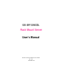
Chapter 4 Motherboard Layout & Jumper Setting
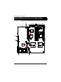
GA-8EGPDRE Motherboard Layout
Introduction
23
41 40
39
38
37 36
19
12
28 29
43
22
5
15
11
13
42
3
10
20
9 87 6
30
25
21
24
27
18
1
4
26
32
35
34 33
31
14
16
22
2
17
Connector and Jumper Setting Introduction
GA-8EGPDRE Motherboard Layout Description
1
CPU2
(Install First)
23
WOM1
2
CPU1
24
PWRDET1
3
CMIC-SL
25
SMBUS1
4
CSB6
26
SMBUS2
5
CIOBE
27
FFC1
6
DIMM1
28
PCIXSLOT2
7
DIMM2
29
PCI64_SLOT
8
DIMM3
30
Graphic Memory
9
DIMM4
31
IDE2
10
ATI Rage XL
32
IDE1
11
BIOS
33
IDE3
12
VS312AB
34
FDD1
13
BT1
35
Giga RAID
14
SYS_FAN1
36
KB_MS
15
SYS_FAN2
37
USB2
16
SYS_FAN3
38
COM1
17
CPU_FAN1
39
VGA
18
CPU_FAN2
40
GLAN1
19
POWER_FAN1
41
GLAN2
20
IPMB1
42
JP6
21
IPMB2
43
JP9
22
WOL1
44
23
GS-SR125EDL Rack mount Serv er
13) BT1 (Battery)
Li-Battery 3V
CAUTION
v Danger of explosion if battery is incorrectly
replaced.
v Replace only with the same or equivalent
type recommended by the manufacturer.
v Dispose of used batteries according to the
manufacturer’s instructions.
14 / 15 / 16) SYS_FAN1/2/3 (System Fan Connector)
SYS_FAN2
1
SYS_FAN1
SYS_FAN3
24
Pin No.
1
2
3
Definition
GND
+12v/Contr ol
Sense
Connector and Jumper Setting Introduction
17 / 18) CPU_FAN1/2 (CPU Fan Connector)
1
CPU_FAN1
CPU_FAN2
Pin No.
1
2
3
Definition
GND
+12v/Contr ol
Sense
ØPlease note, a proper installation of the CPU
cooler is essential to prevent the CPU from
running under abnormal condition or damaged
by overheating.The CPU fan connector
supports Max. current up to 600mA .
19) POWER_FAN1 (Power Fan Connector)
1
25
Pin No.
1
2
3
Definition
GND
+12v/Contr ol
Sense
GS-SR125EDL Rack mount Serv er
20 / 21) IPMB1/ IPMB 2 (IPMB Connector)
Pin No.
1
2
3
Definition
SCl_IPMB
GND
SDA_IPMB
1
22) WOL1 (Wake on LAN Connector)
1
26
Pin No.
1
2
3
Definition
+5VSB
GND
Signal
Connector and Jumper Setting Introduction
23) WOM1 (Wake on Modem Connector)
1
Pin No.
1
2
Definition
Signal
GND
24) PWRDET1 (Power Status Interface)
1
27
Pin
Definition
1
I2C_CLK
2
GND
3
I2C_Data
4
NC
GS-SR125EDL Rack mount Serv er
25 / 26) SMBUS1 / 2 (SMBUS Connectors)
1
SMBUS1
SMBUS2
27) FFC1 (IPMB I2C Bus Connector)
28
Pin
Definition
1
VCC
2
SDA
3
SCL
4
NC
5
GND
Connector and Jumper Setting Introduction
28 / 29) PCIX_SLOT2 / PCI64_SLOT(PCI Slots)
PCIX_SLOT2
PCIX_SLOT2:
Supports full-height/full-length PCI-X
PCI64_SLOT
PCI64_SLOT:
Supports low-profile half -length PCI slot
31/ 32 /33) IDE2 /IDE1 / IDE3 (IDE1 / IDE2 / IDE3Connectors)
Important Notice:
Please connect first harddisk to IDE1 and connect CDROM to IDE2.The red stripe of the ribbon cable
must be the same side with the Pin1.
IDE1
1
1
1
IDE2
IDE3
29
GS-SR125EDL Rack mount Serv er
34) FDD1 (Floppy Connector)
Please connect the floppy driv e ribbon cables to FDD. It supports 360K,720K,1.2M,1.44M and
2.88Mby tes floppy disk ty pes. The red stripe of the ribbon cable must be the same side w ith the
Pin1.
1
30
Connector and Jumper Setting Introduction
42) JP6 (PCIX_SLOT2 Bus Speed Functon)
1
1-2 close: Set the PCI-X Bus Speed at 100MHz
1
2-3 close: Set the PCI-X Bus Speed at 133MHz
(Default)
43) JP9 (PCI_SLOT1 Bus Speed Functon)
1
1
31
1-2 close: Conventional PCI Mode
2-3 close: PCI-X 66MHz(Default)
Open: Auto
GS-SR125EDL Rack mount Serv er
Chapter 5 BIOS Setup
BIOS Setup is an overview of the BIOS Setup Program. The program that allows users to modify the
basic system configuration. This type of information is stored in battery-backed CMOS RAM so that it
retains the Setup information when the power is turned off.
ENTERING SETUP
Power ON the computer and press <F2> immediately will allow you to enter Setup.
CONTROL KEYS
<á>
Move to previous item
<â>
Move to next item
<ß>
Move to the item in the left hand
<à>
Move to the item in the right hand
<Esc>
Main Menu - Quit and not save changes into CMOS Status Page Setup Menu and
Option Page Setup Menu - Exit current page and return to Main Menu
<+/PgUp> Increase the numeric value or make changes
<-/PgDn>
Decrease the numeric value or make changes
<F1>
General help, only for Status Page Setup Menu and Option Page Setup Menu
<F2>
Reserved
<F3>
Reserved
<F4>
Reserved
<F5>
Restore the previous CMOS value from CMOS, only for Option Page Setup Menu
<F6>
Reserved
<F7>
Load the Optimized Defaults
<F8>
Reserved
<F9>
Reserved
<F10>
Save all the CMOS changes, only for Main Menu
32
BIOS Setup
GETTING HELP
Main Menu
The on-line description of the highlighted setup function is displayed at the bottom of the screen.
Status Page Setup Menu / Option Page Setup Menu
Press F1 to pop up a small help window that describes the appropriate keys to use and the
possible selections for the highlighted item. To exit the Help Window press <Esc>.
l
Main
This setup page includes all the items in standard compatible BIOS.
l
Advanced
This setup page includes all the items of AMI special enhanced features.
(ex: Auto detect fan and temperature status, automatically configure hard disk parameters.)
l
Security
Change, set, or disable password. It allows you to limit access the system and setup.
l
Boot
This setup page include all the items of first boot function features.
l
Exit
There are five optionsin this selection: Exit Saving Changes, Exit Discarding Changes, Load
Optimal Defaults, Load Failsafe Defaults, and Discard Changes.
33
GS-SR125EDL Rack mount Serv er
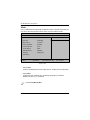
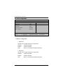
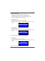
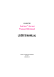
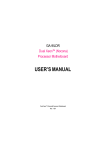
Main
Once you enter Phoenix BIOS Setup Utility, the Main Menu (Figure 1) will appear on the screen. Use
arrow keys to select among the items and press <Enter> to accept or enter the sub-menu.
Phoenix BIOS Setup Utility
Main
Adv anced
Security
Boot
Sy stem Time:
[00:13:12]
Sy stem Date:
[04/30/2003]
Lagecy Disktte A
[1.44MB 31/2]
4Primary IDE Master
[CD-ROM]
4 Primary IDE Slav e
[None]
Ex it
Item Specific Help
ø Sy stem Memory
640KB
ø Ex tended Memory
623264KB
ø Language
[Englisg (US)]
ø BIOS Version
F1: Help
Esc: Ex it
hi: Select Item
fg: Select Menu
+ -: Change Values
F5: Setup Defaults
Enter: Select4Sub-Menu F10: Sav e&Ex it
Figure 1: Main
C System Time
The time is calculated based on the 24-hour military time clock. Set the System Time (HH:MM:SS)
C System Date
Set the System Date. Note that the “Day” automatically changed after you set the date.
(Weekend: DD: MM: YY) (YY: 1099~2099)
“ø ”Indicates DISPLAY ONLY
34
BIOS Setup
C Legacy Di skette A
This category identifies the type of floppy disk drive A that has been installed in the computer.
No floppy driv e installed
8None
8360KB, 5 in.
31/2 inch AT-ty pe high-density driv e; 360K by te capacity
81.2MB, 31/2 in.
31/2 inch AT-ty pe high-density driv e; 1.2M by te capacity
8720K, 31/2 in.
31/2 inch double-sided driv e; 720K by te capacity
81.44M, 31/2 in.
31/2 inch double-sided driv e; 1.44M by te capacity .
82.88M, 3 in.
31/2 inch double-sided driv e; 2.88M by te capacity .
1/4
1/2
GNote: The 1.25MB,3
1/2
reference a 1024 by te/sector Japanese media format. The 1.25MB,31/2 diskette
requires 3-Mode floppy -disk driv e.
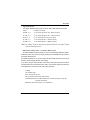
C IDE Primary Master, Slave / Secondary Master, Slave
The category identifies the types of hard disk from drive C to F that has been installed in the computer.
There are two types: auto type, and manual type. Manual type is user-definable; Auto type which will
automatically detect HDD type.
Note that the specifications of your drive must match with the drive table. The hard disk will not work
properly if you enter improper information for this category.
If y ou select User Type, related information will be asked to enter to the following items. Enter the
information directly from the keyboard and press <Enter>. Such information should be provided in the
documentation form your hard disk vendor or the system manufacturer.
8 TYPE
1-39: Predefined ty pes.
Users: Set parameters by User.
Auto: Set parameters autom atically. (Default Vaules)
CD-ROM/DVD-ROM: Use for ATAPI CD-ROM driv es or double click [Auto] to set all HDD
parameters automatically .
ATAPI Remov able: Remov able disk driv e is installed here.
35
GS-SR125EDL Rack mount Serv er
8 Multi-Sector Transfer
This field displays the information of Multi-Sector Transfer Mode.
Disabled: The data transfer from and to the device occurs one sector at a time.
Auto: The data transfer from and to the device occurs multiple sectors at a time if the device
supports it.
8 LBA Mode
This field shows if the device type in the specific IDE channel
support LBA Mode.
8 32-Bit I/O
Enable this function to maximize the IDE data transfer rate.
8 Transfer Mode
This field shows the information of Teansfer Mode.
8 Ultra DMA Mode
This filed displays the DMA mode of the device in the specific IDE
channel.
C System Memory
The POST of the BIOS will determine the amount of base (or conventional) memory
installed in the system.
The value of the base memory is typically 512 K for systems with 512 K memory
installed on the motherboard, or 640 K for systems with 640 K or more memory
installed on the motherboard.
C Exyended Memory
The BIOS determines how much extended memory is present during the POST.
This is the amount of memory located above 1 MB in the CPU’s memory
address map.
CLanguage
This field displays the language that is applied by the current system.
CBIOS version
This field displays the information of BIOS version.
36
BIOS Setup
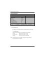
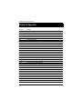
Advanced
Main
Phoenix BIOS Setup Utility
Adv anced
Security
Boot
} Adv anced Processor Option
Ex it
Item Specific Help
} PCI Configuration
} Cache Memory
} I/O Dev ice Configuration
USB Host Controller
[Disabled]
Onboard PXE Function
[Disabled]
Sy stem After AC Back
[Off]
} Console Redirection
F1: Help
Esc: Ex it
hi: Select Item
fg: Select Menu
+ -: Change Values
F5: Setup Defaults
Enter: Select4Sub-Menu F10: Sav e&Ex it
Figure 2: Adv anced
About This Section: Advanced
This section “Advanced” is divided into six sub-menus.
E Advanced Processor Option
E PCI Configuration
E Cache Memory
E I/O Device Configuration
E USB Host Controller
E Onboard PXE Function
E System After AC Back
E Console Redirection
With this section, allowing user to configure your system for basic operation. User can change the
system’s default boot-up sequence, keyboard operation, shadowing and security, etc.
37
GS-SR125EDL Rack mount Serv er
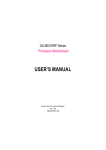
Advanced Processor Option
Phoenix BIOS Setup Utility
Adv anced
Adv anced Processor Option
Item Specific Help
Fast String Operations
[Enabled]
Compatible FPU COde
[Disabled]
Spilt Lock Operations
[Enabled]
F1: Help
Esc: Ex it
hi: Select Item
fg: Select Menu
+ -: Change Values
F5: Setup Defaults
Enter: Select4Sub-Menu F10: Sav e&Ex it
Figure 2-1: Adv anced Processor Option
CAdvanced Processor Option
4 Fast String Operations
Set the CPU fast string features.
8 Enabled
Enable CPU fast string features. (Default)
8 Disabled
Disable this function.
4 Compatible FPU Code
CPU compatible Floating Point Unit OPcode usage model.
8 Enabled
Enable CPU compatible FPU code.
8 Disabled
Disable this function. (Default)
4 Spilt Lock Operation
CPU split-lock feature setting.
8 Enabled
Enable CPU spilt-lock features.
8 Disabled
Disable this function. (Default)
38
BIOS Setup
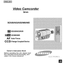
PCI Configuration
Phoenix BIOS Setup Utility
Adv anced
PCI Configuration
Item Specific Help
PCI/PNP ISA UMB Region Ex clusion
PCI/PNP ISA IRQ Resource Ex clusion
ISA graphics dev ice installed
F1: Help
Esc: Ex it
[No]
hi: Select Item
fg: Select Menu
+ -: Change Values
F5: Setup Defaults
Enter: Select4Sub-Menu F10: Sav e&Ex it
Figure 2-2: PCI Configuration
CPCI Confi guration
This section provide the addtional setup menus for users to confiure PCI devices.
4 PCI/PNP UMB Region Exclusion
Reserve specific upper memory blocks for use by legacy ISA devices.
4 PCI/PNP ISA IRQ Resource Exclusion
Reserve specific IRQs for use by legacy ISA devices.
4 ISA Graphics Device Installed
8 Yes
Enable ISA (NON-VGA) graphics devices to access palette data in PCI
VGA device.
8 No
Disable ISA (NON-VGA) graphics devices to access palette data in PCI
VGA device.
39
GS-SR125EDL Rack mount Serv er
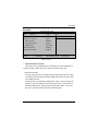
Cache Memory
Phoenix BIOS Setup Utility
Adv anced
Cache Memory
Item Specific Help
} Memory Cache
[Enabled]
} Cache Sy stem BIOS area
[Write Protect]
} Cache Vedio BIOS area
[Write Protect]
} Cache Base 0-512K
[Write Back]
} Cache Base 512K-640K
[Write Back]
} Ex tended Memory Area
[Write Back]
} Cache A000-AFFF
[Disabled]
} Cache B000-BFFF
[Disabled]
} Cache C800-CFFF
[Disabled]
} Cache CC00-CFFF
[Disabled]
} Cache D000-DFFF
[Disabled]
} Cache D400-D7FF
[Disabled]
} Cache E000-E3FF
[Disabled]
} Cache E400-F7FF
[Disabled]
F1: Help
Esc: Ex it
hi: Select Item
fg: Select Menu
+ -: Change Values
F5: Setup Defaults
Enter: Select4Sub-Menu F10: Sav e&Ex it
Figure 2-3: Cache Memory
CCache Memory
This section provide users to determines how to configure the specific block of memory.
4 Memory Cache
Set the state of the memory.
8 Enabled
Enable the memory cache.
8 Disabled
Disable the memory cache. (Default)
40
BIOS Setup
4 Cache System BIOS area
Controls caching of System BIOS area.
8 Uncached
System BIOS area is uncached.
8 Write Protect
Write/Saved settings is ingnored. (Default)
4 Cache Vedio BIOS area
Controls caching of Vedio BIOS area.
8 Uncached
Vedio BIOS area is uncached.
8 Write Protect
Write/Saved setting is ingnored. (Default)
4 Cache Base 0-512K / 512K-640K
Controls caching of 512K / 512K-640K base memory
8 Uncached
Vedio BIOS area is uncached.
8 Write Through
Writes are cached and sent to main memory at once.
8 Write Protect
Write/Saved settings is ingnored.
8 Write Back
Writes are cached, but not sent to main memory until necessary.
(Default)
4 Cache Extended Memory Area
Controls caching of system memory above one megabyte.
8 Uncached
Vedio BIOS area is uncached.
8 Write Through
Writes are cached and sent to main memory at once.
8 Write Protect
Write/Saved settings is ingnored.
8 Write Back
Writes are cached, but not sent to main memory until necessary.
(Default)
4 Cache A000-AFFF / B000-BFFF/ C8000-CFFF / CC00-CFFF / D000-DFFF /
D400-D7FF/ D800-DBFF / DC00-DFFF / E000-E3FF / E400-F7FF
8 Disabled
This block is not cached. (Default)
8 USWC Caching
Uncached Speculative Write Comboned.
41
GS-SR125EDL Rack mount Serv er
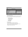
I/O Device Configuration
Phoenix BIOS Setup Utility
Adv anced
I/O Dev ice Configuration
Item Specific Help
Serial Port A
[Auto]
Serial Port B
[Auto]
Floppy Disk controller
[Enabled]
Base I/O address
[Primary ]
hi: Select Item
fg: Select Menu
F1: Help
Esc: Ex it
+ -: Change Values
F5: Setup Defaults
Enter: Select4Sub-Menu F10: Sav e&Ex it
Figure 2-4: I/O Configuration
CI/O Device Configuration
4 Serial Port A
This allows users to configure serial prot A by using this option.
8Disabled
Disable the configuration.
8Enabled
Enable the configuration.
8Auto
BIOS or O.S will select the configuration automatically.
4 Serial Port B
This allows users to configure serial prot B by using this option.
8Disabled
Disable the configuration.
8Enabled
Enable the configuration.
8Auto
BIOS or O.S will select the configuration automatically.
42
BIOS Setup
4 Floppy Disk Controller
Enable and disable the function of floppy disk controller.
8Disabled
Disable the configuration.
8Enabled
Enable the configuration.
8Auto
BIOS or O.S will select the configuration automatically.
4 Base I/O address
Set the base I/O address for the floppy disk controller by usine this option.
8Primary
Set the base I/O address to 3F0~3F7. (Default)
8Secondary
Set the base I/O address to 370~377
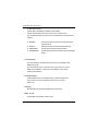
CUSB Host Controller
This option allows user to enable USB host controller.
8Enable
Enable USB host controller. (Default Value)
8Disabled
Disable this function.
COnboard PXE Function
This option allows user to enable PXE function.
8Enable
Enable PXE function.
8Disabled
Disable this function. (Default Value)
CSystem After AC Back
8On State
System power state when AC cord is re-plugged.
8Off State
Do not power on system when AC power is back. (Default Value)
8Last State
Set system to the last sate when AC power is removed. Do not power on
system when AC power is back.
43
GS-SR125EDL Rack mount Serv er
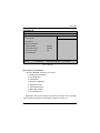
Console Redirection
Phoenix BIOS Setup Utility
Adv anced
Console Redirection
Item Specific Help
COM Port Address
[Disabled]
Baud Rate
[19.2K]
Cosole Ty pe
[PC ANSI]
Console Redirection
[Direct]
Continue C.R after POST
[Off]
# fo Vedio pages to support
[1]
hi: Select Item
fg: Select Menu
F1: Help
Esc: Ex it
+ -: Change Values
F5: Setup Defaults
Enter: Select4Sub-Menu F10: Sav e&Ex it
Figure 2-5: Console Redirection
CConsole Redirection
This option allow user to remote monitoring and controlling the BIOS by client computer.
4 COM Port Address
Set the the COM Port address for Console Redirection by usine this option.
GNote:
8COM A
Attempt to redirect console v ia COM A.
8On-board COM B
Attempt to redirect console v ia COM B.
8Disabled
Disable Console Redirction. (Default Value)
If Console Redirection is set to Enabled, user is allowed to adjust the options of
C.R Port Baud Rate and C.R after Post.
44
BIOS Setup
4 Baud Rate
Enable the specified of C. R Port Baud Rate.
8300
Enable the specific baud rate at 300.
81200
Enable the specific baud rate at 1200.
89600
Enable the specific baud rate at 9600.
819.2K
Enable the specific baud rate at 19.2K. (Default )
838.4K
Enable the specific baud rate at 38.4K.
857.6K
Enable the specific baud rate at 57.6K.
8115.2K
Enable the specific baud rate at 115.2K.
4 Console Type
Enable the specified Cosole Type.
8Options: PC-ANSI 7bit (Default), VT100, VT100 8bit, VT100F, VT-U TF8
4 Flow Control
Enable the function of flow control.
8Options: CTS/RTS (Default), None, XON, XOFF
4 Console Redirection
Identifies whether the console is connected directly to the system or a modem is functioned to
connect.
8Direct
Identifies the console is connected directly to the system. (Default)
8Via Modem
Identifies the console is connected via the modem.
45
GS-SR125EDL Rack mount Serv er
4 Continue C.R after POST
Enable Console Redirection after O.S has loaded
8On
Continue C.R after Power on Self Test.
8Off
Disable this function. (Default)
4 # of Vedio pages to support
This is the number of v edio pages to allocate for console redirection w hen v edio hardw are is not
av ailable.
46
BIOS Setup
Security
Phoenix BIOS Setup Utility
Main
Adv anced
Security
Boot
Set User Passw ord
[Enter]
Set Superv isor Passw ord
[Enter]
ø Passw ord on boot
[Disabled]
ø Fix ed disk boot sector
[Normal]
ø Diskette access
[Superv isor]
Virus check reminder
[Disabled]
Sy stem backup reminder
[Disabled]
F1: Help
Esc: Ex it
hi: Select Item
fg: Select Menu
Ex it
Item Specific Help
+ -: Change Values
F5: Setup Defaults
Enter: Select4Sub-Menu F10: Sav e&Ex it
Figure 3: Security
G
About This Section: Security
In this section, user can set either supervisor or user passwords, or both for different level of
password securities. In addition, user also can set the virus protection for boot sector.
CSet User Password
You can only enter but do not have the right to change the options of the setup menus. When
you select this function, the following message w ill appear at the center of the screen to assist
you in creating a password.
Type the password up to 6 characters in lengh and press <Enter>. The password typed now
will clear any previously entered password from the CMOS memory. You will be asked to
confirm the entered password. Type the password again and press <Enter>. You may also
press <Esc> to abort the selection and not enter a specified password.
47
GS-SR125EDL Rack mount Serv er
CSet Supervis or Password
You can install and change this options for the setup menus. Type the password up to 6
characters in lengh and press <Enter>. The password typed now will clear any prev iously
entered password from the CMOS memory. You w ill be asked to confirm the entered
password. Type the password again and press <Enter>. You may also press <Esc> to abort
the selection and not enter a specified password or press <Enter> key to disable this option.
CPassword on boot
Password entering will be required when system on boot.
8Enabled
Requries entering password when system on boot.
8Disabled
Disable this function. (Default)
CFixed disk boot sector
8Write Protect
Write protects boot sector on harddisk to protect against virus.
8Normal
Set the fixed disk boot sector at Normal state. (Default)
CVirus check reminder
8Daily
Daily displays virus check reminder message at boot.
8Ev ery Mondy
Displays virus check reminder message at boot at every Monday.
81st of ev ery month
Displays virus check reminder message at boot at the 1st of every
month .
8Disabled
Disable this function. (Default)
CSystem back up reminder
8Daily
Daily displays system backup reminder message at boot.
8Ev ery Mondy
Displays system backup reminder message at boot at every
Monday.
81st of ev ery month
Displays system backup reminder message at boot at the 1st of
every month .
8Disabled
Disable this function. (Default)
48
BIOS Setup
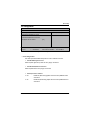
Boot
Phoenix BIOS Setup Utility
Main
Adv anced
Security
Boot
+ Remov able Dev ice
Ex it
Item Specific Help
+ Hard Driv e
CD-ROM Driv e
F1: Help
Esc: Ex it
hi: Select Item
fg: Select Menu
+ -: Change Values
F5: Setup Defaults
Enter: Select4Sub-Menu F10: Sav e&Ex it
Figure 4: Boot
G
About This Section: Boot
The “Boot” menu allows user to select among four possible types of boot devices listed
using the up and down arrow keys. By applying <+> and <Space> key, you can promote
devices and by using the <-> key, you can demote devices. Promotion or demotion of devices
alerts the priority that the system uses to search for boot device on system power on.
CBoot Device Priority
} Removable Device / Hard Drive / CD-ROM Drive
These three fields determines which type of device the system attempt to boot from after
PhoenixBIOS Post completed. Specifies the boot sequence from the available devices. If the
first device is not a bootable device, the system will seek for next available device.
49
GS-SR125EDL Rack mount Serv er
Exit
Phoenix BIOS Setup Utility
Main
Adv anced
Security
Boot
Ex it Sav ing Changes
Ex it
Item Specific Help
Ex it Discarding Changes
Load Settup Default
Discard Changes
Sav e Changes
F1: Help
Esc: Ex it
hi: Select Item
fg: Select Menu
+ -: Change Values
F5: Setup Defaults
Enter: Select4Sub-Menu F10: Sav e&Ex it
Figure 5: Ex it
G
About This Section: Security
Once you have changed all of the set values in the BIOS setup, you should save your chnages and
exit BIOS setup program. Select “Exit” from the menu bar, to display the following sub-menu.
E Exit Saving Changes
E Exit Discarding Changes
E Load Settup Default
E Discard Change
E Save Changes
CExit Saving Changes
This option allows user to exit system setup with saving the changes.
Press <Enter> on this item to ask for the following confirmation message:
Pressing ‘Y’to store all the present setting values tha user made in this time into CMOS.
Therefore, whenyou boot up y our computer next time, the BIOS will
re-configure your system according data in CMOS.
50
BIOS Setup
CExit Discarding Changes
This option allow s user to exit system setup without changing any
previous settings values in CMOS. The previous selection remain in effect.
This w ill exit the Setup Utility and restart your compuetr when selecting this option.
Press <Enter> on this item to ask for confirmation message.
CLoad Settup Default
This option allow s user to load default values for all setup items.
When you press <Enter> on this item, you will get a confirmation dialog box with a message
as below:
Setup Confirmation
Load previous configuration now?
[Yes]
[No]
CDiscard Changes
This option allow s user to load previos values from CMOS for all setup item.
When you press <Enter> on this item, you will get a confirmation dialog box with a message
as below:
Setup Confirmation
Load previous configuration now?
[Yes]
[No]
Press [Yes] to load the prev ios values from CMOS for all setup item.
CSave Changes
This option allows user to save setup daya to CMOS.
When you press <Enter> on this item, you will get a confirmation dialog box with a message
as below:
Setup Confirmation
Load previous configuration now?
[Yes]
[No]
Press [Yes] to save setup daya to CMOS.
51
GS-SR125EDL Rack mount Serv er
Chapter 6 Appendix
6-1: Acronyms
Acronyms
ACPI
APM
AGP
AMR
ACR
BBS
BIOS
CPU
CMOS
CRIMM
CNR
DMA
DMI
DIMM
DRM
DRAM
DDR
ECP
ESCD
ECC
EMC
EPP
ESD
FDD
FSB
HDD
IDE
IRQ
Meaning
Advanced Configuration and Power Interface
Advanced Power Management
Accelerated Graphics Port
Audio Modem Riser
Advanced Communications Riser
BIOS Boot Specification
Basic Input / Output System
Central Processing Unit
Complementary Metal Oxide Semiconductor
Continuity RIMM
Communication and Networking Riser
Direct Memory Access
Desktop Management Interface
Dual Inline Memory Module
Dual Retention Mechanism
Dynamic Random Access Memory
Double Data Rate
Extended Capabilities Port
Extended System Configuration Data
Error Checking and Correcting
Electromagnetic Compatibility
Enhanced Parallel Port
Electrostatic Discharge
Floppy Disk Device
Front Side Bus
Hard Disk Device
Integrated Dual Channel Enhanced
Interrupt Request
52
BIOS Setup
Acronyms
I/O
IOAPIC
ISA
LAN
LBA
LED
MHz
MIDI
MTH
MPT
NIC
OS
OEM
PAC
POST
PCI
RIMM
SCI
SECC
SRAM
SMP
SMI
USB
VID
ZCR
Meaning
Input / Output
Input Output Advanced Programmable Input Controller
Industry Standard Architecture
Local Area Network
Logical Block Addressing
Light Emitting Diode
Megahertz
Musical Instrument Digital Interface
Memory Translator Hub
Memory Protocol Translator
Network Interface Card
Operating System
Original Equipment Manufacturer
PCI A.G.P. Controller
Power-On Self Test
Peripheral Component Interconnect
Rambus in-line Memory Module
Special Circumstance Instructions
Single Edge Contact Cartridge
Static Random Access Memory
Symmetric Multi-Processing
System Management Interrupt
Universal Serial Bus
Voltage ID
Zero Channel RAID
53