1
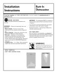
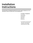
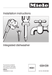
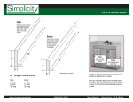
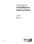
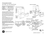
Design Guide with
Installation
Instructions
Wine Chiller, Wine Reserve
and Beverage Center
monogram.com
Safety Information
BEFORE YOU BEGIN:
WARNINGS:
Read these instructions completely and carefully.
• Use this appliance only for its intended purpose.
• Immediately repair or replace electrical service cords
that become frayed or damaged.
• Unplug the unit before cleaning or making repairs.
• Repairs should be made by a qualified service
technician.
IMPORTANT – Save these instructions
for local inspector’s use.
IMPORTANT – Observe all governing codes
and ordinances.
Note to Installer – Be sure to leave these
AVERTISSEMENT :
instructions with the Consumer.
Note to Consumer – Keep these instructions with
your Owner’s Manual for future reference.
• Il ne faut utiliser cet appareil que pour l’usage pour
lequel il a été construit.
• Il faut réparer ou remplacer immédiatement tout
cordon d’alimentation électrique effiloché ou
endommagé.
• Débrancher le bar ou le réfrigérateur a vin avant
le nettoyage ou toute intervention.
• Les réparations doivent être faites par un technicien
qualifié.
WARNING – This appliance must be properly
grounded. See page 4.
AVERTISSEMENT –
Cet appareil doit être correctement mis à la terre.
Consultez page 4.
If you received a damaged wine chiller, wine reserve
or beverage center, you should immediately contact your
dealer or builder.
For Monogram local service in your area, call
1.800.444.1845
For Monogram service in Canada, call
1.800.561.3344
For Monogram Parts and Accessories, call
1.800.626.2002.
Skill Level – Installation requires basic mechanical
skills. Proper installation is the responsibility of the
installer. Product failure due to improper installation
is not covered under the GE Appliance Warranty.
www.monogram.com
CONTENTS
Design Guide
The Installation Space ............................. 3
Product Clearances ................................... 3
Side-by-Side Installation ........................ 3
Installation Instructions
Tools, Hardware .......................................... 4
Grounding the Product ............................ 4
Staining Wood Drawer Fronts .............. 4
Installing the Custom Frame Panel ... 4
Step 1, Remove Packaging .................... 4
Step 2, Reverse Door Swing .................. 5
Step 3, Leveling ........................................... 6
Step 4, Connect Power ............................ 6
2
Step 5, Slide Product into Cutout ........ 6
Step 6, Install Nameplate ....................... 6
Step 7, Set Temperature Controls ...... 6
Custom Frame Panel Models ............... 6
ZTBSS1 Monogram
Tubular Handle Kit ..................................... 7
Template for Nameplate .. Back Cover
Design Guide
THE INSTALLATION SPACE
Locate
Outlet
10-1/2"
34-1/2"-35"
PRODUCT CLEARANCES
The stainless steel wine chiller, wine reserve and beverage
center is factory set for a 110° door swing. Models that accept
custom panels have a 95° door swing.
When installed in a corner:
• Allow 4″ min. clearance on the hinge side for the 90° door
swing and to allow racks to slide out.
• Allow 10″ minimum clearance on the hinge side for a full
110° door swing. (Models ZDWI240WII and ZDBI240WII have
a 95° door swing.)
NOTE: Custom handle clearances may vary, depending on
custom handle depth.
24"
9" Max.
1-1/2"
23-3/4" Min.
24-1/8" Framed Models
23-3/4" Stainless Steel Models
10" Minimum
to Wall
90° Door Swing
34-1/4"
to 34-3/4"
NOTE:
Handle
and handle
standoff depth
is 1-3/4″
21-5/8"
23-3/4"
23-5/8"
The cutout depth should be 24″
The cutout dimensions shown allow for a full door swing
and access to the pull-out racks when installed as a
built-in in standard 24″ deep cabinets.
• The wine chiller, wine reserve and beverage center
can be installed freestanding.
• If installing between frameless cabinets, a 1/2″ wide
filler strip or side panel may be needed on hinge side.
The filler strip will act as a spacer between the case
and adjacent cabinet door swing. The width
of the opening must include the filler panels.
NOTE: The door should protrude 1″ beyond the
surrounding cabinets. Custom framed models will
protrude 1-7/8″ beyond surrounding cabinet doors.
90°
110°*
4" Minimum
to Wall
*95° Door Swing on Custom Frame Models
• The door swing is reversible on all models. If desired, change the
door swing before installation or before installing the custom frame
panel.
Choose the location:
• These products may be closed in on the top and three sides as long
as the front is unobstructed for air circulation and proper access to
the door.
• Do not install these products where the temperature will go below
55°F (13°C) or above 90°F (32°C).
• Do not install where it will be subject to direct sunlight, heat or
moisture.
• These products are not designed to be stacked one over the other.
Black or Stainless Steel Toekick Options
• These products are shipped with a black toekick installed.
An optional stainless steel toekick is also supplied with each
product. For shipping purposes, the stainless steel toekick is
secured to the back of the unit.
ZTBSS1 Tubular Handle
ZTBSS1 Monogram stainless steel tubular handle is available for
models ZDWI240WII and ZDBI240WII.
Additional Specifications
• A 120 volt 60Hz., 15 or 20 amp power supply is
required. An individual properly grounded branch
circuit or circuit breaker is recommended. Install a
properly grounded 3-prong electrical receptacle
recessed into the back wall as shown. Electrical must
be located on rear wall as shown. NOTE: GFI (ground
fault interrupter) is not recommended.
SIDE-BY-SIDE INSTALLATIONS
Increase storage capacity by installing two Monogram
beverage centers, wine chillers or wine reserves together.
Or, for a complete refreshment center, install any two
of these units together.
• A side-by-side installation requires at least a 47-1/2″
wide opening. No trim kits required.
• Products must operate from separate, properly
grounded receptacles.
Locate
Outlet
10-1/2"
10-1/2"
14"
34-1/2"-35"
15"
9"
9"
1-1/2"
47-1/2" Min.
3
24"
Installation Instructions
TOOLS REQUIRED
STAINING WOOD DRAWER FRONTS
• #2 Phillips screwdriver
• Adjustable wrench
The drawer fronts are unfinished cherry wood. During
use, oil from hands may accumulate and stain the
wood.
• The drawer fronts may be stained and sealed to
match adjacent cabinetry. The tinted glass will make
the stained wood appear darker. A true color match
can be seen only when the door is opened.
• Apply the stain and sealer according to the
manufacturer’s instructions. To avoid unpleasant
odor, keep the door open to ventilate and allow
the stain/sealer to dry completely before using
the product.
PARTS SUPPLIED
• Monogram nameplate
• Hardware for changing door swing
• Optional stainless steel toekick with screws and
spacers
• Left and right side hinge covers
• Top screw hole cover
GROUNDING THE WINE CHILLER,
WINE RESERVE AND BEVERAGE
CENTER
INSTALLING THE CUSTOM FRAME PANEL
Go to page 6 for custom frame panel size, depending
on your cabinet size and style.
• Install a custom handle of your choice or optional
ZTBSS1 Tubular Handle onto the custom panel before
the panel is secured to the door.
• The custom panel should be installed before sliding
the product into the installation location.
IMPORTANT – Please read carefully.
FOR PERSONAL SAFETY, THIS APPLIANCE MUST BE
PROPERLY GROUNDED.
The power cord of this appliance is equipped with a
three-prong (grounding) plug which mates with a
standard three-prong (grounding) wall receptacle to
minimize the possibility of electric shock hazard from
this appliance.
STEP 1 REMOVE PACKAGING
• Remove corner blocks and foam drawer stops.
• Remove all packing material, tape and protective
plastic coverings.
• Remove stainless steel toekick taped to the back
of the unit.
Have the wall outlet and circuit checked by a qualified
electrician to make sure the outlet is properly grounded.
Where a standard 2-prong wall outlet is encountered, it
is your personal responsibility and obligation to have it
replaced with a properly grounded 3-prong wall outlet.
CAUTION: Small objects are a choke hazard
for children. Remove and discard any parts not used.
MISE EN GARDE : Les petits objets
DO NOT, UNDER ANY
CIRCUMSTANCES, CUT
OR REMOVE THE THIRD
(GROUND) PRONG
FROM THE POWER CORD.
peuvent étrangler les enfants. Il faut jeter toutes les
piéces qui ne sont pas utilisées.
DO NOT USE AN ADAPTER PLUG TO CONNECT THE
REFRIGERATOR TO A 2-PRONG OUTLET.
DO NOT USE AN EXTENSION CORD WITH THIS
APPLIANCE.
4
Installation Instructions
STEP 2 REVERSE DOOR SWING
SKIP THIS STEP IF DOOR SWING SUITS THE
INSTALLATION
Install
3 Hinge
Screws
Parts Included:
• Top left case hinge
• Bottom left case hinge
• Left and right side decorative hinge cover
• Decorative hinge screw hole cover
• Torx® driver bit
Remove
Top Hinge
Hinge
Pin and
Bracket
Tools Required:
• Phillips screwdriver
• Electric drill
Door Stop
and Cam Riser
Remove the door:
• Flatten the shipping carton to use as a pad.
• Remove the 2 screws and the toekick. Set aside the
screws and toekick for final installation.
• Use the supplied Torx® bit and electric drill to remove
the 3 screws holding the top case hinge. Lift off the
hinge. (Screws will be used to install the new hinge.)
• Lift the door off the bottom case hinge.
• Remove the bottom case hinge pin and bracket.
Remove
Hinge
Apply Monogram Nameplate:
• Install the Monogram nameplate. See instructions
and template on back cover.
Rotate the door:
The handle will be on the right side of the door; hinges
will be installed on the left side of the case.
• Remove the door stop and cam riser on the original
bottom right side of the door.
• Remove the fill plug on the top right side
of the door.
• Turn the door over and reinstall the fill plug on the
new left side.
Install Toekick
The toekick has a
cutout on the left
and right sides.
Remove
the plug on
the left side
Move Fill
and
Plug to
reinstall on
Right Side
the right
side. If you
choose to
install the
stainless steel toekick,
reinstall the plug on the right side of that toekick.
• Install original screws and spacers or screws and
spacers supplied with the stainless steel toekick.
Install screws through the spacer standoff, toekick
and into the base as shown.
Reinstall the door:
• Install the original door stop and cam riser onto the
bottom left side of the door.
• Install the new supplied bottom case hinge pin and
bracket onto bottom left side.
• Place the door onto the bottom case hinge.
• Install the supplied left-hand top case hinge with the
3 original screws.
• Select the hinge cover marked with an “L”.
• Peel backing off the tape inside the decorative hinge
cover.
Install Covers
• Press and snap the hinge
cover into place.
• Snap the screw hole cover into
place on the opposite side.
IMPORTANT:
Check to be sure screws are tight and that the door
is straight and does not sag. The door should swing
freely.
5
Installation Instructions
CUSTOM FRAME PANEL MODELS
STEP 3 LEVEL
Model ZDWI240WII and ZDBI240WII
These models require a custom panel frame surrounding
the glass. There are two options: the panel may be 29-3/4″
or 30″ high. A 30″ panel requires a notch cut into the bottom
of the panel to avoid interference with the hinges.
• Rout the back side of the panel to the dimensions shown.
• A custom handle of your choice or ZTBSS1 Tubular Handle
must be installed before the panel is mounted onto
the door.
• Use an adjustable wrench to turn the leveling legs and
raise or lower the product.
• Adjust carefully; the product should be level and plumb
with cabinetry, and should align with adjacent toekick
height.
Turn Right to Lower
Turn Left to Raise
NOTE: The 4 corners
of the routed areas
must be squared
to fit the corners
of the metal
door frame.
Option 1
Option 2
23-1/8”
23-1/8”
If you skipped Step 2:
• Select the hinge cover marked “R” or “L”, depending
on door swing.
• Peel backing off the tape inside the decorative
hinge cover. Press and snap into position.
• Snap the screw hole cover into place on the
opposite side.
2-1/4”
wide,
all sides
Rout the
back side
of the
opening
7/16”deep,
1-1/8” wide
2-1/4”
25-1/4”
25-1/4”
GLASS
29-3/4”
Rout the back
side of the
opening 7/16”
deep, 1-1/8” wide
2-1/2” at
bottom
NOTE: Right-hand models
illustrated. Cut notches
for hinge clearance on the
opposite side for left-hand
door swing.
• Connect power cord plug to a properly grounded
receptacle.
• Check to make sure power is on by opening the door
to see if interior light turns on.
30”
18-5/8”
18-5/8”
3/4” Thick Custom Panel,
Back Side
STEP 4 CONNECT POWER
GLASS
2-1/4”
1/8”
1/4”
1/4”
2-1/4”
Cut the notch
1/8” deep, 1/4”
wide and 1/4”
high
Choose Option 1 or Option 2 panel size depending on
cabinetry size or style.
NOTE: A solid panel that covers the door glass CANNOT be
installed on these models.
STEP 5 SLIDE PRODUCT INTO
THE CUTOUT
Install the custom panel:
• Open the door fully.
• Remove the gasket surrounding the inside of the door to
expose the existing screw holes for the custom panel.
• Hold the custom frame panel against the door and align
carefully, top to bottom and side to side. Mark screw hole
locations on the back side of the panel.
• Drill pilot holes in the back side of the custom panel. In
hardwood, drill 3/32″ pilot holes. In softwood, drill 5/64″ holes.
• Secure the prepared panel to the door using ten (10)
#8 x 5/8″ screws. Drive the screws through the door frame
and into the wood.
• Replace the gasket.
• Carefully, slide the unit into the opening. Be careful
not to entangle the power cord.
• Make certain that the door protrudes 1″ beyond
the surrounding cabinets (1-7/8″ for custom frame
models).
• Check again to be sure the unit is level.
STEP 6 INSTALL NAMEPLATE
• Follow instructions on the back page for installation of
the Monogram nameplate.
#8 x 5/8"
Screws
GLASS
Back
STEP 7 SET TEMPERATURE CONTROLS
• The temperature controls are preset. Refer to the
Owner’s Manual for more information. Allow 24 hours
for temperature to stabilize.
Door
Frame
Custom
Framed
Panel
6
ZTBSS1 Monogram Tubular Handle Kit
BEFORE YOU BEGIN:
TOOLS AND MATERIALS REQUIRED
Read these instructions completely and carefully.
• Gloves to protect against sharp edges
• #2 Phillips screwdriver
• Drill and 1/4″ bit and 1/2″ spade bit
• Safety glasses
• Center punch
• Pencil
IMPORTANT – Save these instructions
for local inspector’s use.
IMPORTANT – Observe all governing codes
and ordinances.
Note to Installer – Be sure to leave these
THIS KIT INCLUDES
instructions with the Consumer.
Note to Consumer – Keep these instructions
with your Owner’s Manual for future reference. This kit
provides a stainless steel tubular handle to coordinate
with other Monogram appliances.
• Tubular handle
• 2 Mounting screws
• 2 Handle standoffs
• 2 Set screws for standoffs
• 2 Nuts
• 2 Washers
• Allen Wrench
• The tubular handle must be installed onto the 3/4″ thick
portion of the custom wood panel before the panel is
secured to the door.
INSTALL THE TUBULAR HANDLE
7/8”
• Use the handle as a template to locate and mark the
exact position of the screw holes. Be careful to avoid
interference with custom panel mounting screws.
• Draw a pencil line, top to bottom and 7/8″ from the
outside edge.
• Hold the tubular handle against the appearance side,
centered on the marked line.
• Mark the screw hole locations at the center of the
handle attachment posts.
• Center punch the marked hole locations. Drill 1/4″
pilot holes from the appearance side through the
entire panel thickness.
• Use a 1/2″ spade bit to drill 1/4″ to 5/16″ deep into
the back side of the panel. Insert washer (spacer) into
the hole.
• Install screw through the handle standoff and into the
pilot hole.
• Fasten nut onto the screw until the standoff is tight
against the panel. The screw hole on the standoff
should be pointing down toward the floor.
• Place handle attachment posts inside the standoffs.
• Use the Allen wrench to install the set screws. Tighten
handle to standoffs.
30”
24-7/32”
Custom
Framed
Panel
Tubular
Handle
Handle
Standoff
Handle
Attachment
Post
Washer
Nut
Screw
7
Set
Screw
TEMPLATE FOR NAMEPLATE LOCATION
Cut on Dotted Line
Upper Left
Corner of
Glass if Hinge
is on Left
Top of Glass Door
Top of Badge
Upper Right
Corner of
Glass if Hinge
is on Right
Door Frame Side
Door Frame Side
DOOR NAMEPLATE LOCATION
To position nameplate:
• Cut template along dotted line.
• Hold or tape template behind glass
door so that it is visible from the
front side.
• Remove backing from nameplate.
• Place nameplate onto front side of
door, matching illustration on the
template.
IMPORTANT: Nameplate must
be placed on the opposite side of the
door handle.
Note: While performing installations described in this book,
safety glasses or goggles should be worn.
For Monogram® local service in your area, call
1.800.444.1845.
Note: Product improvement is a continuing endeavor at
General Electric. Therefore, materials, appearance and
specifications are subject to change without notice.
Pub. No. 31-46122-2
Part No. 197D7840P001
12-07 JR
Printed in Slovenia
GE Consumer & Industrial
Appliances
General Electric Company
Louisville, KY 40225
ge.com