1
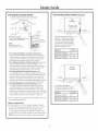
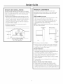
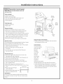
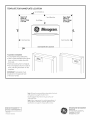
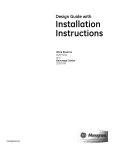
Design Guide with
installation
Instr cti
Wine Chiller, Wine Reserve
and Beverage Center
monogram.com
Safet
Information
BEFORE YOU BEGIN:
_WARNINGS:
Read these instructions completelg and carefullg.
• Use this appliance only for its intended purpose.
• Immediately repair or replace electrical service cords
that become frayed or damaged.
Unplug the unit before cleaning or making repairs.
Repairs should be made by a qualified service
technician.
IM PORTANT - Save
these
instructions
for local inspector's use.
IM PORTANT -Observe
all
codes
governing
and ordinances.
Note to Installer
- Be sure to leave these
instructions with the Consumer.
Note to Consumer - Keepthese instructions with
your Owner's Hanual for future reference.
_WARNING
-
_k AVERTISSEMENT :
• II ne faut utiliser cet appareil que pour I'usage pour
lequel il a _t_ construit.
II faut r_parer ou remplacer imm_diatement tout
cordon d'alimentation _lectrique effiloch_ ou
endommag_.
D_brancher le bar ou le r_frig@ateur a vin avant
le nettoyage ou toute intervention.
Les r_parations doivent _tre faites par un technicien
qualifi_.
This appliance must
be properly grounded. See page 5.
_AVERTISSEMENT
-
Cet appareil doit _tre correctement mis 5 la terre.
Consultez page 5.
If you received a damaged wine chiller, wine reserve
or beverage center, you should immediately contact
your dealer or builder.
For Monogram
1.800.444.1845
local service
For Monogram
1.800.561.3344
service
Skill Level -Installation
For Monogram
1.800.626.2002.
Parts and Accessories,
requires basic mechanical
skills. Proper installation is the responsibility of the
installer. Product failure due to improper installation
is not covered under the GE Appliance Warranty.
in gour area, call
in Canada, call
call
www.monogram.com
CONTENTS
Design Guide
The Instollotion Spoce..............................
3
Side-by-Side Instollotions .....................
4
Product Clearances ...................................
/4
Installation
Instructions
Tools Required ..............................................
5
Grounding the Product ...........................
5
Staining Wood Drawer Fronts .............5
Installing the Custom Frame Panel ...5
Step 1, Remove Packaging ....................5
Step 2, Reverse Door Swing ...................6
Step 5, Level ..................................................
7
Step/4, Connect Power .............................
7
Step 5, Slide Product into Cutout .........7
Step 6, Install Nameplate ........................
7
Step 7, Set Temperature Controls .......7
Custom Frame Panel Hodels ................
7
Template for Nameplate.... Back Cover
Desi n Guide
THE INSTALLATION
SPACE
THE INSTALLATION
SPACE (cont.)
.................................
.......................
Installation
Dim.A
/
]
Filler panel or cleat
to be set back even
with front of case.
34-I/2"-35"
_
Front edge of product case
CABINET
CABINET
I
Frontface
*
/
"23-3/4" Min. Standard
*'24-1/4" Min. StainlessSteelFlush
**'24-3/4" Min. FramedFlush
NOTE:
Handle and handle
standoff depth is 1-3/4"
These products will fit flush to \
adjacent cabinets when installed
with a Dim. A-width filler panel
or cleat. The filler panel should
be recessed or set back behind
the door and even with the front
edge of the product case.
Product
*For a standard installation of Custom-Framed unit: The
product must be installed so that the front face will project 2"
forward of adjacent cabinets. This position will allow a full door
swing and prevent interference with adjacent cabinetry. The
opening between cabinets must be 23-3/4" minimum.
*For a standard installation of Stainless Steel unit: The product
must be installed so that the front face will project 1-3/4"
forward of adjacent cabinets. This position will allow a full door
swing and prevent interference with adjacent cabinetrg. The
opening between cabinets must be 23-3/4" minimum.
**For a flush installation of Stainless Steel unit: Install a
1/2"-wide filler strip on the hinge side.The filler strip will act as
a spacer between the door case and adjacent cabinets and will
prevent interference with the cabinet door swing. Recessthe
filler strip 2" back from the front face of the unit, or even with
the front edge of the product case (behind the gasket).The width
of the opening must be 24-1/4" (includingthe 1/2" filler strip).
***For a flush installation of Custom-Framed unit: Install a
1"-wide filler strip on the hinge side. The filler strip will act as
a spacer between the door case and adjacent cabinets and
will prevent interference with the cabinet door swing. Recess
the filler strip 2" back from the front face of the unit, or even with
the front edge of the product case (behind the gasket).The width
of the opening must be 24-3/4" (includingthe 1" filler strip).
• The wine chiller, wine reserve and beverage center can
be installed freestanding.
Additional Specifications
• A 120 volt 60Hz.,15 or 20 amp power supplg is required.
An individual properlg grounded branch circuit or circuit
breaker is recommended. Install a properlg grounded
3-prong electrical receptacle recessed into the back wall
as shown. Electricalmust be located on rear wall as shown.
NOTE:GFI(ground fault interrupter)is not recommended.
Dim:A
ZDWI240, ZDBI240
ZDWC240,
1"
ZDWR240
1/2"
ZDBC240, ZDBR240
1/2"
Standard
Installation
CABINET
Frontedgeof productcase
Y
Dim.A
A
Front face
In a standard installation,
'\_ °°
the product will project forward
of adjacent cabinets. See Dim. A.
PrOduct
Dim:A
ZDWI240, ZDBI240
ZDWC240,
ZDWR240
ZDBC240, ZDBR240
2"
1-3/4"
1-3/4"
CABINET
Desi n Guide
SIDE-BY-SIDE
INSTALLATIONS
Increase storage capacitg by installing two Monogram
beverage centers, wine chillers or wine reserves together.
Or,for a complete refreshment center, install ang two
of these units together.
• A side-bg-side installation requires at least a 47-!/2"wide minimum opening for standard installation and
a 48-1/2"-wide minimum opening for flush installation
of stainless steel models. A 49-1/2"-wide minimum
opening is required for side-bg-side flush installation
of custom framed models.
• Products must operate from separate, properlg
grounded receptacles.
PRODUCT CLEARANCES
The stainless steel wine chiller, wine reserve and
beverage center is factorg set for a 1!0 ° door swing.
Hodels that accept custom panels have a 95° door
swing.
When instelled in a corner:
• Allow 4" min. clearance on the hinge side for the 90 °
door swing and to allow racks to slide out.
• Allow 10" minimum clearance on the hinge side for
a full 1!0 ° door swing. (Hodels ZDWI240WII and
ZDBI240WII have a 95 ° door swing.)
NOTE:Custom handle clearances mag varg, depending
on custom handle depth.
10"Minimum
to Wall
90° DoorSwing
I
10-1/2" _o,,10-1/2"I\_
,:,_4--14"-_:,-_fi 124'
34-
1-5/8"
T
i
.L
"--
[__747-1/2"
23-5/8"
\ \_
Min.Standard
_
Installatio
n\\
48-1/2"Min.Stainless
SteelFlush
49-1/2"Min.Framed
Flush
110o%
--
'\",,
,.\-:,
*95° DoorSwing on CustomFrameModels
9oY"
,jh.
4"Minimum
to Wall
• The door swing is reversible on all models. If desired,
change the door swing before installation or before
installing the custom frame panel.
Choose the location:
• These products mag be closed in on the top and
three sides as long as the front is unobstructed for air
circulation and proper access to the door.
• Do not install these products where the temperature
will go below 55°F (13°C)or above 90°F (32°C).
• Do not install where it will be subject to direct sunlight,
heat or moisture.
• These products are not designed to be stacked one
over the other.
Black or Stainless Steel Toekick Options
• These products are shipped with a black toekick
installed. An optional stainless steel toekick is also
supplied with each product. For shipping purposes, the
stainless steel toekick is secured to the back of the unit.
Installation
Instructions
TOOLS REOUIRED
STAINING WOOD DRAWER FRONTS
• #2 Phillips screwdriver
• Adjustable wrench
The drawer fronts are unfinished cherry wood. During
use, oil from hands may accumulate and stain the
wood.
The drawer fronts may be stained and sealed to
match adjacent cabinetry. The tinted glass will make
the stained wood appear darker. A true color match
can be seen only when the door is opened.
Apply the stain and sealer according to the
manufacturer's instructions. To avoid unpleasant
odor, keep the door open to ventilate and allow
the stain/sealer to dry completely before using
the product.
PARTS SUPPLIED
• Honogram nameplate
Hardware for changing door swing
Optional stainless steel toekick with screws and
spacers
Left and right side hinge covers
Top screw hole cover
GROUNDING THE WINE CHILLER,
WINE RESERVE AND BEVERAGE
CENTER
IMPORTANT - Please
read
carefully.
FOR PERSONALSAFETY,THISAPPLIANCEHUST BE
PROPERLYGROUNDED.
The power cord of this appliance is equipped with
a three-prong (grounding) plug which mates with a
standard three-prong (grounding) wall receptacle to
minimize the possibility of electric shock hazard from
this appliance.
Have the wall outlet and circuit checked by a qualified
electrician to make sure the outlet is properly grounded.
Where a standard 2-prong wall outlet is encountered, it
is your personal responsibility and obligation to have it
replaced with a properly grounded ]-prong wall outlet.
DO NOT, UNDER ANY
CIRCUMSTANCES, CUT
OR REMOVE THE THIRD
(GROUND) PRONG
FROM THE POWER CORD.
DO NOT USE AN ADAPTER PLUG TO CONNECT THE
REFRIGERATORTO A 2-PRONG OUTLET.
DO NOT USE AN EXTENSION CORD WITH THIS
APPLIANCE.
INSTALLING THE CUSTOM FRAME PANEL
Go to page rofor custom frame panel size, depending
on your cabinet size and style.
Install a custom handle of your choice onto the
custom panel before the panel is secured to the door.
The custom panel should be installed before sliding
the product into the installation location.
[STEP lj
REMOVE PACKAGING
• Remove corner blocks and foam drawer stops.
Remove all packing material, tape and protective
plastic coverings.
Remove stainless steel toekick taped to the back
of the unit.
ACAUTION:
Small objects area choke
hazard for children. Remove and discard any parts
not used.
NISE
EN GARDE
: Yespetits
objets peuvent _trangler les enfants. II fautjeter toutes
les pi_ces qui ne sont pas utilis_es.
Installation
Instructions
iSTEP 2 i REVERSE DOOR SWING
SKIPTHIS STEPIF DOOR SWING SUITSTHE
INSTALLATION
Install
3 Hinge_
Screws!
Parts Included:
• Top left case hinge
• Bottom left case hinge
• Left and right side decorative hinge cover
Decorative hinge screw hole cover
Torx®driver bit
W
I
Top
Hinge
Remove
Hinge
Pinand
Bracket
Tools Required:
• Phillips screwdriver
• Electric drill
Remove the door:
• Flatten the shipping carton to use as a pad.
• Remove the 2 screws and the toekick. Set aside
the screws and toekick for final installation.
• Use the supplied Torx®bit and electric drill to remove
the 3 screws holding the top case hinge. Lift offthe
hinge. (Screws will be used to install the new hinge.)
• Lift the door off the bottom case hinge.
• Remove the bottom case hinge pin and bracket.
Rotate the door:
The handle will be on the right side of the door; hinges
will be installed on the left side of the case.
• Remove the door stop and cam riser on the original
bottom right side of the door.
• Remove the fill plug on the top right side
of the door.
• Turn the door over and reinstall the fill plug on
the new left side.
Reinstall the door:
• Install the original door stop and cam riser onto
the bottom left side of the door.
• Install the new supplied bottom case hinge pin and
bracket onto bottom left side.
• Place the door onto the bottom case hinge.
• Install the supplied left-hand top case hinge with
the 5 original screws.
• Select the hinge cover marked with an "L".
• Peel backing off the tape inside the decorative hinge
cover.
InstallCovers
• Press and snap the hinge
_
X_
• Snap the screw hole cover into
place on the opposite side.
IMPORTANT:
ii
i
Check to be sure screws are tight and that the door
is straight and does not sag. The door should swing
freely.
Remove
Hinge
Apply Monogram Nameplate:
• Install the Monogram nameplate. See instructions
and template on back cover.
Install Toekick
The toekick has a
cutout on the left
and right sides.
Remove
the plug
on the left
side and
reinstall
MoveFill
on the right
'\,
side. If you
choose to
install the
stainless steel toekick,
reinstall the plug on the right side of that toekick.
• Install original screws and spacers or screws and
spacers supplied with the stainless steel toekick.
Install screws through the spacer standoff, toekick
and into the base as shown.
Ii1
Installation
Instructions
[STEP 3] LEVEL
CUSTOM FRAME PANEL MODELS
• Use an adjustable wrench to turn the leveling legs and
raise or lower the product.
• Adjust carefully; the product should be level and plumb
with cabinetry, and should align with adjacent toekick
height.
Model ZDWI240WIIand ZDBI240WII
Thesemodels require a custom panel frame surrounding
the glass.Thereare two options:the panel maUbe 29-3//4"
or 30"high. A 30" panel requiresa notch cut into the bottom
of the panel to avoid interferencewith the hinges.
Routthe back sideof the panel to the dimensionsshown.
A custom handle of gour choice must be installed before
the panel ismounted onto the door.
TurnRightto Lower
TurnLeftto Raise
NOTE: The 4 corners
If gou skipped Step 2:
• Select the hinge cover marked "R" or "L", depending
on door swing.
Peel backing off the tape inside the decorative
hinge cover. Press and snap into position.
Snap the screw hole cover into place on the
opposite side.
3/4" Thick Custom Panel,
....-///
2-1/4"
Back Side
[STEP 4i CONNECT POWER
illustrated, Cut notches
for
hinge
clearancemodels
on the
NOTE:
Right-hand
opposite side for left-hand
door swing,
• Connect power cord plug to a properlg grounded
receptacle.
Check to make sure power is on bg opening the door
to see if interior light turns on.
jSTEP 5jSLIDE PRODUCT
THE CUTOUT
_1/8,,
1/4,,_"
_
"
/
2-1/4"
1/8" deep, 1/4"
and
1/4"
) wide
Cut the
notch
I1__]_11_4"
_
figh
ChooseOption i or Option 2 panel sizedepending on cabinetrU
sizeor stgle.
NOTE:A solid panel that coversthe door glass CANNOTbe
installed on these models.
INTO
Install the custom panel:
• Openthe door fullg.
• Removethe gasket surroundingthe insideof the door to
exposethe existingscrew holesfor the custom panel.
• Holdthe custom frame panel against the door and align
carefullg,top to bottom and sideto side. Markscrew hole
locationson the back sideof the panel.
• Drillpilot holesin the back side of the custom panel. In
hardwood, drill 3/32" pilot holes. Insoftwood,drill 5/6/4"holes.
• Securethe prepared panel to the door usingten (10)
#8 x 5/8" screws.Drivethe screwsthrough the door frame
and into the wood.
. Carefullg, slide the unit into the opening. Be careful
notto entangle the power cord.
. Make certain that the door protrudes 1" begond
the surrounding cabinets (1-7/8" for custom frame
models).
Check again to be sure the unit is level.
[STEP 6J INSTALL NAMEPLATE
• Follow instructions on the back page for installation of
the Monogram nameplate.
• Replacethe gasket.
_
ISTEP 71SET TEMPERATURE CONTROLS
#8x 5/8"
Screws
.......Door
Frame
Back
• The temperature controls are preset. Refer to the
Owner's Manual for more information. Allow 24 hours
for temperature to stabilize.
GLASS
I_
d
7
_
Custom
Framed
Panel
TEMPLATE FOR NAMEPLATE LOCATION
CutonDottedLine
UpperLeft
Cornerof
Glass if Hinge
is on Left
A
Topof GlassDoor
Topof Badge.....................
!
Upper Right
Cornerof
Glass if Hinge
is on Right
=
=
=
=
i
i
i
DoorFrameSide
DoorFrameSide
DOORNAMEPLATELOCATION
To position nameplate:
• Cut template along dotted line.
• Hold or tape template behind glass
door so that it is visible from the
front side.
• Remove backing from nameplate.
• Place nameplate onto front side of
door, matching illustration on the
template.
IMPORTANT:Nameplate must
be placed on the opposite side
of the door handle.
Note: While performing installations described in this book,
safetg glasses or goggles should be worn.
For Monogram ® local service in your area, call
1.800.444.1845.
Note: Product improvement is u continuing endeavor at
General Electric. Therefore, materiels, appearance and
specifications ore subject to chonge without notice.
Pub. No. 31-46122-3
Part No. !97D7840PO01
09-09
JR
Printed in Slovenio
GE Consumer & Industrial
Appliances
General Electric Company
Louisville, KY/40225
GEApplionces.com