1
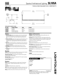
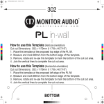
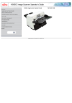
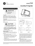
Installation Guide
GE
Lighting Solutions
Lumination LED Luminaires
TM
(Series EP14 + Lutron TVI-LMF-2A Eco)
BEFORE YOU BEGIN
Read these instructions completely and carefully.
WARNING/AVERTISSEMENT
RISK OF ELECTRIC SHOCK
• Turn power off before inspection, installation or removal.
• Properly ground electrical enclosure.
RISK OF FIRE
• Follow all NEC and local codes.
• Use only UL or IEC approved wire for input/output connections.
Minimum size 18 AWG (0.75mm2).
RISQUES DE DÉCHARGES ÉLECTRIQUES
• Coupez l’alimentation avant d’inspecter, installer ou de retirer l’unité.
• Assurez-vous de correctement mettre à la terre le boîtier d’alimentation électrique.
RISQUES D’INCENDIE
• Respectez tous les codes NEC et codes locaux.
• N’utilisez que des fils approuvés par UL pour les entrées/sorties de connexion. Taille minimum 18 AWG (0.75mm2).
Save These Instructions
Use only in the manner intended by the manufacturer. If you have any questions, contact the manufacturer.
Prepare Electrical Wiring
Electrical Requirements
• The LED driver must be supplied with 120-277 VAC, 50/60 Hz and connected to an individual properly
grounded branch circuit, protected by a 15 or 20 ampere circuit breaker. Use Min. 75°C supply conductor.
Grounding Instructions
• The grounding and bonding of the overall system shall be done in accordance with National Electric Code
(NEC) Article 600 and local codes.
imagination at work
Electrical Connections
Wiring Diagram
White
White
Orange
Black
AC line
Lutron Interface
GND (Green-Yellow)
Neutral (White)
Line (Black)
EcoSystem Link E1
EcoSystem Link E2
GND
N
Switched Hot/Out
Constant Hot/In
EcoSystem
Digital Link
Violet/White
DALI
DALI/0-10V
0-10V
Violet
Grey
0-10V
Output
–
+
Red
Blue
Red
PSU
Line
Neutral
Black
White
+
–
Black
FIXTURE
1/4-20 screws
1
Carefully unpack unit from its packaging. Install
driver enclosure to a suitable structural member
using two ¼-20 screws.
2
Risk of damage: Make sure driver enclosure is not
installed where wires can be cut by sharp edges.
Gently place enclosure cover close to the driver
enclosure. Follow wiring diagram and insert striped
wires into Lutron interface connector as described
in next step.
a) Grey
c) Green-yellow
d) White
e) Orange
b) Violet
AC line
Black
EcoSystem line
3
Connect Driver wires to Lutron interface as follows:
a) Driver 0-10V grey wire to Lutron grey connector.
b) Driver 0-10V violet wire to Lutron violet connector.
c) One green-yellow wire to Lutron green connector.
d) One Driver white wire to Lutron white connector.
e) Driver orange wire to Lutron orange connector.
4
Push out appropriate size knockout tabs and install
approved conduit connectors for both the AC and
EcoSystem lines.
E1 and E2
5
6
Connect AC line to black, white and green wires
from Lutron interface with twist-on wire caps.
Connect EcoSystem bus wires to the two purple
Lutron connectors (Link E1 and E2).
After completing connections, replace enclosure
cover and screw down M4 screws and lock washers.
Make sure screws are tight and cover is secured.
Define Distance Between Canopy Sets
Single unit installation scenario:
Canopy set
1179mm (46.4 in.)
(distance between canopy sets)
Luminaire
Multiple units in series installation scenario:
1193mm (47 in.)
1207mm (47.5 in.)
1207mm (47.5 in.)
1207mm (47.5 in.)
1st luminaire
2nd luminaire
3rd luminaire
4th luminaire
1193mm (47 in.)
5th luminaire
Distance between canopy sets for left and right luminaires = 1193mm (47 in.)
Distance between canopy sets for luminaires in the middle = 1207mm (47.5 in.)
Example: To install five units in series, the distance between canopy sets for the 1st (left) and 5th (right) luminaire is
1193mm (47 in.), and the distance between canopy sets for the 2nd, 3rd and 4th (middle) luminaires is 1207mm (47.5 in.).
Unit Installation
To driver enclosure
Junction box in ceiling
Crossbar
1
Carefully unpack unit from its packaging. Properly
inspect for defects before installing. Wear work
gloves to prevent dirt and oil from being transferred
to the luminaire.
2
Attach crossbar to junction box in ceiling with two
1/4 inch screws. Repeat on other side.
To driver enclosure
Stud
Canopy
(electrical)
Cable coupler
Strain relief
bushing
Suspension cable
Wires from luminaire
3
Connect the black (line) and white (neutral) wires
from the luminaire to the matching-colored
wires from the driver enclosure. Connect both
green wires to the grounding screw. Refer to the
EP-DKIT400UV and EP-DKIT400UD LED Driver
Installation Instructions for more information.
4
Fit canopy over stud of crossbar, then screw cable
coupler onto stud.
Squeeze tip to adjust
Tie wrap
5
To adjust height and to level a fixture, squeeze the
tip of the gripper and pull the suspension cable to
the desired height. Clip the cable with cable cutters
to finish the appearance.
6
Optional: For an improved appearance, electrical
wire can be tie-wrapped to the suspension wire.
Optional Mounting Method - Connecting Suspended Fixtures in Series
Canopy set without power cable
Canopy sets with power cable
1
For multiple units installed in series, all canopy sets will have a power cable except the last canopy.
Disconnect
suspension wire
Remove “Y” shape wires
“Y” shape
suspension wire
Bracket
2nd luminaire
1st luminaire
2
On the 1st luminaire, disconnect the right-side
suspension wire and “Y” shape suspension wire.
Then on the 2nd luminaire, disassemble the
left-side “Y” shape suspension wire (this one will
not be used).
3
Attach a bracket to each end of the “Y” shape
suspension wire using washer, spring washer
and M8 nuts. Screw torque should be between
15.3±0.8kg f.
Squeeze tip to adjust
4 Join 1st and 2nd luminaires together by fastening
the brackets on the modified “Y” shape suspension
wire from Step 9. Fasten brackets using four
M8 screws. Screw torque should be between
15.3±0.8kg f.
5
Reattach suspension wire to “Y” shape suspension
wire. To adjust height and to level a fixture, squeeze
the tip of the gripper and pull the suspension cable
to the desired height. Clip the cable with cable
cutters to finish the appearance.
Maximum Driver Remote Mounting Distance
Supply Wire Gauge
Wire Length*
18 AWG (0.82 mm )
59.0 ft. (18 m)
16 AWG (1.31 mm )
98.4 ft. (30 m)
14 AWG (2.08 mm2)
154.2 ft. (47 m)
12 AWG (3.31 mm2)
249.3 ft. (76 m)
2
2
* Includes fixture’s 6.6 ft. (2.0 m) power cord
Specifications
Input Voltage (VAC)
120 – 277V
Input Power (W)
55W
Input Frequency (Hz)
50/60 Hz
Power Factor
> 0.9
THD
< 20%
Control
0-10V & DALI
Ceilings
Cable Suspension System
Warranty
5 years
Dimensions
47.5 in. x 11.8 in. x 1.38 in. (1206 mm x 299 mm x 35 mm)
Light Fixture Weight
14.3 lbs. (6.5 kg)
Environmental Operating Temperature Range
-10°C to +25°C
Environmental Humidity (non-condensing)
20 to 80% Non-condensing, dry location rated
Environmental Storage Temperature Range
-40°C to +60°C
Conforms to the following standards:
GE Lighting Solutions • 1-888-MY-GE-LED • www.gelightingsolutions.com
1-888- 69- 43-533
GE Lighting Solutions, LLC is a subsidiary of the General Electric Company. Lumination is a trademark of GE Lighting Solutions, LLC. The GE brand and logo are trademarks of the General Electric Company.
© 2012 GE Lighting Solutions, LLC. Information provided is subject to change without notice. All values are design or typical values when measured under laboratory conditions.
IND049-121712