1
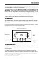
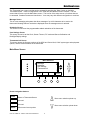
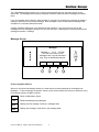
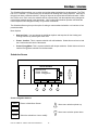
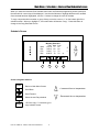
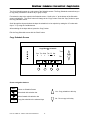
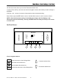
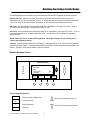
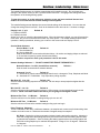
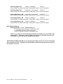
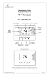
RCS
Model TZ40
Communicating Thermostat
with ZWave Communications
Installation and Operation Manual
Rev P HVAC Control Unit
DCN: 141-00885
Revision 16
Date: 1/26/06
This manual applies to these TZ40 Revisions or later
Model
Rev
Part Number
Firmware Version
TZ40 Thermostat
TS40 Wall Display Unit
P
D
001-00885
001-01060-26
3.07.4
HFR HVAC Control Unit
P
001-01430-01
3.05.2
*** IMPORTANT NOTICE ***
DO NOT USE THIS PRODUCT FOR BUILDING FREEZE PROTECTION! YOU ARE ADVISED TO
INSTALL A MECHANICAL FREEZE PROTECTION DEVICE ON YOUR SYSTEM FOR THIS PURPOSE.
Residential Control Systems Inc.
TZ40 OPERATION
The TZ40 Thermostat provides typical thermostat functions as well as the capability to send and receive
information via ZWave communications. This communications capability allows the thermostat’s setpoint,
mode and fan operation to be changed or monitored remotely.
The thermostat consists of three parts, a Wall Display Unit (WDU), a HVAC Control Unit and the ZWB
ZWave Adapter. The Wall Display Unit looks like a traditional thermostat and is the wall mounted user
interface for the TZ40. It provides display, control pushbuttons, and the temperature sensor. The WDU
connects to the Control Unit by a 4 wire cable. The Control Unit connects to the HVAC system in place of
a standard thermostat and provides thermostatic control of the system. The ZWB ZWave
communications adapter connects to the control unit RS485 port and can be located in a convenient
location up to several hundred feet from the HVAC system.
The Model TZ40 can be used with up to 3 remote temperature sensors such as the RS15.
TZ40 Wall Display Unit
The TZ40 WDU is a Model TS40 and has a backlit LCD graphical display, control buttons, LEDs and a
digital temperature sensor. The WDU can display multiple screens. In the default thermostat screen, it
shows the current temperature, setpoint, mode and manual fan mode, time, outside temperature and
other information.
Any changes in temperature, or control button operations, are transmitted to the Control Unit. Updates
are received from the Control Unit and displayed by the WDU.
Model TS40 Wall Display Unit
10:25
Indicator LEDs
Sys Off
Econ
Run
No Msg
MENU
Outside 60
75
MODE
FAN
76 H
74 C
Setpoint
Up/Down
Buttons
RUN
On-screen
dynamic labels
Heat (H) and
Cool (C)
Setpoints
Function Control Buttons
TS40 Wall Display Unit Display
The TS40 display is a graphical LCD display capable of both text and graphics. The WDU has multiple
display “screens”. The main screen is the thermostat screen shown above. This screen has a
“minimized” mode in which only the temperature is displayed. It reverts to this minimized mode after a
timeout delay period.
Other standard screens are selected by the Menu button and include: Messages, Schedules, User
Settings, and Thermostat Info. Others may be present and selectable from the menu button in special
versions of the WDU.
The TZ40’s LCD features a backlit display for low light and night visibility. It can be set to remain on
constant or to turn out after a 20-45 second delay.
DCN: 141-00885-16 1/26/06 TZ40 Thermostat Manual
2
OPERATION
Wall display Unit Control Buttons
All 6 buttons on the TS40 Wall Display Unit are “Soft Keys” meaning that they change functions when you
change screens. The function of the buttons is defined by “on-screen labels” that are dynamic and
change when you change screens. The following are definitions for the buttons for the main “Thermostat
screen” and their primary mode of operation. Other screens and their button operations are defined in
following sections.
Wall Display Unit LEDs
The TS40 has four LED’s that display various status information. The LEDs have dynamic “on-screen”
labels that can change with the screen being displayed.
Wall Display Unit “Screens”
One of the unique features of the TS40 WDU graphical display is the ability to have multiple display
screens. In addition to a main thermostat control screen, menus and other control screens for special
functions are provided. This makes an intuitive and easy to use “user interface”. It allows the many
functions of the TZ40 to be easily navigated.
The TS40’s main screen is the Thermostat Control Screen. From this screen you can access a menu
screen that will list other control screens or setup screens.
Thermostat Control Screen
This is the default main screen and the only screen needed for basic thermostat operation (temperature
setting and heat/cool mode selection). All other screens will automatically timeout and return this screen
after 120 seconds of no activity.
Minimized Thermostat Screen
The main thermostat screen will go to a “minimized” screen after a 30 second timeout period. This
presents a simple uncluttered display of the current room temperature and outside temperature (if an OT
sensor is attached). This minimized screen can be disabled if desired.
Pressing any button when the minimized screen is displayed will causes the Thermostat Control screen to
be restored and displayed.
Menu Selection Screen
Pressing the Menu button on the Thermostat Control Screen will go to the Menu Selection screen. This
screen presents a list of the other functions or setup screens that can be selected.
Messages Screen
The TS40 is capable of receiving messages from the RS485 network. Messages received are displayed
in the Messages Screen.
Schedules Screen
This screen is used to setup and select setback schedules for the thermostat.
User Settings Screen
This screen is a submenu of user settings for the initial setup of the thermostat. You can set the clock,
minimized screen timeout, Fahrenheit or Centigrade selection, sensor calibration and display settings.
Thermostat Info Screen
This is a quick reference list of the thermostat firmware versions and setup.
The following describes each Thermostat screen in detail.
DCN: 141-00885-16 1/26/06 TZ40 Thermostat Manual
3
Thermostat Control Screen
10:25
1
2
3
4
Sys Off
Economy
Run
No Msg
MENU
Outside 60
75
MODE
FAN
76 H
74 C
RUN
The thermostat control screen is the default display screen and is the screen that is normally displayed on
the Wall Display Unit. It can be set to switch to a minimized screen of only room temperature after a few
seconds of display. The User Settings menu allows selecting the screen timeout for a minimized screen.
Pressing ANY button will bring this screen back from a minimized screen.
Temperature Display
The WDU will normally display the current temperature from the internal digital temperature sensor or a
remote sensor. The sensors have an accuracy of +/- 1°F(+/- .5°C). The WDU will display temperatures
from -63°F to 191°F. NOTE: If averaging remote sensors are attached, the display will show the
average temperature of all attached averaging sensors.
Setpoint Display
The heating and cooling setpoints are displayed next to the Setpoint Up/Down buttons. In the HEAT
mode, the Up/Down buttons change the heat setpoint. In the COOL mode, they change the cooling
setpoint. When in AUTO mode, the buttons change the last call’s heating or cooling setpoint. Note that
the setpoints will “push” each other if they are adjusted to get within the minimum Heat/Cool separation
(delta T) setting. This is normally 3 degrees.
Clock Display
The current time is displayed in the upper left corner of the main screen. Set the clock from the User
Settings Menu.
Outside Temperature Display
The outside temperature is displayed in the top center of the main screen, if outside temperature
information has been sent to the thermostat or a remote outside temperature sensor is connected to the
WDU.
DCN: 141-00885-16 1/26/06 TZ40 Thermostat Manual
4
Thermostat Control Screen
Thermostat Control Screen Buttons
Thermostat Control Screen - UP and DOWN Buttons
The UP and DOWN buttons adjust the setpoint temperature.
Pressing the UP button will increment the setpoint value by one
degree and conversely, pressing the Down button will decrement
the setpoint one degree. Pressing and holding a button down
will cause the setpoint to continuously change until the button is
released.
The setpoints can be set from 40°F to 106°F ( 5°C to 37°C), unless limited in the Installer Settings.
Setpoint Push: Note that you cannot lower the cooling setpoint below the heating setpoint. The
thermostat will “push” the heating setpoint lower if try to lower the cooling below the heating setpoint. It
maintains a 3 degree separation between the heating and cooling setpoint. The same is true for raising
the heating setpoint above the cooling setpoint. Again the thermostat will “push” the cooling setpoint up to
maintain the 3 degree separation.
Thermostat Control Screen - MENU Button
The Menu button changes the screen display to the MAIN MENU screen which show what other functions
are available on the Thermostat. These are dynamic and can change with the version of the thermostat
you have, but the standard ones include:
Main Thermostat Screen
Menu Button
q Main Menu Screen
§ Messages
§ Schedules
§ User Settings
§ Thermostat Info
MENU
OFF
MODE
AUTO
FAN
RUN
Thermostat Control Screen - MODE Button
The MODE button controls the HVAC system mode. The current mode selected is displayed above the
button. Pressing the MODE button will cause the mode and display to change to the next mode. The
system mode cycles from Off to Heat to Cool to Auto and back to Off again with each press of the
MODE button. When the HVAC system type is set to Heat Pump, the mode selection will include EH for
Emergency Heat mode.
Mode Button
§ Off
§ Heat
§ Cool
§ Auto
§ EH
MENU
OFF
MODE
AUTO
FAN
RUN
Off Mode: System is off. No heating or cooling will come on. If it was on, the system will turn off.
Heat Mode: Only heating will occur.
DCN: 141-00885-16 1/26/06 TZ40 Thermostat Manual
5
Thermostat Control Screen
Mode Button Continued
Cool Mode: Only cooling will occur.
Auto Mode: Heating or cooling will come on according to the heating and cooling setpoints. The
system will automatically switch between heating and cooling when the temperature exceeds the
appropriate setpoints.
EH Mode: Only displayed when Heat Pump HVAC System type is selected. When there is a
compressor failure with the heat pump system, setting the mode to EH will allow the supplemental
heat to come on whenever there is a heat call to provide heating. It also disables the compressor
outputs to prevent further damage to the system.
Thermostat Control Screen - FAN Button
The FAN button controls the HVAC system’s MANUAL fan. The current manual fan mode is displayed
above the button. Normally this button is in the Auto mode (the system fan is automatically controlled by
HVAC system). Pressing the FAN button once will turn the manual fan operation ON. Pressing it again will
turn the manual fan OFF and return to the AUTO mode (which means OFF unless turned on by the
furnace or AC). Changes in the fan mode are sent to the Control Unit.
Fan Button
§ Auto
§ On
MENU
OFF
MODE
AUTO
FAN
RUN
Thermostat Control Screen - RUN/HOLD Button
The RUN/HOLD button controls the automatic SCHEDULE operation. In the HOLD mode, the current
temperature is maintained until changed by manual or remote network command. In the Run mode, the
schedule loaded into the thermostat is activated and setpoints will change according to the schedule and
the time and day of week. There is also an AWAY mode that you can select if you press and hold the
button for 3 seconds. In the Away mode, preset Heating and Cooling setpoints are used.
Run Button
§ Run
§ Hold
§ Away
(Press and hold button)
MENU
DCN: 141-00885-16 1/26/06 TZ40 Thermostat Manual
OFF
MODE
6
AUTO
FAN
RUN
Thermostat Control Screen
Thermostat Control Screen - LED Displays
The Thermostat Control Screen has the following LED labels and descriptions, numbered from top to
bottom, 1-4.
o
LED 1 Green: System Operation display.
o LED Off, “SYS OFF” displayed > HVAC system is OFF
o LED Off, “SYS MOT” displayed > Minimum Off Time (MOT) delay on is active
o LED On, “SYS ON” displayed > HVAC System is running
o LED On, “SYS MRT” displayed > Minimum Run Time (MRT) delay off is active
o
LED 2 Green: System Economy Mode display
o LED OFF or On, “Econ” displayed > Economy or 1st stage heating or cooling only
o LED On, “2nd Stg” displayed > Stage 2 heating or cooling is active
o LED On, “3rd Stg” displayed > Stage 3 heating is active
o LED On, “Vent” displayed > fresh air venting is active
o
LED 3 Green: Run/Hold display. Shows state of Schedule Run/Hold Mode.
o LED Off, “Run” displayed > Schedule is running
o LED On, “Hold” displayed > Schedule is off, temperature setpoint hold in effect.
o
LED 4 RED: Alert LED. Used for Messaging and other system alerts
o LED Off, “No Msg” displayed > No text messages or Alerts present
o LED On, Mail icon or Alert Text displayed > Message waiting or specific alert text
“Communications Error” Display
If the WDU is not properly wired or if communications to the Control Unit is interrupted, the LCD display
will flash “Comm Failure” at the top center of the Thermostat Control Screen (where outside temperature
is normally displayed) . Momentary display of “Communications Failure” caused by loss of data, will clear
automatically when data communication is restored. If the “Communications Failure” display stays on,
check wiring or control unit for problems.
DCN: 141-00885-16 1/26/06 TZ40 Thermostat Manual
7
Main Menu Screen
The Thermostat has a menu tree that can be accessed by pressing the “Menu” button on the Main
Thermostat screen. Various configurations of the TS40 can have different screen contents. The first
screen that will come up is the Main Menu screen. This is a list of the other menus or functions that can
be accessed. Standard screens are listed below. Yours may vary with different configuration or revisions.
Message Screen
This is a text messaging subsystem that allows message of up to 80 characters to be sent to the
thermostat. Message that are received are displayed when the message screen is selected.
Schedules Screen
This screen is used to set the programmable setback schedules of the thermostat.
User Settings Screen
This screen is used to set the Clock, Screen Timeout, F/C mode and Sensor Calibration and
Backlight/Display settings.
Thermostat Info Screen
This screen shows the firmware versions of the WDU and Control Unit, HVAC system type and equipment
options, and the network address of the thermostat.
Main Menu Screen
Menu Selection
Messages
Schedules
User Settings
Thermostat Info
Select
Done
Screen navigation buttons:
Done
Return to Thermostat Screen
Move menu selection pointer up
Not used
Not used
Select
Move menu selection pointer down
Select menu item at pointer
DCN: 141-00885-16 1/26/06 TZ40 Thermostat Manual
8
Main Menu > Messages
The TS40 Message Screen allows you to retrieve text messages sent from the serial network to the
thermostat. The message screen features navigation buttons to read new and old messages and delete
them.
Up to 16 messages can be stored in the thermostat, if more than 16 messages are received, the oldest is
erased to make room for the newest message. New messages will turn on and flash the Message LED
and Mail Icon in the main thermostat screen.
Viewing messages makes them “old” and turns off the indicators. If you view some, but not all new
messages, the new message notification LED and icon will stay on. Messages are entered as most recent
message as number 1 message.
Message Screen
Messages
Message 1 10/14 5:35 PM
The TZ40 can receive 16 text
messages, each up to 80 characters
long. They are date/timed stamped.
Done
Del
Prev
Next
Screen navigation buttons:
When you first select the Message Screen, the most recently received message will be displayed as
Message 1. If other messages are stored in memory, they can be recalled and viewed or deleted by using
the message memory navigation buttons.
Done
Del
Prev
Next
Return to Main Menu Screen
Delete the Message being displayed
Display previous message. Scroll up in message stack
Display next message. Scroll down in the message stack
DCN: 141-00885-16 1/26/06 TZ40 Thermostat Manual
9
Main Menu > Schedules
The Schedules Screen allows you to review and set the setback schedule for the thermostat. The TZ40
has a 4 x 7 schedule. Four times a day can be selected for Heating and Cooling setpoints. Each day of
the week can have a different schedule. Groups of days can be copied with the same schedule. When
the TZ40 is set to “Run” mode, the schedule will be executed daily, with the setpoints being changed as
per that days schedule stored in the thermostat. “Hold” mode stops schedule operation and holds the
current setpoints until changed manually or by network commands.
The Schedules Screen gives you the option of setting a custom setback schedule or to load one of two
preset schedules.
Menu Options
•
Heat and Cool: You can change the individual day/hour and setpoints for the Heating and
Cooling schedule by selecting this menu item.
•
Preset: Comfort: This is a preset schedule with mild setbacks. Select this menu item to load
the Comfort schedule into the thermostat.
•
Preset: EnergyMiser: This is a preset schedule with deeper setbacks. Select this menu item to
load the Energymiser schedule into the thermostat.
Schedules Screen
Select Schedule
Heat and Cool
Preset: Comfort
Preset: EnergyMiser
Select
Done
Screen navigation buttons:
Done
Return to Main Menu Screen
Move menu selection pointer up
Move menu selection pointer down
Select
Select the schedule to view or modify
DCN: 141-00885-16 1/26/06 TZ40 Thermostat Manual
10
Main Menu > Schedules > Heat and Cool Schedule Screen
When you select the Heat and Cool Schedule menu item, the Schedule programming screen opens and
the schedule for current day will be displayed. Use the scroll buttons to highlight the data to be modified.
Once the data has been highlighted, use the +/- buttons to change the value of the data.
To copy a days schedule to another or group of days, move the cursor to “c” on the bottom right of the
schedule screen. When you highlight “c”, the button below will become “Copy”. Press this button to
change to the Copy Schedule Screen.
Schedule Screen
Morn
Day
Eve
Nite
Monday Schedule
Time Heat Cool
6:00 A 72
82
9:00 A 68
84
5:00 P 74
76
10:00 P 70 78
c
Done
+
_
Next
Screen navigation buttons:
Done
Return to Main Menu Screen
+ Increment time or temperature
Scroll Back
Scroll Forward
Next
Copy
- Decrement time or temperature
Select the next Day schedule
OR if the copy “c” is selected, go to
copy schedule screen.
DCN: 141-00885-16 1/26/06 TZ40 Thermostat Manual
11
Main Menu > Schedules > Heat and Cool > Copy Schedule
The Copy Schedule screen is a sub screen of the Schedule screen. The Copy Schedule screen allows you
to copy a day’s schedule to another day or group of days.
First select the day to be copied in the Schedule screen. Scroll to the “c” at the bottom of the Schedule
screen to highlight it. The “Next” button will change to the “Copy” button. Press the “Copy” button to open
the Copy Schedule screen.
Scroll through the days and select the days the schedule is to be copied to by setting the “N” under each
day to “Y” by using the Yes/No buttons.
After selecting all the days desired, press the “Copy” button.
Exit the Copy Schedule screen with the “Back” button.
Copy Schedule Screen
Copy Monday Schedule
to
Yes
Sun Tue Wed Thu Fri Sat
N
Y
Y
Y Y N
Back
No
Copy
Screen navigation buttons:
Back
Return to Schedule Screen
Yes - Copy schedule to this day
Move back with selection bar
Move forward with selection bar
Copy
Copy the schedule to the selected days
DCN: 141-00885-16 1/26/06 TZ40 Thermostat Manual
12
No - Do not copy to this day
Main Menu > User Settings
The User Settings screen allows you to set or change various user options of the thermostat such as the
clock, Minimized Screen timeout, Fahrenheit/Celsius mode, sensor calibrations, and backlight settings.
Menu options:
•
Set Clock
Select this menu item to go to the Clock setting screen.
•
Screen Timeout
Select the Screen Timeout time in seconds. Options are 0 or 15 to 127 (default set to 30 seconds).
This is the time before any screen reverts to the Minimized Screen (temperature display only), after
you stop pushing buttons. You can disable the Minimized Screen feature by setting this time to “0”.
If this is disabled, all screens revert to the main thermostat screen after 120 seconds.
•
F/C Select
Select which temperature display mode you desire, Fahrenheit (F) or Celsius (C) with +/- buttons.
•
Sensor Calibration
Select this menu item to go to the Sensor Calibration screen.
•
Backlite/Display
Select this menu item to go the Backlite/Display settings screen. This menu allows you to set the
backlight timeout period, On and OFF backlight brightness levels and adjust the display contrast.
User Settings Screen
User Settings
Set Clock
Screen Timeout
F/C Mode
Sensor Calibration
Done
Done
30
F
_
+
Select
Return to Main Menu
Move menu selection pointer up
+
_
Increment value
Decrement value
Move menu selection pointer down
Select
Select the function to be set
DCN: 141-00885-16 1/26/06 TZ40 Thermostat Manual
13
DCN: 141-00885-16 1/26/06 TZ40 Thermostat Manual
14
Main Menu > User Settings > Set Clock
The Set Clock screen allows you to set the Thermostat internal clock.
To set the Time and Day, move the cursor with the navigation arrows until the data you want to change is
highlighted.
Using the + and – arrows to increment or decrement the data to the desired setting.
When finished, press the SET button to return to the Main Menu screen or wait for screen to timeout.
NOTE: If the clock has been reset by an extended power outage, the Clock display on the
thermostat screen will be blinking. Pressing the MENU button will take you directly to this screen
to set the clock.
Set Clock Screen
Set Clock
Time
Date
Day
+
_
12:00 PM
7/13/03
Thu
Back
Set
Screen navigation buttons:
Back
Cancel and return to User Settings Menu
+ Increment selected item
Move back with selection box
Move forward with selection box
Set
Set the time and return to User Settings Menu
DCN: 141-00885-16 1/26/06 TZ40 Thermostat Manual
15
-
Decrement selected item
Main Menu > User Settings > Sensor Calibration
The Sensor Calibration screen allows you to change the temperature calibration for the internal and any
external remote temperature sensors attached to the TZ40 WDU. You can change the temperature
calibration by +/- 7 degrees.
When the Sensor Calibration screen is selected it will show the internal and all detected remote sensors.
Each sensor found will show the current temperature (The (75) in the example screen below) and the
current number of degrees of offset being applied (1 deg in the example). “n/a” means that the remote
sensor is not attached. If the sensor’s actual temp is (74) with 0 degrees of offset and you want it to be
75, then press + to add 1 deg and it will show (75).
To change the temperature calibration, use the scroll buttons to select the internal or a remote sensor.
Once selected, use the + and – buttons to change the temperature calibration to the desired setting.
The value shown in the (xx) is the calibrated or offset temperature that you want the sensor to show.
You can update the info on this screen by pressing the right hand (blank) button.
When you close this screen, it may take a few seconds for the temperature to update to the new
temperature on the main thermostat screen.
Sensor Calibration Screen
Sensor Calibration
Internal
Remote 1
Remote 2
Remote 3
Done
(75)
n/a
n/a
n/a
1
0
0
0
+
Screen navigation buttons:
Done
+
Return to Main Menu Screen
Move menu selection pointer up
Increase the temperature by 1 deg
Decrease the temperature by 1 deg
Move menu selection pointer down
Refresh screen temperatures
DCN: 141-00885-16 1/26/06 TZ40 Thermostat Manual
16
Main Menu>User Settings>Backlite/Display
The Backlite/Display screen allows you to set the Backlite ON and OFF brightness levels and contrast.
Backlite Timeout. Sets the time from last button press that the backlite will timeout and turn off.
Adjustable from 0 or 20 to 45 seconds. If set to “0”, the backlite will never timeout and will always be ON.
If set in the range of 20 to 45 seconds, the backlite will turn OFF after the selected time expires.
ON Level. Sets the brightness of the backlite when ON. Adjustable in 10% steps, 0 to 100%. If set to
“0”, backlite will never be ON. Typically set to 100% for ON.
OFF Level. Sets the brightness of the backlite when OFF. Adjustable in 10% steps, 0 to 100%. If you do
not want the backlite to go completely dark when OFF, you can set an OFF brightness to something
greater than 0%.
NOTE: When you select an ON or OFF brightness, the display changes to that level for you to
observe the brightness setting.
Contrast. Sets the contrast level of the LCD display. Adjustable from 0 to 10. Use this control to adjust
the darkness of the display. To light and the display looks faded, too dark and dark lines will appear in the
display. Typically 5 is the correct setting. Adjust as needed.
Backlite Settings Screen
Backlite/Display
Backlite Timeout
ON Level
100%
OFF Level
Contrast
Done
0
0%
5
_
+
Select
Screen Navigation Buttons
Done
Return to User Settings menu
+
Increment value
_
Decrement value
Move menu selection pointer up
Move menu selection pointer down
Not used
DCN: 141-00885-16 1/26/06 TZ40 Thermostat Manual
17
Main Menu > Thermostat Info
The Thermostat Info screen displays the current configuration of the Thermostat Wall Display Unit and the
HVAC Control Unit. This information is useful for quick check of firmware versions and HVAC system
setup. It also shows the network address setting.
Thermostat information displayed is:
•
•
•
•
•
•
Wall Display Unit Type and Firmware version number.
Control Unit Type and Firmware version number.
System Type setting: Standard or HP HVAC system
Fan Type setting for Standard systems: No Fan w/heat (Gas systems) or Fan w/heat (Electric
systems)
OR
Changeover setting for Heat Pump systems: Changeover with cool or changeover with heat.
Network address setting: UPB Unit ID: 1 to 250
When finished viewing this screen press the Done button to return to the main Menu screen or wait for
screen to timeout.
Thermostat Info Screen
Thermostat Info
TS40R Ver:
03.07.4
HFR Ver:
03.05.2
System Type:
Standard
Fan Type:
No Fan w/HT
Network Address: 01
Done
Screen navigation buttons:
Done
Return to Main Menu screen.
DCN: 141-00885-16 1/26/06 TZ40 Thermostat Manual
18
Main Menu > Installer Settings (Hidden Screen)
The Installer Settings screen is a hidden screen designed for installer use only. Do not change any
settings in this screen unless you are a qualified service technician. Changing these settings will affect
the operation of the heating/cooling system.
To enter this screen, go to the main menu selection screen and press and hold the two inner
buttons for 3 seconds until the Installer Settings screen appears.
The Installer Settings screen displays the current internal settings of the thermostat. You can view and
change the settings from this screen. Scroll to the desired function and use the +/- buttons to change.
Display Lock: Y or N
Default: N
Y = Display LOCKED
N = Display unlocked
Allows you to lock or unlock the thermostat buttons. When the buttons are locked, you can still access the
main menu, but you will not be allowed to select any menu options. The Installer Settings hidden button
operation is always operational, allowing you to return to this screen and turn Display Lock off.
Service Mode Submenu
Service Mode: Y or N
Default: N
Y = Service Mode On.
N= Service Mode Off.
Sets the thermostat to a test mode with short delays. All runtime and staging delays are reduced
to 15 seconds to speed up system checkout and testing.
Caution: compressor short cycle protection is lost in this mode.
Network Settings Submenu *** DO NOT CHANGE FOR ZWAVE THERMOSTATS ***
Network Address: 1 to 254 (0 and 255 are reserved).
Sets the serial communications network address.
Default: 1
Autosend: Y or N
Default: N
Y = Autosend On, sends network message when there is a changes in Temp, Setpoints and Mode.
N = Autosend Off. Polled Mode. Only responds to polling requests.
Max Heat SP 10 to 109
Default: 109
Sets the maximum heating setpoint that is allowed. Will not ramp or accept setpoints higher that this
maximum.
Min Cool SP 6 to 110
Default: 6
Sets the minimum cooling setpoint that is allowed. Will not ramp or accept setpoints lower than this
minimum. NOTE: this value needs to be reset if you are going to use degree C mode.
Minimum Run Time 1- 9 Minutes
Default: 6
Sets the minimum run time before a heating/cooling cycle can turn off.
Minimum Off Time 5-9 Minutes
Default: 6
Sets the minimum off time before another heating/cooling cycle can begin.
Delta T Settings Submenu:
This is a submenu of the delta, or difference between, the setpoint and current temp for determining when
a heat or cool call comes on. Deltas are the number of degrees away from setpoint.
H/C Delta – Setting the minimum separation between heating and cooling setpoints. Attempts to
lower the cooling below the heating setpoint by this amount will PUSH the heating setpoint down
to maintain this separation. Same for setting the heating setpoint above the cooling setpoint will
PUSH the cooling setpoint up to maintain this separation. Range is 3 to 15 degrees. Default set
to 4 degrees.
DCN: 141-00885-16 1/26/06 TZ40 Thermostat Manual
19
Heat Delta Stage 1 ON
Range 1 to 8 degrees
Default: 1
Sets the delta from setpoint that stage 1 heating starts. Stage 1 turns off at setpoint.
Heat Delta Stage 2 ON
Range from 1 to 8 degrees
Default: 3
Sets the delta from setpoint that stage 2 heating starts. Stage 2 turns off at setpoint.
Heating Delta Stage 3 ON
Range from 1 to 8 degrees
Default: 5
Sets the delta from setpoint that stage 3 heating starts. Stage 3 turns off at setpoint.
Cooling Delta Stage 1 ON
Range 1 to 8 degrees
Default: 1
Sets the delta from setpoint that stage 1 cooling starts. Stage 1 turns off at setpoint.
Cooling Delta Stage 2 ON
Range 1 to 8 degrees
Default: 3
Sets the delta from setpoint that stage 2 cooling starts. Stage 2 turns off at setpoint.
WDU Settings Submenu
Messaging Enable: Y or N
Default setting: N
N = “Messages” does not appear in main menu screen
Y = “Messages” appears in main menu screen.
Enables or disables the network messaging function.
NOTE: If you intend to use the messaging capability of the TS40, you must enable it here
by setting to Y. “Messages” will then appear as a menu item in the main menu and you
will be able to receive and browse through the messages.
INSTALLER SETTINGS CAUTION! Do not change these settings unless you are sure of the effect
these changes will make. Changing the network address will make the thermostat not respond if
the address is incorrect.
DCN: 141-00885-16 1/26/06 TZ40 Thermostat Manual
20
Installer Settings Screen
Installer Settings
Display Lock
Service Mode
Network Addr
Autosend
+
Done
N
1
N
Select
Screen navigation buttons:
Done
+
Return to Main Menu screen
Move menu selection pointer up
Increase by 1 or change from Y to N
Decrease by 1 or change from Y to N
Select
Select menu item to go to a submenu
DCN: 141-00885-16 1/26/06 TZ40 Thermostat Manual
21
Move menu selection pointer down
TZ40 Installation
STOP
Before proceeding with removing an existing thermostat and installing the TZ40,
Read the following important steps.
1.
2.
3.
4.
Record existing wiring information on the enclosed wiring form.
Perform the TZ40 bench test
Check WDU wiring BEFORE applying power to control unit.
Be sure to install a freeze protection device as required.
Installation Overview
Standard thermostat wiring vs TZ40 in retrofit applications.
Heating &
Cooling
System
OLD
Thermostat
4, 5 or 6 wires
18Ga thermostat wiring
Insert Control Unit into
the thermostat wiring
Replace
Thermostat with
Wall Display Unit
Heating &
Cooling
System
NEW
4 Wires
TZ40
Wall Display
Unit
TZ40
Control
Unit
4,5 or 6 wires
as original
installation
Freeze Protection.
In cold climates that require the heating system to be used for building freeze protection, a mechanical
backup freeze protection device MUST be installed on the heating system. This can be a simple
mechanical heating thermostat or a preset thermoswitch installed in the heated area.
40-45°
Mechanical
Thermostat or
Thermoswitch
R
Red Wire
W
White Wire
24VAC R
Heat W
Heating
System
Thermostat connections
Wire across Heater R/W terminals.
DCN: 141-00885-16 1/26/06 TZ40 Thermostat Manual
22
TZ40 Wall Display Unit Installation
WDU Location. Choose a location that best represents the temperature of the area to be controlled.
Avoid locations that are subject to drafts, from doors and windows, or areas with direct sunlight exposure.
WDU Mounting
Route the wires to the WDU through the access hole in the back of the case. Mount the WDU to the wall
with the screws and anchors provided. Be sure to plug any large access hole in the wall with sealer or
insulation to prevent wall drafts from affecting WDU operation.
WDU Prewiring
For new construction, the recommended wiring to the WDU from the Control Unit should be a two twisted
pair cable, 22 Ga minimum. Use of Category 5 wiring is preferred, but not required. In retrofit
applications the existing 18Ga thermostat wiring (a least 4 wires) is adequate and usually will work without
problems. However, such non-twisted wiring can be subject to interference due to adjacent in-wall high
voltage wiring.
Wiring the WDU to the Control Unit
Wiring the WDU is simply connecting the four wire cable from the Control Unit to the WDU terminal block.
Two wires are for data and two are for power. WDU power is 12VDC and provided by the Control Unit.
CAUTION:
DO NOT MISWIRE THE POWER AND DATA LINES…DAMAGE WILL RESULT!!!
CHECK YOUR WIRING BEFORE APPLYING POWER…
Hook TOP here and rotate into
base. Be sure pins engage in
connector correctly.
TZ40 WDU
BASE
BASE
WIRING
ACCESS
HOLE
TO CLOSE
J2
CLOSE
J1
G
+5
C
D
+
C
D
TO OPEN
PULL FROM LOWER CORNERS
For Remote Sensor
TZ40 WDU WIRING DIAGRAM
OPENING AND CLOSING THE WDU CASE
Remote Sensor Connection
Model TS40 WDU has an remote sensor connector, J2, on the WDU base for connection of an external
remote temperature sensor. Follow the wiring diagram with the remote sensor to connect to the WDU.
DCN: 141-00885-16 1/26/06 TZ40 Thermostat Manual
23
1 GND
2 +12V
3 CLOCK
4 DATA
TZ40 Control Unit Installation
Location and Mounting
Install the TZ40 Control Unit in a protected, convenient, INDOOR location near the HVAC system or in a
service accessible area such as an equipment closet or garage.
Mount the Control Unit in a vertical position on a wall or sturdy structural member. The unit may be
mounted on the HVAC system but care should be taken to avoid the hot burner section or high vibration
areas.
Control unit wiring
The TZ40 HVAC Control Unit is connected to the HVAC system and to the Wall Display Unit as well as
the serial communications and power connections.
Control Unit to WDU wiring
Connect the WDU to the Control Unit with existing thermostat wiring in retrofit installations. For new
installs, 22/24 GA twisted pair, typically Cat3 or Cat 5 wiring is preferred.
Control Unit
WDU
TS40
GND
J1
GND
G
+12V
+12VDC +V
CLK
CLOCK
C
DATA
D
DATA
CAUTION!
Be careful to not miswire the Wall Display Unit to Control Unit connections as damage may result.
Control Unit to HVAC System wiring
Electrically, the Control Unit looks like a standard thermostat to your HVAC system. All connections to
the HVAC system are made at the normal thermostat connections on the HVAC unit.
You are advised to refer to your HVAC system’s documentation for specific information on its thermostat
connections and setup requirements. You must know the following:
1. HVAC system type: Gas, Electric, Heat Pump, Radiant, Hydronic
2. Fan requirement: No fan with Heat or Fan with Heat
3. For Heat Pump systems: Changeover with cool or with heat. (O or B connection)
Note on retrofit wiring. You may note (and be sure to note on the wiring form) that you have additional
wires when you disconnect your old thermostat. Usually these wires are for auxiliary functions such as
filter or trouble indicators. For Heat Pump systems there may be emergency heat (EH) wiring or both O
and B changeover connections. These wires are not used in the TZ40 installation and, in most cases,
these extra wires are not required for normal HVAC system operation.
Refer to the following HVAC wiring diagrams for your type of HVAC system, Standard Or Heat Pump.
DCN: 141-00885-16 1/26/06 TZ40 Thermostat Manual
24
HVAC System Wiring
Diagram 1 - Standard Gas or Electric System Wiring
TZ40 Control Unit
FUSE
IMPORTANT! For typical central heating/cooling systems,
leave jumper JP1 installed. If you have separate Heating and
Cooling system transformers, CUT JUMPER JP1. Wire RC
to the Cooling system transformer and RH to the Heating
system transformer.
SW1
STD 1
S2 2
HP
Standard HVAC System
OFF ON
JP1
Note: Set SW1-S1 to STD
S2 to OFF
THERMOSTAT CONNECTION
RC&RH
C 24VAC Common
24V COM
24V RH
Red (or RH for split systems)
24V RC
Red (or RC for split systems)
R 24VAC Return
Wire R to either RH or RC for common
transformer HVAC systems
W1 Heat 1
White
W2 Heat 2
Orange
G Fan
Green
G Fan
Y1 Comp 1
Yellow
Y1 Comp Stage 1
Y2 Comp 2
Black
Y2 Comp Stage 2
W1 Heat Stage 1
W2 Heat Stage 2
J4
HVAC SYSTEM
HFRU REV P
Typical thermostat wiring color codes
Standard HVAC System Setup Notes:
Single Stage Systems use W1 for heating stage 1, and Y1 for cooling stage 1.
Two Stage Heating systems use W1 for stage 1 and W2 for stage 2 heating.
Two Stage Cooling systems use Y1 for stage 1 and Y2 for stage 2 cooling.
HVAC System 24VAC Transformer
If you have an integrated heating and cooling system with a single transformer, do NOT cut jumper JP1.
Wire the 24V Return (red) wire to either RH or RC. This is typical of most central systems.
If you have separate heating and cooling systems with separate transformers, cut jumper JP1. Wire the
heating 24V R (red) wire to the control unit’s RH terminal and run the cooling systems 24V R (red) wire to
control unit’s RC terminal. Also wire the cooling systems 24VAC Com to the control units 24VAC Com
terminal.
Dipswitch SW1 Setup for Standard HVAC Systems
1. Set SW1-1 (position 1) to the STD position. (Off - to the left) (default setting)
2. Set SW1-2 (position 2) to the correct setting for your HVAC system.
a. Gas furnaces do not require fan outputs for heating calls. Set SW1-2 to the Off - to the left.
(default)
b. Electric furnaces do require fan outputs for heating calls. Set SW1-2 to the On - to the right.
DCN: 141-00885-16 1/26/06 TZ40 Thermostat Manual
25
HVAC System Wiring
Diagram 2 - Heat Pump System Wiring
TZ40 Control Unit
FUSE
SW1
STD 1
S2 2
IMPORTANT! Do not cut JP1 for Heat Pump Systems.
RC and RH are common for Heat Pumps.
HP
OFF ON
Heat Pump HVAC System
JP1
Note: Set SW1-S1 to HP
And S2 to correct Changeover valve
setting
RC&RH
THERMOSTAT CONNECTION
24C COM
Blue
24V RH
Red
C 24VAC Common
R 24VAC Return
24V RC
Wire R to either RH or RC
W1 Heat 1
White
W2/O CO
Orange
G Fan
Green
Y1 Comp 1
Yellow
Y2 Comp 2
Black
W1 Heat Strips (Heat Stage 3 )
O Changeover Valve
G Fan
Y1 Comp Stage 1
Y2 Comp Stage 2
J4
HVAC SYSTEM
HFRU REV P
Typical thermostat wiring color codes
Heat Pump HVAC System Setup Notes:
Single Stage Compressor Systems use Y1 for stage 1 heating/cooling, and W1 for stage 2 heating (heat
strips).
Two Stage Compressor Systems use Y1 for stage 1, Y2 for stage 2 heating/cooling, and W1 for stage 3
heating (heat strips).
NOTE: You must configure the Changeover valve setting to work correctly with your HVAC
system. Set Dipswitch SW1 as below for correct changeover operation. Changeover with cool is
typical for most systems. Check your system information to be sure. If you get cooling when you
expect heating, change SW1-S2 to the other position.
Dipswitch SW1 Setup for Heat Pump HVAC Systems.
1. Set SW1-1 (position 1) to the Heat Pump position. (On - to the right)
2. Set SW1-2 (position 2) to the correct changeover (reversing valve) setting for your Heat Pump
system.
a. For systems with changeover with cooling, Set SW1-2 to Off - to the left (default setting)
b. For systems with changeover with heating, Set SW1-2 to On - to the right
DCN: 141-00885-16 1/26/06 TZ40 Thermostat Manual
26
TZ40 Power Connection
The TZ40 Control Unit requires 24VAC power from the HVAC system it is controlling. Connect the
24VAC Common (Blue wire/terminal) and 24VAC R (Red wire/terminal) from the HVAC system to the
control unit’s HVAC System terminal block J4’s 24VCom and 24V RH or 24V RC terminals (the RH and
RC terminals are default jumpered together…see below)
Common or Split Transformer Systems
Most HVAC systems have a common heating and cooling transformer. Connector JP1 is jumpered to
common the RH and RC inputs together for this configuration. If you have a system with separate heating
and cooling transformers, you will need to split the RH and RC jumper by cutting the JP1 jumper.
When wiring split systems, wire the heating systems 24VAC R (red wire) to the Control units RH terminal,
and wire the cooling systems 24VAC R to the control units RC terminal. Also wire the cooling systems
24VAC Com to the control units 24VAC Com terminals.
DCN: 141-00885-16 1/26/06 TZ40 Thermostat Manual
27
TZ40 ZWave Adapter
The TZ40 comes with an external ZWave adapter (ZWB) that connects to the TZ40 RS485 port. The
RS485 port is dedicated to the ZWave adapter and cannot be used for other communications.
NOTE: DO NOT CHANGE THE DEFAULT RS485 ADDRESS OF THE THERMOSTAT (SET TO 1).
The TZ40 supports the standard ZWave protocol for thermostats.
Connect the adapter as shown and proceed with enrolling the device into your ZWave network.
ZWB ZWave Thermostat Adapter Wiring
1. Place the ZWB in a convenient location that gets good ZWave reception. You must have access
to the ZWB module to set the ZWave network address.
2. Connect the ZWB to the TZ40 HVAC control unit with 22-24Ga wiring. (Category 3-5 wiring
acceptable). Wiring can be up to 1000ft.
3. Connect the D+, D- and Gnd terminals on the ZWB module to the RS485 connection on the TZ40
control unit.
4. Connect the 12V terminal on the ZWB to the 12V terminal on the WDU terminal on the TZ40
control unit.
5. Power up TZ40 HVAC control unit and observe that the ZWB Power LED is on.
6. Enroll the ZWave adapter in to the ZWave network using a ZWave network remote or other
control system interface.
7. Confirm ZWave message traffic with the Network LED.
TZ40
Control Unit
WDU
GND
J1
12V
C
D
ZWBT-485
ZWave Thermostat
Adapter
RS485
GND
Network
Data LED
Power LED
D+
D-
RX/DProgram
button
TX/D+
Gnd
12V
DCN: 141-00885-16 1/26/06 TZ40 Thermostat Manual
28
J2
System Checkout
It is strongly recommended that you hook-up and run a simple bench test before installing the TZ40. Not
only will this save you time in system checkout but will also familiarize you with the thermostat’s
operation.
THERMOSTAT BENCH TEST
1. Connect the Wall Display Unit to the Control Unit with a short (12-24 inch) 4 wire cable.
2. Before power up, set the Control Unit dipswitch, SW1, to ALL OFF
3. Connect power to the Control Unit.
4. Verify Control Unit Status LED is blinking.
5. Verify the WDU display comes on and shows the current temperature.
a. If no display and backlights are not on, check wiring and power at the Control Unit.
b. If a “CF” display is shown on the WDU, double check your wiring to the Control Unit.
d. Do not proceed until the current temperature is displayed on the WDU.
6. With the current temperature displayed on the WDU, we have verified communication between it and
the Control Unit is OK. Any communication problems will result in a “CF” (Communications Failure)
display on the WDU and must be fixed before proceeding. If all is OK with the WDU proceed to the next
step.
7. Press the Fan button on the WDU. The Control Unit’s Fan LED and relay should turn on.
8. Press the Fan button again. The Fan LED and relay should turn off.
9. Press the Mode button until the WDU is showing “H” for Heat Mode.
10. Press the Setpoint Up button until the setpoint is above the current temperature. The Heat LED and
relay should come on. (If they don’t, make sure the Status LED is not flashing twice indicating minimum
off delay…wait until LED stops flashing twice before proceeding).
11. Press the Mode button until the WDU is showing “O” for OFF. The Heat LED and relay will turn OFF.
12. Wait 6 minutes for the minimum off delay to expire. The Status LED will stop flashing twice.
13. Press the Mode button until the WDU is showing “C” for Cool Mode.
14. Press the Setpoint Down button until the setpoint is below the current temperature.
15. The Compressor and Fan LEDs and relays should turn on.
16. Press the mode button until the WDU is showing “O” for OFF Mode.
17. All LEDs and relays should turn off.
18. When you have successfully completed all these tests, you have verified that the TZ40 is working
correctly.
DCN: 141-00885-16 1/26/06 TZ40 Thermostat Manual
29
HVAC System Testing
If you have difficulty with the HVAC system operation, you can perform the following test to verify the
HVAC system is operational.
Thermostats, like the TZ40, are just switches to the HVAC system as shown in the diagram below.
This is a simplified example of a thermostat and a standard HVAC wiring diagram. The HVAC system
operation can be tested by duplicating the thermostat switch operation by shorting across the thermostat
terminals on the HVAC system.
HVAC SYSTEM
STANDARD GAS/AC
TYPICAL THERMOSTAT
C 24VAC COMMON
24VAC
R 24VAC HOT
FAN
G FAN
HEAT
W HEAT
COMP
Y COMP
Thermostat
Connection
FAN
RELAY
GAS
VALVE
COMP
RELAY
Note: The HVAC system and thermostat connection voltage is 24VAC. This is a safe voltage to
work with but be careful to avoid shorting the 24VAC common (C) and 24VAC return (R) terminals.
This may blow a fuse in the HVAC system.
Standard HVAC System Quick Test
You can perform a quick test of the HVAC system by shorting across the appropriate thermostat terminals
on the HVAC thermostat connector. Use a short 6 inch wire to connect across the following terminals.
Function Test
Fan
Heating
Cooling
HVAC Terminals
R to G
R to W
R to Y and G
Result
Fan should come on
Heat cycle should start for heating
Compressor and Fan should start for cooling
Heat Pump System Quick Test
Similarly, you can test Heat Pump operation by shorting across the following terminals. Heat pump
operation is determined by compressor calls in conjunction with changeover (O) outputs. You must know
what your system CO type is (CO with Cool (typical) or CO with Heat). You should have configured the
TZ40 control unit for correct CO type, refer to this setting. Heat Pump systems have an additional O
terminal.
Function Test
Fan
Heating
HVAC Terminals
R to G
R to Y and G
Cooling
R to Y and G and O
Result
Fan should come on
Compressor and Fan should start and Heating
occurs.
Compressor and Fan should start.
CO valve operates and Cooling occurs.
Note: if you have the CO selection incorrect you will get cooling when you expect heating and vice versa.
Change the dipswitch SW1-2 changeover setting to correct this problem.
DCN: 141-00885-16 1/26/06 TZ40 Thermostat Manual
30
RCS
TZ40 Wiring Diagram
TZ40 CONTROL UNIT
SW1
TS40
WALL DISPLAY UNIT
WDU
GND
G
+12VDC +V
GND
C
DATA
D
D
24V COM
Blue
24V RH
HEAT1
HEAT2
CO
RS485
GND
J2
D+
FAN
24V RC
W1
W2 / O*
COMP1
DCOMP2
Program
HVAC SYSTEM
JP1
STATUS
C
RH=RC
Cut Jumper
to split
J1
12V
CLOCK
ZWBT-485
ZWave Thermostat
Adapter
Fuse
Mini ATO
2 Amp
STD 1
HP
S2 2
OFF ON
RX/D TX/D +
GND
+12V
THERMOSTAT CONNECTOR
C - 24VAC Common
Red
R - 24VAC Return
White
W1 – Heat Stage 1
Orange
W2/O* – Heat Stage2
G
Green
Y1
Yellow
Y1 – Comp Stage 1
Y2
Black
Y2 – Comp Stage 2
J4
HVAC SYSTEM
G – Fan
* for HP HVAC Systems
O=Changeover Valve
HFRU REV P
Typical Thermostat wiring colors.
HVAC System Transformer:
Most central HVAC systems have a common heating and cooling transformer. This is the factory default
setting for Jumper JP1. In some cases, you may have separate heating and cooling systems, each with their
own transformer. In that case, cut Jumper JP1 and wire the heating transformer red wire to the RH terminal
and the cooling system transformer red wire to the RC terminal. Wire the cooling system’s 24VAC Com to
the control unit’s 24VAC Com terminal.
Dipswitch SW1 Settings:
(White is switch position)
SW1-S1, STANDARD OR HEAT PUMP SYSTEM SELECTION
HVAC Systems can be either Standard Gas/Electric systems or Heat Pump systems.
Set S1 to STD SYS (OFF) for Gas/Electric systems (default setting).
Set S1 to ON for Heat Pump systems
SW1-S2 Fan or Change Over Valve Selection
If S1 is set to Off for Standard HVAC systems, then S2 selects the HVAC fan type.
Set S2 to OFF for gas systems that do not require Fan w/heat calls.(default setting)
Set S2 to ON for electric systems.
If S1 is set to On for HP HVAC systems, then S2 selects the changeover or reversing valve type.
Set S2 to OFF for changeover with cooling (default setting).
Set S2 to ON for changeover with heating
DCN: 141-00885-16 1/26/06 TZ40 Thermostat Manual
31