1
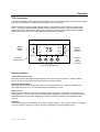
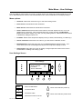
RCS
Model TZ43
ZWave Thermostat
INSTALLATION
AND
OPERATION MANUAL
DCN: 141-01652-03
9/22/08
*** IMPORTANT NOTICE ***
DO NOT USE THIS PRODUCT FOR BUILDING FREEZE PROTECTION! YOU ARE ADVISED TO
INSTALL A MECHANICAL FREEZE PROTECTION DEVICE ON YOUR SYSTEM FOR THIS PURPOSE.
Model: TZ43
ZWave Thermostat
This manual applies to the following product revisions or later revisions up to the next manual revision
release:
Product
Part No:
Firmware
ZWave Thermostat
001-01652-01
Document Revision History
Revision
01
02
03
Date
7/30/08
8/22/08
9/22/08
Changes
Original release
Updated Zwave Install description
Updated Zwave command class information
Product Specifications
Product Model:
Product:
Thermostat
Size:
Display:
Backlight:
Contrast:
Buttons:
LEDs:
Temp sensors:
Power:
TZ43
Thermostat for Heating and Cooling HVAC System control.
ZWave RF communications enabled
5.7” wide x 4.0” height x 1.2” depth
Graphical LCD, 2.75” x 1.5”, 64x128 pixel
Yes, Blue/white, Controllable, on, off, timeout
adjustable on screen
6
4 (3 green, 1 red)
2 remote
24VAC from HVAC System
HVAC System Type Compatible:
Multistage System Compatible:
Standard HVAC Systems:
Heat Pump Systems:
Heat Pump change over valve:
2 stage heating, 2 stage cooling
3 stage heating (2 compressor, 1 aux), 2 stage cooling
Selectable change over with cool or with heat
Outside temp sensor:
Communications:
2 wire, 10K NTC thermistor type
ZWave RF
DCN 141-01128-03 9/22/08
Standard (gas/electric) or Heat Pump
2
Table of Contents
Overview ...................................................................................................................................................... 4
Z-wave® Programming and Operation ..................................................................................................... 5
Operation ..................................................................................................................................................... 6
Thermostat Control Screen........................................................................................................................ 7
Temperature Display ................................................................................................................................. 7
Setpoint Display......................................................................................................................................... 7
Clock Display ............................................................................................................................................. 7
Outside Temperature Display (optional) .................................................................................................... 7
Thermostat Control Screen Buttons .......................................................................................................... 8
LED Displays ........................................................................................................................................... 10
Main Menu.................................................................................................................................................. 11
Schedules Screen.................................................................................................................................... 12
User Settings Screen............................................................................................................................... 15
Thermostat Info Screen ........................................................................................................................... 21
Main Menu > Installer Settings (Hidden Screen)................................................................................. 22
Installer Settings Summary...................................................................................................................... 25
HVAC System Connection........................................................................................................................ 27
HVAC System Compatibility .................................................................................................................... 27
Remote Communications ........................................................................................................................ 27
Outside Temperature Operation.............................................................................................................. 27
HVAC System Operation and Setup ........................................................................................................ 28
Standard HVAC System Types ............................................................................................................... 28
Heat Pump HVAC System Types ............................................................................................................ 28
Remote Temperature Sensors ................................................................................................................ 30
Power....................................................................................................................................................... 31
Standard Gas/Electric HVAC System Wiring .......................................................................................... 32
Heat Pump HVAC System Wiring ........................................................................................................... 33
HVAC SYSTEM QUICK TEST ................................................................................................................... 34
ZWave Command Class Information....................................................................................................... 36
TZ43 Variable Table ................................................................................................................................ 36
DCN 141-01128-03 9/22/08
3
Overview
TZ43 Thermostat
The TZ43 thermostat provides for typical thermostat control of a central heating and cooling HVAC system
plus has the added feature of ZWave communications for remote control.
The thermostat has a large, backlit graphical display, control buttons, status LEDs and a temperature
sensor. The thermostat can display multiple screens for different functions of the thermostat. In the
default thermostat control screen, shown below, it displays the current temperature, setpoint, system
mode, manual fan mode, time, outside temperature and other information.
10:25 AM
Status
Indicator
LEDs
Sys Off
Econ
Run
No Msg
MENU
Outside 60
75
MODE
FAN
76 H
74 C
Setpoint
Up/Down
Buttons
RUN
On-screen
dynamic labels
Heat (H)
And
Cool (C)
Setpoints
Function Control Buttons
Display operation
Thermostat control screen
Normally the thermostat displays the thermostat control screen as shown above. Using the “Menu”
button, you can access other screens and functions of the thermostat.
Minimized Display Mode
Optionally, you can set the thermostat to show only the temperature in a “minimized” display mode.
This mode can be set on or off in the thermostat “Users Settings” screen.
Other screens
Other standard screens are selected by the Menu button and include: Schedules, User Settings, and
Thermostat Info. Other screens, such as the SmartVent ventilation control screen, may be present and
selectable from the menu button depending on options included or selected in the installation setup
process.
Backlight
The thermostat has a backlit display for low light and night visibility. It can be set to remain on constantly,
or to turn off after a 20-45 second delay. These are selectable in the User Settings menu.
DCN 141-01128-03 9/22/08
4
Z-wave® Programming and Operation
Z-Wave controllers from various manufacturers may support the Z-Wave Thermostat General V2 Device
class used by the RCS TZ43 Thermostat. The following procedure will allow the thermostat to be added
to a Z-Wave network.
General Programming Procedure (for controllers supporting the thermostat device class):
1. Set your primary controller to Include mode, to add the thermostat as a node on your network (see
your controller’s user manual for detailed instructions).
2. Navigate to the Z-Wave Install Button screen. This screen is located in the Installer Screen. To
enter this screen, go to the main menu screen and press and hold the two inner buttons
for 3 seconds until the Installer Settings screen appears. Scroll down until the Z-Wave Install
Btn menu item is selected, press the Select button.
3. Press the YES button.
Your controller will indicate the thermostat was successfully added to its network (see your controller’s
user manual for details). Also you can check if the thermostat was successfully added to the network
by checking the ZHID (Home ID) and ZNID (Node ID) located in the Thermostat Info screen.
For other specific tasks such as adding the thermostat to Scenes or Groups, or deleting the
thermostat from an existing network, use the Z-Wave Install Button procedure.
Note: Before adding the thermostat to a Z-Wave Network, check that it does not already belong to
one by viewing the Home and Zone ID’s located in the Thermostat Info screen. An unconfigured
thermostat should show zeros for both the Home and Zone IDs. Consult your controller’s user manual
for details on removing a device from a Z-Wave network.
DCN 141-01128-03 9/22/08
5
Operation
Thermostat Control Buttons
The Thermostats buttons are “Soft Keys” meaning that they change functions when you change screens.
The function of the button is defined by “on-screen labels” that are dynamic and change when you change
screens.
LEDs
The Thermostat has four LED’s that displays status information. The LEDs have dynamic “on-screen”
labels that can change with the screen being displayed.
“Screens”
A unique feature of the Thermostat graphical display is the ability to have multiple display screens. In
addition to a main thermostat control screen, menus and other control screens for special functions are
provided. This makes an intuitive and easy to use “user interface”. It allows the many functions of the
Thermostat to be easily navigated.
The main screen is the Thermostat Control Screen. From this screen you can access a menu screen that
will list other control screens or setup screens.
Thermostat Control Screen
This is the default main screen and the only screen needed for basic thermostat operation (temperature
setting and heat/cool mode selection). All other screens will automatically timeout and return this screen
after 120 seconds of no activity.
Minimized Thermostat Screen
The main thermostat screen will go to a “minimized” screen after a 30 second timeout period. This
presents a simple uncluttered display of the current room temperature and outside temperature (if an OT
sensor is attached). This minimized screen can be disabled if desired.
Pressing any button when the minimized screen is displayed will causes the Thermostat Control screen to
be restored and displayed.
Menu Selection Screen
Pressing the Menu button on the Thermostat Control Screen will go to the Menu Selection screen. This
screen presents a list of the other functions or setup screens that can be selected.
Schedules Screen
This screen is used to view and edit the time based setback schedules for the thermostat.
User Settings Screen
This screen is a submenu of user settings for the initial setup of the thermostat. You can set the clock,
minimized screen timeout, Fahrenheit or Centigrade selection, sensor calibration and display settings.
Thermostat Info Screen
This is a quick reference list of the thermostat firmware versions and setup.
Each Thermostat screen is described in more detail in the following sections.
DCN 141-01128-03 9/22/08
6
Thermostat Control Screen
10:25 AM
1
2
3
4
Sys Off
Economy
Run
No Msg
MENU
Outside 60
75
MODE
FAN
76 H
74 C
RUN
The thermostat control screen is the default display screen and is the screen that is normally displayed on
the Thermostat. It can be set to switch to a minimized screen of only room temperature after a few
seconds of display. The User Settings menu allows selecting the screen timeout for a minimized screen.
From the “minimized screen” display, pressing ANY button will bring the main thermostat screen back.
Temperature Display
The Thermostat will normally display the current temperature from the internal temperature sensor or a
remote sensor. The sensors have an accuracy of +/- 1°F (+/- .5°C). The Thermostat temperature range
is -63°F to 191°F.
NOTE: If averaging remote sensors are attached, the display will show the average temperature of
all attached averaging sensors.
Setpoint Display
The heating and cooling setpoints are displayed next to the Setpoint Up/Down buttons. In the HEAT
mode, the Up/Down buttons change the heat setpoint. In the COOL mode, they change the cooling
setpoint. When in AUTO mode, the buttons change the last call’s heating or cooling setpoint. Note that
the setpoints will “push” each other if they are adjusted to get within the minimum Heat/Cool separation
setting. This is normally 4 degrees.
Clock Display
The current time is displayed in the upper left corner of the main screen. Set the clock from the User
Settings Menu.
The time will blink when the clock has not been set.
Outside Temperature Display (optional)
The outside temperature is displayed in the top center of the main screen, if an outside temperature
sensor is attached to the Thermostat Remote Sensor RS2. Requires outside sensor, Model OS5, be
installed and RS2 to be configured as OUT in the Installer Settings.
DCN 141-01128-03 9/22/08
7
Thermostat Control Screen
Thermostat Control Screen Buttons
UP and DOWN Buttons
The UP and DOWN buttons adjust the setpoint temperature.
Pressing the UP button will increment the setpoint value by one
degree and conversely, pressing the Down button will
decrement the setpoint one degree. Pressing and holding a
button down will cause the setpoint to continuously change until
the button is released.
Setpoint Range: The setpoints can be set from 40°F to 106°F (5°C to 37°C), unless limited in the Installer
Settings.
Setpoint Push: Note that you cannot lower the cooling setpoint below the heating setpoint. The
thermostat will “push” the heating setpoint lower if you try to lower the cooling below the heating setpoint.
It maintains a 3 degree separation between the heating and cooling setpoint. The same is true for raising
the heating setpoint above the cooling setpoint. Again the thermostat will “push” the cooling setpoint up to
maintain the 3 degree separation.
NOTE: If the system mode is OFF, the setpoint buttons will not change the setpoints. To change
the Heat Setpoint you must be in Heat mode, to change the Cool Setpoint you must be in the Cool
mode.
MENU Button
The Menu button changes the screen display to the MAIN MENU screen which show what other functions
are available on the Thermostat. These are dynamic and can change with the version of the thermostat
you have, but the standard ones include:
Main Thermostat Screen
Menu Button
Main Menu Screen
Messages
Schedules
User Settings
Thermostat Info
OFF
MODE
MENU
AUTO
FAN
RUN
MODE Button
The MODE button controls the HVAC system mode. The current mode selected is displayed above the
button. Pressing the MODE button will cause the mode and display to change to the next mode. The
system mode cycles from Off to Heat to Cool to Auto and back to Off again with each press of the
MODE button. When the HVAC system type is set to Heat Pump, the mode selection will include EHEAT
for Emergency Heat mode.
Mode Button
Off
Heat
Cool
Auto
EHEAT (HP system only)
DCN 141-01128-03 9/22/08
OFF
MODE
MENU
8
AUTO
FAN
RUN
Thermostat Control Screen
Mode Button Operation
Off Mode: System is off. No heating or cooling will come on. If system was on, it will turn off.
Heat Mode: Only heating will occur.
Cool Mode: Only cooling will occur.
Auto Mode: Heating or cooling will come on according to the heating and cooling setpoints. The
system will automatically switch between heating and cooling when the temperature exceeds the
appropriate setpoints.
EHEAT Mode: Emergency Heat mode is only displayed when Heat Pump HVAC System type is
selected. When there is a compressor failure with the heat pump system, setting the mode to EHEAT
will allow the supplemental heat to come on whenever there is a heat call to provide heating. It also
disables the compressor outputs to prevent further damage to the system.
FAN Button
The FAN button controls the HVAC system’s MANUAL fan. The current manual fan mode is displayed
above the button. Normally this button is in the Auto mode (the system fan is automatically controlled by
HVAC system). Pressing the FAN button once will turn the manual fan operation ON. Pressing it again will
turn the manual fan OFF and return to the AUTO mode (under control of the HVAC system).
Fan Button
Auto
On
*Cycle
OFF
MODE
MENU
AUTO
FAN
RUN
*If the Fan Cycler feature is enabled the additional fan mode “Cycle” will be available
RUN/HOLD Button
The RUN/HOLD button controls the automatic SCHEDULE operation. In the HOLD mode, the current
temperature is maintained until changed by manual or remote network command. In the Run mode, the
schedule loaded into the thermostat is activated and setpoints will change according to the schedule and
the time and day of week.
Run Button
Run
Hold
DCN 141-01128-03 9/22/08
OFF
MODE
MENU
9
AUTO
FAN
RUN
Thermostat Control Screen
LED Displays
The Thermostat Control Screen has the following LED labels and descriptions, numbered from top to
bottom, 1-4.
o
LED 1 Green: System Operation display.
o LED Off, “SYS OFF” displayed > HVAC system is OFF
o LED Off, “SYS MOT” displayed > Minimum Off Time (MOT) delay on is active
o LED On, “SYS ON” displayed > HVAC System is running
o LED On, “SYS MRT” displayed > Minimum Run Time (MRT) delay off is active
o
LED 2 Green: System Economy Mode display
o LED OFF, “Econ” displayed > Economy or 1st stage heating or cooling only
nd
o LED On, “2 Stg” displayed > Stage 2 heating or cooling is active
o LED On, “Aux Heat” displayed > Stage 3 heating is active
o
LED 3 Green: Run/Hold display. Shows state of Schedule Run/Hold Mode.
o LED Off, “Run” displayed > Setback schedule is running
o LED On, “Hold” displayed > Schedule is off, temperature setpoint hold in effect.
o
LED 4 RED: Alert LED. Used for other system alerts
o LED Off, No Alerts present
o LED On, Alert Text displayed > Specific alert text
DCN 141-01128-03 9/22/08
10
Main Menu
The Thermostat has a menu tree that can be accessed by pressing the “Menu” button on the Main
Thermostat screen. Various configurations of the Thermostat can have different screen contents. The
first screen that will come up is the Main Menu screen. This is a list of the other menus or functions that
can be accessed. Standard screens are listed below. Yours may vary with different configuration or
revisions. Optional screens are selected in the Installer Settings screen during the system setup.
Schedules Screen: This screen is used to view and set the programmable setback schedules of the
thermostat.
User Settings Screen: This screen is used to set the Clock, Filter Service, Maintenance Service, Screen
Timeout, F/C mode, Sensor Calibration and Backlite/Display settings.
Thermostat Info Screen: This screen shows the firmware versions of the Thermostat and Zwave
interface, HVAC system type and equipment options.
Main Menu
Menu Selection
Schedules
User Settings
Thermostat Info
Select
Done
Screen navigation buttons:
Done
Return to Thermostat Screen
Move menu selection pointer up
Not used
Not used
Select
Move menu selection pointer down
Select menu item at pointer
DCN 141-01128-03 9/22/08
11
Main menu - Schedules
The Schedules Screen allows you to review and set the setback schedule for the thermostat. The
thermostat has a 4 x 7 schedule. Four times a day can be selected for changes to the heating and cooling
setpoints. Each day of the week can have a different schedule. Groups of days can be copied with the
same schedule. When the thermostat is set to “Run” mode, the schedule will be executed daily, with the
setpoints being changed as per that days schedule stored in the thermostat. “Hold” mode stops schedule
operation and holds the current setpoints until changed manually or by network commands.
The Schedules Screen gives you the option of setting a custom setback schedule or to load one of two
preset schedules.
Menu Options
•
Heat and Cool: You can change the individual day/hour and setpoints for the Heating and
Cooling schedule by selecting this menu item.
•
Preset: Comfort: This is a preset schedule with mild setbacks. Select this menu item to load
the Comfort schedule into the thermostat.
•
Preset: EnergyMiser: This is a preset schedule with deeper setbacks. Select this menu item to
load the EnergyMiser schedule into the thermostat.
Schedules Screen
Select Schedule
Heat and Cool
Preset: Comfort
Preset: EnergyMiser
Select
Done
Screen navigation buttons:
Done
Return to Main Menu Screen
Move menu selection pointer up
Move menu selection pointer down
Select
Select the schedule to view or modify
DCN 141-01128-03 9/22/08
12
Main Menu - Schedules - Heat and Cool Schedule Screen
When you select the Heat and Cool Schedule menu item, the “day” Schedule programming screen opens
and the schedule for current day will be displayed. Use the scroll buttons to highlight the data to be
modified. Once the data has been highlighted, use the +/- buttons to change the value of the data.
To copy a days schedule to another day or group of days, move the cursor to “c” on the bottom right of the
schedule screen. When you highlight the “c”, the button below will become “Copy”. Press this button to
change to the Copy Schedule Screen.
Schedule Screen
Monday Schedule
Time Heat Cool
6:00 A 72
82
9:00 A 68
84
5:00 P 74
76
10:00 P 70
78
Morn
Day
Eve
Nite
Done
+
_
c
Next
Screen navigation buttons:
Done
Return to Main Menu Screen
+ Increment time or temperature
Scroll Back
Scroll Forward
Next
Copy
DCN 141-01128-03 9/22/08
Select the next Day schedule
OR if the copy “c” is selected, go to
copy schedule screen.
13
- Decrement time or temperature
Main Menu - Schedules - Heat and Cool - Copy Schedule
The Copy Schedule screen is a sub screen of the Schedule screen. The Copy Schedule screen allows
you to copy a day’s schedule to another day or group of days.
First select the day to be copied in the Schedule screen. Scroll to the “c” at the bottom of the Schedule
screen to highlight it. The “Next” button will change to the “Copy” button. Press the “Copy” button to open
the Copy Schedule screen.
Scroll through the days and select the days you want to copy the schedule to by setting the “N” under each
day to “Y” by using the Yes/No buttons.
After selecting all the days desired, press the “Copy” button.
Exit the Copy Schedule screen with the “Back” button.
Copy Schedule Screen
Copy Monday Schedule
to
Yes
Sun Tue Wed Thu Fri Sat
N
Y
Y
Y Y N
Back
No
Copy
Screen navigation buttons:
Back
Return to Schedule Screen
Yes - Copy schedule to this day
Move back with selection bar
Move forward with selection bar
Copy
Copy the schedule to the selected days
DCN 141-01128-03 9/22/08
14
No - Do not copy to this day
Main Menu - User Settings
The User Settings screen allows you to set or change various user options of the thermostat such as the
Clock, Minimized Screen timeout, Fahrenheit/Celsius mode, Sensor Calibrations, and Display settings.
Menu options:
•
Set Clock: Select this menu item to go to the Clock setting screen.
•
Filter Service: Sets/resets the filter timer/alert.
•
Maint Service: Sets/resets the maintenance timer/alert.
•
Screen Timeout: Select the Screen Timeout time in seconds. Options are 0 or 15 to 127
(default set to 0 seconds). This is the time before any screen reverts to the Minimized
Screen (temperature display only), after you stop pushing buttons. Minimized Screen feature
is disabled by setting this time to “0”.
•
F/C Mode: Select which temperature display mode you desire, Fahrenheit (F) or Celsius (C).
•
Sensor Calibration: Select this menu item to go to the Sensor Calibration screen.
•
Backlite/Display: Select this menu item to go the Backlite/Display settings screen. This
menu allows you to set the backlight timeout period and adjust the display contrast.
•
Usage Graph: Select this menu item to display a Usage Graph that will show the runtime
accumulation of Heating and Cooling cycles.
User Settings Screen
User Settings
Set Clock
Screen Timeout
F/C Mode
Sensor Calibration
Done
Done
Return to Main Menu
+
Increment value
_
Decrement value
Select
DCN 141-01128-03 9/22/08
+
30
F
_
Select
Move menu selection pointer up
Move menu selection pointer down
Select the function to be set
15
Main Menu - User Settings - Set Clock
The Set Clock screen allows you to set the Thermostat’s internal clock.
To set the Time and Date, move the cursor with the navigation arrows until the data you want to change is
highlighted.
Using the + and – buttons to increment or decrement the data to the desired setting.
When finished, press the SET button to return to the Main Menu screen or wait for screen to timeout.
NOTE: If the clock has been reset by an extended power outage, the Clock display on the
thermostat screen will be blinking. Pressing the MENU button will take you directly to this screen
to set the clock.
Set Clock Screen
Set Clock
Time
Date
Day
+
_
12:00 PM
7/13/08
Thu
Back
Set
Screen navigation buttons:
Back
Cancel and return to User Settings Menu
+ Increment selected item
Move back with selection box navigation arrow
Move forward with selection box navigation arrow
Set
Set the time and return to User Settings Menu
DCN 141-01128-03 9/22/08
16
-
Decrement selected item
Main Menu - User Settings - Filter Service
The Filter Service screen will show the accumulated Filter Runtime hours as well as the Service Interval
that will be used to trigger a Filter Message. Any type of HVAC operation that causes the HVAC system
fan to run will cause the Filter Runtime value to increase.
When the Runtime hours equals the Service Interval hours, the Red LED will flash along with a “Filter”
message to remind you to replace the filter. Pressing the Menu button will take you to the Filter Service
screen. Once the filter has been replaced, press the Reset button to reset the Filter Runtime value to
zero.
The Service Interval period can be changed using the +/- buttons.
Filter Service Screen
Filter Service
Filter Runtime
12 HRS
Service Interval
300 HRS
+
Done
Screen navigation buttons:
Done
+
Return to Main Menu Screen
Increase the Service Interval by 1 hour
Decrease the Service Interval by 1 hour
Reset
Reset the Filter Runtime Timer
DCN 141-01128-03 9/22/08
17
Reset
Main Menu - User Settings - Maint Service
The Maintenance Service screen will show the accumulated Heat and Cool Runtime hours as well as the
Service Interval that will be used to trigger a Maintenance Message. Any HEAT or COOL type of HVAC
operation will cause the respective Runtime values to increase.
When the combined HEAT and COOL Runtime hours equals the Service Interval hours, the Red LED will
flash along with a “Maint” message to remind you your HVAC system may require periodic maintenance.
Pressing the Menu button will take you to the Filter Service screen. The Reset button can be pressed and
the HEAT and COOL Runtime values will be reset to zero.
The Service Interval period can be changed using the +/- buttons.
Maintenance Service Screen
Maintenance Service
Heat Runtime
Cool Runtime
Service Interval
+
Done
Screen navigation buttons:
Done
+
Return to Main Menu Screen
Increase the Service Interval by 1 hour
Decrease the Service Interval by 1 hour
Reset
Reset the Heat+Cool Runtime Timers
DCN 141-01128-03 9/22/08
18
0 HRS
0 HRS
Runtime
3000 HRS
Reset
Main Menu - User Settings - Sensor Calibration
The Sensor Calibration screen allows you to change the temperature calibration for the internal and any
external remote temperature sensors attached to the Thermostat. You can change the temperature
calibration by +/- 7 degrees.
When the Sensor Calibration screen is selected it will show the internal and all detected remote sensors.
Each sensor found will show the current temperature (The (75) in the example screen below) and the
current number of degrees of offset being applied (1 deg in the example). “n/a” means that the remote
sensor is not attached. If the sensor’s actual temp is (74) with 0 degrees of offset and you want it to be
75, then press “+” to add 1 deg and it will show (75).
To change the temperature calibration, use the scroll buttons to select the internal or a remote sensor.
Once selected, use the + and – buttons to change the temperature calibration to the desired setting.
The value shown in the (xx) is the calibrated or offset temperature that you want the sensor to show.
You can refresh the info on this screen by pressing the right hand (blank) button.
When you close this screen, it may take a few seconds for the temperature displayed on the main
thermostat screen to update to the new temperature.
Sensor Calibration Screen
Sensor Calibration
Internal
Remote 1
Remote 2
(75) 1
n/a 0
n/a 0
+
Done
Screen navigation buttons:
Done
+
Return to Main Menu Screen
Move menu selection pointer up
Increase the temperature by 1 deg
Decrease the temperature by 1 deg
Refresh screen temperatures
DCN 141-01128-03 9/22/08
19
Move menu selection pointer down
Main Menu - User Settings - Backlite/Display
The Backlite/Display screen allows you to set the Backlite ON and OFF brightness levels and contrast.
Backlite Timeout: Sets the time from last button press that the backlite will timeout and turn off. The
timeout value is adjustable from 0 or 20 to 45 seconds. If set to “0”, the Backlite will always be ON. If set
in the range of 20 to 45 seconds, the Backlite will turn OFF after the selected time expires.
Contrast: Sets the contrast level of the LCD display, adjustable from 0 to 20. Use this control to adjust
the darkness of the display. To light and the display looks faded, too dark and dark lines will appear in the
display. Typically 10 is the correct setting. Adjust as needed.
Backlite Settings Screen
Backlite/Display
Backlite Timeout
ON Level
OFF Level
Contrast
Done
+
0
100%
0%
10
_
Screen Navigation Buttons
Done
Return to User Settings menu
+
Increment value
_
Decrement value
Move menu selection pointer down
Not used
DCN 141-01128-03 9/22/08
Move menu selection pointer up
20
Main Menu - Thermostat Info
The Thermostat Info screen displays the current configuration of the TZ43 Thermostat. This information is
useful for quick check of firmware versions and HVAC system setup. It also shows the Zwave network
setting.
Thermostat information displayed is:
•
•
•
•
•
Thermostat - Model and firmware version number.
Zwave Settings - Zwave Firmware version, Zwave Node ID, Zwave Home ID
System Type - Standard or Heatpump HVAC system
Fan Type - setting for Standard systems: No Fan w/heat (Gas systems) or Fan w/heat (Electric
systems)
OR
Changeover - setting for Heat Pump systems: Changeover with cool or changeover with heat.
When finished viewing this screen press the Done button to return to the main Menu screen or wait for
screen to timeout.
Thermostat Info Screen
Thermostat Info
TZ43
Ver:03.07.7
ZVER:01.02.2
ZNID: 002
ZHID: 00.00.50.12
System Type:
Standard
Fan Type:
No Fan w/HT
Done
Screen navigation buttons:
Done
Return to Main Menu screen.
DCN 141-01128-03 9/22/08
21
Main Menu > Installer Settings
(Hidden Screen)
The Installer Settings screen is a hidden screen designed for installer use only. Do not change any
settings in this screen unless you are a qualified service technician. Changing these settings will affect the
operation of the heating/cooling system.
To enter this screen, go to the main menu selection screen and press and hold the two inner
buttons for 3 seconds until the Installer Settings screen appears.
The Installer Settings screen displays the current internal settings of the thermostat. You can view and
change the settings from this screen. Scroll to the desired function and use the +/- buttons to change.
Display Lock:
Range: Y or N
Default: N
Y = Display LOCKED
N = Display unlocked
Allows you to lock or unlock the thermostat buttons. When the buttons are locked, you can still access the
main menu, but you will not be allowed to select any menu options. The Installer Settings hidden button
operation is always operational, allowing you to return to this screen and turn Display Lock off.
Service Mode Submenu
Service Mode:
Range: Y or N
Default: N
Y = Service Mode On
N= Service Mode Off
Sets the thermostat timers in a test mode with short delays. All runtime and staging delays are reduced to
15 seconds to speed up system checkout and testing.
Caution: compressor short cycle protection is lost in this mode.
System Settings Submenu
Mechanical Settings Submenu
Type
Range: Gas/Elec or Heatpump
Selects HVAC type, Gas/Electric or Heatpump
Default: Gas/Elec
Fan Type
Range: Gas or Elec
Default: Gas
Selects the Fan type if system is Gas or Electric
C/O Type
Range: w/Cool or w/Heat
Set the Heatpump Changeover type
nd
2 Stage Heat Range: Y or N
nd
Enables the 2 Stage Heat operation
Default: w/Cool
Default: N
Aux Heat (HP) Range: Y or N
Default: N
Enables the Auxiliary Heat operation. Typically the Aux Heat will be heat-strips in a
Heatpump system
nd
2 Stage Cool Range: Y or N
Enables the 2nd Stage Cool operation
Default: N
Schedule Override
Range: Y or N
Default: N
When enabled, the scheduler function is disabled and the Run/Hold button does not appear on
the main screen.
DCN 141-01128-03 9/22/08
22
Note: The Delta T Setting is the delta, or difference between, the setpoint and current temp for
determining when a heat or cool call comes on. The “delta” is the number of degrees away from
setpoint.
H/C Delta
Range: 3 - 15 degrees.
Default: 4.
Sets the minimum separation between heating and cooling setpoints. Attempts to lower the
cooling below the heating setpoint by this amount will PUSH the heating setpoint down to maintain
this separation. Same for setting the heating setpoint above the cooling setpoint, it will PUSH the
cooling setpoint up to maintain this separation.
Heating Delta Stage 1 ON
Range: 1 to 8 degrees
Sets the delta from setpoint that stage 1 heating starts.
Default: 1
Heating Delta Stage 1 OFF
Range: 0 to 8 degrees
Default: 0
Sets the delta from setpoint that stage 1 heating stops. Stage 1 turns off at setpoint + Delta Stage
1.
Heating Delta Stage 2 ON
Range: 1 to 8 degrees
Sets the delta from setpoint that stage 2 heating starts.
Default: 4
Heating Delta Stage 2 OFF
Range: 0 to 8 degrees
Default: 0
Sets the delta from setpoint that stage 2 heating stops. Stage 2 turns off at setpoint + Delta Stage
2.
Heating Delta Stage 3 ON
Range: 1 to 8 degrees
Sets the delta from setpoint that stage 3 heating starts.
Default: 6
Heating Delta Stage 3 OFF
Range: 0 to 8 degrees
Default: 3
Sets the delta from setpoint that stage 1 heating stops. Stage 3 turns off at setpoint + Delta Stage
3.
Cooling Delta Stage 1 ON
Range: 1 to 8 degrees
Sets the delta from setpoint that stage 1 cooling starts.
Default: 1
Cooling Delta Stage 1 OFF
Range: 0 to 8 degrees
Default: 0
Sets the delta from setpoint that stage 1 Cooling stops. Stage 1 turns off at setpoint - Delta Stage
1.
Cooling Delta Stage 2 ON
Range: 1 to 8 degrees
Default: 4
Sets the delta from setpoint that stage 2 cooling starts. Stage 2 turns off at setpoint.
Cooling Delta Stage 2 OFF
Range: 0 to 8 degrees
Default: 0
Sets the delta from setpoint that stage 2 Cooling stops. Stage 2 turns off at setpoint - Delta Stage
1.
Max Heat SP
Range: 5 to 109
Default: 109
Sets the maximum heating setpoint value. Will not ramp or accept setpoints higher that this maximum.
High temps are for pool/spa heating applications.
Min Cool SP
Range: 6 to 110
Default: 6
Sets the minimum cooling setpoint value. Will not ramp or accept setpoints lower than this minimum. (low
temps are for deg C applications)
Minimum Run Time
Range: 1- 9 Minutes
Default: 6
Sets the minimum run time before a heating/cooling cycle can turn off.
Sets heating/cooling cycle time. Prevents rapid cycling.
DCN 141-01128-03 9/22/08
23
Minimum Off Time
Range: 5-9 Minutes
Default: 6
Sets the minimum off time before another heating/cooling cycle can begin. Provides compressor short
cycle protection.
Fan Cycler Submenu
The fan cycler function cycles the HVAC system fan for an ON period followed by an Off period
continuously. Used to provide minimum air ventilation requirements. When the Fan ON time is
set to a value greater than 0, an additional “Cycler” FAN mode is present when pressing the FAN
button.
Fan ON Time
Range: 0-120 minutes
Default: 0 (=OFF)
Fan OFF Time
Range: 0-120 minutes
Default: 20
Remote Sensors Submenu
The TZ43 can support 2 remote sensors, 10K Thermistor type. Each sensor can support several
“Thermostat Curves”, the most common curves being the A-Curve, Type 2 and Type 3.
RS1 Type
Range: A Curve, Type 2, Type 3
Default: Type 2
Selects the 10K Thermistor curve for Remote Sensor 1. If present, Remote Sensor 1 will replace
the internal sensor of the TZ43 and become the Primary temperature sensor.
RS2 Type
Range: A Curve, Type 2, Type 3
Default: Type 2
Selects the 10K Thermistor curve for Remote Sensor 2. If present, Remote Sensor 2 will be
averaged with the Primary sensor (either the internal or RS1). Optionally RS2 can be configured
to be an Outdoor sensor (see RS2 Location).
RS2 Location
Range: In or Out
RS2 can optionally be configured as an Outdoor sensor.
Zwave Install Button Submenu
Used to install/un-install the TZ43 into a Zwave Network.
DCN 141-01128-03 9/22/08
24
Default: In
Installer Settings Summary
Setting
Display Lock
Service Mode
Range
Y or N
Y or N
Default
N
N
F/C Mode
Screen Timeout
C or F
0-240
F
0
Schedule Override
Y or N
N
10 – 109
6 – 110
1–9
5–9
Std or HP
Gas or Elec
w/Heat or w/Cool
Y or N
Y or N
Y or N
A-curve, Type 2,
Type 3
A-curve, Type 2,
Type 3
In or Out
109
6
6
6
Std
Gas
w/Cool
N
N
N
Type 2
Max heat setpoint
Min cool setpoint
Min Run Time (MRT)
Min Off Time (MOT)
Mechanical - Type
Mechanical - Fan Type
Mechanical - C/O Type
nd
Mechanical - 2 Stage Heat
Mechanical - Aux Heat
nd
Mechanical - 2 Stage Cool
Remote Sensor1 Type
Remote Sensor2 Type
Remote Sensor Location
Filter Interval
Maint Interval
H/C Delta
Heat Delta Stage 1 On
Heat Delta Stage 1 Off
Heat Delta Stage 2 On
Heat Delta Stage 2 Off
Heat Delta Stage 3 On
Heat Delta Stage 2 Off
Cool Delta Stage 1 On
Cool Delta Stage 1 Off
Cool Delta Stage 2 On
Cool Delta Stage 2 Off
Fan Cycler ON time
Fan Cycler Off Time
DCN 141-01128-03 9/22/08
Type 2
Locks out front buttons
Turns on service mode shortens delays to
15 seconds. CAUTION no compressor
protection.
seconds
Replaces internal sensor
Averages with primary sensor or an
outside sensor if location set to Out
In
300
3000
3 – 15
1–8
0–8
1–8
0–8
1–8
0–8
1–8
0–8
1–8
0–8
0 – 120
0 – 120
4
1
0
4
0
6
3
1
0
3
0
0
20
25
0 = Fan Cycler OFF
Installer Settings Screen
Installer Settings
Display Lock
Service Mode
System Settings
Max Heat SP
+
Done
N
109
Select
Screen navigation buttons:
Done
+
Return to Main Menu screen
Move menu selection pointer up
Increase by 1 or change from N to Y
Decrease by 1 or change from Y to N
Select
Select menu item to go to a submenu
DCN 141-01128-03 9/22/08
26
Move menu selection pointer down
HVAC System Connection
The thermostat connects to the HVAC system’s thermostat connections just like a traditional thermostat
does.
HVAC System Compatibility
The thermostat is compatible with most heating and cooling systems. There are two types of HVAC
systems: Standard (gas/electric) and Heat Pump systems. The system type is selectable from the
Installer Screen – System Settings – Mechanical Settings submenu.
For Standard HVAC systems: Gas heating or Electric heating.
For Heat Pump HVAC systems: supports changeover valve operation for either changeover with cooling
or changeover with heating.
Multi-Stage HVAC Compatibility
For Standard HVAC systems, the HVAC outputs support 2 stages of heating and 2 stages of cooling.
For Heat Pump HVAC systems, the HVAC outputs support 3 stages of heating (2 compressor/1 heatstrip)
and 2 stages of cooling.
Remote Communications
The TZ43 thermostats have a Zwave communications module for communicating to control systems with
Zwave capability.
Outside Temperature Operation
The thermostat can use and display outside temperature information from a sensor attached to the RS2
Remote Sensor connection The outside temperature will be displayed on the Thermostat.
DCN 141-01128-03 9/22/08
27
HVAC System Operation and Setup
General Heating and Cooling Operation
In the HEATING mode, the heating system will be turned on at one degree below the setpoint and will turn
off at the setpoint. This turn on and turn off offset is referred to as the heating setpoint “delta T” and is
adjustable in the Installer Settings menu of the THERMOSTAT. It is set to the one degree operation by
default.
In the COOLING mode, the cooling system will be turned on at one degree above the setpoint and will
turn off at the setpoint. Similarly, the cooling setpoint delta T is adjustable in the Installer Settings menu.
In the AUTO mode, the system will switch between heating and cooling as determined by the heating and
cooling setpoints and the current temperature. Once in a heating or cooling mode of operation, the
normal one degree setpoint control is maintained.
Setpoint Push. Heating and cooling setpoints are forced to maintain a separation between them, with a
default setting of 4 degrees. If the heating or cooling setpoint is changed to be within the setpoint delta,
the system will automatically “push” the other setpoint to maintain the setpoint delta separation. The H/C
setpoint delta is also adjustable in the Installer Settings menu of the THERMOSTAT.
Standard HVAC System Types
Gas or electric heating systems are considered “Standard” HVAC systems. These systems consist of an
indoor furnace/blower assembly and an outdoor AC condensing unit (for those systems with air
conditioning installed). These systems in general are referred to as central forced air HVAC systems.
You must configure the Thermostat to match your HVAC system type for correct system operation.
Setup
Standard System Type Selection
To configure the Thermostat for standard Gas/Electric HVAC system operation, change the Type in the
Installer Settings – System Settings – Mechanical Settings menu option to Gas/Elec.
Fan Type Selection
Gas systems do not require a fan output for heating operation. Set the Fan Type in the Installer Settings
– System Settings – Mechanical Settings – Fan Type to GAS.
Electric (and hydronic) heating systems do require a fan output with the call for heating. Set the Fan
Type in the Installer Settings – System Settings – Mechanical Settings – Fan Type to Elec.
Be sure to check your HVAC system’s requirements.
Heat Pump HVAC System Types
Heat Pump HVAC systems are combined heating and cooling systems. The system consists of an indoor
“air handler” (a blower fan and coil assembly) and an outdoor unit. Heat pumps change from heating
mode to cooling mode by switching the refrigerant flow using a “changeover” or “reversing valve”. In both
heating and cooling operation the compressor and fan outputs are on and the state of the changeover
output determines if heating or cooling is being provided. Heat pumps can have one or two stages of
compressor operation plus an optional third stage of electric heat strips.
The third stage of heating will be turned on when the current temperature falls 6 deg below the current
setpoint and will turn off at 3 degrees below the setpoint.
DCN 141-01128-03 9/22/08
28
Setup
Heat Pump System Type Selection
To set the Thermostat for Heat Pump HVAC operation, change the Type in the Installer Settings – System
Settings – Mechanical Settings menu option to Heatpump.
Changeover Type Selection
Most heat pump systems are designed to work normally in the heating mode and require a change over
output for cooling output. Change the C/O Type in the Installer Settings – System Settings – Mechanical
Settings menu option to match your system needs.
Changeover with Cooling: Set C/O Type to w/Cool (This is the default setting).
Changeover with Heating: Set C/O Type to w/Heat.
Note: during Heat Pump operation the changeover relay, once engaged, will stay on until the
opposite HVAC call occurs.
Check your HVAC system requirements for correct settings.
Minimum Run Time (MRT)
The TZ43 has a Minimum Run Time after the start of any heat or cool call. This minimum run time
assures even heating and cooling cycles. Minimum Run Time will keep the system on even if you change
the setpoint to a temperature that would satisfy the call, until the MRT expires. Changing the Mode to
OFF will cancel the MRT and the system will turn off immediately. MRT can be adjusted in the Installer
Settings Menu of the THERMOSTAT.
Note: MRT status is shown in the THERMOSTAT System Status LED on-screen label.
Minimum Off Time (MOT)
The TZ43 has a Minimum off Time after any heat or cool call. This delay prevents rapid heating/cooling
cycles and also provides “short cycle protection” for compressor calls. This delay may be noticeable when
you change a setpoint and it does not respond immediately due to another call that has recently
completed and the MOT delay timer is preventing the restart of the system. The MOT delay time can be
adjusted in the Installer Settings Menu of the THERMOSTAT. There is a minimum of 5 minutes delay to
assure compressor protection.
Note: MOT status is shown in the THERMOSTAT System Status LED on-screen label.
DCN 141-01128-03 9/22/08
29
INSTALLATION
Remote Temperature Sensors
The TZ43 can accept up to 2 remote temperature sensors. The first sensor (RS1) will replace the internal
temperature sensor of the TZ43. The second sensor (RS2) can either be an averaging sensor or an
Outside sensor.
Remote sensors compatible with the TZ43 need to have the following characteristics:
10K NTC Thermistor
A-Curve, Type II, Type III curves
Compatible RCS Remote sensors are:
OS5 – Outdoor Sensor (A-Curve)
RSxx – Indoor Surface Mount (Type II)
RSxx – Indoor Flush Mount (Type II)
Note: When using remote sensors it is important to properly configure the TZ43 for the particular
sensor type. This menu option is located in Installer Settings – Remote Sensors. Failure to
properly configure the sensor will result in in-accurate temperature readings.
Remote Sensor 1
Remote Sensor 1 (RS1) if installed will replace the internal temperature sensor of the TZ43. This allows
the TZ43 to be located in a location different than the area where the temperature will be measured.
Wire specification: 2 conductors, 22Ga twisted pair or Cat 3/5 wire, 100ft maximum length
Black
Remote Temp Sensor
Red
Sensor wiring is not polarized.
RS1
RS1 Sensor
RS1
RS2
RS2
Remote Sensor 2
Remote Sensor 2 (RS2) if installed will be averaged with the primary temperature sensor (either the TZ43
internal sensor or RS1). Optionally RS2 can be configured to be an outside temperature sensor by
selecting the RS2 location in the Installer Settings – Remote Sensor menu. When configured as an
outside sensor the RS2 temperature reading will be displayed on the top of the thermostat screen.
Wire specification: 2 conductors, 22Ga twisted pair or Cat 3/5 wire, 100ft maximum length
RS1
RS1
Black
RS2
Remote Temp Sensor
RS2
Sensor wiring is not polarized.
DCN 141-01128-03 9/22/08
RS2
Red
30
RS2 Sensor
Power
The TZ43 requires 24VAC power from the HVAC system it is controlling. Connect the 24VAC Common
(typically the Blue wire/terminal) and 24VAC R (typically the Red wire/terminal) from the HVAC system to
the TZ43’s HVAC System terminal block 24VCom and 24V RH or 24V RC terminals (the RH and RC
terminals are default tied together)
Common or Split Transformer Systems
Most HVAC systems have a common heating and cooling transformer. A trace is connected to tie the RH
and RC inputs together for this configuration. If you have a system with separate heating and cooling
transformers, you will need to split the RH and RC jumper by cutting the trace on the PCB.
When wiring split systems, wire the heating systems 24VAC R (red wire) to the TZ43’s RH terminal, and
wire the cooling systems 24VAC R to the TZ43’s RC terminal. Also wire the cooling systems 24VAC Com
to the TZ43’s 24VAC Com terminals.
Note: Do not split RC/RH for Heat Pump systems!
DCN 141-01128-03 9/22/08
31
HVAC SYSTEM CONNECTION
Standard Gas/Electric HVAC System Wiring
TZ43 Thermostat
Standard HVAC System
THERMOSTAT CONNECTION
24COM
BLUE
24RC
C 24VAC COMMON
RED
24RH
R 24VAC RETURN
W1 HEAT
WHITE
W2/O
ORANGE
G FAN
GREEN
Y1 COMP
YELLOW
Y2 COMP
BROWN
W 1 Heat Stage 1
W2 Heat Stage 2
G Fan
Y1 Compressor Stage 1
IJP1: internal RC/RH
Jumper
See notes
Y2 Compressor Stage 2
Typical HVAC system
thermostat wiring color codes.
Be sure to verify your systems
wiring color codes.
Installation Notes
Standard HVAC System Setup Notes:
Single Stage Systems use W1 for heating stage 1 and Y1 for cooling stage 1.
Two Stage Heating systems use W1 for stage 1 and W2 for stage 2 heating.
Two Stage Cooling systems use Y1 for stage 1 and Y2 for stage 2 cooling.
HVAC System 24VAC Transformer
If you have an integrated heating and cooling system with a single transformer, do NOT cut jumper
JP1. Wire the 24V Return (red) wire to either RH or RC. This is typical of most central systems.
If you have separate heating and cooling systems with separate transformers, cut jumper JP1.
Wire the heating 24V R (red) wire to the control unit’s RH terminal and run the cooling systems
24V R (red) wire to control unit’s RC terminal. Also wire the cooling systems 24VAC Com to
the control units 24VAC Com terminal.
DCN 141-01128-03 9/22/08
32
HVAC SYSTEM CONNECTION
Heat Pump HVAC System Wiring
Heat Pump HVAC System
THERMOSTAT CONNECTION
HVAC SYSTEM
TZ43
24COM
JP1
BLUE
C 24VAC COMMON
24RC
24RH
RED
W1 Heat
WHITE
W2/CO
ORANGE
G Fan
GREEN
Y1 Comp
YELLOW
Y2 Comp
BROWN
R 24VAC RETURN
W1 Aux Heat Stage 1
O/B Changeover (CO) Valve
G Fan
NOTE: Set correct Changeover
value operation for O (CO w/Cool)
or B (CO w/Heat) mode
Y1 Compressor Stage 1
Y2 Compressor Stage 2
JP1: RH and RC Jumper. Do not cut.
Leave RH and RC connected for Heat Pump Systems
Heat Pump HVAC System Setup Notes
Single Stage Compressor Systems use Y1 for stage 1 heating/cooling, and W1 for stage 2 heating (heat
strips).
Two Stage Compressor Systems use Y1 for stage 1, Y2 for stage 2 heating/cooling, and W1 for stage 3
heating (heat strips).
NOTE: You must configure the Changeover valve setting to work correctly with your HVAC
system. Changeover settings are made in the Installer Settings – System Settings - Mechanical
Settings menu. Changeover with cool is typical for most systems. Check your system
information to be sure. If you get cooling when you expect heating, change the C/O type to the
opposite setting.
DCN 141-01128-03 9/22/08
33
HVAC SYSTEM QUICK TEST
If you need to verify that the HVAC system is operational, you can perform the following test
Thermostats, like the TZ43, are just switches to the HVAC system as shown in the diagram below.
This is a simplified example of a thermostat and a standard HVAC wiring diagram. The HVAC system
operation can be tested by duplicating the thermostat switch operation by shorting across the thermostat
terminals on the HVAC system.
HVAC SYSTEM
STANDARD GAS/AC
TYPICAL THERMOSTAT
C 24VAC COMMON
24VAC
R 24VAC HOT
FAN
G FAN
HEAT
W HEAT
COMP
Y COMP
Thermostat
Connection
FAN
RELAY
GAS
VALVE
COMP
RELAY
Note: The HVAC system and thermostat connection voltage is 24VAC. This is a safe voltage to
work with but be careful to avoid shorting the 24VAC common (C) and 24VAC return (R) terminals.
This may blow a fuse in the HVAC system.
Standard HVAC System Quick Test
You can perform a quick test of the HVAC system by shorting across the appropriate thermostat terminals
on the HVAC thermostat connector. Use a short 6 inch wire to connect across the following terminals.
Function Test
Fan
Heating
Cooling
HVAC Terminals
R to G
R to W
R to Y and G
Result
Fan should come on
Heat cycle should start for heating
Compressor and Fan should start for cooling
Heat Pump System Quick Test
Similarly, you can test Heat Pump operation by shorting across the following terminals. Heat pump
operation is determined by compressor calls in conjunction with changeover (O) outputs. You must know
what your system CO type is (CO with Cool (typical) or CO with Heat). You should have configured the
TZ43 for correct CO type, refer to this setting. Heat Pump systems have an additional O terminal.
Function Test
Fan
Heating
HVAC Terminals
R to G
R to Y and G
Cooling
R to Y and G and O
DCN 141-01128-03 9/22/08
Result
Fan should come on
Compressor and Fan should start and Heating
occurs.
Compressor and Fan should start.
CO valve operates and Cooling occurs.
34
RCS
Model TZ43
PN: 001-01652
Thermostat Wiring Diagram
HVAC System
Standard or
Heat Pump
Caution!
Set Installer Settings to
Correct System Type
HVAC SYSTEM
THERMOSTAT CONNECTOR
Blue
C - 24VAC Common
R - 24VAC Return
W1 – Heat Stage 1
W2/O* – Heat Stage2
G – Fan
Y1 – Comp Stage 1
Y2 – Comp Stage 2
Optional
Remote
Temperature
Sensors
24COM
24V RC
Red
24V RH
White
Heat 1
Orange
*Heat 2
Green
Yellow
Black
Fan
RS1
Y1
RS1
Y2
RS2
RS2
* for HP HVAC Systems
O=Changeover Valve
RC/RH Jumper JP1
Cut for separate
Heating and Cooling
Transformers
Typical Thermostat
Wiring Color Codes
HVAC System Transformer
Most central HVAC systems have a common heating and cooling transformer. This is the factory default
setting for Jumper JP1. In some cases, you may have separate heating and cooling systems, each with their
own transformer. In that case, cut Jumper JP1 and wire the heating transformer red wire to the RH terminal
and the cooling system transformer red wire to the RC terminal. Wire the cooling system’s 24VAC Com to the
TZ43’s 24VAC Com terminal.
DCN 141-01128-03 9/22/08
35
ZWave Command Class Information
The TZ43 supports the following Command Classes
Zwave Command Class
Comments
COMMAND_CLASS_THERMOSTAT_MODE
The operating mode of the TZ43 thermostat.
COMMAND_CLASS_THERMOSTAT_OPERATING
_STATE
Returns the operating state of the HVAC system.
COMMAND_CLASS_THERMOSTAT_SETPOINT
The TZ43 Setpoint (heat or cool).
COMMAND_CLASS_THERMOSTAT_FAN_MODE
The Fan Mode.
COMMAND_CLASS_THERMOSTAT_FAN_STATE
The HVAC system mechanical fan state.
COMMAND_CLASS_SENSOR_MULTILEVEL
Returns the temperature as displayed by the TZ43. Note this
temperature is the TZ43’s working temperature and includes any
averaging sensors.
COMMAND_CLASS_VERSION
Returns various Zwave version information.
COMMAND_CLASS_CLOCK
Used to set the TZ43’s real-time clock.
COMMAND_CLASS_MANUFACTURER_SPECIFIC
Returns Manufacture and Product information.
COMMAND_CLASS_CONFIGURATION
Used to read/write internal TZ43 variables. The majority of the
variables are accessable via the on-screen menu, the
CONFIGURATION command class is used to remotely set the
variables. It is recommended that you have a thourough
understanding of the variables before making any changes. See
variable table below.
COMMAND_CLASS_LOCK
Used to implement the Display Lock, locking the thermostat keys.
TZ43 Variable Table
Variable
Number
1
2
3
4
9
10
11
12
13
14
15
16
17
18
19
20
21
25
69
75
76
77
78
79
Description
System Type
Fan Type
Change Over Type
C/F Type
Display Lock
MOT
MRT
H Delta Stage 1 On
H Delta Stage 1 Off
H Delta Stage 2 On
H Delta Stage 2 Off
H Delta Stage 3 On
H Delta Stage 3 Off
C Delta Stage 1 On
C Delta Stage 1 Off
C Delta Stage 2 On
C Delta Stage 2 Off
SB Mode
Service Mode (Test)
Fan Cycler ON Time
Fan Cycler OFF Time
2nd Stage Heat Enable
Aux Heat Enable
2nd Stage Cool Enable
DCN 141-01128-03 9/22/08
Minimum
Value
0
0
0
0
0
5
1
1
0
1
0
1
0
1
0
1
0
0
0
0
0
0
0
0
36
Maximum
Value
1
1
1
1
1
9
9
8
8
8
8
8
8
8
8
8
8
1
1
120
120
1
1
1
Notes
0 = Gas/Elec, 1 = HeatPump
0 = Gas, 1 = Elec
0 = w/Cool, 1 = w/Heat
0 = C, 1 = F
0 = Unlocked, 1 = Locked
Minimum OFF Time
Minimum Run Time
Stage Timers
Setback mode, 0 = No Setback, 1 = Setback
0 = No Service Mode, 1 = Service Mode enabled
On duration of Fan Cycler
Off duration of Fan Cycler
nd
nd
0 = No 2 Stage Heat, 1 = 2 Stage Heat
0 = No Aux Heat, 1 = Aux Heat enabled
nd
nd
0 = No 2 Stage Cool, 1 = 2 Stage Cool
DCN 141-01128-03 9/22/08
37