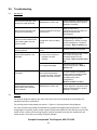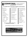
1
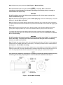
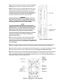
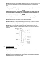
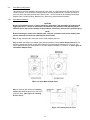
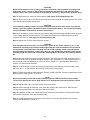
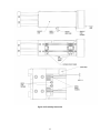
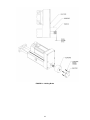
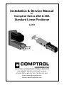
Installation & Service Manual
for
Comptrol Series 20A & 40A
Standard Linear Positioner
A-353
INDUSTRIAL AUTOMATION SYSTEMS & SERVICES
9505 MIDWEST AVENUE CLEVELAND, OH 44125
(216) 587-5200 or (800) 743-1952 FAX (216) 587-5210
Email: [email protected]
Website: www.comptrolinc.com
Table of Contents
1.0
Introduction
1.1
Warranty ...................................................................................................................Page 1
1.2
Limitations of Liability................................................................................................Page 1
1.3
Safety Considerations ..............................................................................................Page 1
1.4
Linear Positioner Overview.......................................................................................Page 2
1.4.1 Lubrication. ...............................................................................................................Page 3
1.4.2 Motor Options. ..........................................................................................................Page 3
1.4.3 Standard Options......................................................................................................Page 3
2.0
Installation - Mounting Configurations
2.1
General Safety and Mounting Considerations..........................................................Page 4
2.2
Standard Base Mount Configuration ........................................................................Page 4
2.3
Mounting Feet Option ...............................................................................................Page 5
2.4
Front Mount Option...................................................................................................Page 5
2.5
Clevis Mount Option .................................................................................................Page 6
2.6
Trunnion Mount Option.............................................................................................Page 6
3.0
Motor Installation and Removal
3.1
Parallel Motor Configuration .....................................................................................Page 7
3.1.1 Parallel Motor Installation .........................................................................................Page 7
3.1.2 Parallel Motor Removal….........................................................................................Page 10
3.2
Inline Motor Configuration ........................................................................................Page 11
3.2.1 Inline Motor Installation.............................................................................................Page 11
3.2.2 Inline Motor Removal................................................................................................Page 14
4.0
Optional Equipment
4.1
Home/Overtravel Sensor Kit Adjustment..................................................................Page 15
4.2
Holding Brake ...........................................................................................................Page 18
4.2.1 Holding Brake Removal............................................................................................Page 18
4.2.2 Holding Brake Installation.........................................................................................Page 18
4.3
Rotary Encoder.........................................................................................................Page 20
4.3.1 Rotary Encoder Removal .........................................................................................Page 20
4.3.2 Rotary Encoder Installation ......................................................................................Page 20
4.4
Holding Brake/Rotary Encoder .................................................................................Page 22
4.4.1 Holding Brake/Rotary Encoder Removal..................................................................Page 22
4.4.2 Holding Brake/Rotary Encoder Installation...............................................................Page 22
5.0
Startup ..................................................................................................................................Page 24
6.0
Maintenance & Service
6.1
Bushings & Shaft Seals ............................................................................................Page 24
6.2
Bearing .....................................................................................................................Page 24
6.3
Drive Train. ...............................................................................................................Page 25
6.4
Ballscrew Assembly..................................................................................................Page 25
6.4.1 Ballscrew Assembly Lubrication. ..............................................................................Page 25
7.0
Model Number Designation ................................................................................................Page 27
8.0
Formulas
8.1
Life Calculations .......................................................................................................Page 28
8.2
Thrust/Force and Linear Speed Calculations ...........................................................Page 28
8.3
Rotational Speed Ratings.........................................................................................Page 28
9.0
Troubleshooting
9.1
Mechanical ...............................................................................................................Page 29
9.2
Electrical ..................................................................................................................Page 29
1.0
Introduction
This manual provides information and procedures for installing, maintaining and servicing a standard
Comptrol Series 20A and 40A Linear Positioners or a unit equipped with standard options installed by or
available from Comptrol Incorporated. The procedures are to be performed by qualified technical
personnel in adherence with all safety regulations and precautions.
1.1
Warranty
Comptrol Incorporated warrants to the original buyer that the goods supplied hereunder, which are
manufactured by Comptrol Incorporated, will be free of defect in material and workmanship for one (1)
calendar year from the original date of shipment from Comptrol Incorporated to the original buyer.
Any disassembly or modification of the positioner, not covered in this manual will void the warranty and
may cause harm to personnel and/or equipment.
Operating the positioner at speeds or loads that exceed Comptrol published specifications will void the
manufacturer’s warranty and may cause harm to personnel and/or equipment. Please call Comptrol
Incorporated at 800-743-1952 if you have questions relative to speeds and/or acceptable loads for your
application.
1.2
Limitations of Liability
In no event will Comptrol Incorporated be liable for anticipated profits or incidental or consequential
damages suffered by the buyer. Comptrol Incorporated liability on any claim of any kind for any loss or
damage arising out of, connected with, or resulting from this publication, or from the performance or
breach thereof or from the design, manufacture, sale, delivery, resale, inspection, repair, operation or use
of any goods covered by or furnished under this publication will in no event exceed price allocable to the
goods or unit thereof which gives rise to the claim and shall terminate one (1) year after the date of the
shipment of such goods.
It is the user’s responsibility to identify and protect against all potential pinch points or hazardous
conditions.
All protective covers must be installed before and during operation.
1.3
Safety Considerations
As with any electro-mechanical device, safety should be considered during installation, maintenance, and
operation of a Comptrol Linear Positioner. While performing work listed in this manual, remove, lock out
and tag all sources of power, and remove or secure the load. Throughout this manual, the paragraphs
marked with WARNINGS, CAUTIONS, and NOTES provide information to ensure a safe and trouble free
installation and operation. Failure to comply or omit any step(s) in the procedure, unless specifically
instructed to do so in this manual, may cause personal injury or damage to equipment
.
This information contained in this document is subject to change without notice. Comptrol
Incorporated has made every effort to insure the accuracy and completeness of the descriptions and
procedures discussed in this document. Failure to comply with these procedures may result in
personal injury and/or damage to the Comptrol product and/or the equipment used in conjunction with
it. Comptrol Incorporated assumes no liability for incidental or consequential personal or equipment
damages arising from the use of this document, the software and hardware described, or the failure to
comply with any procedure contained in this document. Note that protective covers may not be shown
in some illustrations to provide a clearer view of specific components or assemblies. All protective
covers must be installed before and during operation of the unit.
© Copyright 2002 Comptrol Incorporated
Printed in U.S.A.
1
All Rights Reserved
A353-9-02
1.4
Linear Positioner Overview
Comptrol Series 20A and 40A Linear Positioners are designed to convert rotary motion into linear motion
and are available in either parallel or inline configurations.
The parallel configuration has the motor mounted on the inboard side of the positioner tower parallel to
the positioner body. A timing belt and pulley arrangement transmits the motor rotary torque to the
ballscrew. (See Figure 1: Parallel Drive Train Configuration) The inline configuration uses a flexible
coupling to connect the motor directly to the ballscrew. (See Figure 2: Inline Drive Train Configuration)
During operation, the rotating ballscrew drives the mating ballnut that is attached to the positioner load
flange to convert the rotary ballscrew motion to linear motion. The linear motion of the load flange is
transferred to the positioner load mounting plate by the two guide shafts that connect the load flange and
load mounting plate. (See Figure 3: Internal Positioner Construction)
WARNING
The guide shafts are designed to connect the load flange to the load mounting plate ONLY. The
guide shafts are NOT designed to replace a linear rail, round rail, dove tail way, box way, or any
other guide support assembly needed to guide and support the load being positioned. Using the
guide shafts in this manner can reduce life significantly and cause an increase in motor torque
due to side loading the guide shafts and ballscrew assembly.
CAUTION
If the surface of the guide shafts become dinged or severally scratched, the seal and bronze
bushings may be compromised causing contamination of the internal positioner components.
Figure 2: Inline Drive Train Configuration
Figure 1: Parallel Drive Train Configuration
Figure 3: Internal Positioner Construction
2
1.4.1
Lubrication
Comptrol Incorporated has an EXCLUSIVE lubricating method that delivers lubrication directly to the
ballscrew assembly. A zerk fitting (typical grease fitting) is installed in one of the 1/8 NPT ports in each
side of the load mounting plate for manually filling the lubrication delivery system to maintain lubricant on
the ballscrew assembly. The ports may also be used to connect to an automatic lubricating system. (See
Figure 4: Lubrication System).
WARNING
Comptrol lubricates each Linear Positioners at the factory during assembly with Dri-Slide brand
HDMP molybdenum disulfide lubricating grease, code 00343. The positioner does NOT need to be
lubricated after initial installation. However, it is the user's responsible to fill the lubrication
delivery system approximately every 200 operating hours to maintain adequate lubrication.
WARNING
Before using any lubricant other than Dri-Slide HDMP to lubricate the positioner ballscrew
assembly, contact Comptrol Incorporated 800-743-1952
Figure 4: Lubrication System
1.4.2
Motor Options
Comptrol Series 20A and 40A Linear Positioners are available with several types of motors including
Servo, Stepper, AC Synchronous, and variable speed DC motors. Series 20A positioners can be
configured for motors with frame sizes from 2.25 to 3.50 inches square (typically a NEMA 23C or 34C
frame). Series 40A positioners can be configured for motors with frame sizes from 4.00 inch to 5.00
inches square (typically a NEMA 42C, 56C, or 143C frame). A variety of planetary gearboxes are also
available for Comptrol Series 20A and 40A positioners.
Comptrol positioners are available with or without a factory-installed motor. If the motor is to be field
installed, Comptrol will provide a motor mounting kit for adapting the motor frame size specified at the
time of order. See Section 3.0 for motor installation and removal.
1.4.3
Standard Options
Comptrol standard base mount Series 20A or 40A Linear Positioners are available with a variety of
mounting options including mounting feet, front flange, clevis, or trunnion. (See Section 2.0) Other
options include a Home/Overtravel Sensor Kit, Holding Brake, and Encoder. (See Section 4.0)
3
2.0
Installation - Mounting Configurations
This section contains information relative to installing a standard base mount Series 20A or 40A Linear
Positioner or a positioner configured with one of the mounting feet, front flange, clevis, or trunnion options
available from Comptrol Incorporated.
2.1
General Safety and Mounting Considerations
WARNING
Failure to adhere to or comply with the following may result in damage to the Comptrol Linear
Positioner, machinery, and/or cause serious injury to personnel.
1. Before installing, maintaining or servicing the linear positioner or its components, remove,
lock out, and tag all potential sources of energy (electrical, mechanical, and pneumatic).
2. Secure or detach the load from the positioner load mounting flange before servicing or
making adjustments to the positioner or its components.
3. All load and structural mounting surfaces must be flat, parallel, and square to within .002 inch
of the positioner.
4. Excessive side loading will reduce the life of the positioner and should be avoided.
5. Use grade eight fasteners when mounting the Linear Positioner or attaching the load to the
load mounting plate. When threading into a tapped hole, the thread engagement should be at
least 1½ times the fastener diameter to insure proper and safe thread engagement.
6. DO NOT use the positioner body and/or tower as a support for other structures or mechanism.
7. It is the user's responsibility to identify and protect against all potentional pinch points and
hazardous conditions, and to insure that all safety devices and protective covers are installed
and functioning.
8. Insure that qualified personnel, proper tools, and lifting devices are available for safe handling
and installation of the positioner.
2.2
Standard Base Mount Configuration
Series 20A and 40A positioners have four 5/16-18 UNC heavy square nuts installed in the T-slots in the
bottom of the extruded body. The nuts may be positioned along the length of the T-slots for mounting the
positioner body to a base structure. Comptrol recommends that the square nuts be positioned a
maximum of 1/5 the length of the extruded body from each end. (See Figure 5: Base Mount)
Example: For a 9 inch long extrusion body, 9 * (1/5) = 1.8 inches maximum distance from each end.
Comptrol recommends securing the positioner to the mounting surface with grade eight 5/16-18
fasteners. The tightening torque specification for the 5/16-18 fasteners is 216-288 in-lb.
WARNING
The mounting fastener thread should extend 1/2 inch (± 1/16) beyond the mounting surface to
insure proper thread engagement and to avoid contact with the top of the T-slot.
Figure 5: Base Mount
4
2.3
Mounting Feet Option
The optional mounting feet are secured to the positioner body using the heavy square nuts in the T-slots
in the bottom of positioner body. (See Figure 5: Base Mount) The feet can be repositioned along the
length of the T-slots by loosening the mounting fasteners, sliding the feet to the proper position, and
retightening the mounting bolts. Comptrol recommends that the feet be positioned a maximum of 1/5 the
the length of the extruded body from each end. The tightening torque specification for the 5/16-18
mounting feet fasteners is 216-288 in-lb. (See Figure 6: Mounting Feet Option)
Example: For a nine inch long extrusion body, 9 * (1/5) = 1.8 inches maximum distance from each end.
A clearance holes for 5/16 inch diameter fastener are provided in the mounting feet for mounting the
positioner to a base a base structure. Comptrol recommends using grade eight fasteners for mounting
the Series 20A and 40A Linear Positioners. When threading into a tapped hole, the thread engagement
should be at least 1½ times the fastener diameter to insure proper and safe thread engagement.
Figure 6: Mounting Feet Option
2.4
Front Mount Option
The Comptrol Series 20A and 40A Linear Positioners are available with a front mount flange for face
mounting the unit to a machine support structure. Units with the front mount flange can be mounted
horizontally or vertically using the four mounting holes provided. (See Figure 7: Front Mount Option)
CAUTION
The front mount option reduces the available stroke length of a unit by .25 inch for a Series 20A
and .44 inch for a Series 40A. Series 20A positioners require four 5/16 diameter grade eight
fasteners. Series 40A positioners require four 3/8 diameter grade eight fasteners.
CAUTION
The front mount flange is designed to support a standard Comptrol Linear Positioner and motor
configuration operating safely within the published operating and load capacity specifications
(Series 20A – 870 lb., Series 40A - 1,830 lb.) for the unit. Modifying this configuration or exceeding
these specifications may damage the positioner and/or cause serious personal injury.
Figure 7: Front Mount Option
5
2.5
Clevis Mount Option
The clevis mount option is designed for applications requiring the positioner to pivot at both ends. The
clevis provides the pivot point at the rear of the positioner. A rod eye end can be installed in the 5/8-18
tapped hole in the load mounting plate to provide a pivot point for the front of the positioner. This will
allow the positioner to pivot about the two mounting points. (See Figure 8: Clevis Mount Option)
The clevis mount attaches to the pulley cover plate on the same center as the 5/8-18 tapped hole in the
load mounting plate. The pivot pin hole in the clevis mount is reamed (.500/.501 diameter) for mating with
the user-supplied hardened steel pin and mounting bracket. Comptrol recommends using a hardened
steel pin with a retainer at both ends to prevent the pin from falling out.
CAUTION
The clevis mount option is designed to support a standard Comptrol Linear Positioner and motor
configuration operating safely within the published operating and load capacity specifications
(Series 20A– 870 lb., Series 40A – 1,830 lb.) for the unit. Modifying this configuration or exceeding
these specifications can result in damage to the positioner and/or cause serious personal injury.
Figure 8: Clevis Mount Option
2.6
Trunnion Mount Option
The trunnion mount option is designed for applications requiring the positioner to pivot around one point.
The two .7500/.7495 inch diameter bearing journals, one on each side of the positioner body, mount in
the user-supplied bearing supports designed to support the unit. This allows the positioner to rotate or
pivot around the centerline of the bearing journals. (Figure 9: Trunnion Mount Option)
CAUTION
The trunnion mount option is designed to support a standard Comptrol Linear Positioner and
motor configuration operating safely at or under its specified load capacity (Series 20A – 870 lb.,
Series 40A – 1,830 lb.). Failure to comply with this specification may result in damage to the
positioner and/or cause serious personal injury.
Figure 9: Trunnion Mount Option
6
3.0
Motor Installation and Removal
3.1
Parallel Motor Configuration
This section covers the installation and removal of the motor on a Comptrol Series 20A and 40A Parallel
Linear Positioner. If the positioner is shipped without a factory installed motor, Comptrol will supply a
drive train kit for the motor specified at the time of order. The kit consists of the following items: Motor
Adapter Plate, Timing Belt, Ballscrew Pulley, Motor Pulley, Ballscrew Key, Motor Key, and associated
hardware.
NOTE
The kit is designed for a specific motor. Substituting a different motor for the one originally
specified, may require a new kit. Contact Comptrol Incorporated for assistance at 800-743-1952.
3.1.1
Parallel Motor Installation
CAUTION
Remove all potential sources of energy (electrical, mechanical, and pneumatic) by locking out &
tagging the source. Secure or detach the load attached to the positioner load mounting plate.
Failure to do so may result in damage to the positioner, machinery, and/or serious personal injury.
NOTE
Before mounting the motor to the motor adapter plate, verify the orientation of the motor adapter
plate and the motor electrical connectors for attaching the motor cables.
Step 1: Align and insert the motor pilot into the motor adapter pilot hole. (See Figure 10: Motor Adapter
Plates)
Step 2: Mount the motor to the adapter plate with the fasteners marked motor adapter fasteners. The
tightening torque specification for the Series 20A #10-32 motor adapter fasteners is 51-68 in-lb. The
torque specification for the Series 40A 5/16-18 motor adapter fasteners is 216-288 in-lb.
NOTE
If the optional brake and/or encoder is installed, refer to Section 4.0 for removal instructions
before proceeding.
Figure 10: Motor Adapter Plates
7
Step 3: Remove the pulley cover plate. (See Figure 12: Ballscrew Pulley)
NOTE
Most motor shafts require a key for mounting a pulley or coupling. Refer to the motor
manufacturer’s documentation for information pertaining to mounting a pulley or coupling to
motors that do not require a key.
WARNING
DO NOT modify the motor shaft. Most motor manufactures will void the motor warranty if the
motor is modified in any way.
Step 4: Install the Comptrol supplied key marked motor pulley key in the motor shaft keyway, if required.
(Figure 11: Parallel Motor Assembly)
Step 5: Comptrol recommends applying thread locking compound on the pulley set screws at assembly
(Comptrol recommends Loctite Threadlocker 222). Remove and reinstall the set screws after applying the
compound.
Step 6: With the pulley hub facing the motor, align the keyway in the Comptrol supplied motor pulley
(pulley without flanges) with the key on the motor shaft and slide the pulley onto the motor shaft.
For motors with a flat on the motor shaft instead of a keyway, orient the pulley so that the flat on the
motor shaft is directly under one of the two set screws in the motor pulley hub. (See Figure 13: Parallel
Drive Train Assembly)
WARNING
DO NOT substitute the Comptrol supplied set screws with a nylon insert (“Nylok”) or any fastener
that is self-locking. The pulleys are made from aluminum and the nylon insert or self-locking
fasteners can strip out the threads.
Step 7: Position the motor pulley to within 1/32 inch of the dimension shown in Figure 11 for the spacing
between the motor adapter plate and the motor pulley. The spacing will depend on the model positioner.
(See Figure 11: Parallel Motor Assembly)
Step 8: To lock the pulley on the motor shaft, tighten the two motor pulley set screws that are located 90°
apart in the pulley hub. The torque specification for the Series 20A #8-32 motor pulley set screw is 31-41
in.-lb. The torque specification for the Series 40A 1/4-20 motor pulley set screws is 108-144 in.-lb.
NOTE
If the motor to be installed is specified prior to shipment, Comptrol will install the ballscrew pulley
and timing belt assembly. Skip steps 8 thru 12 and continue the installation with Step 13.
Figure 11: Parallel Motor Assembly
8
Step 9: Install the Comptrol supplied key marked ballscrew
pulley key in the keyway on the ballscrew drive journal.
Step 10: There are two set screws located 90° apart in the
ballscrew pulley teeth (pulley with flanges). One is located
directly above the keyway in the pulley bore. Comptrol
recommends removing both set screws and applying thread
locking compound on the threads, then reinstalling them.
(Comptrol recommends Loctite Threadlocker 222.)
WARNING
DO NOT substitute the Comptrol supplied set screws
with nylon insert (“Nylok”) or any fastener that is selflocking. The pulleys are aluminum and nylon inserts or
self-locking fasteners can strip out the threads.
NOTE
The hub on the Series 20A ballscrew pulley must be
oriented outboard facing away from the front face of the
positioner tower. The Series 40A Positioner ballscrew
pulley does not have a hub and does not require any
hub orientation. (See Figure 12: Ballscrew Pulley)
The set screw holes in the ballscrew pulley hub should
not have set screws in them. If the set screws are
present, remove them.
Step 11: Orient the ballscrew pulley so that the keyway in
the pulley bore aligns with the key in the ballscrew drive
journal, and the set screw that is offset 90° aligns with the flat
on the ballscrew drive journal. (See Figure 13: Parallel Drive
Train Assembly)
Figure 12: Ballscrew Pulley
Step 12: Loop the timing belt around the ballscrew pulley and slide the pulley onto the ballscrew drive
journal. If necessary, rotate the pulley until one of the set screws in the pulley teeth is accessible.
Step 13: Position the pulley on the ballscrew journal so that there is 1/16 (±1/32) inch clearance between
the pulley flange and the front face of the positioner tower. (See Figure 12: Ballscrew Pulley)
Step 14: To lock the pulley onto the ballscrew journal, tighten one of the set screws located in the pulley
teeth, then rotate the pulley to access and tighten the other screw. The ballscrew pulley set screw
torque specifications for the Series 20A #8-32 set screws is 31-41 in.-lb. The torque specification for the
Series 40A 1/4-20 set screws is 108-144 in.-lb.
Figure 13: Parallel Drive Train Assembly
9
Step 15: Position the motor and motor adapter plate assembly on the linear positioner tower, making sure
that the timing belt is being looped around the motor pulley as the adapter plate is positioned on the
tower.
Step 16: Install and lightly tighten the motor adapter fasteners marked motor adapter fasteners without
applying any timing belt tension. Verify that the ballscrew and motor pulleys are aligned to within 1/32 of
an inch. (See Figure 14: Pulley Alignment)
CAUTION
If the pulleys are not aligned, check the spacing between the motor pulley and the adapter plate
(Step 5), and the ballscrew pulley flange and the tower (Step 15). If necessary, disassemble and
repeat Steps 3 thru 14 before continuing.
WARNING
DO NOT TENSION OR PRELOAD the timing belt. Improper belt tension can cause premature belt
wear, noise, slippage, and/or failure as well as premature failure of the motor bearings and
ballscrew assembly. Contact Comptrol Incorporated for information regarding proper belt
tensioning. 800-743-1952
Step 17: Support the motor and loosen the four motor adapter tower fasteners.
Step 18: Slide the motor up away from the ballscrew until the slack is taken up in the timing belt, then
tighten the four motor adapter fasteners. The torque specification for the Series 20A #10-32 motor
adapter fasteners is 51-68 in.-lb. The torque specification for the Series 40A 5/16-18 motor adapter
fasteners is 216-288 in.-lb. (See Figure 14: Pulley Alignment)
Step 19: Install the pulley cover plate and secure it to the tower with the six flat head pulley cover
fasteners. The torque specification for the Series 20A and 40A #10-32 pulley cover plate fasteners is
51-68 in.-lb.
Figure 14: Pulley Alignment
3.1.2
Parallel Motor Removal
Step 1: Remove the pulley cover
Step 2: Support the motor and loosen the motor adapter fasteners allowing the motor to slide down to
relieve tension on the timing belt.
Step 3: Support the motor and remove the motor adapter plate fasteners.
Step 4: Remove the motor, adapter plate, and motor pulley as one assembly allowing the timing belt to
slide off the motor pulley as the assembly is removed.
10
3.2
Inline Motor Configuration
This section covers the installation and removal of the motor on a Comptrol Series 20A and 40A Inline
Linear Positioner. If the positioner is shipped without a factory-installed motor, Comptrol will supply a
drive train kit for the motor specified at the time of order. The kit consists of the following items: Motor
Adapter Plate, Flexible Coupling, Ballscrew Key, Motor Key, and associated hardware.
3.2.1
Inline Motor Installation
CAUTION
Remove all potential sources of energy (electrical, mechanical, and pneumatic) by locking out &
tagging the source. Secure or detach the load attached to the positioner load mounting plate.
Failure to do so may result in damage to the positioner, machinery, and/or serious personal injury.
NOTE
Before mounting the motor to the adapter plate, verify the orientation of the motor adapter plate
and the electrical connectors for attaching the motor cables.
Step 1: Align and insert the motor pilot into the motor adapter pilot bore.
Step 2: Attach the motor to the adapter plate with the fasteners marked motor adapter fasteners. The
tightening torque specification for the Series 20A #10-32 motor adapter fasteners is 51-68 in.-lb. The
torque specification for the Series 40A 5/16-18 motor adapter fasteners is 216-288 in.-lb. (See Figure 15:
Inline Motor Adapter Plate)
Figure 15: Inline Motor Adapter Plate
Step 3: Unscrew and remove the coupling
access port cover located on the side of the
positioner body. (See Figure 16: Coupling
Access Cover)
Figure 16: Coupling Access Cover
11
Step 4: Insert the Comptrol supplied key marked ballscrew key in the keyway on the ballscrew drive
journal. (See Figure 18: Inline Drive Train Assembly)
Step 5: Align the keyway in the flexible coupling bore with the key on the ballscrew drive journal and slide
the coupling onto the journal. Make sure the coupling slides onto the ballscrew journal and key without
binding. Do not tighten the flexible coupling clamp screw.
Step 6: To orient the ballscrew for final assembly of the coupling onto the ballscrew journal, check that
the head of the flexible coupling clamp screw is visible and accessible through the coupling access port. If
it is not, grip the coupling and rotate the coupling and ballscrew until the head of the screw is visible and
accessible.
Step 7: Slide the coupling off the drive journal.
Step 8: Install the Comptrol supplied key marked motor pulley key into the keyway in the motor shaft.
NOTE
Most motor shafts require a key for mounting a pulley or coupling. Refer to the motor
manufacturer’s documentation for information pertaining to mounting a pulley or coupling to
motors that do not require a key.
WARNING
DO NOT modify the motor shaft. Most motor manufacturers will void the motor warranty if the
motor is modified in any way.
Step 9: Check that the flexible coupling slides onto the motor shaft key without binding.
Step 10: Comptrol recommends applying thread locking compound on the coupling clamping screws at
assembly (Comptrol Incorporated recommends Loctite Threadlocker 222). Remove and reinstall the set
coupling clamp screws after applying the compound.
Step 11: Align the keyway (if required) in the coupling bore with the key in the motor shaft, and slide the
flexible coupling onto the motor shaft. The end of the motor shaft should be even with the end of the bore
in the motor half of the flexible coupling hub. (See Figure 17: Inline Motor Assembly)
WARNING
Make sure the motor shaft DOES NOT protrude into the elastomer center section of the flexible
coupling or rub on the face of the other half of the hub. This will decrease the life of the coupling.
Step 12: Tighten the flexible coupling clamp screw to lock the coupling on the motor shaft. The torque
specification for Series 20A #8-32 flexible coupling clamp fastener is 31-41 in.-lb. The torque specification
for the Series 40A #10-32 clamp fastener is 51-68 in.-lb.
Figure 17: Inline Motor Assembly
12
Step 13: Grip and rotate the coupling to rotate the motor shaft so that the keyway in the coupling bore is
oriented to align with the key on the ballscrew drive journal. Make sure the motor electrical connectors are
properly oriented.
Step 14: Slide the inline motor assembly (motor, adapter plate, and coupling) into the positioner while
orienting the motor so that the coupling keyway slides over with the key on the ballscrew drive journal.
The motor adapter plate pilot will align with the tower pilot hole when the motor is seated properly. (See
Figure 18: Inline Drive Train Assembly)
Step 15: Install the four mounting fasteners marked motor adapter tower fasteners into the inline tower.
The torque specification for the Series 20A #10-32 motor adapter fasteners is 51-68 in.-lb. The torque
specification for the Series 40A 5/16-18 motor adapter fasteners is 216-288 in.-lb. (See Figure 18: Inline
Drive Train Assembly)
Step 16: Access the flexible coupling clamp screw through the coupling access port, and tighten the
clamp fastener to lock the coupling on the ballscrew drive journal. The flexible coupling clamp fastener
torque specifications for Series 20A #8-32 fastener is 31-41 in.-lb. The torque specification for the Series
40A #10-32 fastener is 51-68 in.-lb. (See Figure 18: Inline Drive Train Assembly)
Step 17: Install coupling access port cover.
Figure 18: Inline Drive Train Assembly
13
3.2.2
Inline Motor Removal
Step 1: Unscrew and remove the flexible coupling access port cover.
Step 2: Check if the head of the flexible coupling clamp screw is visible and accessible. If it is not, rotate
the ballscrew until the clamp fastener head is visible and accessible.
Step 3: Loosen the coupling clamp fastener.
Step 4: Support the motor and remove the motor adapter plate fasteners.
Step 5: Continue to support the motor, and slide the coupling off the key in the ballscrew journal to
remove the motor and motor adapter plate assembly from the positioner tower.
NOTE
If the ballscrew cannot be rotated manually,
1. Support the motor and remove the motor adapter fasteners.
2. Pull out on the motor to separate the two halves of the flexible coupling. The flexible
coupling is a two-piece spider coupling with the two halves of the coupling press fit
together.
3. Grip and rotate the coupling half attached to the ballscrew journal to rotate the ballscrew
until the head of the coupling clamp fastener is visible and accessible through the flexible
coupling access port.
4. Loosen the fastener and slide the half of the coupling on the ballscrew off the key in the
ballscrew journal.
5. Press the two halves of the coupling back together.
14
4.0
Optional Equipment
4.1
Home/Overtravel Sensor Kit Adjustment
The Home/Overtravel Sensor Kit is a factory-installed option with three adjustable proximity sensors
consisting of one home sensor, and two overtravel sensors (plus=extend and negative=retract).
The proximity sensors are four wire 10-30 VDC sensors. Depending on how they are wired to the
controller, each sensor may be configured as Normally Open or Normally Closed and PNP (Source) or
NPN (Sink). (See Figure 19: Proximity Sensor Wiring Diagram)
Figure 19: Proximity Sensor Wiring Diagram
15
CAUTION
Remove all potential sources of energy (electrical, mechanical, and pneumatic) by locking out &
tagging the source. Secure or detach the load attached to the positioner load mounting plate.
Failure to do so may result in damage to the positioner, machinery, and/or serious personal injury.
Step 1: Remove the four sensor kit cover fasteners. (See Figure 20: Proximity Sensor Kit)
Step 2: As you remove the cover, feed the proximity sensor wires through the rubber grommet. Be careful
not to damage the proximity sensor wires.
CAUTION
The overtravel proximity sensors are set for maximum travel and the home sensor is positioned
directly next to the negative (retracted) overtravel sensor at the factory. The overtravel proximity
sensors should be set at the end of actual required travel.
Step 3: To reposition a sensor, loosen the two proximity bracket fasteners and slide the bracket along the
T-slot. Tighten proximity bracket fasteners. The torque specification for the #10-32 proximity bracket
fasteners is 51-68 in.-lb. (See Figure 20: Proximity Sensor Kit)
Step 4: Repeat Step 3 for the other sensors if required.
CAUTION
After repositioning the sensor(s), it is necessary to check for the proper clearance (.04” +/- .01)
between the proximity sensor and proximity target. Improper clearance between the sensor and
the target may cause interference resulting in the tip of the proximity sensor being sheared off
when operating the positioner. If there is too large of a gap between the proximity sensor and the
proximity target, the sensor will not detect the proximity target. (See Figure 20: Proximity Sensor
Kit.
Step 5: Manually position the target opposite the sensor. This will require removing the pulley cover to
access the motor pulley on positioners with the parallel motor configuration, or removing the motor on inline models to access the ballscrew drive journal. Refer to Section 3.1.2 (Parallel Motor Removal) or
Section 3.2.2 (Inline Motor Removal).
Step 6: To adjust the gap, loosen the proximity clamp fasteners and slide the proximity sensor so that
there is a .04” +/- .01 gap between the proximity sensor and proximity target.
Step 7: Tighten the proximity clamp fasteners. DO NOT OVER TIGHTEN. The torque specification for the
#6-32 Proximity clamp screw is 17-23 in-lb.
NOTE
When the proximity sensor detects the proximity target, the LED located where the proximity
sensor wires attach to the sensor body will turn on or off depending on how the sensor is wired.
Step 8: Repeat Steps 5 thru 7 for each sensor before proceeding
Step 9: Before replacing the sensor kit cover check the routing of the sensor wires. Make sure the
moving proximity target does not pinch any of the sensor wires.
Step 10: Install the sensor cover making sure all the sensor wires are routed to clear all possible pinch
point between the sensor cover and positioner body.
Step 11: Install and tighten the four sensor cover fasteners. The torque specification for the #10-32
sensor cover fasteners is 51-68 in-lb.
16
Figure 20: Proximity Sensor Kit
17
4.2
Holding Brake
The optional factory-installed holding brake is a 24 volt DC electrically released spring set brake designed
for applications where the load is capable of back driving the ballscrew when power to the motor drive is
removed. When the brake is energized, the ballscrew is allowed to rotate freely. If power is removed
either deliberately or because of power failure, the spring sets the brake to safely hold the load stationary.
The splined hub of the holding brake is keyed on the ballscrew journal and secured with two set screws.
CAUTION
The standard Comptrol Series 20A and 40A Linear Positioner holding brake is capable of
HOLDING 200 pounds without being back driven. The holding brake is a static brake and is
engaged whenever the positioner is not moving. It should never be used as a dynamic brake and
should NEVER be energize while the positioner is operating.
For the optional brake module to convert 120 or 240 volt AC to 24 volt DC call Comptrol Incorporated at
800-743-1952.
4.2.1
Holding Brake Removal
CAUTION
Remove all potential sources of energy (electrical, mechanical, and pneumatic) by locking out &
tagging the source. Secure or detach the load attached to the positioner load mounting plate.
Failure to do so may result in damage to the positioner, machinery, and/or serious personal injury.
Step 1: Disconnect the cable(s) supplying the 24-volt DC power to the brake.
Step 2: Remove the four #8-32 holding brake mounting fasteners that attach the brake cover and holding
brake to the pulley cover and slide the holding brake off the splined hub. (See Figure 21: Holding Brake)
CAUTION
If it is necessary to remove the splined hub from the ballscrew journal, measure the distance from
the pulley cover to the end of the splined hub. This distance will be about 1/32 of an inch less
than the width of the holding brake ONLY. When the holding brake is mounted to the pulley
cover, the splined hub should be 1/32 of an inch inside the holding brake housing. This alignment
allows proper engagement of the splined hub in the holding brake. (See Figure 21: Holding Brake)
Loosen the two set screws located 90° apart on the splined hub, and slide the hub off the ballscrew
journal. The hub is keyed to the ballscrew journal to prevent it from slipping.
4.2.2
Holding Brake Installation
CAUTION
Remove all potential sources of energy (electrical, mechanical, and pneumatic) by locking out &
tagging the source. Secure or detach the load attached to the positioner load mounting plate.
Failure to do so may result in damage to the positioner, machinery, and/or serious personal injury.
Step 1: If the splined hub was removed from the ballscrew journal, position the hub on the journal 1/32 of
an inch less than the width of the holding brake. Tighten the two set screws to secure the hub to the
ballscrew journal. The torque specification for the splined hub #4-40 set screws is 9-12 in.-lb. (See Figure
21: Holding Brake)
Step 2: Slide the brake onto the hub engaging the teeth in the brake with the splined hub. Rotate the
brake housing to align the mounting holes in the brake housing with the threaded brake mounting holes in
the positioner pulley cover. Make sure the electrical connectors are accessible and properly oriented.
Step 3: Position the brake cover on the end of the brake housing and insert the holding brake mounting
fasteners through the brake cover and housing and screw them into the threaded holes in the pulley
cover. The torque specification for the Series 20A and 40A #8-32 holding brake mounting fasteners is
31-41 in-lb.
Step 5: Connect the holding brake cable.
18
FIGURE 21: Holding Brake
19
4.3
Rotary Encoder
The rotary encoder option provides closed loop operation for position verification. The encoder is coupled
directly to the ballscrew journal for measuring precise positional accuracy. Your encoder may physically
appear different due to the particular application needs.
For rotary encoder wiring details see the encoder wiring diagram accompanying the Comptrol linear
positioner documentation. If a new wiring diagram is required, please contact Comptrol Incorporated at
800-743-1952 with the rotary encoder model number. Rotary encoder wiring diagrams must be
requested for the specific manufacture and model number. This is due to the variety of available options
on encoders.
4.3.1 Rotary Encoder Removal
CAUTION
Remove all potential sources of energy (electrical, mechanical, and pneumatic) by locking out &
tagging the source. Secure or detach the load attached to the positioner load mounting plate.
Failure to do so may result in damage to the positioner, machinery, and/or serious personal injury.
CAUTION
The encoder should be handled with care to prevent damaging the internal glass scale.
Step 1: Disconnect the encoder cable from rotary encoder.
Step 2: Loosen the flexible coupling clamp screw that secures the flexible coupling to the ballscrew
journal. The screw is accessible through the opening in the side of the encoder adapter. (See Figure 22:
Rotary Encoder)
NOTE
If the head of the screw is not accessible, support the encoder assembly and remove the encoder
adapter mounting fasteners. Then rotate the adapter/encoder assembly until the screw head is
accessible, loosen the clamp screw, and slide the adapter, encoder, and flexible coupling off as
one assembly. Proceed with Step 5.
Step 3: Remove the encoder adapter mounting fasteners.
Step 4: Slide the encoder adapter, encoder, and flexible coupling off as one assembly.
Step 5: Remove the encoder mounting fasteners and slide the encoder out of the piloted encoder
adapter.
NOTE
If the flexible coupling has to be removed from the encoder shaft, measure and record the
position of the coupling with respect to the encoder mounting face.
4.3.2
Rotary Encoder Installation
CAUTION
Remove all potential sources of energy (electrical, mechanical, and pneumatic) by locking out &
tagging the source. Secure or detach the load attached to the positioner load mounting plate.
Failure to do so may result in damage to the positioner, machinery, and/or serious personal injury.
NOTE
If the flexible coupling was removed from the encoder shaft, slide the coupling on the shaft to the
position recorded during disassembly, and tighten the flexible coupling clamp screw to secure the
coupling to the encoder shaft. If this distance was not recorded during disassembly, position the
flexible coupling on the encoder shaft so that the flexible clamp screw will be accessible through
the encoder adapter access hole when the encoder is reassembled to the encoder adapter. This
will allow for proper coupling engagement on the ballscrew coupling journal.
20
Step 1: Align the flexible coupling clamp screw with the access opening in the side of the encoder
adapter, and slide the encoder into the adapter pilot hole.
Step 2: Install the encoder mounting fasteners. The torque specification for the Series 20A and Series
40A #8-32 encoder mounting is 31-41 in.-lb.
Step 3: Slide the encoder/adapter assembly onto the ballscrew journal and tighten the coupling clamp
screw.
Step 4: Align the mounting holes in the encoder adapter with the positioner pulley cover encoder adapter
mounting holes and install the encoder adapter mounting fasteners. The tightening torque for the Series
20A and Series 40A #8-32 encoder adapter mounting fasteners is 31-41 in-lb.
Step 5: When the positioner is mounted in the proper location, connect the encoder cable.
Figure 22: Rotary Encoder
21
4.4
Holding Brake/Rotary Encoder
Comptrol Linear Positioners can be configured with the holding brake and encoder options mounted in
tandem to the positioner pulley cover.
NOTE
The encoder adapter mounted between the brake and encoder replaces the standard brake cover.
4.4.1
Holding Brake/Rotary Encoder Removal
CAUTION
Remove all potential sources of energy (electrical, mechanical, and pneumatic) by locking out &
tagging the source. Secure or detach the load attached to the positioner load mounting plate.
Failure to do so may result in damage to the positioner, machinery, and/or serious personal injury.
CAUTION
Handle the encoder with care to prevent damaging the internal glass scale.
Step 1: Disconnect the brake and encoder cables from the brake and encoder.
Step 2: Loosen the coupling clamp screw that secures the flexible coupling to the ballscrew journal. The
screw is accessible through the access hole in the side of the encoder adapter. (See Figure 23: Holding
Brake/Rotary Encoder)
NOTE
If the head of the flexible coupling clamp screw is not accessible,
a) Support the brake/encoder assembly and remove the encoder adapter/holding brake
mounting fasteners.
b) Rotate the encoder adapter/encoder assembly until the screw head is accessible.
c) Loosen the clamp screw, and slide the encoder adapter and encoder assembly off the
ballscrew journal.
d) Slide the holding brake off the splined hub on the ballscrew journal.
e) Proceed with Step 4.
Step 3: Support the encoder, adapter, and holding brake assembly and remove the encoder adapter and
hold brake mounting fasteners.
CAUTION
The encoder/adapter assembly may separate from the holding brake when removing the
assembly.
Step 4: Slide the holding brake, encoder adapter, encoder off as one assembly. (See Figure 23: Holding
Brake/Rotary Encoder)
4.4.2
Holding Brake/Rotary Encoder Installation
CAUTION
Remove all potential sources of energy (electrical, mechanical, and pneumatic) by locking out &
tagging the source. Secure or detach the load attached to the positioner load mounting plate.
Failure to do so may result in damage to the positioner, machinery, and/or serious personal injury.
CAUTION
The encoder should be handled with care to prevent damaging the internal glass scale.
NOTE
The encoder adapter replaces the standard brake end cover. If installing a new brake, remove the
cover.
For rotary encoder wiring details refer to the encoder wiring diagram accompanying the linear positioner
documentation. If a new wiring diagram is required, please contact Comptrol Incorporated at 800-7431952 with the rotary encoder model number. Rotary encoder wiring diagrams must be requested by the
specific manufacture and model number. This is due to the variety of available options on encoders.
22
Step 1: Slide the holding brake onto the ballscrew journal orienting the brake so that it engages the
splined hub on the ballscrew journal. (See Figure 23: Holding Brake/Rotary Encoder)
Step 2: Rotate the brake housing to align the mounting holes in the brake housing with the mounting
holes in the positioner pulley cover. Make sure the brake electrical connections are accessible and
oriented properly.
Step 3: If the encoder was removed from the encoder adapter, reassemble the encoder to the encoder
adapter with the encoder adapter fasteners. Orient the encoder adapter and encoder so that the flexible
coupling screw access hole is in the 9 o'clock position (as viewed looking from the encoder end of the
positioner) and the encoder electrical connection is accessible and oriented properly.
Step 4: If necessary, rotate the encoder flexible coupling so that the head of the flexible coupling clamp
screw is accessible through the opening.
Step 5: Slide the encoder and adapter assembly onto the ballscrew journal.
Step 6: Insert the encoder adapter/holding brake fasteners through the adapter flange and brake housing
and screw them into the positioner pulley cover. The torque specification for the Series 20A and Series
40A #8-32 encoder adapter/holding brake fasteners is 31-41 in-lb.
Step 7: Tighten the flexible coupling clamp screw.
Step 8: When the positioner is mounted in the proper position, connect the encoder and holding brake
electrical cables.
Figure 23: Holding Brake/Rotary Encoder
23
5.0
Startup
Comptrol Linear Positioners are assembled and shipped to meet the configuration and application
requirements specified at the time of order. Refer to the appropriate section(s) of this manual for the
necessary installation and adjustment procedures before proceeding.
CAUTION
Comptrol recommends running the positioner without the load attached to the positioner to verify
all programmed, mechanical, and electrical interfaces with respect to the application.
CAUTION
The front mount option reduces the available stroke length of a unit by .25 inch for a Series 20A
and .44 inch for a Series 40A. The proximity sensor kit reduces the overall available stroke length
of the Comptrol Series 20A and 40A Linear Positioner by one inch.
Before operating a Comptrol Linear Positioner after initial installation or performing maintenance or
service:
1. Insure all electrical cables are routed properly, secured, and will not interfere with the operation of
the positioner.
2. Check that the positioner is properly installed and secured to the mounting structure.
3. Verify that all mechanical and/or electrical overtravel, limit, feedback, and safety devices are
installed and functioning properly.
4. Refer to the control manufacturer's documentation for proper installation, startup, and operating
procedures.
5. Install all protective covers and guarding.
6. Refer to Section 8 of this manual for the formulas to calculate life, thrust/force, and rotational
speed for the linear positioner based on the required application operating parameters.
After running the positioner without the load attached, attach the load to the positioner and adjust the
system operating parameters to meet the application requirements.
6.0
Maintenance & Service
6.1
Bushings & Shaft Seals
The Comptrol Series 20A and 40A Linear Positioner guide shafts are aligned by self-lubricated bronze
bushings with seals to keep contaminates out and lubrication in.
WARNING
The guide shafts are designed to connect the load flange to the load mounting plate ONLY. The
guide shafts are NOT designed to replace a linear rail, round rail, dove tail way, box way, or any
other guide support assembly. Using the guide shafts in this manner can reduce life significantly
and cause an increase in motor torque due to side loading the guide shafts and ballscrew
assembly. (See Figure 24: Internal Positioner Components)
6.2
Bearing
Comptrol Series 20A and 40A Linear
Positioners incorporate a sealed
double row angular contact bearing
to support the drive end of the
ballscrew assembly. The bearing is
lubricated for life and requires no
maintenance under normal operating
conditions. (See Figure 24: Internal
Positioner Components)
Figure 24: Internal Positioner Components
24
6.3
Drive Train
Comptrol Series 20A and 40A Linear Positioners are available with either a parallel or an inline drive train
configuration. Under normal operating conditions, the timing belt, pulleys, and inline flexible coupling
associated with these configurations are not considered wear items. Under normal conditions, these
components should last the life of the positioner. (See Figure 25: Inline and Parallel Drive Train
Configurations)
Figure 25: Inline and Parallel Drive Train Configurations
6.4
Ballscrew Assembly
The ballscrew assembly located inside the positioner body cannot be visually inspected for damage or
wear. However, unusual or excessive noise, vibration, loss of motion, or positioning inaccuracy may
indicate a worn or damaged ballscrew assembly. If any of these conditions exists, contact Comptrol
Incorporated at 800-743-1952.
6.4.1
Ballscrew Assembly Lubrication
The ballscrew assembly is the only positioner component that requires periodic lubrication to maintain a
thin film of lubricant on the ballscrew.
WARNING
Operating the positioner with no lubrication will reduce operational life by 90%.
WARNING
Comptrol lubricates each Linear Positioners at the factory during assembly with Dri-Slide brand
HDMP molybdenum disulfide lubricating grease, code 00343. The positioner does NOT need to be
lubricated before using it for the first time. However, it is the user's responsible to insure that the
ballscrew assembly is lubricated before operating the positioner and to fill the lubrication delivery
system approximately every 200 operating hours to maintain adequate lubrication.
WARNING
Never mix lubricants of any type. Mixing the chemical additives of different lubricants may cause
undesirable results and void the warranty. Before using any lubricant other than Dri-Slide HDMP
to lubricate the positioner ballscrew assembly, contact Comptrol Incorporated 800-743-1952 .
CAUTION
Before manually lubricating or checking for proper lubrication of the positioner remove or secure
the load and remove all potential sources of energy (electrical, mechanical, and pneumatic) by
locking out & tagging the source. Failure to do so can result in damage to the positioner,
machinery, and/or cause serious personal injury
25
Comptrol Series 20A and 40A Linear Positioners feature an EXCLUSIVE lubricating method that delivers
lubrication directly to the ballscrew assembly. A zerk fitting (typical grease fitting) is installed in one of the
1/8 NPT ports located on each side of the load mounting plate for manually filling the lubrication delivery
system to lubricate the ballscrew assembly. These ports may also be used to connect to an automatic
lubricating system. The screw-type ballscrew inspection port cover on the side of the positioner body can
be removed to visually inspection the ballscrew lubrication. (See Figure 26: Ballscrew Assembly
Lubrication)
Depending on the stroke of the positioner, 2 to 4 grams (2 to 4 pumps from a standard grease gun) may
be required to maintain adequate lubrication. Lubricate the positioner at mid stroke, this will help to
spread the lubrication evenly along the ballscrew. The ballscrew should be kept coated with a thin film of
light grease to provide satisfactory operation under normal conditions.
WARNING
Too much grease can cause the balls in the ballnut to skid instead of rotate, which will greatly
decrease life and performance.
Figure 26: Ballscrew Assembly Lubrication
26
7.0
Model Number Designation
Example: P 20A – 09 40 C – B 3 C N
(1) (2)
(3) (4) (5) (6) (7) (8) (9)
(1) Configuration
P = Parallel
I = Inline
(2) Series
20A = Series 20A
40A = Series 40A
(3) Stroke Length
05 = 5 inches (All)
09 = 9 inches (All)
13 = 13 inches (All)
19 = 19 inches (All)
25 = 25 inches (All)
31 = 31 inches (40A only)
37 = 37 inches (40A only)
(4) Motors
00 = No Motor (customer supplied)
30 = Comptrol supplied stepper
40 = Comptrol supplied servo
99 = Other
(5) Drive Ratios
A = 1:1 (All)
B = 1.5:1 (40A parallel only)
C = 2:1 (20A parallel only)
(6) Mounting Style
`
A = Mounting Feet (In-Line only)
B = Mounting Feet (Parallel only)
C = Front Mount Flange
D = Clevis (Parallel only)
(7) Sensor Kit
0 = None
3 = Home/Overtravel Sensor kit
(8) Brake & Encoder
N = None
A = Servo Encoder
B = Cube Encoder
C = Servo Encoder with Brake
D = Cube Encoder with Brake
E = Brake
(9) Special
N = None
S = Special Modifications Required – Not Designated in (3) through (8)
27
8.0
Formulas
8.1
Life Calculations
The life of the ballscrew in a Comptrol Series 20A and 40A Linear Positioner is expressed as the linear
travel distance that 90% of the ballscrews are expected to meet or exceed before experiencing signs of
wear. Use the following formula to calculate ballscrew life.
L = (C / F) 3 x 10 6
L = Life in inches
C = Rated Dynamic Load Capacity (lb.) (20A = 1000 lb.) (40A = 3,450 lb.)
F = Equivalent Operating Load (lb.)
8.2
Thrust/Force and Linear Speed Calculations
Comptrol Series 20A and 40A Linear Positioners have a maximum thrust/force specification. The Series
20A Linear Positioner is rated for 870 pounds of thrust/force. The Series 40A Linear Positioner is rated for
1,830 pounds of thrust/force.
Thrust/Force (lbs.) = (2πNT / L) x E
N = Reduction Ratio
T = Torque (in.-lbs.)
L = Ballscrew Lead (in.) (.500 on standard 20A and 40A)
E = Efficiency (.90)
The linear speed that the Comptrol Series 20A and 40A Linear Positioner will produce at the load
mounting plate is a function of rotational speed of the ballscrew shaft and the ballscrew lead. It is
important to include any gearbox reduction and or drive train belt and pulley reduction into this equation
as well. Use the following formula to calculate linear speed.
V = nL
V = Linear Speed (in./sec.)
n = Rotational Speed of the Ballscrew (rev./sec.)
L = Ballscrew Lead (in.) (.500 on standard 20A and 40A)
Rotational Speed Ratings
The Comptrol Series 20A and 40A Linear
Positioners have a maximum rotational speed.
This rating is based on the critical speed of the
ballscrew (Rotational speed of the ballscrew
shaft that produces resonant vibrations of the
ballscrew) and the maximum allowed ball
velocity in the ballnut. (See Figure 27:
Rotational Speed Ratings)
Critical Speed
Rotational Speed (RPM)
8.3
The MAXIMUM allowed rotational ballscrew
shaft speed for a Comptrol Series 20A and
40A Linear Positioner is 41 rev./sec. (2500
RPM). This 2500 RPM limit is applicable for a
Series 20A with a 5 to 19 inch stroke and a
Series 40A with a 5 to 25 inch stroke. For
Comptrol Series 20A Linear Positioners with
over a 19-inch stroke and 40A Linear
Positioners with over a 25-inch stroke refer to
the following RPM/Stroke graph. (See Figure
27: Rotational Speed Ratings)
2,500
2,400
2,300
2,200
2,100
2,000
1,900
1,800
1,700
1,600
1,500
19.00
25.00
31.00
37.00
Stroke (in.)
20A
40A
Figure 27: Rotational Speed Ratings
28
9.0
Troubleshooting
9.1
Mechanical
Symptom/Problem
9.2
Possible Cause
Problem Solution
Abnormally loud whining noise
coming from inside positioner.
Misalignment or Side Load.
Check alignment of positioner with
load and load supports or guides.
Realign if necessary.
Abnormally loud whining noise
coming from the positioner.
Incorrect motor/drive tuning or
motion profile
Refer to motor/ drive
manufacturer's documentation for
proper procedures and
specifications.
Positioner motor rotates but the
load mounting plate does not
extend or retract.
Timing belt or inline coupling
failure.
Inspect timing belt (parallel
configuration) or flexible coupling
(inline configuration). Replace if
necessary. Refer to section 3.0
Excessive motor current to
operate positioner.
Ballscrew or thrust bearing
failure.
Consult Comptrol Incorporated.
Physical index position is not
repeatable
1) Loose pulley, inline drive
coupling or encoder
coupling.
Disconnect power to motor, Check
set screws on pulleys and
clamping fasteners on the
couplings. Refer to section 3.0 &
4.0
2) Timing belt damaged.
Disconnect power to motor,
replace timing pulley. Refer to
Section 3.0
Lost Motion
Worn ballscrew assembly.
Loose timing pulley, inline drive
coupling or encoder coupling.
Mounting plate and support
shafts vibrate when extended
and/or retracted.
Misalignment or Side Load.
Consult Comptrol Incorporated.
Check pulley set screws (parallel
configuration) and flexible
clamping screw (inline
configuration).
Refer to sections 3.0 & 4.0
Check alignment of positioner with
load and load supports or guides.
Realign if necessary.
Electrical
For electrical problems related to the motor and/or drive refer to the manufactures documentation for
applicable motor/drive combination.
For proximity sensor wiring details see section 4.1 Figure 19: Proximity Sensor Wiring Diagram.
For rotary encoder wiring details see attached wiring diagram that shipped with the positioner. If a new
wiring diagram is required, please contact Comptrol Incorporated at 800-743-1952 with the rotary encoder
model number. Rotary encoder wiring diagrams must be requested for the specific manufacturer and
model number. This is due to the variety of options available.
Comptrol Incorporated Tech Support: 800-743-1952
29
9505 Midwest Avenue Cleveland, OH 44125
216-587-5200
Fax: 216-587-5210
Email: [email protected]
Website: www.comptrolinc.com
Your Single Source of Automation & Motion Control Solutions
Control & Monitoring Systems
Motion Control
• Ballscrew Assemblies
• Counters & Rate Meters
• Linear & Rotary Encoders
• Bearing Blocks
• Clutches & Brakes
• Machine Control Systems
• Motor Control Centers
• Couplings
• Open I/O Networks
• Gearheads
• Linear Actuators
• Linear Guide Systems
• Linear Slides & Components
• Motors & Drives
• AC Synchronous
• Adjustable Frequency
• AC & DC
• Sequential
• Gear
• Servo
• Linear
• Stepper
• Operator Interfaces
• PLCs
• Power Monitoring Systems
• Production Monitors
• Relays & Times
Electronic Interface Devices
• Cable & Wire Seals & Transits
• Circuit Breakers & Protection
• Power Supplies
• Pushbuttons
• Signal Conditioning
• Terminal Blocks
Sensors & Switches
• Foot, Limit, Safety
• Photoelectric & Proximity
• Temperature Controls
• Scanners (Color, Distance,
Luminescence)
• Vision Systems
• Ultrasonic
• Web Tension Control
Safety Controls
• Weight Verification Systems
• Light Curtains
• Positioning Systems
• Rodless Actuators
• Interlocks & Interfaces
• Machine Guarding
• Area & Perimeter Guarding
Engineering, Panel Building, Machine Shop,
& Assembly Services Available
• Safety Mats
An ISO 9001 Registered Company Serving Industry Since 1952
Comptrol 53,000 square foot facility in Cleveland, Ohio houses sales, engineering, and
manufacturing operations