1
G1000 System Maintenance Manual
Diamond DA 40 & DA 40 F
Including GFC 700 or KAP 140 AFCS
Contains FAA-Accepted Instructions
For Continued Airworthiness For
STC SA01444WI-D
190-00545-01
February 2013
Revision G
© Copyright 2008 - 2013
Garmin Ltd. or its subsidiaries
All Rights Reserved
Except as expressly provided herein, no part of this manual may be reproduced, copied, transmitted,
disseminated, downloaded or stored in any storage medium, for any purpose without the express prior
written consent of Garmin. Garmin hereby grants permission to download a single copy of this manual
and of any revision to this manual onto a hard drive or other electronic storage medium to be viewed and
to print one copy of this manual or of any revision hereto, provided that such electronic or printed copy of
this manual or revision must contain the complete text of this copyright notice and provided further that
any unauthorized commercial distribution of this manual or any revision hereto is strictly prohibited.
Garmin International, Inc.
1200 E. 151st Street
Olathe, KS 66062 USA
Telephone: 913-397-8200
www.garmin.com
Garmin (Europe) Ltd.
Liberty House
Bulls Copse Road
Hounsdown Business Park
Southampton, SO40 9RB, UK
Phone: +44 (0) 23 8052 4000
Fax: +44 (0) 23 8052 4004
RECORD OF REVISIONS
Revision Revision Date
B
1/03/2008
C
3/28/2008
D
4/8/2008
E
5/04/09
F
11/12/10
G
2/14/13
Description
Update for Phase 7: Add KAP 140 alignment &
update FAR 91.411 & Appendix E testing.
General updates throughout where noted.
Update for minor change to STC
Update for minor change to STC to add software
0321.19.
Update for major change to STC to add software
0321.22
Add Clarification to fuel probe re-calibration
procedures.
Update for major change to STC to add software
0321.23 and hardware upgrades.
ECO #
51022
52069
52347
58693
76686
99113
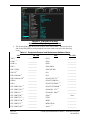
DOCUMENT PAGINATION
Section
Table of Contents
Section 1
Section 2
Section 3
Section 4
Section 5
Section 6
Section 7
Section 8
Page A
Revision G
Pagination
i – viii
1-1 – 1-16
2-1 – 2-18
3-1 – 3-48
4-1 – 4-40
5-1 – 5-62
6-1 – 6-16
7-1 – 7-44
8-1 – 8-14
G1000 System Maintenance Manual – DA 40/40F
190-00545-01
The following are General Safety Precautions that are not related to any specific procedure and therefore
do not appear elsewhere in this maintenance manual. These are recommended precautions that personnel
should understand and apply during the many phases of maintenance and repair.
KEEP AWAY FROM LIVE CIRCUITS. Maintenance personnel shall observe all safety regulations
at all times. Turn off system power before making or breaking electrical connections. Regard any exposed
connector, terminal board, or circuit board as a possible shock hazard. Components which retain a charge
shall be discharged only when such grounding does not result in equipment damage. If a test connection
to energized equipment is required, make the test equipment ground connection before probing the
voltage or signal to be tested.
INFORMATION SUBJECT TO EXPORT CONTROL LAWS
This document may contain information which is subject to the Export Administration Regulations
("EAR") issued by the United States Department of Commerce (15 CFR, Chapter VII, Subchapter C) and
which may not be exported, released, or disclosed to foreign nationals inside or outside of the United
States without first obtaining an export license. A violation of the EAR may be subject to a penalty of up
to 10 years imprisonment and a fine of up to $1,000,000 under Section 2410 of the Export Administration
Act of 1979. Include this notice with any reproduced portion of this document.
WARNING!
This product, its packaging, and its components contain chemicals known to the State of California to
cause cancer, birth defects, or reproductive harm. This Notice is being provided in accordance with
California's Proposition 65. If you have any questions or would like additional information, please refer
to our web site at www.garmin.com/prop65.
WARNING!
The GDU 104X lamps contain mercury and must be recycled or disposed of according to local, state, or
federal laws. If you have any questions or would like additional information, please refer to our web site
at www.garmin.com/aboutGarmin/environment/disposal.jsp.
CAUTION
The GDU 1040s use a lens coated with a special anti-reflective coating that is very sensitive to skin oils,
waxes and abrasive cleaners. CLEANERS CONTAINING AMMONIA WILL HARM THE ANTIREFLECTIVE COATING. It is very important to clean the lens using a clean, lint-free cloth and an
eyeglass lens cleaner that is specified as safe for anti-reflective coatings.
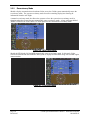
NOTE
All G1000 screen shots used in this document are current at the time of publication. Screen shots are
intended to provide visual reference only. All information depicted in screen shots, including software
file names, versions and part numbers, is subject to change and may not be up to date.
NOTE
The LRU serial numbers displayed on the screen are for convenience only and should be disregarded in
determining the LRU software revision. For compliance activities requiring LRU serial number
determination, the unit serial number used must be that on the physical LRU label, not the one displayed
on the SYSTEM STATUS page.
NOTE
All references to Diamond DA 40 aircraft made in this manual equally apply to Diamond DA 40 F
aircraft, unless otherwise noted.
NOTE
All references to GIA 63 LRUs made in this manual equally apply to GIA 63W LRUs unless otherwise
noted.
G1000 System Maintenance Manual – Diamond DA40/40F
190-00545-01
Page i
Revision G
TABLE OF CONTENTS
PARAGRAPH
PAGE
1 1.1 1.2 1.3 1.4 1.5 1.6 INTRODUCTION
1-1 CONTENT, SCOPE, PURPOSE .......................................................................................................... 1-1 ORGANIZATION ............................................................................................................................. 1-9 DEFINITIONS/ABBREVIATIONS .................................................................................................... 1-10 PUBLICATIONS ............................................................................................................................ 1-12 DISTRIBUTION ............................................................................................................................. 1-14 REQUIRED MATERIALS & EQUIPMENT ....................................................................................... 1-14 2 2.1 2.2 2.3 2.4 2.5 2.6 2.7 2.8 2.9 SYSTEM DESCRIPTION
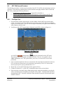
2-1 STC REQUIREMENTS OVERVIEW .................................................................................................. 2-1 EQUIPMENT DESCRIPTIONS ........................................................................................................... 2-2 G1000 OPTIONAL INTERFACES ..................................................................................................... 2-5 GFC 700 AFCS SYSTEM DESCRIPTION ........................................................................................ 2-7 ELECTRICAL POWER DISTRIBUTION ........................................................................................... 2-13 LIGHTNING STRIKE PROTECTION ................................................................................................ 2-16 SHIELD BLOCK GROUNDS ........................................................................................................... 2-17 SENSOR INSTALLATIONS ............................................................................................................. 2-17 BLOCK DIAGRAMS ...................................................................................................................... 2-17 3 3.2 3.3 3.4 3.5 G1000 CONTROL & OPERATION
3-1 G1000 OPERATION MODES ........................................................................................................... 3-3 G1000 CONFIGURATION MODE OVERVIEW.................................................................................. 3-5 G1000 / GFC 700 SOFTWARE INFORMATION.............................................................................. 3-14 G1000 SOFTWARE/CONFIGURATION PROCEDURE ...................................................................... 3-23 4 4.1 4.2 4.3 4.4 4.5 4.6 4.7 4.8 4.9 4.10 4.11 4.12 4.13 INSTRUCTIONS FOR CONTINUED AIRWORTHINESS
4-1 AIRWORTHINESS LIMITATIONS ..................................................................................................... 4-1 SERVICING INFORMATION ............................................................................................................. 4-2 MAINTENANCE INTERVALS ........................................................................................................... 4-4 VISUAL INSPECTION ...................................................................................................................... 4-8 ELECTRICAL BONDING TEST ....................................................................................................... 4-11 FUEL TANK PROBE RE-CALIBRATION ........................................................................................ 4-13 GRS 77 EARTH MAGNETIC FIELD UPDATES............................................................................... 4-21 GSA 81 GREASING PROCEDURE ................................................................................................. 4-21 FLAP POSITION DISCRETE INPUT CHECK .................................................................................... 4-22 SLIP CLUTCH TORQUE CHECK PROCEDURES .............................................................................. 4-24 PFD/MFD POWER INTERRUPT FUNCTION CHECKS .................................................................... 4-30 LIGHTNING PROTECTION FUSE REPLACEMENT .......................................................................... 4-35 COOLING FAN FUNCTION & FAN FAIL ANNUNCIATION TEST .................................................... 4-39 5 5.1 5.2 5.3 5.4 5.5 5.6 5.7 5.8 5.9 5.10 TROUBLESHOOTING
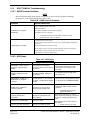
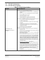
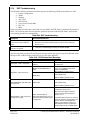
5-1 G1000 ALERTING SYSTEM ............................................................................................................ 5-2 SYSTEM ANNUNCIATIONS ............................................................................................................. 5-5 DA 40/DA 40 F SPECIFIC ALERTS .............................................................................................. 5-12 TAWS TROUBLESHOOTING ........................................................................................................ 5-14 GFC 700 AFCS TROUBLESHOOTING .......................................................................................... 5-15 BACKUP COMMUNICATIONS PATH CHECKS ............................................................................... 5-27 GDU 104X TROUBLESHOOTING ................................................................................................. 5-42 GDU 104X ALERTS .................................................................................................................... 5-43 GIA 63 TROUBLESHOOTING........................................................................................................ 5-50 GIA ALERT MESSAGES ............................................................................................................... 5-51 Page ii
Revision G
G1000 System Maintenance Manual – Diamond DA40/40F
190-00545-01
5.11 5.12 5.13 5.14 5.15 5.16 5.17 5.18 5.19 GEA TROUBLESHOOTING ........................................................................................................... 5-55 GTX TROUBLESHOOTING ........................................................................................................... 5-55 GRS 77/GMU 44 TROUBLESHOOTING ........................................................................................ 5-56 GDC 74A TROUBLESHOOTING ................................................................................................... 5-57 GDL 69A TROUBLESHOOTING.................................................................................................... 5-58 GDL 59 TROUBLESHOOTING ...................................................................................................... 5-59 GSR 56 TROUBLESHOOTING ....................................................................................................... 5-60 SYNTHETIC VISION AND PATHWAYS TROUBLESHOOTING ......................................................... 5-61 ESP TROUBLESHOOTING............................................................................................................. 5-62 6 6.1 6.2 6.3 6.4 6.5 6.6 6.7 6.8 6.9 6.10 6.11 6.12 6.13 6.14 6.15 6.16 6.17 6.18 G1000 EQUIPMENT REMOVAL & REPLACEMENT
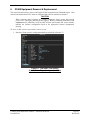
6-1 GDU 104X MFD & PFD............................................................................................................... 6-4 GMA 1347 AUDIO PANEL ............................................................................................................. 6-4 GIA 63 (W) INTEGRATED AVIONICS UNITS .................................................................................. 6-4 GEA 71 ENGINE/AIRFRAME UNIT ................................................................................................ 6-5 GTX 33 TRANSPONDER ................................................................................................................ 6-5 GTP 59 OAT PROBE ..................................................................................................................... 6-6 GRS 77 AHRS .............................................................................................................................. 6-6 GMU 44 MAGNETOMETER ........................................................................................................... 6-7 GDL 69A....................................................................................................................................... 6-7 GSA 81 SERVOS ............................................................................................................................ 6-7 GSM 85 & GSM 86 SERVO MOUNTS ............................................................................................ 6-8 CONFIGURATION MODULE REMOVAL & REPLACEMENT ............................................................. 6-8 GEA 71 BACKSHELL THERMOCOUPLE REMOVAL & REPLACEMENT ......................................... 6-11 GA35 GPS/WAAS ANTENNAS ................................................................................................... 6-12 GDL 59 DATALINK ..................................................................................................................... 6-12 GSR 56 SATELLITE RECEIVER .................................................................................................... 6-12 IRIDIUM ANTENNA (OPTIONAL) .................................................................................................. 6-13 WI-FI ANTENNA (OPTIONAL) ..................................................................................................... 6-13 7 7.1 7.2 7.3 7.4 7.5 7.6 7.7 7.8 7.9 7.10 7.11 G1000 EQUIPMENT CONFIGURATION & TESTING
7-1 GDU 104X MFD & PFD............................................................................................................... 7-3 GMA 1347 AUDIO PANEL ............................................................................................................. 7-7 GIA 63 INTEGRATED AVIONICS UNIT ......................................................................................... 7-10 GEA 71 ENGINE/AIRFRAME UNIT .............................................................................................. 7-16 GTX 33 TRANSPONDER .............................................................................................................. 7-19 GDC 74A AIR DATA COMPUTER ................................................................................................ 7-21 GRS 77 AHRS / GMU 44 MAGNETOMETER ............................................................................... 7-25 GDL 69 XM DATA LINK ............................................................................................................. 7-36 GDL 59 DATALINK ..................................................................................................................... 7-37 GSR 56 ........................................................................................................................................ 7-39 GSA 81 SERVO ............................................................................................................................ 7-42 8 8.1 8.2 8.3 8.4 SYSTEM RETURN TO SERVICE PROCEDURE
8-1 SOFTWARE VERIFICATION ............................................................................................................ 8-1 BACKUP PATH SYSTEM TESTING .................................................................................................. 8-2 GFC 700 GROUND CHECKOUT.................................................................................................... 8-10 MAINTENANCE RECORDS ........................................................................................................... 8-13 G1000 System Maintenance Manual – Diamond DA40/40F
190-00545-01
Page iii
Revision G
LIST OF ILLUSTRATIONS
FIGURE
PAGE
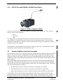
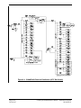
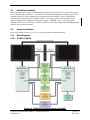
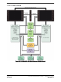
Figure 2-1. SVS/Pathways Feature ........................................................................................................... 2-6 Figure 2-2. AFCS System Block Diagram................................................................................................ 2-9 Figure 2-3. GSA 81 & GSM 85 or GSM 86 ........................................................................................... 2-11 Figure 2-4. G1000/DA40 Electrical Distribution (GFC 700 Aircraft).................................................... 2-14 Figure 2-5. G1000/DA40 Electrical Distribution (KAP140 Aircraft) .................................................... 2-15 Figure 2-6. G1000/KAP 140 Block Diagram (no WAAS) ..................................................................... 2-17 Figure 2-7. G1000/GFC 700 Block Diagram (WAAS shown) ............................................................... 2-18 Figure 3-1. GDU 104X Control Interface (GDU 1042 shown) ................................................................ 3-1 Figure 3-2. AFCS Controls (GDU 1044 shown) ...................................................................................... 3-1 Figure 3-3. GMA 1347 Controls ............................................................................................................... 3-2 Figure 3-4. G1000 Softkeys ...................................................................................................................... 3-3 Figure 3-5. Normal Mode ......................................................................................................................... 3-3 Figure 3-6. MFD Failure Mode................................................................................................................. 3-4 Figure 3-7. PFD Failure Mode .................................................................................................................. 3-4 Figure 3-8. SYSTEM UPLOAD FIELDS (SW v0321.19 or earlier) ....................................................... 3-5 Figure 3-9. SYSTEM UPLOAD FIELDS (SW v0321.22 or later) .......................................................... 3-5 Figure 3-10. SET>ACTV Diagram........................................................................................................... 3-7 Figure 3-11. Loss of Communication ....................................................................................................... 3-8 Figure 3-12. Configuration Status............................................................................................................. 3-8 Figure 3-13. Data Transmission Indicators ............................................................................................. 3-10 Figure 3-14. MFD Power Up Splash Screen System Software Version ................................................. 3-14 Figure 3-15. MFD AUX –System Status Page System Software Version.............................................. 3-14 Figure 3-16. Options Configuration Files System Upload Page ............................................................. 3-17 Figure 3-17. Calibration Files System Upload Page ............................................................................... 3-18 Figure 3-18. G1000 LRU Configuration File Storage ............................................................................ 3-21 Figure 3-19. GRS/GDC Configuration Settings Storage ........................................................................ 3-22 Figure 3-20. Software/Configuration Overview ..................................................................................... 3-23 Figure 3-21. Non-WAAS (GIA 63) System Status Page ........................................................................ 3-27 Figure 3-22. WAAS (GIA 63W) System Status Page ............................................................................ 3-28 Figure 3-23. System Upload Page........................................................................................................... 3-28 Figure 3-24. GIA Boot Block Upload Page ............................................................................................ 3-31 Figure 3-25. GIA Boot Block Upload Complete Page ........................................................................... 3-32 Figure 3-26. System Status Page (SW v0321.19 and earlier) ................................................................. 3-33 Figure 3-27. System Status Page (SW v0321.22 or later)....................................................................... 3-33 Figure 3-28. System ID Location............................................................................................................ 3-41 Figure 3-29. System Upload Page........................................................................................................... 3-43 Figure 3-30. DA40 Splash Screen for Non ESP Configurations ............................................................ 3-45 Figure 3-31. DA40 FP Splash Screen for Non ESP Configurations ....................................................... 3-45 Figure 3-32. DA40 Splash Screen for ESP Configurations .................................................................... 3-46 Figure 3-33. DA40 FP Splash Screen for ESP Configurations ............................................................... 3-46 Figure 4-1. Total Time In Service ............................................................................................................. 4-3 Figure 4-2 Fuel Calibration Page (Calibration Table) ............................................................................. 4-14 Figure 4-3 System Upload Page............................................................................................................... 4-15 Figure 4-4 Fuel Calibration Page ............................................................................................................. 4-17 Figure 4-5 Fuel Calibration Page (Empty Calibration) ............................................................................ 4-18 Figure 4-6 System Upload Page............................................................................................................... 4-18 Figure 4-7 Fuel Calibration Page (5 Gallon Calibration)......................................................................... 4-19 Figure 4-8 System Upload Page............................................................................................................... 4-20 Figure 4-9 Fuel Calibration Page (Calibration Complete) ....................................................................... 4-20 Figure 4-10. (SW v0321.19 or earlier) GIA I/O Page............................................................................. 4-22 Page iv
Revision G
G1000 System Maintenance Manual – Diamond DA40/40F
190-00545-01
Figure 4-11. (SW v0321.22 or later) GIA I/O Page................................................................................ 4-23 Figure 4-12, GFC Status Page................................................................................................................. 4-24 Figure 4-13. GDU TEST Page ................................................................................................................ 4-30 Figure 4-14. Backup Capacitor Test Selection ....................................................................................... 4-32 Figure 4-15. Upload Complete Window ................................................................................................. 4-33 Figure 4-16. BKUP CAPS Checkbox on GDU TEST Page ................................................................... 4-34 Figure 4-17. Aircraft Fuselage Fuse Locations ....................................................................................... 4-35 Figure 4-18. Instrument Panel Detail A .................................................................................................. 4-36 Figure 4-19. Instrument Panel Detail B .................................................................................................. 4-36 Figure 4-20. Remote Avionics Enclosure Detail C................................................................................. 4-37 Figure 4-21. Remote Avionics Enclosure Detail D ................................................................................ 4-38 Figure 5-1. AUX – System Status Page .................................................................................................... 5-1 Figure 5-2. Alerts & Annunciations .......................................................................................................... 5-2 Figure 5-3. WARNING Softkey Annunciation ........................................................................................ 5-3 Figure 5-4. CAUTION Softkey Annunciation .......................................................................................... 5-3 Figure 5-5. ADVISORY Softkey Annunciation ....................................................................................... 5-3 Figure 5-6. System Annunciations ............................................................................................................ 5-5 Figure 5-7. AFCS Annunciation Field .................................................................................................... 5-15 Figure 5-8, GFC Status Page................................................................................................................... 5-18 Figure 5-9. GMA 1347 Data Paths ......................................................................................................... 5-27 Figure 5-10. GEA 71 Data Paths ............................................................................................................ 5-28 Figure 5-11. GTX 33 Data Paths ............................................................................................................ 5-29 Figure 5-12. GDC 74A Data Paths ......................................................................................................... 5-30 Figure 5-13. GRS 77 Data Paths ............................................................................................................. 5-31 Figure 6-1. (SW v0321.19 or earlier) System Status Page (Configuration Mode) .................................. 6-1 Figure 6-2. (SW v0321.22 or later) System Status Page (Configuration Mode) ..................................... 6-2 Figure 6-3. Configuration Module Installation ......................................................................................... 6-9 Figure 6-4. GEA Backshell Thermocouple............................................................................................. 6-11 Figure 7-1. Non-WAAS (GIA 63) System Status Page ............................................................................ 7-2 Figure 7-2. WAAS (GIA 63W) System Status Page ................................................................................ 7-2 Figure 7-3. G1000 Normal Mode Check .................................................................................................. 7-5 Figure 7-4. G1000 Reversionary Mode Check ......................................................................................... 7-6 Figure 7-5. MFD TAWS Page .................................................................................................................. 7-6 Figure 7-6. Marker Beacon Symbology .................................................................................................... 7-9 Figure 7-7. SET>ACTV Softkey ............................................................................................................ 7-10 Figure 7-8. AUX – GPS STATUS Page (MFD) ..................................................................................... 7-12 Figure 7-9. Engine Instrument Pages ...................................................................................................... 7-17 Figure 7-10. Engine Instrument Sub Pages ............................................................................................. 7-18 Figure 7-11. GTX Configuration Page ................................................................................................... 7-20 Figure 7-12. EASA Airspeed Tape ......................................................................................................... 7-23 Figure 7-13. GRS/GMU Calibration Page .............................................................................................. 7-28 Figure 7-14. GRS/GMU Calibration Page .............................................................................................. 7-30 Figure 7-15. GRS/GMU Calibration Page .............................................................................................. 7-32 Figure 7-16. Magnetometer Interference Test Page ................................................................................ 7-33 Figure 7-17. Normal Mode AHRS Check .............................................................................................. 7-35 Figure 7-18. Reversionary Mode AHRS Information............................................................................. 7-35 Figure 7-19. GSR 56 Configuration Page for Combination Option ....................................................... 7-38 Figure 7-20. Good Iridium Signal Strength ............................................................................................ 7-38 Figure 7-21. No Iridium Signal Strength ................................................................................................ 7-39 Figure 7-22. GSR 56 Configuration Page for Combination Option ....................................................... 7-40 Figure 7-23. GSR 56 Configuration Page for Standalone Option .......................................................... 7-40 Figure 7-24. Good Iridium Signal Strength ............................................................................................ 7-41 Figure 7-25. No Iridium Signal Strength ................................................................................................ 7-41 G1000 System Maintenance Manual – Diamond DA40/40F
190-00545-01
Page v
Revision G
Figure 8-1.
Figure 8-2.
Figure 8-3.
Figure 8-4.
PFD RS-232/ARINC 429 Configuration Page ....................................................................... 8-7 GIA1 RS-232/ARING 429 Configuration Page ..................................................................... 8-8 GIA1 RS-485 Configuration Page ......................................................................................... 8-9 Pre-Flight Test ...................................................................................................................... 8-10 Page vi
Revision G
G1000 System Maintenance Manual – Diamond DA40/40F
190-00545-01
LIST OF TABLES
TABLE
PAGE
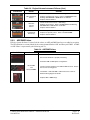
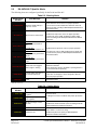
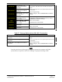
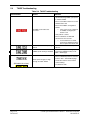
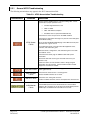
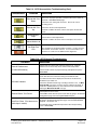
Table 1-1. MDL Configurations Summary ............................................................................................... 1-2 Table 1-2. Required Documents ............................................................................................................. 1-12 Table 1-3. Previously Approved Type Design........................................................................................ 1-13 Table 1-4. Reference Publications .......................................................................................................... 1-13 Table 1-5. Loader Card to Configuration Relationship Summary .......................................................... 1-15 Table 3-1. Data Transmission Indicators .................................................................................................. 3-9 Table 3-2. Page Navigation SW v0321.19 or earlier .............................................................................. 3-11 Table 3-3. Page Navigation SW v0321.22 .............................................................................................. 3-12 Table 3-4. Page Navigation SW v0321.23 .............................................................................................. 3-13 Table 3-5. LRU to Configuration File Relationship Summary ............................................................... 3-19 Table 4-1. Maintenance Intervals.............................................................................................................. 4-4 Table 4-2. Visual Inspection Procedure .................................................................................................... 4-8 Table 4-3. GSM 86 Measured Torque .................................................................................................... 4-28 Table 4-4. Power Interrupt Category A (200mS) Mod Status ................................................................ 4-30 Table 4-5. Power Interrupt Category A (200mS) Mod Status ................................................................ 4-31 Table 4-6. Lightning Protection Fuse Part Numbers .............................................................................. 4-35 Table 5-1. Aural and Audio Alerts............................................................................................................ 5-4 Table 5-2. System Failure Troubleshooting .............................................................................................. 5-6 Table 5-3. Engine Airframe Instrument Failures .................................................................................... 5-10 Table 5-4. ADF/DME Failure ................................................................................................................. 5-11 Table 5-5. Warning Alerts ...................................................................................................................... 5-12 Table 5-6. Caution Alerts ........................................................................................................................ 5-12 Table 5-7. Message Advisory Alerts (SW v0321.22 and earlier) ........................................................... 5-13 Table 5-8. TAWS Troubleshooting ........................................................................................................ 5-14 Table 5-9. AFCS Annunciation Troubleshooting ................................................................................... 5-16 Table 5-10. AFCS General Troubleshooting .......................................................................................... 5-17 Table 5-11. PFT Faults (Monitor Processor) .......................................................................................... 5-24 Table 5-12. Normal Mode Faults (Monitor Processor) ........................................................................... 5-24 Table 5-13. PFT Faults (Control Processor) ........................................................................................... 5-25 Table 5-14. Normal Mode Faults (Control Processor)............................................................................ 5-25 Table 5-15. Data Path Failure Troubleshooting ...................................................................................... 5-32 Table 5-16. PFD1 ARINC 429 ............................................................................................................... 5-33 Table 5-17. MFD1 ARINC 429 .............................................................................................................. 5-34 Table 5-18. GIA1 RS-232 ....................................................................................................................... 5-35 Table 5-19. GIA1 ARINC 429................................................................................................................ 5-37 Table 5-20. GIA2 RS-232 ....................................................................................................................... 5-38 Table 5-21. GIA2 ARINC 429................................................................................................................ 5-39 Table 5-22. GIA1 RS-485 ....................................................................................................................... 5-40 Table 5-23. GIA2 RS-485 ....................................................................................................................... 5-41 Table 5-24. GDU 104X Common Problems ........................................................................................... 5-42 Table 5-25. GDU 104X Software/Configuration Alerts ......................................................................... 5-43 Table 5-26. Database Alerts .................................................................................................................... 5-44 Table 5-27. Cooling Alerts ..................................................................................................................... 5-45 Table 5-28. Datacard Alerts .................................................................................................................... 5-46 Table 5-29. Key Alerts ............................................................................................................................ 5-46 Table 5-30. Miscellaneous Alerts ........................................................................................................... 5-47 Table 5-31. GMA Common Problems .................................................................................................... 5-49 Table 5-32. GMA Alerts ......................................................................................................................... 5-49 Table 5-33. COM Troubleshooting ......................................................................................................... 5-50 G1000 System Maintenance Manual – Diamond DA40/40F
190-00545-01
Page vii
Revision G
Table 5-34. NAV Troubleshooting ......................................................................................................... 5-50 Table 5-35. GS Troubleshooting............................................................................................................. 5-50 Table 5-36. GPS Troubleshooting .......................................................................................................... 5-50 Table 5-37. COM Alerts ......................................................................................................................... 5-51 Table 5-38. NAV AlertsFailure Message ............................................................................................... 5-52 Table 5-39. Glideslope Alerts ................................................................................................................. 5-53 Table 5-40. GPS Alerts ........................................................................................................................... 5-53 Table 5-41. GIA Cooling Alerts ............................................................................................................. 5-54 Table 5-42. GIA Configuration Alerts .................................................................................................... 5-54 Table 5-43. GEA Common Problems ..................................................................................................... 5-55 Table 5-44. GEA Alerts .......................................................................................................................... 5-55 Table 5-45. GTX Alerts .......................................................................................................................... 5-55 Table 5-46. AHRS Common Problems................................................................................................... 5-56 Table 5-47. GRS Alerts........................................................................................................................... 5-56 Table 5-48. GMU Alerts ......................................................................................................................... 5-57 Table 5-49. Air Data Common Problems ............................................................................................... 5-57 Table 5-50. GDC Alerts .......................................................................................................................... 5-57 Table 5-51. GDL 69A Common Problems ............................................................................................. 5-58 Table 5-52. GDL 69A Alerts .................................................................................................................. 5-59 Table 5-53. GDL 59 Troubleshooting..................................................................................................... 5-59 Table 5-54. GDL 59 Alerts ..................................................................................................................... 5-59 Table 5-55. GSR 56 Troubleshooting ..................................................................................................... 5-60 Table 5-56. GSR 56 Alerts...................................................................................................................... 5-60 Table 5-57. SVS Troubleshooting ........................................................................................................... 5-61 Table 5-58. SVS-Related Alert Messages............................................................................................... 5-61 Table 5-59. ESP Troubleshooting ............................................................................................................ 5-62 Table 5-60. ESP-Related Alert Messages ............................................................................................... 5-62 Table 6-1. Equipment Removal and Replacement Software Check ......................................................... 6-2 Table 6-2. Configuration Module Kit – 011-00979-00 ............................................................................. 6-9 Table 6-3. Thermocouple Kit (011-00981-00) ....................................................................................... 6-11 Table 7-1: Engine/Airframe Instrument Checks ..................................................................................... 7-18 Table 7-2. Airspeed Test ......................................................................................................................... 7-23 Table 7-3. EASA Airspeed Tape Test .................................................................................................... 7-23 Table 7-4. Vertical Speed Test Tolerances ............................................................................................. 7-24 Table 7-5. GRS/GMU Calibration Requirement Matrix......................................................................... 7-26 Table 7-6. Magnetometer Interference Test Sequence (Example).......................................................... 7-33 Table 8-1. Return To Service Software Check ......................................................................................... 8-1 Table 8-2. GPS Failure Test...................................................................................................................... 8-3 Table 8-3. GIA Failure Test ...................................................................................................................... 8-4 Table 8-4. Display Failure Test................................................................................................................. 8-6 Page viii
Revision G
G1000 System Maintenance Manual – Diamond DA40/40F
190-00545-01
1
1.1
INTRODUCTION
Content, Scope, Purpose
This document provides Instructions for Continued Airworthiness (ICA) for the Garmin G1000 integrated
avionics and GFC700 Automatic Flight Control System (AFCS) as installed in the Diamond Model
DA 40 and DA 40 F. This document satisfies the requirements for continued airworthiness as defined by
14 CFR Part 23.1529 and Appendix G. Information in this document is required to maintain the
continued airworthiness of the G1000 and GFC700.
1.1.1
Applicability
This document applies to all Diamond Aircraft Industries, Inc., Model DA 40 and DA 40 F aircraft
equipped with the G1000 and optional GFC700 AFCS system under this STC.
Modification of an aircraft by this Supplemental Type Certificate (STC) obligates the aircraft operator to
include the maintenance information provided by this document in the operator’s Aircraft Maintenance
Manual and the operator’s Aircraft Scheduled Maintenance Program.
This System Maintenance manual and the contained Instructions for Continued Airworthiness supersedes
all previous system maintenance manuals and ICAs, including the following Garmin documents:
• 190-00303-03
• 190-00492-01
• 190-00492-03
• 190-00545-00
NOTE
Differences in software versions that affect the maintenance manual content will be indicated within the
procedures as needed. If no indication of software version is provided for the procedure or step then it is
understood to apply to all software versions.
G1000 System Maintenance Manual – Diamond DA40/40F
190-00545-01
Page 1-1
Revision G
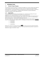
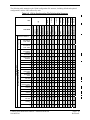
1.1.2
Identifying an MDL Configuration
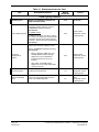
There are six approved configurations within this STC, each defined as a subset of the Master Drawing
List (MDL). Each configuration differs in both hardware and software installation requirements.
Refer to the MDL, Garmin document 005-00400-01 for each configuration type design definition.
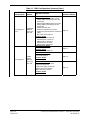
Table 1-1. MDL Configurations Summary
MDL
Configuration
-1 Configuration
Page 1-2
Revision G
Aircraft
System
Upgrades Available
G1000 &
GFC 700
with WAAS
Major Functions Added
• G1000 & GFC 700 AFCS
• WAAS
• Coupled baro-VNAV
• GDU Charts
• Misc. GDU v8.02 features
Hardware Added
GDU 1044 MFD Optional
GIA 63W Integrated Avionics (qty 2)
GA35 GPS/WAAS antennas (qty 2)
Major Functions Added
• Misc. GDU v8.20 features
Hardware Added
GIA 63W P/N 011-01105-01
GDC 74A P/N 011-00882-10
Major Functions Added
• Misc. GDU v9.01 features
Hardware Added
None
Major Functions Added
• Misc. GDU v9.01 features
(Non WAAS Support)
Hardware Added
None
Major Functions Added
• Import Flt Plans from SD Card
• Temporary Waypoints
• Flight Data Logging to SD Card
• GDL69 Aviator Pro features
• Misc. GDU v9.15 features
Hardware Added
None
G1000 System
Software Version
0369.13
0321.17
0321.18
0321.19
0321.22
G1000 System Maintenance Manual – Diamond DA40/40F
190-00545-01
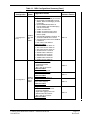
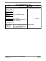
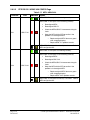
Table 1-1. MDL Configurations Summary (Cont.)
MDL
Configuration
-1 Configuration
(Cont)
-2 Configuration
Aircraft
System
G1000 &
GFC 700
with
WAAS
G1000 &
GFC 700
without
WAAS
Upgrades Available
Major Functions Added
• Optional Electronic Stability & Protection
• Optional GDL 59 /GSR 56B to include
WWWx, SMS Text Messaging and TEL
functionality
• Optional GSR 56B standalone to
include WWWx, SMS Text Messaging
and TEL functionality
• Addition of Profile View
• Addition of Synthetic Vision (SVS)
• Addition of Enhanced Search and
Rescue (SAR)
• Add optional installation of GSA 81 -20
servos and GSM 86 servo mounts.
• Automated Slip Clutch Test for GSM 86
Installations
• Misc. GDU v12.05 features
Hardware Added
• GDU 1040 P/N 011-00972-10
• GDU 1042 P/N 011-01080-10
• GDU 1044 P/N 011-01078-10
• GIA63W P/N 011-01105-20
• GMU44 P/N 011-00870-10
• GDL59 P/N 011-01746-00
• GSR56 P/N 011-02268-00
• GSM86 P/N 011-01904-03
• GSA81 P/N 011-00878-20
Major Functions Added
• G1000 & GFC 700 AFCS
• Coupled baro-VNAV
• GDU Charts
• Misc. GDU v8.02 features
Hardware Added
GDU 1044 MFD Optional
Major Functions Added
• Misc. GDU v8.20 features
Hardware Added
GDC 74A P/N 011-00882-10
Major Functions Added
• Misc. GDU v9.01 features
(Non WAAS Support)
Hardware Added
None
Major Functions Added
• Import Flt Plans from SD Card
• Temporary Waypoints
• Flight Data Logging to SD Card
• GDL69 Aviator Pro features
• Misc. GDU v9.15 features
Hardware Added
None
G1000 System Maintenance Manual – Diamond DA40/40F
190-00545-01
G1000 System
Software Version
0321.23
0369.13
0321.17
0321.19
0321.22
Page 1-3
Revision G
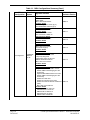
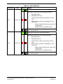
Table 1-1. MDL Configurations Summary (Cont.)
MDL
Configuration
Aircraft
System
Upgrades Available
Major Functions Added
• WAAS
• GDU Charts
• Misc. GDU v8.02 features
Hardware Added
GIA 63W Integrated Avionics (qty 2)
GA35 GPS/WAAS antennas (qty 2)
Major Functions Added
• Misc. GDU v8.20 features
Hardware Added
GIA 63W P/N 011-01105-01
GDC 74A P/N 011-00882-10
-3 Configuration
Page 1-4
Revision G
G1000 with
WAAS &
No AP
G1000 System
Software Version
0369.13
0321.17
Major Functions Added
• Misc. GDU v9.01 features
Hardware Added
None
0321.18
Major Functions Added
• Misc. GDU v9.01 features
(Non WAAS Support)
Hardware Added
None
0321.19
Major Functions Added
• Import Flt Plans from SD Card
• Temporary Waypoints
• Flight Data Logging to SD Card
• GDL69 Aviator Pro features
• Misc. GDU v9.15 features
Hardware Added
None
0321.22
Major Functions Added
• Optional GDL 59 /GSR 56B to include
WWWx, SMS Text Messaging and TEL
functionality
• Optional GSR 56B standalone to include
WWWx, SMS Text Messaging and TEL
functionality
• Addition of Profile View
• Addition of Synthetic Vision (SVS)
• Addition of Enhanced Search and Rescue
(SAR)
• Misc. GDU v12.05 features
Hardware Added
• GDU 1040 P/N 011-00972-10
• GIA63W P/N 011-01105-20
• GMU44 P/N 011-00870-10
• GDL59 P/N 011-01746-00
• GSR56 P/N 011-02268-00
0321.23
G1000 System Maintenance Manual – Diamond DA40/40F
190-00545-01
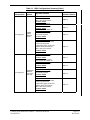
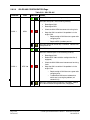
Table 1-1. MDL Configurations Summary (Cont.)
MDL
Configuration
-4 Configuration
Aircraft
System
G1000
without
WAAS &
No AP
Upgrades Available
Major Functions Added
• GDU Charts
• Misc. GDU v8.02 features
Hardware Added
GDU 1044 MFD Optional
Major Functions Added
• Misc. GDU v8.20 features
Hardware Added
GDC 74A P/N 011-00882-10
Major Functions Added
• Misc. GDU v9.01 features
(Non WAAS Support)
Hardware Added
None
Major Functions Added
• Import Flt Plans from SD Card
• Temporary Waypoints
• Flight Data Logging to SD Card
• GDL69 Aviator Pro features
• Misc. GDU v9.15 features
Hardware Added
None
Major Functions Added
• Misc. GDU v8.20 features
Hardware Added
GIA 63W P/N 011-01105-01
GDC 74A P/N 011-00882-10
Major Functions Added
• Misc. GDU v9.01 features
Hardware Added
None
-5 Configuration
G1000 with
WAAS &
Honeywell
KAP 140
G1000 System
Software Version
0369.13
0321.17
0321.19
0321.22
0321.17
0321.18
Major Functions Added
• Misc. GDU v9.01 features
(Non WAAS Support)
Hardware Added
None
0321.19
Major Functions Added
• Import Flt Plans from SD Card
• Temporary Waypoints
• Flight Data Logging to SD Card
• GDL69 Aviator Pro features
• Misc. GDU v9.15 features
Hardware Added
None
0321.22
G1000 System Maintenance Manual – Diamond DA40/40F
190-00545-01
Page 1-5
Revision G
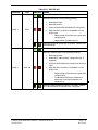
Table 1-1. MDL Configurations Summary (Cont.)
MDL
Configuration
-5 Configuration
(Cont)
-6 Configuration
Page 1-6
Revision G
Aircraft
System
G1000 with
WAAS &
Honeywell
KAP 140
G1000
without
WAAS &
Honeywell
KAP 140
Upgrades Available
Major Functions Added
• Optional GDL 59 /GSR 56B to include
WWWx, SMS Text Messaging and TEL
functionality
• Optional GSR 56B standalone to include
WWWx, SMS Text Mesaging and TEL
functionality
• Addition of Profile View
• Addition of Synthetic Vision (SVS)
• Addition of Enhanced Search and Rescue
(SAR)
• Misc. GDU v12.05 features
Hardware Added
• GDU 1040 P/N 011-00972-10
• GIA63W P/N 011-01105-20
• GMU44 P/N 011-00870-10
• GDL59 P/N 011-01746-00
• GSR56 P/N 011-02268-00
Major Functions Added
• Misc. GDU v8.20 features
Hardware Added
GDC 74A P/N 011-00882-10
Major Functions Added
• Misc. GDU v9.01 features
(Non WAAS Support)
Hardware Added
None
Major Functions Added
• Import Flt Plans from SD Card
• Temporary Waypoints
• Flight Data Logging to SD Card
• GDL69 Aviator Pro features
• Misc. GDU v9.15 features
Hardware Added
None
G1000 System
Software Version
0321.23
0321.17
0321.19
0321.22
G1000 System Maintenance Manual – Diamond DA40/40F
190-00545-01
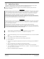
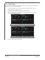
IMPORTANT!
If the technician is unsure of the G1000 MDL configuration, perform the following
steps:
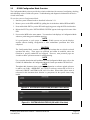
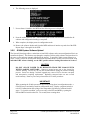
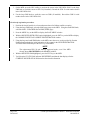
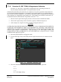
Check System Software Version
1. Power on the G1000 system by turning on the BAT master switch, then the AVIONICS MASTER
switch.
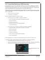
2. On the MFD power-up page, the G1000 system software version is displayed in the upper right corner
in the following format:
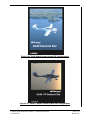
Diamond DA40 System XXXX.XX
-orDiamond DA40F System XXXX.XX
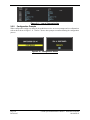
The system software version is also displayed at the AUX – SYSTEM STATUS page in the upper
right corner.
3. This system software version is the primary identifier of which G1000/GFC700 configuration is
installed. Refer to Table 1-1 for approved G1000 system software versions.
NOTE
The approved G1000 system software versions for this STC are listed in Table 1-1. If the
system software version differs from that shown in Table 1-1, investigate further to
determine which G1000 configuration is installed. Refer to the appropriate
G1000/GFC700 System Maintenance manual (see list of superseded manuals which may
apply in Section 1.1.1).
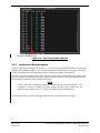
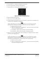
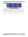
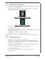
Check for GFC 700 AFCS Installation
To verify whether the GFC 700 AFCS is installed, do the following:
1. Check the G1000 MFD for dedicated AFCS mode control keys on the left side of the display (see
Figure 3-2).
2. Check the aircraft throttle lever for installation of a ‘Go Around’ (GA) button.
3. If the aircraft has these features installed, it is equipped with the Garmin GFC 700 autopilot.
4. The aircraft is either a -1 or a -2 MDL Configuration.
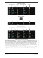
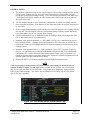
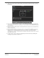
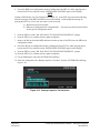
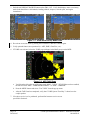
Check for WAAS Installation
To verify whether WAAS is installed, do the following:
1. On the MFD, go to the AUX – GPS STATUS page.
2. Check to see whether a softkey labeled SBAS is displayed. The SBAS softkey only appears if the
G1000 is equipped with GIA 63Ws.
3. If the SBAS softkey is present, the aircraft is a -1, -3, or a -5 MDL Configuration.
G1000 System Maintenance Manual – Diamond DA40/40F
190-00545-01
Page 1-7
Revision G
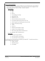
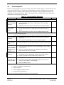
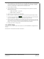
Check for Optional Installations
Identify all installation options currently installed on the aircraft which interface to the G1000 and
check each that applies in the following list. These options may need to be re-configured if a new
system software version is loaded or an LRU is removed or replaced.
DA40 / DA40 F:
ADF
DME
GDL 69
Extended Range Fuel Tanks
Standard GFC 700
Enhanced GFC 700
Electronic Stability and Protection (ESP)
No Autopilot Installed (No KAP140 or GFC 700)
EASA Airspeed Tape (EASA Registered Aircraft Only)
Display of Fuel Pressure Gauge
TAWS
ChartView
Enhanced Search and Rescue (SAR)
Synthetic Vision and Pathway (SVS)
GDL 59 Data Link & GSR 56 Satellite Receiver
Standalone GSR 56 Satellite Receiver
DA40 F Only:
Fuel Pressure Sensor Installed
One CHT and EGT sensor installed
Four CHT and EGT sensors installed
The following are provisional options not certified by any Garmin STC. To enable these interfaces, a
separate installation approval is required.
Page 1-8
Revision G
Avidyne TAS 600
WX500 Stormscope
CO Guardian
G1000 System Maintenance Manual – Diamond DA40/40F
190-00545-01
1.2
Organization
The following outline briefly describes the organization of this manual:
Section 2: System Description
Provides a complete description of the type design change associated with installing the G1000
integrated cockpit system in the Diamond DA 40. An overview of the G1000 and GFC 700 system
interface is also provided.
Section 3: G1000 Control & Operation
Presents basic control and operation information specifically tailored to maintenance practices. Basic
G1000 Configuration Mode operation is also described.
Section 4: G1000 Instructions for Continued Airworthiness
FAA-Approved Instructions for Continued Airworthiness provides airworthiness limitations and
scheduled maintenance requirements for the G1000 and GFC 700 systems.
Section 5: Troubleshooting
Provides troubleshooting information to aid in diagnosing and resolving potential problems with the
G1000 and GFC 700 systems.
Section 6: G1000 Equipment Removal & Replacement
Gives instructions for the removal and replacement of G1000 and GFC700 equipment.
Section 7: G1000 Equipment Configuration & Testing
Gives instructions for loading software, configuring, and testing of G1000 equipment.
Section 8: System Return to Service Procedure
Specifies return-to-service procedures to be performed upon completion of maintenance of the G1000
system.
G1000 System Maintenance Manual – Diamond DA40/40F
190-00545-01
Page 1-9
Revision G
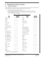
1.3
Definitions/Abbreviations
The following are some common acronyms & definitions found throughout this manual:
ADI:
Attitude Display Indicator
ADF:
Automatic Direction Finder
AFCS:
Automatic Flight Control System
AFMS: Airplane Flight Manual Supplement
AHRS: Attitude Heading Reference System
AMM:
Airplane Maintenance Manual
CDI:
Course Deviation Indicator
CDU:
Control Display Unit
CFR:
Code of Federal Regulations
DME:
Distance Measuring Equipment
EAU:
Engine/Airframe Unit
EIS:
Engine Instrumentation Systems
ESP:
Electronic Stability and Protection
GA
Go Around
GDC
Garmin Air Data Computer
GDL:
Garmin Data Link
GDU:
Garmin Display Unit
GEA:
Garmin Engine Airframe Unit
GFDS:
Garmin Flight Data Service
GIA:
Garmin Integrated Avionics
GMA:
Garmin Marker Beacon & Audio Panel Unit
GMU:
Garmin Magnetometer Unit
GPS:
Global Positioning System
GRS:
Garmin Reference System
GS:
Glideslope
GSA:
Garmin Servo Actuator
GSM:
Garmin Servo Mount
GSR:
Garmin Satellite Radio
GTX:
Garmin Transponder
HIRF:
High Intensity Radiated Fields
HSDB: High-Speed Data Bus (Ethernet)
HSI:
Horizontal Situation Indicator
IAU:
Integrated Avionics Unit
ICA:
Instructions for Continued Airworthiness
ICS:
Inter-Com System
ILS:
Instrument Landing System
LOC:
Localizer
Page 1-10
Revision G
G1000 System Maintenance Manual – Diamond DA40/40F
190-00545-01
LPV:
Localizer Precision with Vertical Guidance approach
LRU:
Line Replaceable Unit
MET:
Manual Electric Trim
MFD:
Multi-Function Flight Display
OAT:
Outside Air Temperature
OBS:
Omni-Bearing Selector
PFD:
Primary Flight Display
SAR
Search and Rescue
STC:
Supplemental Type Certificate
SVS
Synthetic Vision System
SW:
Software
TC:
Type Certificate
TSO:
Technical Standard Order
TVS:
Transient Voltage Suppressor
WAAS: Wide Area Augmentation System
VHF:
Very High Frequency
VOR:
Very High Frequency Omni-directional Range
1.3.1
Units of Measure
Unless otherwise stated, all units of measure are English units.
G1000 System Maintenance Manual – Diamond DA40/40F
190-00545-01
Page 1-11
Revision G
1.4
Publications
The following documents are required by this maintenance manual to perform maintenance:
Table 1-2. Required Documents
Part Number
Document
005-00400-01
STC Master Drawing List
005-00400-08
General Arrangement, G1000/KAP140, WAAS, Diamond DA40/40F
(-5 MDL Configuration)
005-00400-09
General Arrangement, G1000/KAP140, no WAAS, Diamond DA40/40F
(-6 MDL Configuration)
005-00400-10
General Arrangement, G1000/GFC700, WAAS, Diamond DA40/40F
(-1 MDL Configuration)
005-00400-11
General Arrangement, G1000/GFC700, no WAAS, Diamond DA40/40F
(-2 MDL Configuration)
005-00400-15
General Arrangement, G1000 Only, WAAS, Diamond DA40/40F
(-3 MDL Configuration)
005-00400-16
General Arrangement, G1000 Only, no WAAS, Diamond DA40/40F
(-4 MDL Configuration)
005-00400-12
Resistor Installation Drawing, G1000, WAAS, Diamond DA40/40F
(-1 & -3 MDL Configurations)
005-00400-13
Resistor Wiring Diagram, G1000, WAAS, Diamond DA40/40F
(-1 & -3 MDL Configurations)
005-00400-55
Optional Dual Audio Path Wiring For TAWS Installations in Diamond DA40 /
DA40F
DA4-9231-60-01
OR
DA4-9231-60-05
6.02.01
Diamond Wiring Diagram
(Diamond Part Number, -05 applies to GFC700 aircraft)
Diamond DA 40 Airplane Maintenance Manual (Diamond Part Number)
005-00400-92
Instl,Pitch Servo,GFC700 with GSM 86, Diamond DA40/40F
005-00400-93
Instl,Pitch Trim Servo,GFC700 with GSM 86, Diamond DA40/40F
005-00400-94
Instl,Roll Servo,GFC700 with GSM 86, Diamond DA40/40F
005-00464-10
Installation Modification, G1000/GFC700, WAAS, Diamond DA40/40F
005-00464-15
Installation Modification, G1000, WAAS, No Autopilot, Diamond DA40/40F
005-00464-00
Installation Modification, G1000/KAP140, WAAS, Diamond DA40/40F
005-00464-07
Antenna Install, GDL59/GSR56, DA40/40F
005-00464-08
GDL59/GSR56 Install, DA40/40F
005-00464-06
Wiring Diagram,GDL59/GSR56 in DA40/40F
005-00464-12
Wiring Diagram, GTX 33 Relocation, Diamond DA40 / DA 40 F
005-00464-13
Wiring Routing, GTX 33 Relocation, Diamond DA40 / DA 40 F
190-00355-04
GDL 69 Series XM Satellite Radio Activation Instructions
Page 1-12
Revision G
G1000 System Maintenance Manual – Diamond DA40/40F
190-00545-01
The following design drawings are carried over from the prerequisite previously approved STCs for
continued airworthiness purposes.
IMPORTANT!
Previous STC General Arrangement drawings, Required Equipment Lists, and
hardware/software equipment lists are obsolete and are now superseded by the new
General Arrangement drawings provided in Table 1-2. The following type design data
still applies to previously installed equipment.
Table 1-3. Previously Approved Type Design
Part Number
Document
STC#
005-00304-00
G1000 Install, Diamond DA40/40F
005-00336-17
Pitch Servo Installation, GFC700 AFCS, Diamond DA40/40F
005-00336-18
Roll Servo Installation, GFC700 AFCS, Diamond DA40/40F
005-00336-19
Pitch Trim Servo Installation, GFC700 AFCS, Diamond DA40/40F
SA01254WI-D
SA01389WI
The following publications are recommended to be available during maintenance activities.
Table 1-4. Reference Publications
Part Number
Document
005-00304-00
G1000 Install, Diamond DA40/40F
190-00492-08
Airplane Flight Manual Supplement: G1000 Synthetic Vision And Pathways Option
190-00492-09
Airplane Flight Manual Supplement: G1000 Electronic Stability and Protection (ESP)
Option for the Diamond DA40/DA40F
190-00492-10
Airplane Flight Manual Supplement: G1000 Integrated Avionics System with GFC 700
Automatic Flight Control System – Diamond Model DA40 & DA40F
190-00492-11
Airplane Flight Manual Supplement: G1000 Integrated Avionics System – Diamond
Model DA40 & DA40F
190-00492-12
Airplane Flight Manual Supplement: G1000 Integrated Avionics System – Diamond
Model DA40 & DA40F
190-00324-07
190-00324-08
190-00324-09
190-00324-10
190-00324-11
G1000/GFC700 DA 40 Cockpit Reference Guide*
190-00355-04
GDL 69/69A XM Satellite Radio Activation Instructions
190-00303-72
GSA8X/GSM85(A) Installation Manual
*See AFMS for correct CRG P/N required.
G1000 System Maintenance Manual – Diamond DA40/40F
190-00545-01
Page 1-13
Revision G
1.5
Distribution
This document is required for maintaining the continued airworthiness of aircraft equipped with this STC.
Revisions to this document will be made by Garmin and will be distributed by Garmin per standard
documentation revision procedures.
For the latest revision to this document, check Garmin’s web site at: www.garmin.com/ and click on
‘Dealer Resource Center’.
NOTE
Only Garmin-authorized dealers and service centers are given access to the Dealer
portion of the Web Site. If you do not have a Dealer Password, contact Garmin directly
to obtain the latest revision of this document.
1.6
Required Materials & Equipment
The following test equipment is required to conduct and complete all post installation checkout
procedures in this section (All test equipment should have current calibration records):
A ground power unit capable of supplying 28 Vdc power to the aircraft systems and avionics.
Outdoor line-of-site to GPS satellite signals or GPS indoor repeater.
Outdoor line-of-site to Iridium satellite signal.
Headset/Microphone.
A VHF NAV/COM Test Set
Air Data Test Set
L-Band Multi-Function Test Set
The following materials are defined on the applicable General Arrangement Drawing (see STC MDL):
G1000/DA40 Software Image
SD Card,GDU10XX BB Ldr,v2.03 (May be required. Refer to Section 3.5.3)
SD Card,G1000,GIA6X BBL 4.01(May be required. Refer to Section 3.5.7)
SD Card,GDU10xx Supp SVS, (TRN/OBS/APT DB/SUPP/SAFE TAXI)*
SD Card,GDU10xx TAWS Unlock (Optional)
SD Card,GDU10XX,Chart Unlock, Light AC (Optional)
SD Card, GDU1XXX Enhanced AFCS Unlock (Optional)
SD Card, G1000, Enhanced SAR Unlock (Optional)
SD Card,GDU10xx SVS Unlock,1 PFD (Optional)
*Terrain database cards are required by this STC. However, the newer updated cards which provide
SafeTaxi and Chart capability are an optional upgrade. If these newer cards are not installed, the existing
installed cards must still be used. Reference the applicable General Arrangement Drawing (see STC
MDL). See the applicable General Arrangement Drawing for each configuration in Master Drawing List,
005-00400-01 for additional details.
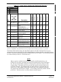
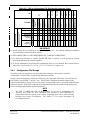
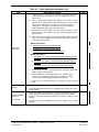
Table 1-5 lists the loader cards used in this upgrade and is derived from the appropriate General
Arrangement drawing for each configuration listed on MDL 005-00400-01. The appropriate General
Arrangement drawing should be followed if any differences exist.
Page 1-14
Revision G
G1000 System Maintenance Manual – Diamond DA40/40F
190-00545-01
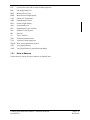
Table 1-5. Loader Card to Configuration Relationship Summary
010-00369-XX
006-B0321-XX
2 ea
010-00330-43
1 ea
010-00330-51
1 ea
010-00330-53
1 ea
1 ea
010-00330-02
006-B0874-00
010-00533-00
006-B0538-00
1 ea
010-00330-5B
1 ea
010-00330-59
1 ea
010-00330-54
SD Card,G1000,DA40
Ldr
SD Card,GDU10xx Supp
SVS
(TRN/OBS/APT
DB/SUPP/SAFE TAXI)
SD Card,GDU10xx
TAWS Unlock
SD Card,GDU10XX,Chart
Unlock, Light AC
SD Card,GDU10XX BB
Ldr,v2.03
SD Card,G1000,GIA6X
BBL 4.01
SD Card, GDU1XXX
Enhanced AFCS Unlock
SD Card, G1000,
Enhanced SAR Unlock
SD Card,GDU10xx SVS
Unlock,1 PFD
Config -6
1 ea
Description
Config -5
(Where Applicable)
Config -4
Qty
Config -3
010 - P/N
and
006 - P/N
Config -2
Legend
Required
Optional
See Note 1
See Note 2
Not Applicable
Config -1
R
O
*
†
NA
R
R
R
R
R
R
R
R
R
R
R
R
O
O
O
O
O
O
O
O
O
O
O
O
*
*
*
*
*
*
†
†
†
†
†
†
O
NA
NA
NA
NA
NA
O
O
O
O
O
O
O
O
O
O
O
O
(*) Note 1 - REQUIRED - Only if determined necessary to update GDU 104X boot block per section 3.5.3 procedures.
(†) Note 2 – REQUIRED - Only if determined necessary to update GIA 63 boot block per section 3.5.7 procedures.
The G1000/ DA40 Software Image file, Boot Block update for the GDU 104X and GIA 63 may be
electronically sourced via the listed 006- P/N. through Garmin to facilitate building a boot block software
SD Card. If desired, technician may purchase the Boot Block cards as a higher – level assembly produced
by Garmin, defined per the 010 – P/Ns shown above.
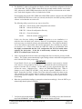
NOTE
When an option is enabled for the first time (normally at the Diamond factory), the
G1000 writes its unique system ID to the physical card and locks the files to this unique
ID. This prevents the unlock card from ever being used to activate the feature in other
G1000 systems. The unlock card is forever tied to the specific aircraft in which it was
used for the first time. For situations where the feature must be re-activated, this card
must be used. If the original G1000 feature unlock card is not available the technician
may purchase the unlock cards as a higher – level assembly produced by Garmin, defined
per the 010 – P/Ns shown above or contact Garmin customer support.
G1000 System Maintenance Manual – Diamond DA40/40F
190-00545-01
Page 1-15
Revision G
This page intentionally left blank.
Page 1-16
Revision G
G1000 System Maintenance Manual – Diamond DA40/40F
190-00545-01
2
2.1
SYSTEM DESCRIPTION
STC Requirements Overview
The -1 and -2 STC configurations require the following STCs to be installed on the aircraft prior or
concurrently to the installation of this STC:
STC #SA01254WI-D
Garmin G1000 in Diamond DA40 / 40F
STC #SA01389WI
Garmin GFC 700 in Diamond DA40 / 40F
For the -3, -4, -5, and -6 configurations of this STC, only STC #SA01254WI-D is required to be installed.
Certain Diamond Optional Aircraft Modifications (OAM) are part of the initial type design requirements
for the above STCs. These modifications define much of the systems and electrical design for the Garmin
G1000 and GFC 700 and are installed by the Diamond factory. The following OAMs may be installed on
a DA40 equipped with the G1000, depending on STC configurations:
DA40 & DA40F Aircraft:
OAM 40-226
G1000/GFC700 Provisions
OAM 40-061
KAP 140 Autopilot (Optional)*
OAM 40-068
Essential Bus
OAM 40-073
Slick Start System
OAM 40-082
IFR Lightning Protection
OAM 40-146
Remote Avionics Provisions
OAM 40-071
Extended Range Fuel Tanks
OAM 40-162
G1000 with Extended Range Fuel Tanks
OAM 40-210
Provisions for Becker RA3502 ADF
OAM 40-211
Provisions for Honeywell KN63 DME
OAM 40-213
Provisions for Garmin GDL 69A
DA40 Aircraft Only:
OAM 40-161
G1000 Provisions with KAP 140*
OAM 40-196
G1000 Provisions without KAP 140
STC #SA1840SC Hartzell Propeller
DA40F Aircraft Only
OAM 40-222
G1000 in DA40F Provisions
*Currently only supported by the -5 and -6 STC configurations. The KAP140 Autopilot has been certified for use with G1000
System Software version 0321.17 or later by this STC.
G1000 System Maintenance Manual – Diamond DA40/40F
190-00545-01
Page 2-1
Revision G
2.2
Equipment Descriptions
2.2.1
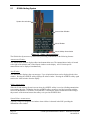
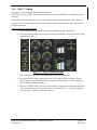
GDU 1040 PFD & GDU 1040, 1042, or 1044 MFD
Two Garmin GDU 1040 displays are installed in the Diamond instrument panel. One is configured as a
PFD and the other as a MFD (Configuration is determined by wiring harness). Both displays provide
control and display of nearly all functions of the G1000 integrated cockpit system. The displays are
located side-by-side with the GMA 1347 Audio Panel located in the middle. For GFC 700-equipped
aircraft, the MFD is either a GDU 1042 or GDU 1044. Both are distinguished by their dedicated AFCS
control keypad on the lower left bezel. The GDU 1044 has an additional VNV key which allows for
coupled-VNAV descents.
Electrical power to the PFD is from the ‘Essential’ power bus, whereas the MFD receives power from the
‘Main’ power bus. Therefore, both displays power-up immediately when the aircraft master switch is
turned on. To provide proper electrical bonding, beryllium copper ‘finger’ strips are installed on the
lower lip of the display. This provides sufficient contact area to which the displays can be grounded to
the airframe.
Both displays are installed in the Diamond panel using built-in ¼-turn fasteners. Each display uses an
existing connector per OAM 40-161 or OAM 40-226.
Two cooling fans are also installed behind the panel for PFD and MFD cooling.
For MDL configurations -1,-3 and -5 only, this STC installation approves alternate part numbers for the
displays that accept external video input and have an additional HSDB Ethernet connection. There are no
mechanical or electrical interface changes needed for these new part number displays. Refer to the
applicable General Arrangement Drawing listed in Table 1-2 for part number information.
NOTE
While the alternate part numbers of displays authorized by this STC include an external
video input and HDSB Ethernet connection, this STC does not approve any interfaces to
these ports. These ports are not configured on by this STC. Any interfaces to these ports
will require activation of these ports and additional airworthiness approvals will be
required.
2.2.2
GMA 1347 Audio Panel
The Garmin GMA 1347 Audio Panel is a digital audio panel with integrated marker beacon receiver. The
GMA 1347 provides control of all cockpit intercom/mic systems as well as NAV/COM/ILS audio. The
unit also provides display reversion mode control through a large red button. Power is received from the
‘Essential’ bus. The unit powers up when the aircraft master switch is turned on. The GMA 1347
interfaces with the existing marker beacon antenna as well as existing mic and phone jacks.
Page 2-2
Revision G
G1000 System Maintenance Manual – Diamond DA40/40F
190-00545-01
2.2.3
GIA 63 or GIA 63W Integrated Avionics Unit (2)
NOTE
For MDL configurations -1,-3 and -5 only, this STC installation approves alternate part
number ‘-20’ GIA63Ws. The installation of these units will require software version
0321.23 or later as well as mechanical and wire harness changes to relocate the GTX33
transponders (refer to Section 2.2.5). Refer to the applicable General Arrangement
Drawing listed in Table 1-2 for part number and software information.
Two Garmin GIA 63 IAUs provide VHF COM, NAV, GS, and GPS navigation functions to the G1000.
GIA 63W models include a GPS/WAAS engine. GIAs also serve as a communication interface to all
other G1000 LRUs in the system. Both GIAs are located remotely beneath the baggage compartment in a
sheetmetal enclosure. The #1 GIA is powered through the ‘Essential’ power bus and immediately powers
up when the aircraft master switch is turned on. The #2 GIA receives power through the ‘Main Avionics’
bus and powers up when the avionics master switch is turned on. Both GIA 63s interface to the following
equipment:
•
Existing VOR/LOC/Glideslope Antenna System
•
Existing VHF COM 1 & 2 Antennas
•
Existing Garmin GA56 GPS1 & 2 Antennas (GIA 63 only)
•
GA35 GPS/WAAS Antennas (GIA 63W only)
2.2.4
GEA 71 Engine/Airframe Unit
The Garmin GEA 71 Engine/Airframe Unit provides engine/airframe data to the G1000 system. Data
received from transducers/sensors is processed, then sent to GIA 63, and subsequently to the GDU 1040
MFD. In display reversionary mode, engine instrumentation is displayed on the PFD as well. The GEA
is located behind the instrument panel and is mounted in a vertical orientation. Power is received from
the ‘Essential’ power bus. The GEA interfaces to the following:
•
Manifold Pressure Sensor (MAP, DA 40 aircraft only)
•
Oil Pressure Sensor
•
Fuel Pressure Sensor
•
Tachometer Sensor
•
Oil Temperature Sensor
•
Fuel Flow Sensor
•
4 Cylinder Head Temperature (CHT) Sensors
•
4 Exhaust Gas Temperature (EGT) Sensors
•
Alternator Current Sensor
•
Existing Fuel Probes
•
Existing Pitot Heat System
•
Existing Open Door Detection Switches
•
Existing Starter Engage System
NOTE
STC SA01254WI-D provisions engine/airframe sensors for the Diamond DA 40 aircraft
only. For DA 40 F aircraft with fixed-pitch propellers, all engine sensors are provisioned
and installed per Diamond OAM 40-222.
G1000 System Maintenance Manual – Diamond DA40/40F
190-00545-01
Page 2-3
Revision G
2.2.5
GTX 33 Mode S Transponder
The Garmin GTX 33 provides Mode A, C, and S altitude and position reporting information to the G1000
system.
• Aircraft with GIA 63W P/N 011-01105-00 or 011 01105-01, the unit is mounted in the remote
avionics enclosure below the baggage compartment.
•
Aircraft with GIA 63W P/N 011-01105-20, the unit is mounted on the outboard side of the
remote avionics enclosure below the baggage compartment.
Power is received from the ‘Essential’ bus. The GTX 33 interfaces with the existing transponder antenna.
2.2.6
GDC 74A Digital Air Data Computer
The Garmin GDC 74A provides digital air data computations to the G1000 system. The unit is mounted
horizontally behind the instrument panel and is fastened to a rack. Power is received from the ‘Essential’
bus. The GDC 74A connects to existing pitot/static ports.
2.2.7
OAT Probe
The Garmin GTP 59 OAT Probe provides the GDC 74A with air temperature data. The OAT probe is
mounted to the bottom starboard side of the DA 40 fuselage.
2.2.8
GRS 77 Attitude & Heading Reference System
The Garmin GRS 77 AHRS provides attitude and heading information to the G1000 system. The unit is
mounted remotely in the baggage compartment, to the starboard side of the remote avionics enclosure.
Power is received from the ‘Essential’ bus. The GRS 77 interfaces with and provides power to the
GMU 44 Magnetometer. The GRS 77 supplies attitude and heading information directly to the PFD,
MFD, and to both GIAs.
2.2.9
GMU 44 Magnetometer
The GMU 44 provides horizontal and vertical magnetic field information to the GRS 77 AHRS. This
allows heading to be calculated and provides assistance during AHRS alignment. The GMU 44 is
mounted beneath the starboard wing.
2.2.10 GDL 69A (Optional)
The GDL 69A provides optional XM Radio weather and music entertainment through means of a
dedicated satellite data link. The GDL 69A is mounted in the remote avionics enclosure. Power to the
GDL 69A is received from the ‘Main Avionics’ bus. The GDL 69A sends weather data through the
HSDB bus to the MFD, where the data link interface is controlled. Digital audio is sent directly to the
GMA 1347.
2.2.11 Remote Avionics Enclosure
Refer to 005-00304-00, Sheets 2 & 8:
A remote avionics enclosure allows LRUs to be inserted vertically, from above. The enclosure is also
cooled with an avionics fan and duct assembly. The assembly is grounded to an existing grounding
station using a field-fabricated aluminum ground strap. Two braided grounding straps are also attached to
the GRS 77 rack from the enclosure. A Comant diplexer is installed on the enclosure as shown. A fieldfabricated component bracket with resistors, voltage suppressors and attached wiring is fastened to the
forward portion of the enclosure.
Page 2-4
Revision G
G1000 System Maintenance Manual – Diamond DA40/40F
190-00545-01
2.2.12 GDL 59 Datalink (Optional)
The GDL 59 provides the interface to an optional GSR 56 satellite datalink, which adds airborne low
speed data link and voice communication capability. The GDL 59 unit interfaces to the Garmin
Integrated Flight Deck via the GDL69A using HSDB. The GDL 59 is located below the baggage
compartment and power is received from the Avionics bus.
2.2.13 GSR 56 Satellite Transciever (Optional)
The GSR 56 provides airborne low speed data link and voice communication capability to Garmin
Integrated Flight Deck installations. The GSR 56 contains a transceiver that operates on the Iridium
Satellite network. The GSR 56 interfaces directly to the GDL 59 via an RS-232 interface for the
GDL 59 / GSR 56 combination option. The Standalone GSR 56 option interfaces directly to GIA #2 via
an RS-232 interface. The GSR 56 is located below the baggage compartment and power is received from
the Avionics bus.
2.3
G1000 Optional Interfaces
Installation of all other optional equipment that interfaces to the G1000, including ADF, DME, and
GDL 69A is documented by Diamond OAM factory drawings.
2.3.1
KAP 140 AFCS
The Phase 7 amendment to STC SA01444WI-D adds two new installation configurations to the MDL
(See Table 1-1), both of which allow for G1000 systems with GDU 8.20 and greater to interface with
existing DA40 aircraft equipped with the Honeywell KAP 140 AFCS.
The G1000 interfaces to the KAP 140 by providing the following from the #2 GIA 63:
-Output of Lateral & Vertical Navigation Signals
-Output of Course Datum
-Output of Heading Datum
-Output of Encoded Altitude
-ILS Energize Discrete
-GPS Select Discrete
Additionally, the G1000 receives the following from the KAP 140:
-Pitch Trim Fail Discrete Input
-Pitch Trim Fail Aural Input
The G1000 – KAP 140 interface was included as part of the original G1000 certification under STC
SA01254WI. In order to be compatible with WAAS, GDU software changes were made as part of
System Software Version 0321.17 or later, which were certified as a follow-on amendment to STC
SA01444WI-D.
2.3.2
Synthetic Vision System
The Synthetic Vision System (SVS) provides the crew with a greater awareness of the aircraft’s position
relative to surrounding terrain, obstacles, and traffic (optional). SVS is an embedded software feature of
the G1000 and is controlled by using PFD softkeys. Specific details on operating the SVS feature can be
found in the Synthetic Vision & Pathways AFMS specified in Table 1-4.
SVS enhances situational awareness by displaying a three dimensional depiction of terrain, obstacles, and
traffic in the PFD primary field of view such that their proximity to the aircraft is more easily understood
during instrument scanning. The display of SVS can be turned on and off by the pilot by a dedicated
softkey on the PFD.
G1000 System Maintenance Manual – Diamond DA40/40F
190-00545-01
Page 2-5
Revision G
The SVS PFD frame-of-reference is aligned with the aircraft body frame, using AHRS attitude and
heading data for orientation. Accordingly, the SVS is egocentric and attitude-aligned. GPS position and
GPS-derived altitude are used for the SVS position and elevation references, respectively. The SVS 3D
terrain presentation is generated from a high resolution 9 arc-second terrain database image. For the SVS
system to be made available by the G1000, valid attitude, heading, GPS position, and terrain databases are
required.
All previous existing PFD display features are retained and drawn over the SVS. For example, airspeed,
altitude, vertical speed, heading, and HSI items will remain unchanged, and will be drawn over the SVS
presentation.
Figure 2-1. SVS/Pathways Feature
Synthetic Vision System:
3D Terrain Rendering on PFD – SVS system will utilize an egocentric, forward looking perspective of 3D
terrain rendering and shading, to be displayed on the PFD.
Zero Pitch Line – The PFD displays an artificial horizon pitch reference line above the display of terrain,
similar to the existing artificial horizon which currently separates the blue/brown attitude depiction. The
display of horizon heading marks in 30° intervals on the pitch line is a pilot-selectable feature.
Flight Path Marker – The projected aircraft flight path is displayed in the form of a Flight Path Marker on
the PFD.
Display of Traffic – Traffic data from existing certified TIS, provided by the G1000 GTX 33 Mode-S
transponder, is used to generate on-screen traffic symbols.
Display of Land-based Objects – Obstacles, runways, water bodies, and other land features are displayed
on the PFD.
Pathways:
Page 2-6
Revision G
G1000 System Maintenance Manual – Diamond DA40/40F
190-00545-01
SVS / Pathways are a pilot-selectable feature. The display of SVS can be turned on and off by the pilot by
a dedicated softkey on the PFD. The display of Pathways requires that the 3D Terrain feature be
displayed (i.e. SYN TERR softkey pressed).
When active, the Pathway is displayed on the PFD and will show flight path information in the form of a
virtual 3D flight path, composed of rectangular elements which form a tunnel. The depiction of this
pathway is derived from the existing FMS navigation capabilities of the G1000, and the display will be
consistent with that of the active flight plan shown on the MFD.
2.4
GFC 700 AFCS System Description
For system software versions 0321.22 and earlier there was only one GFC 700 option which is
represented by the Standard GFC 700 description listed below.
•
GFC 700 - GSM 85 Servo Gearbox and GSA 81 Servo Actuator
(P/N 011-00878-00)
For system software version 0321.23 and later the GFC 700 AFCS System has two (2) possible
installation options.
Dependent on the desired aircraft configuration the appropriate option will be selected and loaded. The
two options are listed below:
•
•
Standard GFC 700 - GSM 85 or GSM 86 Servo Gearbox and GSA 81 Servo Actuator
(P/N 011-00878-00)
Enhanced GFC 700 – GSM 86 Servo Gearbox (P/N 011-01904-03) and GSA 81 Servo
Actuator (P/N 011-00878-20)
Enhanced GFC 700:
An option for GFC 700 with GSM 86 Servo Gearbox (P/N 011-01904-03) and GSA 81 Servo Actuator
(P/N 011-00878-20) is available to the DA40 / DA40F. For this option the GSA 81 Pitch, Pitch Trim,
and Roll Servos software has been introduced at version 3.11. This option was added to allow enhanced
LRU and system operation and is a requirement for future GFC 700 functionality.
New functionality provided by the Enhanced GFC 700 option is as follows:
•
•
•
GSM Automated Slip Clutch Torque Check
Autopilot Expanded Engagement
Aural AIRSPEED alert
G1000 System Maintenance Manual – Diamond DA40/40F
190-00545-01
Page 2-7
Revision G
Standard GFC 700:
The Standard GFC 700 with GSM 85 or GSM 86 Servo Gearbox and GSA 81 Servo Actuator
(P/N 011-00878-00) is maintained as the previously certified configuration.
The Standard or Enhanced GFC 700 is a two-axis fail-safe digital flight control system that is integrated
within the G1000 system. The only distinguishing hardware from a non autopilot G1000 installation is
the MFD, the GSA 81 Servos and GSM 85 or GSM 86 Servo Mounts.
The following functions are provided by the GFC 700 in this installation:
•
•
•
Flight Director
Autopilot
Manual Electric Trim
Flight Director:
The Flight Director operates within the #1 GIA 63 and uses data from the G1000 system, including air
data, attitude, and navigation data, to calculate commands for display to the pilot and for the Autopilot.
Flight Director command bars and mode annunciations are sent to the PFD through a high-speed Ethernet
connection for display to the pilot. The Flight Director operates independently of the Autopilot, and
allows the pilot to hand-fly the command bars, if desired.
Autopilot:
The Autopilot operates within the three GSA 81 servos. Flight Director data is processed within the three
servos and turned into aircraft flight control surface commands. The Autopilot cannot operate unless the
Flight Director is engaged.
Manual Electric Trim:
Independent of the Flight Director and Autopilot, Manual Electric Trim (MET) allows the pilot to control
the elevator trim tab by the MET switch located on the pilot control stick. Engaging both sides of the
switch in the same direction causes the autopilot to disengage (if engaged) and drives the pitch trim servo
in the desired direction. The ARM side of the MET switch may also be used to disconnect the autopilot
and cancel the resulting AP DISC alerts.
Page 2-8
Revision G
G1000 System Maintenance Manual – Diamond DA40/40F
190-00545-01
Figure 2-2. AFCS System Block Diagram
G1000 System Maintenance Manual – Diamond DA40/40F
190-00545-01
Page 2-9
Revision G
2.4.1
GFC 700 Electrical Aspects
The wiring and switches used by the GFC 700 are provisioned by Diamond under OAM 40-226, and are
not included in the Garmin GFC 700 STC design. In general, the pitch and pitch trim servos are wired in
parallel to both GIA 63s and use the RS-485 serial protocol to communicate while the pitch servo has its
own line to both GIAs. See the Diamond wiring diagrams listed in Table 1-2 for more details on wiring.
The Diamond provisions also include the following switches:
AP DISC Switch
There are two large red AP DISC switches located on the pilot and copilot control sticks. When normally
closed, +28 VDC is allowed to pass through to the SERVO ENABLE pins of each servo, allowing the
Autopilot and servos to operate. When pushed, the switches break the +28VDC source and the Autopilot
disconnects and takes the servos offline.
CWS Switch
A control wheel steering switch is located on the pilot’s control stick. When pressed, this switch activates
CWS mode. The Autopilot, if engaged, is temporarily disengaged, and the Flight Director command bars
immediately synchronize to the current aircraft pitch and roll attitude. When released, the Autopilot will
re-engage (if previously engaged) and the Flight Director will orient itself to the last known pitch and roll
reference established during CWS mode. This allows the pilot to hand fly the aircraft when desired and
also allows the pilot to reestablish a desired aircraft flight attitude for the Autopilot to maintain.
MET Switch
See previous functional description of MET.
GA Switch
A Go-Around switch is installed within the engine throttle knob and activates the GA Flight Director
mode. During this mode, the Autopilot disengages (if engaged) and the Flight Director displays a 7° pitch
up nose attitude for reference during a missed approach or go-around procedure.
Page 2-10
Revision G
G1000 System Maintenance Manual – Diamond DA40/40F
190-00545-01
2.4.2
GSA 81 Servo and GSM 85 or GSM 86 Servo Mount
Figure 2-3. GSA 81 & GSM 85 or GSM 86
The GSA 81 is mated to the GSM 85 or GSM 86 Servo Mount to form a single servo unit. There are
three servo units in this installation:
Pitch
•
Pitch Trim
•
Roll
The design of the servo assembly allows the servo actuator (GSA 81) to be removed from the servo
mount (GSM 85 or GSM 86) without the need to de-rig the aircraft control cables. The servo mount
contains the capstan (cable for roll/pitch, chain for pitch trim) and the slip clutch which allows a pilot to
manually overpower the Autopilot.
•
The GSM 85 has a slip clutch that can be adjusted to a desired torque value. The GSM 86 has a clutch
cartridge that cannot be adjusted to a different torque value.
2.5
Envelope Stability & Protection Description
System software version 0321.23 and later supports the optional Electronic Stability and Protection (ESP)
function. ESP assists the pilot in maintaining a safe flight condition within the aircraft flight envelope,
defined by pitch, roll, and airspeed. ESP is only active during flight with the autopilot off, and is only
available on G1000-equipped DA40 aircraft that also have a GFC 700 autopilot with the Enhanced AFCS
option installed.
ESP is automatically enabled when the aircraft exceeds one or more pre-determined thresholds beyond
normal flight. ESP engages the appropriate servo(s) in protection mode with low torque and gradually
increases the stick forces so the airplane naturally returns back to the desired flight envelope. The DA40
ESP activation thresholds are as follows:
•
Roll threshold activation is 45 degrees for both the left and right roll conditions.
•
Pitch threshold activation is 15 degrees for pitch up and 18 degrees for pitch down.
•
High Airspeed threshold activation is 180 Knots Indicated Airspeed (KIAS) for high airspeed.
As the airplane deviates further from the desired flight envelope, the servo torque is increased in the
direction required to return to the desired flight envelope until the maximum torque level is reached. As
the airplane continues to deviate, the torque level remains constant up to the maximum engage limit.
G1000 System Maintenance Manual – Diamond DA40/40F
190-00545-01
Page 2-11
Revision G
Above the maximum engage limit, ESP is not provided. The maximum thresholds for deactivation of the
ESP system on the Diamond DA 40 are as follows:
•
Roll threshold deactivation outside of normal roll envelope is 75 degrees for both the left and
right roll conditions.
•
Roll threshold deactivation returning to normal roll envelope is 30 degrees for both the left and
right roll conditions.
•
Pitch threshold deactivation outside of normal pitch envelope is 20 degrees for pitch up and 23
degrees for pitch down.
•
Pitch threshold deactivation returning to normal pitch envelope is 10 degrees for pitch up and 13
degrees pitch down.
•
High Airspeed threshold deactivation occurs when the normal airspeed is 175 KIAS.
Once ESP protection is being provided and ESP is active for 50% of the last 20 seconds, the autopilot
engages in LVL mode returning the aircraft to a level flight envelope. When the autopilot engages
automatically an aural “ENGAGING AUTOPILOT” alert sounds and the Flight Director mode
annunciations will indicate LVL for the pitch and roll modes.
The pilot can interrupt the ESP function in manual flight by pressing and holding either the Control
Wheel Steering (CWS) or Autopilot Disconnect (AP DISC) switch. ESP can also be overridden by
overpowering the servo’s ESP electronic torque limit.
ESP and Autopilot are mutually exclusive functions and have separate electronic torque limits for its
specific function.
The pilot may also disable ESP by accessing the Multi-Function Display (MFD) Auxiliary System Setup
page on the MFD and manually disabling ESP. If the MFD circuit breaker is cycled while on the ground
or in flight the G1000 system will default ESP to “Enabled”. An advisory message is posted on the
G1000 when ESP is disabled
Page 2-12
Revision G
G1000 System Maintenance Manual – Diamond DA40/40F
190-00545-01
2.6
Electrical Power Distribution
Distribution of power to the G1000 occurs on three buses:
Essential Bus: The ‘Essential’ bus is tied directly to the aircraft battery via the master switch. When the
master switch is turned on, power is immediately supplied the ‘Essential’ bus. The ‘Essential’ bus is tied
via a relay switch to the ‘Main’ aircraft bus. There are two circuit breakers on either side of the relay,
combined with a single diode, allowing the battery to be charged by the alternator. Only equipment
deemed essential for safe flight is connected to this bus.
Main Aircraft Bus: The ‘Main’ bus receives power from the aircraft battery when tied to the ‘Essential’
bus. After the aircraft engine is started, the alternator supplies power to the aircraft ‘Main’ bus, and to the
rest of the system. In the event of an alternator or other power failure, the ‘Essential’ bus can be isolated
with the ‘Essential Bus’ switch. This causes the ‘Essential’ bus to revert to battery power. Only the MFD
receives power from the ‘Main’ bus.
Main Avionics Bus: A ‘Main Avionics’ bus is tied to the ‘Main’ aircraft bus via the ‘Avionics Master’
switch and switch relay. The #2 GIA 63, the ADF, DME, GFC 700 AFCS, and the GDL 69A are
connected to this bus.
G1000 System Maintenance Manual – Diamond DA40/40F
190-00545-01
Page 2-13
Revision G
N O T E : T H E S E IT E M S N O T
IN C L U D E D IN T H E M D L -3/-4
'N O A U T O P IL O T'
C O N F IG U R A T IO N S
N O T E : T H E G D L 5 9 A N D G S R 5 6 A R E O P T IO N A L IN S T A L LA T IO N S .
T H E G S R 5 6 M A Y B E IN S TA LL E D A S A S T A N D -A L O N E U N IT . T H E
IR ID IU M C IR C U IT B R E A K E R IS S IZ E D A T 2 A M P S F O R A C O M B IN E D
G D L 5 9 /G S R 5 6 IN S T A L L A T IO N A N D 1 A M P F O R A S T A N D -A LO N E
G S R 5 6 IN S T A L LA T IO N .
Figure 2-4. G1000/DA40 Electrical Distribution (GFC 700 Aircraft)
Page 2-14
Revision G
G1000 System Maintenance Manual – Diamond DA40/40F
190-00545-01
N O T E : T H E G D L 5 9 A N D G S R 5 6 A R E O P T IO N A L IN S T A L LA T IO N S .
T H E G S R 5 6 M A Y B E IN S T A L L E D A S A S T A N D -A L O N E U N IT . T H E
IR ID IU M C IR C U IT B R E A K E R IS S IZ E D A T 2 A M P S F O R A C O M B IN E D
G D L 5 9 /G S R 5 6 IN S T A L L A T IO N A N D 1 A M P F O R A S T A N D -A L O N E
G S R 5 6 IN S T A LL A T IO N .
Figure 2-5. G1000/DA40 Electrical Distribution (KAP140 Aircraft)
G1000 System Maintenance Manual – Diamond DA40/40F
190-00545-01
Page 2-15
Revision G
2.7
Lightning Strike Protection
The following modifications to the aircraft provide additional protection of G1000 equipment from the
effects of lightning strike.
2.7.1
Alternator / Battery Voltage Suppressors & Fuses
Refer to 005-00304-00, Sheet 5:
Two Transient Voltage Suppressors (TVS) are installed behind the instrument panel near the circuit
breakers. Voltage suppressors help protect the avionics/electrical equipment against the effects of lighting
strike. One voltage suppressor is connected to the load side of the aircraft battery circuit breaker, and the
other is connected to the line side of the alternator circuit breaker. One 3.2 Amp slow-blow fuse is wired
in line with each voltage suppressor. Fuses are easily removed by twisting the fuse holder cap counterclockwise and removing the fuse.
2.7.2
GIA / AHRS Lightning Protection
Refer to 005-00304-00, Sheets 8, 10 & 11:
The GRS 77 and both GIA 63s are uniquely protected from the effects of lightning. A 0.499Ω resistor, a
transient voltage suppressor, and a 3.2 Amp slow-blow fuse are used for each GIA and the AHRS. These
components are installed on a field-fabricated aluminum block, which is mounted to the front of the
remote avionics enclosure. Power leads for the AHRS and both GIAs are routed from the aircraft harness
to a 9-pin connector (P900), whose mating connector is mounted to the fabricated block (J900). Power is
returned to the LRU after passing through the resistor and voltage suppressor.
Refer to 005-00400-12:
For WAAS-equipped aircraft, seven additional resistors are installed on a sheetmetal bracket on the side
of the remote avionics box. Three resistors are inline between the #1 GIA 63W and GRS 77 RS-232
serial communications line and four are inline between the #1 GIA 63W and PFD High Speed Data Bus
(HSDB) cable.
2.7.3
Lightning Strike Maintenance
Proper electrical bonding of all metallic components is critical for the protection against the effects of
lighting. Severe corrosion may inhibit a component’s ability to bond to the aircraft’s electrical ground
plane. The following summarizes maintenance practices which are implemented to maintain adequate
lightning protection for the aircraft. See Section 4, Table 4-1 for exact maintenance requirements and
associated intervals:
•
Annual visual inspection of all G1000 equipment, including voltage suppressors, resistors, fuses,
etc.
•
An electrical bonding check of G1000 equipment every 1000 hours or anytime a lightning strike
occurs or is suspected.
•
Regular replacement (every 24 calendar months) of all five 3.2 Amp slow-blow fuses ensures
they are in fresh condition.
•
Replacement of voltage suppressors, resistors, and fuses anytime a lightning strike occurs or is
suspected.
Page 2-16
Revision G
G1000 System Maintenance Manual – Diamond DA40/40F
190-00545-01
2.8
Shield Block Grounds
Most G1000 connectors employ a Shield Block grounding system to provide necessary ground reference
to wire shielding and/or transducers. The shield block termination method allows multiple grounds to be
terminated directly to a block mounted to the connector backshell assembly. Refer to G1000/DA40
Install Drawing, 005-00304-00 for installation details. Note that pre-2008 G1000 installations may
employ a slightly different shield grounding system called a “SPIDER” system. Note that aircraft
changing from a FAA certification to an EASA certification will require changing the SPIDER grounding
system to the shield block method.
2.9
Sensor Installations
Refer to 005-00304-00, Sheets 5, 9, & 12 for the engine sensor installation drawings.
2.10
Block Diagrams
2.10.1 G1000 & KAP140
Figure 2-6. G1000/KAP 140 Block Diagram (no WAAS)
G1000 System Maintenance Manual – Diamond DA40/40F
190-00545-01
Page 2-17
Revision G
2.10.2 G1000 & GFC700
Figure 2-7. G1000/GFC 700 Block Diagram (WAAS shown)
Page 2-18
Revision G
G1000 System Maintenance Manual – Diamond DA40/40F
190-00545-01
3
G1000 Control & Operation
All control and operation of G1000 equipment as normally used in flight occurs through the PFD, MFD
and GMA 1347 audio panel. Figure 3-1 identifies GDU 1040 buttons. Figure 3-3 identifies various
GMA 1347 buttons.
Figure 3-1. GDU 104X Control Interface (GDU 1042 shown)
3.1.1
AFCS Controls
The dedicated AFCS controls located on the GDU 1042 and 1044 are discussed in detail in the G1000
CRG. The following figure is provided for reference:
Figure 3-2. AFCS Controls (GDU 1044 shown)
G1000 System Maintenance Manual – Diamond DA40/40F
190-00545-01
Page 3-1
Revision G
3.1.2
GMA 1347 Controls
The controls located on the GMA 1347 are discussed in detail in the G1000 CRG. The following figure
is provided for reference:
Figure 3-3. GMA 1347 Controls
3.1.3
FMS Knob
The FMS knob is the primary control for the G1000 system. Operation is similar to the Garmin
400/500 Series units.
•
To cycle through different configuration screens:
To change page groups: Rotate the large FMS knob.
To change pages in a group: Rotate the small FMS knob.
•
•
•
•
•
To activate the cursor for a page, press the small FMS knob directly in, as one would push a
regular button.
To cycle the cursor through different data fields, rotate the large FMS knob.
To change the contents of a highlighted data field, rotate the small FMS knob. This action either
brings up an options menu for the particular field, or in some cases allows the operator to enter
data for the field.
To confirm a selection, press the ENT key.
To cancel a selection, press the small FMS knob in again, deactivating the cursor. The CLR key
may also be used to cancel a selection or deactivate the cursor.
Page 3-2
Revision G
G1000 System Maintenance Manual – Diamond DA40/40F
190-00545-01
3.1.4
Softkeys
Some pages have commands or selections that are activated by the GDU 1040 softkeys. If a softkey is
associated with a command, that command will be displayed directly above the key. A grayed-out
softkey shows a command that is unavailable. A softkey that is highlighted shows the current active
selection.
Figure 3-4. G1000 Softkeys
3.2
G1000 Operation Modes
3.2.1
Normal Mode
To start the G1000 system in Normal Mode:
1. Turn on the aircraft master switch. The following G1000 equipment is powered on:
•
PFD & MFD (MFD receives power only if ‘Essential Bus’ switch is OFF)
•
GRS 77 AHRS
•
GDC 74A Air Data Computer
•
No. 1 GIA 63 Integrated Avionics Unit
•
GEA 71 Engine/Airframe Unit
•
GTX 33 Mode S Transponder
•
GMA 1347 Digital Audio Panel
2. Turn on the DA 40 AVIONICS MASTER switch. The following G1000 equipment is powered
on:
•
No. 2 GIA 63 Integrated Avionics Unit
•
GFC 700 (if equipped)
•
GDL 69A (if equipped)
The G1000 system is now powered in the normal mode. The PFD and MFD will function as specified in
the G1000/DA 40 Cockpit Reference Guide, when the system has been correctly installed and configured.
Figure 3-5. Normal Mode
G1000 System Maintenance Manual – Diamond DA40/40F
190-00545-01
Page 3-3
Revision G
3.2.2
Reversionary Mode
Should a display communication or hardware failure occur, the G1000 system automatically enters the
reversionary mode. The system reversionary mode forces the remaining display into showing all
information related to safe flight.
A manual reversionary mode also allows the operator to force the system into reversionary mode in
situations where the system does not automatically enter reversionary mode. A large red button labeled
‘DISPLAY BACKUP’ on the GMA 1347 audio panel activates the manual reversionary mode.
Figure 3-6. MFD Failure Mode
Should the PFD display fail, the MFD automatically enters reversionary mode. In this mode, flightcritical information from the AHRS/Air Data system is displayed on the MFD along with essential engine
instrumentation.
Figure 3-7. PFD Failure Mode
Page 3-4
Revision G
G1000 System Maintenance Manual – Diamond DA40/40F
190-00545-01
3.3
G1000 Configuration Mode Overview
The Configuration Mode exists to provide the avionics technician with a means of configuring, checking,
and calibrating various G1000 sub-systems. Troubleshooting and diagnostics information can also be
viewed in this mode.
To start the system in Configuration Mode:
1. Start the system in normal mode as described in Section 3.2.1.
2. Remove power to the PFD and MFD by pulling the circuit breakers labeled PFD and MFD.
3. Press and hold the ENT key on the PFD while applying power using the PFD circuit breaker.
4. Release the ENT key after ‘INITIALIZING SYSTEM’ appears in the upper left corner of the
PFD.
5. Power on the MFD in the same manner. You must have both displays in Configuration Mode
whenever performing post-installation practices.
NOTE
It is good practice to cycle power to the entire G1000 system, not just the displays,
anytime software loading, configuration or other maintenance procedures have been
completed.
CAUTION
The Configuration Mode contains certain pages and settings that are critical to aircraft
operation and safety. These pages are protected and cannot be modified, unless the
technician is properly authorized and equipped. However, most protected pages are
viewable to allow system awareness for troubleshooting.
NOTE
For a complete description and breakdown of each Configuration Mode page, refer to the
G1000 Line Maintenance & Configuration Manual, Garmin part number 190-00303-04.
NOTE
Throughout this document when performing configuration or software uploads reference
is made to two fields, “AIRFRAME” and “FILE for software versions SW v0321.19 or
earlier and “GROUP” and ITEM for SW v0321.22 or later. When either of these terms is
referenced in this document their function is synonymous for the specific items being
loaded.
Figure 3-8. SYSTEM UPLOAD FIELDS (SW v0321.19 or earlier)
Figure 3-9. SYSTEM UPLOAD FIELDS (SW v0321.22 or later)
G1000 System Maintenance Manual – Diamond DA40/40F
190-00545-01
Page 3-5
Revision G
3.3.1
SET>ACTV Configuration
Throughout the configuration mode pages, there are SET and ACTIVE columns for input/output settings
and other parameters.
SET:
Refers to a setting or group of settings that reside in PFD internal memory.
ACTIVE: Refers to a current setting stored and used in a LRU. LRUs store the ‘active’ settings
within internal memory.
Data can be manually copied from one column to the other (and consequently from PFD memory to the
LRU memory and vice-versa) by using the following two softkeys, when available:
•
SET>ACTV (read ‘Set to Active’) softkey: Allows the technician to send the information in the SET
column (data stored in PFD internal memory) to the ACTV column (data used by LRU).
•
ACTV>SET (read ‘Active to Set’) softkey: Causes the LRUs current settings to be copied to PFD
internal memory as SET items.
CAUTION
It is highly recommended that the ACTV>SET softkey not be used unless specifically
instructed by this manual. If the ACTV>SET softkey is used it should be used with
caution! If an improperly configured unit is installed, this softkey causes the wrong
configuration to replace the correct aircraft configuration.
In the first example shown in Figure 3-10, the SET columns do not match the ACTIVE columns. The
inequality between SET and ACTIVE indicates a configuration mismatch and triggers a configuration
error message for the LRU. By pressing the SET>ACTV softkey, this copies the data shown in the SET
column to the LRU unit’s internal memory. The settings then become the ACTIVE settings for the LRU
being configured.
Page 3-6
Revision G
G1000 System Maintenance Manual – Diamond DA40/40F
190-00545-01
Configuration Mismatch
Master Configuration Module
LRU Memory
Master Configuration Module
=
LRU Memory
=
SET>ACTV Softkey
Master Configuration Module
LRU Memory
Master Configuration Module
LRU Memory
Configuration Correct
Master Configuration Module
LRU Memory
Master Configuration Module
=
LRU Memory
=
Figure 3-10. SET>ACTV Diagram
When troubleshooting configuration error messages, technicians can look for inequalities between SET
and ACTIVE columns which trigger the message. Some configuration error messages can be resolved
simply by pressing the SET>ACTV softkey, which reloads settings from the PFD to the specific LRU.
This can also be accomplished by reloading the configuration files for the LRU, using the approved
G1000 system software loader card for the currently installed software. Section 7 describes the process
for loading configuration files from a software loader card to a LRU).
A blank active column, as shown in Figure 3-11, represents loss of communication between the display
and the particular unit. See Section 5 for more details on troubleshooting loss of communications.
G1000 System Maintenance Manual – Diamond DA40/40F
190-00545-01
Page 3-7
Revision G
Figure 3-11. Loss of Communication
3.3.2
Configuration Prompts
When configuration settings are changed, the technician receives on-screen prompts and/or confirmations
such as those shown in Figure 3-11. Section 7 shows other prompts encountered during the configuration
process.
Figure 3-12. Configuration Status
Page 3-8
Revision G
G1000 System Maintenance Manual – Diamond DA40/40F
190-00545-01
3.3.3
Data Transmission Indicators
In addition to LRU status, indicator lights and symbols show the status of LRU/Channel data paths. This
can help in identifying a fault.
Table 3-1. Data Transmission Indicators
GDU Software before v0321.19
GDU Software for v0321.22 and greater
INDICATOR
MEANING
The LRU is online and reports
that the item located next to the
indicator box is communicating.
The LRU is online, and reports
that the item located next to the
indicator box is not
communicating.
The LRU is not reporting a
status for the item located next
to the indicator box. This may
be because the data is not
available, not applicable, or not
expected.
INDICATOR
MEANING
The LRU is online and reports that
the item located next to the indicator
box is communicating.
The LRU is online, and reports that
the item located next to the indicator
box is not communicating.
The LRU is not reporting a status for
the item located next to the indicator
box. This may be because the data is
not available, not applicable, or not
expected.
The LRU is not reporting status for
the item located next to the indicator
box. This may be due to the fact that
the data is not available or is not
expected.
“True” condition; i.e., necessary
conditions have met in order to
activate the item.
“False” condition; i.e., necessary
conditions have not been met in order
to activate the item.
“High” condition; i.e., the system
expects a high voltage or a high
resistance input to trigger the item
(fan operation, etc.)
“Low” condition; i.e., the system
expects a low voltage or a low
resistance input to trigger the item
(fan operation, etc.)
G1000 System Maintenance Manual – Diamond DA40/40F
190-00545-01
Page 3-9
Revision G
DATA PATH STATUS
Figure 3-13. Data Transmission Indicators
3.3.4
Configuration Mode Navigation
Using the FMS knob as described in Section 3.1.3, a user can navigate through different pages and page
groups in the Configuration Mode. For complete description and breakdown of each page, refer to the
G1000 Line Maintenance & Configuration manual, Garmin part number 190-00303-04.
The active page title is displayed at the top of the screen in the center. In the bottom right corner of the
screen, the current configuration page group, number of pages available in the group, and placement of
the current page within the group are indicated by icons.
NOTE
Certain "protected" configuration pages are critical to aircraft operation and safety. The
technician is unable to modify or change settings on these pages unless they are
authorized and equipped to do so. They are viewable to aid in troubleshooting.
Page Navigation tables specific to the applicable software versions start on the next page.
Page 3-10
Revision G
G1000 System Maintenance Manual – Diamond DA40/40F
190-00545-01
Table 3-2. Page Navigation SW v0321.19 or earlier
System Page Group
1. System Status
5. System Upload
9. System Configuration
2. Date/Time Setup
6. Diagnostics Terminal
10. System Setup
3. Main Lighting
7. Maintenance Log
11. Manifest Configuration
4. Audio Alert Configuration
8. OEM Diagnostics
GDU Page Group
1. RS-232 / ARINC 429
Configuration
4. Diagnostics
7. Alert Configuration
2. GDU Status
5. Serial/Ethernet I/O
8. Airframe Configuration
3. GDU Test
6. Alert Configuration
GIA Page Group
1. RS-232 / ARINC 429
Configuration
3. GIA I/O Configuration
2. CAN / RS-485 Configuration
4. COM Setup
5. GIA Status
GEA Page Group
1. Engine Data
2. GEA Status
3. GEA Configuration
GTX Page Group
1. RS-232 / ARINC 429
Configuration
2. Transponder Configuration
GRS Page Group
1. AHRS / Air Data Input
2. GRS / GMU Calibration
GDC Page Group
1. GDC Configuration
GFC Page Group
1. GFC Configuration*
2. GFC Status*
GMA Page Group
1. GMA Configuration
GDL Page Group
1. GDL 69 Configuration *
CAL Page Group
1. Fuel Tank Calibration
2. Flaps and Trim Calibration
3. HSCM Calibration
* If option is configured
G1000 System Maintenance Manual – Diamond DA40/40F
190-00545-01
Page 3-11
Revision G
Table 3-3. Page Navigation SW v0321.22
System Page Group
1. System Status
6. Diagnostics Terminal
10. System Setup
2. Date/Time Setup
7. Maintenance Log
11. Manifest Configuration
3. Main Lighting
8. OEM Diagnostics
12. Maintenance Log
4. Audio Alert
Configuration
9. System Configuration
5. System Upload
10. System Data Paths
GDU Page Group
1. RS-232 / ARINC 429
Configuration
4. Diagnostics
7. Airframe Configuration
2. GDU Status
5. Serial/Ethernet I/O
8. TAWS – B Setup
3. GDU Test
6. Alert Configuration
GIA Page Group
1. RS-232 / ARINC 429
Configuration
3. GIA I/O Configuration
5. GIA Status
2. RS-485 Configuration
4. COM Setup
6. CAN Configuration
GEA Page Group
1. Engine Data
2. GEA Status
3. GEA Configuration
GTX Page Group
1. RS-232 / ARINC 429
Configuration
2. Transponder
Configuration
GRS Page Group
1. AHRS / Air Data Input
2. GRS / GMU Calibration
GDC Page Group
1. ADC Configuration
2. GDC Configuration
GFC Page Group
1. GFC Configuration*
2. GFC Status*
GMA Page Group
1. GMA Configuration
GDL Page Group
1. GDL 69 *
CAL Page Group
1. Fuel Tank Calibration
2. Flaps and Trim
Calibration
3. HSCM Calibration
* If option is configured
Page 3-12
Revision G
G1000 System Maintenance Manual – Diamond DA40/40F
190-00545-01
Table 3-4. Page Navigation SW v0321.23
System Page Group
1. System Status
6. Diagnostics Terminal
11. Manifest Configuration
2. Date/Time Setup
7. OEM Diagnostics
12. Maintenance Log
3. Main Lighting
8. System Configuration
4. Audio Alert Configuration
9. System Data Paths
5. System Upload
10. System Setup
GDU Page Group
1. RS-232 / ARINC 429
Configuration
4. Diagnostics
7. Alert Configuration
2. GDU Status
5. Serial/Ethernet I/O
8. Airframe Configuration
3. GDU Test
6. Video
9. TAWS – B Setup
GIA Page Group
1. RS-232 / ARINC 429
Configuration
3. GIA I/O Configuration
5. GIA Status
2. RS-485 Configuration
4. COM Setup
6. CAN Configuration
GEA Page Group
1. Engine Data
2. GEA Status
3. GEA Configuration
GTX Page Group
1. RS-232 / ARINC 429
Configuration
2. Transponder Configuration
GRS Page Group
1. AHRS / Air Data Input
2. GRS / GMU Calibration
GDC Page Group
1. ADC Configuration
2. GDC Configuration
GFC Page Group
1. GFC Configuration*
2. GFC Status*
GMA Page Group
1. GMA Configuration
GDL Page Group
1. GDL 69 *
3. GDL 59 Configuration*
2. GDL 59 Status*
4.GSR 56 Configuration *
CAL Page Group
1. Fuel Tank Calibration
2. Flaps and Trim Calibration
3. HSCM Calibration
* If option is configured
G1000 System Maintenance Manual – Diamond DA40/40F
190-00545-01
Page 3-13
Revision G
3.4
G1000 / GFC 700 Software Information
3.4.1
G1000 System Software Version
The G1000 System Software Version controls the approved combination of software and configuration
files for the G1000 in a specific aircraft. The version loaded in an aircraft can be found on the MFD
splash screen page in the upper right hand corner or on the MFD AUX – SYSTEM STATUS page.
Figure 3-14. MFD Power Up Splash Screen System Software Version
Figure 3-15. MFD AUX –System Status Page System Software Version
Page 3-14
Revision G
G1000 System Maintenance Manual – Diamond DA40/40F
190-00545-01
An electronic G1000 System Software image specifically created for Diamond DA40 aircraft is required
to install software and configuration settings to a new G1000 system. The software image is an
electronically compressed group of G1000 software and configuration files which are defined on STC
General Arrangement drawings, listed in Table 1-2. The image is used to extract the system files to an
SD memory card, which in turn is used to load files to the G1000. Software image part numbers are
normally defined with the prefix “006-”. Alternatively, the technician may purchase a pre-made loader
card directly from Garmin, normally defined by the part number prefix “010-”.
NOTE
Garmin recommends the use of SanDisk brand SD cards to load G1000 software and
configuration files. If software loading problems occur when using another brand of card,
replace the card with a SanDisk brand SD card and reattempt the software load. For
software loading, a minimum card size of 64 MB is recommended.
All software and configuration files were certified by Garmin and are considered part of FAA-approved
Type Design data. Approved software and hardware definitions for each STC Configuration is defined on
the appropriate General Arrangement drawing listed in Table 1-2.
IMPORTANT!
To satisfy the G1000/GFC700 STC requirements for the DA 40, it is critic al that
the technician use a loader card which contains the correct System Software Version
when servicing the G1000 system. Currently installed G1000 software version can
be found on the MFD start-up screen or on the MFD AUX – SYSTEM STATUS
page.
Approved System Software Versions are defined on the appropriate General Arrangement drawing
(see Table 1-2).
CAUTION
Be cautious when using software loader cards during maintenance. Do not insert a
software loader card before verifying it is the correct part number for the aircraft you are
servicing. The G1000 system immediately initializes the card upon power-up. On-screen
prompts must be given careful attention in order to avoid potential loss of data. Always
read through procedures given in Sections 5, 6, and 7, before attempting to use the
software loader cards.
CAUTION
Remove Supplemental Data Cards (010-00330-41, 010-00330-42, or 010-00330-43) from
the lower slot of the GDUs before loading any software. Supplemental Data Cards left
inserted can become corrupt, making them unusable. Replacing corrupt cards is not
covered under warranty.
3.4.2
Software Files
Software files are the operating instructions for an LRU. They are defined by part number and version
number on the General Arrangement drawing. See Table 1-2 for the correct General Arrangement
drawing part numbers. Each G1000 / GFC 700 LRU reports the software version it currently contains to
the user in two places.
•
Normal System Mode: The AUX – SYSTEM STATUS page lists each LRU and the reported
software version.
•
Configuration Mode: The SYSTEM STATUS page (SYSTEM page group) reports more detailed
LRU information, including software version, part number, and LRU status.
Software files are loaded to LRUs from the SYSTEM UPLOAD page in configuration mode. See Section
3.5.5.
G1000 System Maintenance Manual – Diamond DA40/40F
190-00545-01
Page 3-15
Revision G
3.4.3
Configuration Files
Configuration files define airframe specific features, engine parameters and equipment interfaces. They are divided into groups, and are displayed at the System Upload page during the software/configuration
loading process. There are three categories of configuration files:
−
Calibration (See Section 3.4.3.3)
−
DA40 (See Section 3.4.3.1)
−
DA40F(See Section 3.4.3.1)
−
Options (See Section 3.4.3.2)
3.4.3.1
Default Configuration Files
Configuration files contain preset selections for input/output channels, aircraft-specific settings, and
LRU-specific settings. The following list describes each of the Default configuration files used by the
G1000:
AIRFRAME
This file contains data such as airspeed parameters, engine/airframe sensor
limitations, fuel tank parameters and alerting system settings that configure the
G1000 specifically to the DA 40.
AIRFRAME ALERTS DA40-specific alerts are set when this file is loaded.
SYSTEM
This file configures the G1000 high-speed data bus (HSDB) to expect a PFD,
MFD, and two GIAs and an optional GDL69A if configured.
MANIFEST
This file loads a manifest checklist of all software part numbers and versions
associated with an approved system configuration. The G1000 performs a
software check between each LRU’s reported version and the version
contained on the manifest at system startup. If an inequality is detected for an
LRU, this LRU is then excluded from the G1000 system and a manifest alert
message is triggered to notify the operator.
MFD1
This file configures MFD serial/discrete communication and alert system
settings.
PFD1
This file configures PFD serial/discrete communication and alert system
settings.
GIA1 / GIA2
These files configure GIA1/GIA2 serial/discrete communication settings.
COM1 / COM2*
These files configure the GIA1/GIA2 COM Boards with the default DA40
COM configuration.
GMA
This file configures GMA 1347 audio and serial communication settings.
GTX
This file configures GTX 33 transponder and serial communications settings.
GEA1
This file configures GEA 71 engine/airframe parameters.
GDC
This file configures GDC 74A air data values for the DA 40.
AUDIO CFG
This file configures audio alerts for the DA40.
CAL:
This file configures default fuel tank calibrations for the G1000.
*This item is only present and loaded when the optional GIA63W P/N 011-01105-20 is installed.
Page 3-16
Revision G
G1000 System Maintenance Manual – Diamond DA40/40F
190-00545-01
IMPORTANT!
Every attempt should be made to NOT re-load the CAL (calibration) file. If loaded, these files will reset
the fuel probe calibration data to default values and invalidate the fuel tank quantity indications. The fuel
calibration procedure is then subsequently required to be performed.
3.4.3.2
Options Configuration Files
The following optional configurations appear at the System Upload page within the ITEM menu, when
the “Options” choice is selected from the GROUP menu as shown:
Figure 3-16. Options Configuration Files System Upload Page
Optional configuration files are generally loaded after the default configuration is established during
software loading. Each configuration option contains one or more of previously listed configuration files
(and sometimes software files). It is important to note that although these files have the same name as the
defaults, they are usually subsets, only providing the necessary configuration changes from the default
files to activate the desired option. Each file affects the configuration one or more LRUs. For a summary
relationship between configuration files and LRUs, refer to Table 3-5.
DA40 F Option – Multiple Cylinders
DA40 F Option – Single Cylinder
DA40 F Option – Add Fuel Pressure Sensor
DA40 F Option - ESP
DA40 Option – ADF
DA40 Option – CO Guardian*
DA40 Option – DME
DA40 Option – Display Fuel Pressure
DA40 Option – EASA Airspeed Tape
DA40 Option – Enhanced GFC700
DA40 Option - ESP
DA40 Option – Extended Range Tanks
DA40 Option – GDL59/GSR56
DA40 Option – GDL69
DA40 Option – Standalone GSR56
DA40 Option – No KAP 140
DA40 Option – Standard GFC 700
DA40 Option – TAS600 Series*
DA40 Option – Stormscope*
*Note these options not certified for activation under this STC. An alternate additional installation
approval must be obtained for these options.
G1000 System Maintenance Manual – Diamond DA40/40F
190-00545-01
Page 3-17
Revision G
3.4.3.3
Calibration File Group
The Calibration file group is selected from the GROUP menu as shown:
Figure 3-17. Calibration Files System Upload Page
When selected, the Calibration file group displays two CAL configuration options in the ITEM menu, one
for standard range fuel tanks, and another for long-range fuel tanks.
Fuel tank configuration limits are contained in these files, including preset empty and full calibration
points. This file group is intended to be used only during factory calibration procedures and normally is
never required to be loaded during maintenance.
IMPORTANT!
When the CAL configuration files are loaded, previous calibration data for the fuel
tanks will be erased, causing the fuel quantity indicators to be invalid! It is critical
that the CAL configuration files not be loaded during maintenance unless absolutely
necessary. Fuel tank recalibration per Section 4.6 is required if these files are loaded.
IMPORTANT!
For those modifications that install Garmin Display Unit P/N: 011-00972-10 in the PFD
position, it is REQUIRED to update the system files and configuration PRIOR to
installing new display unit. Failure to do so could result in deletion of fuel calibration
data. See Section 7.1.1.
Page 3-18
Revision G
G1000 System Maintenance Manual – Diamond DA40/40F
190-00545-01
The following table summarizes the G1000 configuration file structure, including default and optional
configurations, and the LRUs affected by each.
GMA 1347
GTX 33
GEA 71
GDC 74B
GDL 69A
GDL 59
GIA 2
AUDIO CFG
GMA
GTX 1
GEA 1
GDC 1
GDL SYSTEM
GDL 59
X
X
X
X
X
X
X
X
X
X
EXT RANGE
FUEL TANK
X
#2 GIA 63
AUDIO CFG
X
#1 GIA 63
GIA 1
X
MFD
MANIFEST
X
(2)
PFD 1
X
CAL
SYSTEM
X
STD RANGE
FUEL TANK
MULTIPLE
CYLINDERS
SINGLE
CYLINDER
ADD FUEL
PRESSURE
SENSOR
DA40F ESP
ADF
CO GAURDIAN
(1)
X
X
X
X
X
X
X
X
X
X
X
X
X
X
X
X
X
DME
OPTIONS CONFIGURATION
CONFIGURATIONS
AIRFRAME
ALERTS
(2)
(2)
CALIBRATION
DEFAULT CONFIG
AIRFRAMEME
FILE NAME
PFD
LRU
MFD
Table 3-5. LRU to Configuration File Relationship Summary
DISPLAY FUEL
PRESSURE
EASA
AIRSPEED
TAPE
ENHANCED
GFC 700
X
X
X
X
X
DA40 ESP
X
X
EXTENDED
RANGE TANKS
X
GDL 59
/ GSR 56
X
X
X
X
X
X
X
X
X
X
GDL 69
X
STANDALONE
GSR 56
X
X
X
NO KAP 140
X
X
X
X
X
STANDARD
GFC 700
TAS 600
SERIES
X
X
X
X
X
X
X
X
(1)
STORMSCOPE
(1)
G1000 System Maintenance Manual – Diamond DA40/40F
190-00545-01
X
Page 3-19
Revision G
OPTIONS ACTIVATION
CONFIGURATION
CONFIGURATIONS
TAWS
(3)(4)
X
CHARTVIEW
(3)(4)
X
ESP
(3)(4)
ENHANCED
SEARCH &
RESCUE
X
GMA 1347
GTX 33
GEA 71
GDC 74B
GDL 69A
GDL 59
GMA
GTX 1
GEA 1
GDC 1
GDL SYSTEM
GDL 59
#2 GIA 63
AUDIO CFG
GIA 2
AUDIO CFG
GIA 1
MFD
MFD
(2)
CAL
MANIFEST
PFD 1
SYSTEM
AIRFRAME
ALERTS
AIRFRAMEME
FILE NAME
PFD
LRU
#1 GIA 63
Table 3-5. LRU to Configuration File Relationship Summary (Cont)
X
X
(3)(4)
SYNTHETIC
VISION &
PATHWAYS
X
(3)(4)
IMPORTANT!
(1) Noted options are not certified for activation under this STC. An alternate additional installation
approval must be obtained for these options.
(2) RELOADING THE CAL FILE REQUIRES FUEL TANK RECALIBRATION!
(3) To enable these functions, a separate “Enable” SD Card is required. See the appropriate General
Arrangement drawing for card part numbers.
(4) If, during maintenance, the default PFD configuration files are ever reloaded, these options must be
reactivated. See Sections 3.5.9, 3.5.10, 3.5.11, 3.5.12 and 3.5.13 respectively.
3.4.4
Configuration File Storage
The G1000 system is designed to store all configuration settings in various places so that the
configuration is retained in the aircraft during maintenance of units.
During system configuration, each file is sent directly to the applicable LRU where it is stored in local
LRU memory (except GRS 77 & GDC 74A). The PFD has a configuration module located in the
connector backshell (see Section 6.12) to store critical system settings such as system ID, calibration data,
and unlock options. If the PFD is replaced, all configuration files must be reloaded using an approved
loader card image and all unlock options reactivated.
NOTE
The GRS 77 AHRS and GMU 44 Magnetometer do not have a configuration file.
However, these LRUs do store calibration data acquired at initial installation or
replacement which are specific to the aircraft. Replacing these units or their mounting
hardware may require re-calibration. See Section 7.7.2 for more information on
re-calibration criteria.
Page 3-20
Revision G
G1000 System Maintenance Manual – Diamond DA40/40F
190-00545-01
Figure 3-18. G1000 LRU Configuration File Storage
NOTE
For system software versions 0321.17 and earlier, the PFD configuration module stores a
complete copy of the configuration settings contained within PFD internal memory.
G1000 System Maintenance Manual – Diamond DA40/40F
190-00545-01
Page 3-21
Revision G
The GRS 77 and GDC 74A configuration modules function differently than the rest of the system. The
GDC 74A’s configuration file is loaded directly to GDC internal memory. A copy of the file is stored in
the GDC configuration module.
The GRS 77 configuration module does not store any configuration files. Instead, it stores calibration
data recorded during the installation calibration process.
GRS 77 Config Module
GDC 74A Config Module
(Located in GRS backshell connector)
(Located in GDC backshell connector)
Stores a copy of AHRS/Magnetometer calibration
values that are recorded upon completion of
post-installation calibration procedures.
Stores a copy of the GDC 74A configuration file.
GRS 77
AHRS
GDC 74A
Air Data Computer
The GRS 77 stores calibration data internally.
The GDC 74A stores the GDC1 configuration file internally.
The GRS 77 also stores factory calibration data internally.
Should internal memory or the configuration module fail,
AHRS ouput data flags invalid.
The GDC 74A also stores factory calibration data internally.
Should internal memory or the configuration module
fail, loss of some or all airdata outputs will result.
GRS Internal Memory
Contains internal sensor calibration data that is
not installation-specific. Data is stored from
factory calibrations.
GDC Internal Memory
Contains internal sensor calibration data that is
not installation-specific. Data is stored from
factory calibrations.
Figure 3-19. GRS/GDC Configuration Settings Storage
Page 3-22
Revision G
G1000 System Maintenance Manual – Diamond DA40/40F
190-00545-01
3.5
G1000 Software/Configuration Procedure
This section summarizes the procedures required to load software and configuration files to the G1000
system. It is intended to work as a central guide for technicians to use while performing maintenance on
the aircraft. In sections of this manual where software is required to be reloaded, these sections will make
reference back to this Section for instructions. The technician should use proper judgment regarding the
context of maintenance required while following this section.
The following diagram depicts an overview of the software/configuration sequence for the G1000 system.
This applies mostly to a new G1000 system which has not previously been powered up on a complete
system software load and is for informative purposes only.
GDU 104X Software Load
Software is first loaded to the MFD, then to the PFD. From the factory, G1000
units do not contain aircraft-specific software or configuration settings. Load
software to the MFD first, and then load to the PFD.
G1000 System Upload Selection
After software is loaded to the MFD and PFD, the displays should all be placed
in configuration mode.
Using the PFD, the technician goes to the System Upload Page. At the System
Upload page, appropriate software and configuration files are selected to create
an automated load profile.
Once all desired files are checked, the G1000 automatically loads the selected
files in the correct sequence to the LRUs.
G1000 System Software Verification
After software and configuration is loaded to the system, the technician verifies
that each LRU reports the correct version and software part number.
Figure 3-20. Software/Configuration Overview
G1000 System Maintenance Manual – Diamond DA40/40F
190-00545-01
Page 3-23
Revision G
3.5.1
System Power Up
Apply power to the G1000 by doing the following:
1. Ensure there are no database cards inserted in the MFD and PFD lower card slots. If there are,
remove them until instructed to install them.
2. Turn on the ground power unit, if used.
3. Turn on the BAT side master switch.
4. Turn on the AVIONICS MASTER switch. At this moment, all G1000 equipment should be
receiving power.
3.5.2
MFD & PFD Boot Block Software Check
1. Pull the MFD and PFD circuit breakers.
2. While holding the ENT key on the MFD, restore power by closing the MFD circuit breaker.
3. When the words
release the ENT key.
appear in the upper left corner of the MFD,
4. Repeat Steps 2 and 3 for the PFD.
5. At this point, the MFD and PFD should be operating in configuration mode, displaying the
System Status page.
6. Activate the cursor on both displays and scroll through the list of LRUs. Highlight ‘PFD1’ on the
PFD, and ‘MFD1’ on the MFD.
7. Check the currently reported GDU boot block software version, indicated by ‘BB Version’ on
each display.
IMPORTANT!
If the GDU boot block software is less than 2.03, the boot block must be updated prior to
loading GDU 8.20 software (System Software 0321.17 or later). Continue to the next
section, Updating GDU Boot Block.
If the reported version is already 2.03, boot block is correct and does not require
updating. If GDU 9.01 software is being loaded (System Software 0321.18 or later), the
boot block will update automatically; the technician may skip to the GDU software
loading section.
3.5.3
Updating GDU Boot Block
1. Obtain the GDU boot block update software. Refer to the appropriate General Arrangement
drawing (see Table 1-2) for the boot block software P/N.
NOTE
The GDU boot block update may be obtained by downloading the electronic file from
Garmin (see GA dwg for 006- P/N, accessible via the dealer web site). This electronic
download may be used to build an SD card to update the GDU boot block. In addition,
the technician may obtain a pre-manufactured update card from Garmin, via the listed
010- card part number in the General Arrangement drawings.
2. Pull the MFD and PFD circuit breakers.
3. Insert the boot block update card into the MFD.
4. While holding the ENT key on the MFD, restore power by closing the MFD circuit breaker.
Page 3-24
Revision G
G1000 System Maintenance Manual – Diamond DA40/40F
190-00545-01
5. When the words
release the ENT key.
appear in the upper left corner of the MFD,
6. The system automatically compares the existing GDU 104X boot block with the version on the
boot block update card. If a difference exists, the GDU prompts to load new boot block:
7. MAKE CERTAIN that power will remain applied to the system with no possibility of accidental
shutdown. Press the ENT key and new boot block will be loaded:
8. Remove the GDU Boot Block update card from the MFD and install in the PFD.
9. Repeat Steps 4 through 7 for the PFD.
10. When finished updating both displays, remove the boot block update card, and pull the MFD and
PFD circuit breakers to remove power from the displays.
3.5.4
MFD & PFD Software Load
Follow this procedure to load software to the MFD and PFD.
1. After verifying and/or updating GDU boot block, insert the correct G1000 software loader card
which is applicable for the desired STC configuration into the MFD top card slot (see appropriate
GA drawing in Table 1-2).
2. With the G1000 systems powered on, pull the MFD and PFD circuit breakers.
3. While holding the ENT key on the MFD, restore power by closing the MFD circuit breaker.
4. When the words
release the ENT key.
appear in the upper left corner of the MFD,
5. Press the ENT key to acknowledge the following prompt to load new software (NOTE: A
softkey labeled ‘YES’ appears in the lower right corner and may be used in lieu of the ENT key):
G1000 System Maintenance Manual – Diamond DA40/40F
190-00545-01
Page 3-25
Revision G
6. The following screen is displayed:
7. New software is loaded to the MFD and the following screen is displayed:
8. Press the softkey labeled ‘NO’. Note that the splash screen will need to be loaded after all
software and configuration loading is completed.
9. When complete, the display starts in configuration mode.
10. Remove the software loader card from the MFD and insert it into the top card slot of the PFD.
Repeat Steps 3 through 8 for the PFD.
3.5.5
G1000 System Software Upload
The System Upload page allows a technician to load LRU software and system configuration files in an
automated sequence. This Section steps through a complete G1000 system software load procedure for
the same version software currently installed in the aircraft. To upgrade G1000 system software to a
newer version, refer to the Field Update Instructions document for the version you wish to install. For
individual LRU software loading, see the LRU specific software loading instructions in Section 7.
CAUTION
DO NOT ALLOW POWER TO BE REMOVED FROM THE G1000 SYSTEM
WHEN LOADING SOFTWARE. Connect a ground power unit to the aircraft for
software loading. Do not rely on only the aircraft batteries during the software loading
process. Power loss during a software upgrade may cause a LRU to become corrupted
and unresponsive requiring replacement. Replacing corrupted units are not covered
under warranty. Remove power only when told to do so in the procedure.
IMPORTANT!
When restarting the G1000 system after previously having been in configuration mode, a
GIA63W may occasionally remain in configuration mode. Display symptoms include a
red AFCS annunciation and cycling of the transponder field between valid and invalid
states. To clear this condition, cycle power only to the PFD and MFD by opening the
PFD and MFD circuit breakers for ~30 seconds, then resetting them. Page 3-26
Revision G
G1000 System Maintenance Manual – Diamond DA40/40F
190-00545-01
GENERAL NOTES:
a. The software loader card must have the correct software version before loading any files into the
G1000 system. Loading the files from a different G1000 software version loader card will
prevent the system from operating correctly. Verify the software part number on the MFD AUX
– SYSTEM STATUS page matches the software part number listed in the “ldr_part_nmbr.txt”
file on the loader card.
b. All GDU displays should be in the same mode (configuration or normal) for loading software
unless instructed differently. If the displays are not in the same mode, the software load may not
be successful.
c. Remove Supplemental Database Cards from the lower slot of all displays before loading software
into any unit. Not removing the cards may corrupt them during a software upload. Replacing
corrupted database cards are not covered under warranty.
d. Garmin recommends the use of SanDisk SD cards for loading software and configuration files.
Use of other brand cards is not recommended.
e. Determine what optional equipment (i.e. ADF, DME, GFC700, etc.) is installed in the aircraft
before loading software. Optional equipment configuration files will need to be reloaded to reenable them. Failure to load configuration files for optional equipment will prevent them from
working properly.
f.
Determine what optional features (i.e. TAWS, Synthetic Vision (SVT), Jeppesen ChartView,
ESP, etc.) are installed before loading the AIRFRAME configuration file. If the AIRFRAME
configuration file is loaded from the G1000 system software loader card, you will need to reunlock the optional features using their unlock cards. Failure to re-unlock configuration files for
optional features will prevent them from working.
g. Pressing the ENT key will check and uncheck the highlighted configuration box.
NOTE
Verify the presence or non-presence of GIA63W WAAS units to help you choose the correct
software to load (see Figure 3-21 and Figure 3-22). Loading WAAS software into a non-WAAS
unit or vice-versa may make the unit inoperable. Unit repairs due to loading the wrong software
is not covered under warranty. You can use the SYSTEM STATUS config page to verify which
type of GIA unit is installed.
Figure 3-21. Non-WAAS (GIA 63) System Status Page
G1000 System Maintenance Manual – Diamond DA40/40F
190-00545-01
Page 3-27
Revision G
Figure 3-22. WAAS (GIA 63W) System Status Page 1. On the PFD, go to the System Upload page using the small FMS knob.
IMPORTANT!
It is at this step where the G1000 will be configured as a DA 40 or DA 40F.
Ensure that the correct airframe type is selected before proceeding; otherwise,
incorrect configuration information will be loaded.
2. Activate the cursor and rotate the small FMS knob to active the drop-down menu. Highlight the
airframe type in the GROUP field. Select the appropriate aircraft type (DA 40 or DA 40F) and
press the ENT key.
IMPORTANT!
It is at this step where the choice is given to load WAAS or non-WAAS G1000
software. Be sure to select the correct option. Loading the wrong software into
GIA63/63W units may cause an inoperable condition that is not covered by
warranty. Loading the incorrect software may make the GIA 63 or GIA 63W
inoperable and necessitate returning the unit to Garmin for non-warranty repair.
No warning appears if the wrong software is selected.
3. Once an airframe type is selected the cursor moves to the ITEM window. Rotate the small FMS
knob to active the drop-down menu. Move the cursor to highlight the appropriate aircraft model
(WAAS or non-WAAS) and press ENT.
Figure 3-23. System Upload Page
Page 3-28
Revision G
G1000 System Maintenance Manual – Diamond DA40/40F
190-00545-01
4. The PRODUCT window will populate and display software and default configuration file lists for
each G1000 LRU. The LRU VERS column shows the currently loaded software version in the
LRU, whereas the CARD VERS column shows the LRU software version stored on the loader
card. Each check designates a file to be loaded to the G1000.
If an inequality between the LRU VERS and CARD VERS columns is detected, the SOFTWARE
and CONFIGURATION boxes will be pre-selected (checked) for each LRU reporting a different
software version than the one on the card.
The following softkeys provide an easy way to select files:
CHK ALL: Selects all files, both configuration and software
CHK SW:
Selects all SW files only.
CHK CFG: Selects all configuration files only.
CLR ALL: Clears all selections.
LOAD:
Starts the software loading process.
NOTE
If this is the first time loading software and configuration to a new installation, it is
advised to leave all check boxes selected. However, for maintenance purposes, it may
not be necessary to reload all software and configuration files. The technician should be
sure of the software requirements and load the appropriate files, including any options
(see Section 3.5.6). If there is any doubt, the CHK ALL softkey is recommended. It is
also highly recommended that the CAL configuration file NOT be loaded unless
replacing the fuel probes. If this file is inadvertently reloaded, the fuel probes
MUST be recalibrated per Section 4.6.
5. After verifying that the desired software and configuration files are checked, press the LOAD
softkey. The G1000 system automatically begins loading software and default configuration files
to the selected LRUs in the proper order.
IMPORTANT!
If non-WAAS GIA 63s are installed, the software boot block version must be checked
while software is being loaded to EACH GIA 63. Wait until the software loading process
begins to load the GIA 63 software. On the MFD, go to the System Status page and
activate the cursor. Highlight GIA1. Observe the DESCRIPTION field. When it
changes to read ‘G1000 GIA 6X BBL’, verify that the reported VERSION is 4.01 or
higher. Repeat this for GIA2. If either GIA 63 has software boot block less than version
4.01, current boot block software must be loaded per Section 3.5.7 after the current GIA
software load process completes. There is no need to interrupt the GIA system software
from loading.
6. When the system finishes loading, it prompts the technician accordingly. Press the ENT key to
acknowledge that the upload is finished:
7. Verify that each column indicates
in green when the loading process has finished and
inspect the SUMMARY window as well to ensure that the load is successful.
G1000 System Maintenance Manual – Diamond DA40/40F
190-00545-01
Page 3-29
Revision G
3.5.6
Loading Airframe Options
After the base factory defaults are loaded to the G1000, the technician must check and verify which
equipment or installation options exist on the aircraft. See the options list in 3.4.3.
If the DA 40 aircraft being updated is equipped with any additional equipment options, follow this
procedure to load them.
IMPORTANT
For System software version 0321.23 or later, loading the STANDARD GFC 700 option requires that the
-1 STC Configuration must be installed with GSA 81 Servo Actuators P/N 011-00878-00 and GSM 85
Servo Gearbox P/N 011-00894-07 and 011-00894-04 or GSM 86 Servo Gearbox P/N 011-01904-03.
If the incorrect GFC 700 option is loaded the servo software and gains will not load but the
SUMMARRY field will still indicate PASS. If this occurs simply reselect the correct option and reload.
If it is not caught later in this procedure when the software verification is confirmed an AFCS failure will
be annunciated on the PFD until the correct software is loaded.
IMPORTANT!
For System software version 0321.23 or later, loading the ENHANCED GFC 700 option requires that the
-1 STC Configuration must be installed with GSA 81 Servo Actuators P/N 011-00878-20 and GSM 86
Servo Gearbox P/N 011-01904-03.
If the incorrect GFC 700 option is loaded the servo software and gains will not load but the
SUMMARRY field will still indicate PASS. If this occurs simply reselect the correct option and reload.
If it is not caught later in this procedure when the software verification is confirmed an AFCS failure will
be annunciated on the PFD until the correct software is loaded.
NOTE
TAWS, ChartView, ESP, Enhanced SAR and SVS options are covered in a separate
section. See Sections 3.5.9, 3.5.10, 3.5.11, 3.5.12 and 3.5.13 respectively.
1. At the System Upload page, activate cursor and rotate the FMS knob once to activate the GROUP
menu.
2. Select ‘Options’ from the GROUP window and press ENT.
3. From the ITEM window, and select the desired airframe option to load.
4. Press the ENT key.
5. At this point, any applicable configuration and software files will be displayed in the PRODUCT
window.
6. After reviewing the files to be loaded, press the LOAD ALL softkey.
7. Monitor the status of the upload. When the upload is finished, press ENT to acknowledge.
8. View the SUMMARY field and ensure that all items are ‘complete’: Verify that PASS appears in
green at the check box for each file.
9. Repeat for each additional option configuration.
Page 3-30
Revision G
G1000 System Maintenance Manual – Diamond DA40/40F
190-00545-01
3.5.7
GIA 63 Boot Block Update
For GIA 63s, boot block version 4.01 or higher is required to work with version 5.31 or later operating
system software. There may be instances during maintenance where an older GIA may be installed from
a spares pool or as a replacement. It is important to verify boot block during operating system software
loading to ensure version 4.01 or higher is present (refer to Step 5 of 3.5.5).
If it was determined in the software loading procedure that the GIA 63s did not have boot block version
4.01 or higher, follow this procedure to update the GIA 63’s software boot block. Note that this does not
apply to GIA 63Ws.
IMPORTANT!
It is critical that electrical power be kept on during the boot block update procedure.
Take steps to ensure that a 28 VDC ground power supply is properly connected and is not
disturbed during the update.
1. Obtain the required GIA 63 Boot Block loader card from Garmin. The card part number is listed
on the appropriate General Arrangement drawing. Alternatively, the GIA boot block update may
be obtained by downloading the electronic file from Garmin, accessible via the dealer web site
(see GA dwg for approved 006- P/N). This electronic download may be used to build an SD card
to update the GIA boot block.
2. Insert the card into the top slot of the PFD and apply system power to the G1000.
3. On the PFD, go to the System Upload page using the FMS knob.
4. Activate the cursor and in the GROUP field select GIA Boot Block. Press the ENT key.
5. The cursor drops down to the ITEM field. Rotate the small FMS knob and select GIA Boot
Block 4.01 and press the ENT key.
Figure 3-24. GIA Boot Block Upload Page
6. Verify that the SOFTWARE boxes are check for both GIA 1 and GIA 2.
7. MAKE CERTAIN that power will remain applied to the system with no possibility of accidental
shutdown. Press the LOAD softkey.
8. The GIA boot block software is loaded. Be sure to not remove electrical power from the G1000
during this update.
G1000 System Maintenance Manual – Diamond DA40/40F
190-00545-01
Page 3-31
Revision G
9. When the boot block software finishes loading, acknowledge the following prompt by pressing
the ENT key:
Figure 3-25. GIA Boot Block Upload Complete Page
10. The boot block update procedure is complete. On the MFD System Status Page, highlight GIA1
and GIA2 and verify both units are reporting ‘OK’ status and that the GIAS ONLINE field shows
two green boxes.
11. Remove the GIA Boot Block loader card from the PFD and re-insert the correct G1000/GFC700
Software Loader card.
12. Restart the PFD and MFD in configuration mode by cycling the PFD and MFD circuit breakers.
Hold the ENT key on both displays while they power up until the words INITIALIZING
SYSTEM appear in white. The PFD may show a prompt to load system software files. Press the
NO softkey or press CLR.
13. Continue with the software loading and configuration procedure and load any remaining files
according to the procedures in Section 3.5.5.
Page 3-32
Revision G
G1000 System Maintenance Manual – Diamond DA40/40F
190-00545-01
3.5.8
Software Check
Anytime software and configuration loading procedures are accomplished during maintenance, it is
highly recommended to conduct a final software review of the system.
Figure 3-26. System Status Page (SW v0321.19 and earlier)
Figure 3-27. System Status Page (SW v0321.22 or later)
1. Go to the System Status page using the FMS knob. Activate the cursor.
2.
Highlight each of the following items in the LRU window, and verify that the software part
number and version matches the information in the appropriate General Arrangement drawing:
G1000 System Maintenance Manual – Diamond DA40/40F
190-00545-01
Page 3-33
Revision G
LRU
SW VER
___________
GPS1
___________
COM 1
(2)
___________
GPS2
___________
COM 2
(2)
___________
GRS1
___________
___________
GRS1 FPGA
___________
ADF 1 (5)
GDC1
GDC1 FPGA
LRU
SW VER
___________
GRS1 MV DB
___________
(6)
___________
GS 1
___________
GDL 59 Router(6)
___________
GS 2
GDL 59
(6)
GDL 59 Router FS
___________
___________
GSA PTCH CTL
(1)
___________
(1)
GDL69
___________
GSA PTCH MON
GEA1
___________
GSA PTCH TRM C (1)
GFC CERT GIA1
(1)
GFC CERT GIA2
(1)
GFC CERT P C (1)
GFC CERT P M
(1)
GFC CERT PT C
(1)
GFC CERT PT M (1)
GFC CERT R C
GFC CERT R M
GIA1
GIA1 AUDIO
(1)
(1)
___________
GSA PTCH TRM M
(1)
___________
GSA ROLL CTL
___________
GSA ROLL MON (1)
(7)
___________
(1)
___________
___________
___________
___________
___________
GSR 1
___________
GTX1
___________
___________
MFD1
___________
___________
MFD1 FPGA
___________
(3)
___________
NAV 1
___________
NAV 1 BB (3)
___________
None
NAV 1 FPGA
___________
___________
(3)
(3)
GIA2
___________
NAV 2
GIA2 AUDIO
___________
NAV 2 BB (3)
___________
___________
___________
(3)
GMA1
___________
NAV 2 FPGA
___________
GMU1
___________
PFD1
___________
GMU1 FPGA
___________
PFD1 FPGA
___________
Note 1 - GFC 700-equipped aircraft.
Note 2 – With GIA 63W P/N 011-01105-00 and 011-01105-01, GIA 63 P/N 011-00781-00 and
011-00781-01 the COM 1 and COM 2 software version is dependent on the hardware and is not field
loadable. The software levels may not be the same.
With GIA63W P/N 011-01105-20 the software is field loadable and is loaded with the GIA 63W
software loaded in the baseline configuration.
Note 3 – With GIA 63W P/N 011-01105-00 and 011-01105-01, GIA 63 P/N 011-00781-00 and
011-00781-01 the NAV 1 and NAV 2, software version is dependent on the hardware and is not field
loadable. The software levels may not be the same and NAV 1 BB, NAV 1 FPGA, NAV 2 BB, NAV
2 FPGA will be displayed as UNKNOWN. With GIA63W P/N 011-01105-20 the software is field
loadable and is loaded with the GIA 63W software loaded in the baseline configuration.
Note 4 – With GIA 63W P/N 011-01105-00 and 011-01105-01, GIA 63 P/N 011-00781-00 and
011-00781-01 the GS 1 and GS 2 software version is dependent on the hardware and is not field
loadable. The software levels may not be the same.
Page 3-34
Revision G
G1000 System Maintenance Manual – Diamond DA40/40F
190-00545-01
With GIA63W P/N 011-01105-20 the software is field loadable and is loaded with the GIA 63W
software loaded in the baseline configuration.
Note 5 – Aircraft with ADF installed, third party ADF will not report software version and will be displayed as
UNKNOWN.
Note 6 – GDL 59 equipped aircraft.
Note 7 – GSR 56 equipped aircraft.
G1000 System Maintenance Manual – Diamond DA40/40F
190-00545-01
Page 3-35
Revision G
3.5.9
TAWS Reactivation
If the TAWS option was previously enabled and the G1000 was reconfigured (default GROUP
configuration file was loaded), it is necessary to reactivate TAWS. Perform this procedure to reactivate
TAWS.
NOTE
When the TAWS option is enabled for the first time (normally at Diamond factory), the
G1000 writes its unique system ID to the physical card and locks the files to this unique
ID. This prevents the unlock card from ever being used to activate TAWS in another
G1000 system. This unlock card is tied to the specific aircraft in which it was used for
the first time. For situations where TAWS must be re-activated, this card must be used.
Reference section 1.6 and the applicable General Arrangement Drawing for Unlock card
details.
1. Remove power from the PFD and MFD by opening the PFD and MFD circuit breakers.
2. A special TAWS Unlock card is required to enable TAWS. Refer to the appropriate General
Arrangement drawing for the correct part number. Insert this card in the upper slot of the PFD.
3. While holding the ENT key on the PFD and MFD, restore power to the displays.
4. When the words
release the ENT keys.
appear in the upper left corner of both displays,
5. On the PFD, go to the System Upload page using the FMS knob.
6. Activate the cursor. Use the small FMS knob to select OPTIONS in the GROUP field and press
the ENT key.
7. Highlight the ITEM field. Use the small FMS knob to select the ‘Enable TAWS’ option and
press the ENT key. Once the option is selected, the configuration files in the SECTION field will
be displayed. All files should be checked. If not, press the CHK ALL softkey.
8. Press the LOAD softkey.
9. Monitor the status of the upload. When the upload is finished, press the ENT key to acknowledge
the upload complete confirmation.
10. View the SUMMARY field and ensure that the item is ‘COMPLETE’.
11. De-activate the cursor.
12. Power down the system and remove the TAWS Enable card from the PFD.
Page 3-36
Revision G
G1000 System Maintenance Manual – Diamond DA40/40F
190-00545-01
3.5.10
ChartView Reactivation
If the ChartView option was previously enabled and the G1000 was reconfigured (default GROUP
configuration file was loaded), it is necessary to reactivate ChartView.
Perform this procedure to reactivate ChartView.
NOTE
When the ChartView option is enabled for the first time (normally at the Diamond
factory), the G1000 writes its unique system ID to the physical card and locks the files to
this unique ID. This prevents the unlock card from ever being used to activate the
ChartView feature in other G1000 systems. The unlock card is forever tied to the
specific aircraft in which it was used for the first time. For situations where ChartView
must be re-activated, this card must be used. Reference section 1.6 and the applicable
General Arrangement Drawing for Unlock card details.
1. Remove power from the PFD and MFD by opening the PFD and MFD circuit breakers.
2. A special ChartView Unlock card is required to activate this feature. Refer to the appropriate
General Arrangement drawing for the correct part number. Insert this card in the upper slot of the
PFD.
3. While holding the ENT key on the PFD and MFD, restore power to both displays by closing the
PFD and MFD circuit breakers.
4. When the words
release the ENT key.
appear in the upper left corner of the displays,
5. On the PFD, go to the System Upload page using the FMS knob.
6. Activate the cursor. Use the small FMS knob to select OPTIONS in the GROUP field and press
the ENT key.
7. Highlight the ITEM field. Use the small FMS knob to select the “Enable ChartView” option and
press the ENT key. Once the option is selected the configuration files in the SECTION field will
be displayed. All files should be checked. If not, press the CHK ALL softkey.
8. Press the LOAD softkey.
9. Monitor the status of the upload. When the upload is finished, press the ENT key to acknowledge
the upload complete confirmation.
10. View the SUMMARY field and ensure that the item is ‘COMPLETE’.
11. De-activate the cursor.
12. Power down the system and remove the ChartView Enable card from the PFD.
NOTE
ChartView databases are required to be installed on the terrain database cards to function (see
Section 3.5.17 ). ChartView databases are subscription-based and are to be procured by the
aircraft owner directly from Jeppesen.
G1000 System Maintenance Manual – Diamond DA40/40F
190-00545-01
Page 3-37
Revision G
3.5.11 ESP Reactivation
If the ESP option was previously enabled and the G1000 was reconfigured (default GROUP configuration
file was loaded), it is necessary to reactivate ESP.
Perform this procedure to reactivate ESP.
NOTE
When the ESP option is enabled for the first time (normally at the Diamond factory), the
G1000 writes its unique system ID to the physical card and locks the files to this unique
ID. This prevents the unlock card from ever being used to activate the ESP feature in
other G1000 systems. The unlock card is forever tied to the specific aircraft in which it
was used for the first time. For situations where ESP must be re-activated, this card must
be used. Reference section 1.6 and the applicable General Arrangement Drawing for
Unlock card details.
1. Remove power from the PFD and MFD by opening the PFD and MFD circuit breakers.
2. A special Enhanced AFCS Unlock Card is required to activate this feature. Refer to the
appropriate General Arrangement drawing for the correct part number. Insert this card in the
upper slot of the PFD.
3. While holding the ENT key on the PFD and MFD, restore power to both displays by closing the
PFD and MFD circuit breakers.
4. When the words
release the ENT key.
appear in the upper left corner of the displays,
5. On the PFD, go to the System Upload page using the FMS knob.
6. Activate the cursor. Use the small FMS knob to select ENHANCED AFCS in the GROUP field
and press the ENT key.
7. Highlight the ITEM field. Use the small FMS knob to select the “Enable Enhanced AFCS”
option and press the ENT key. Once the option is selected the configuration files in the
PRODUCT field will be displayed. All files should be checked. If not, press the CHK ALL
softkey.
8. Press the LOAD softkey.
9. Monitor the status of the upload. When the upload is finished, press the ENT key to acknowledge
the upload complete confirmation.
10. View the SUMMARY field and ensure that the item is ‘COMPLETE’.
11. De-activate the cursor.
12. Power down the system and remove the Enhanced AFCS Unlock Card from the PFD.
Page 3-38
Revision G
G1000 System Maintenance Manual – Diamond DA40/40F
190-00545-01
3.5.12 Enhanced Search and Rescue (SAR) Reactivation
If the Enhanced SAR option was previously enabled and the G1000 was reconfigured (default GROUP
configuration file was loaded), it is necessary to reactivate Enhanced SAR.
Perform this procedure to reactivate Enhanced SAR.
NOTE
When the Enhanced SAR option is enabled for the first time (normally at the Diamond
factory), the G1000 writes its unique system ID to the physical card and locks the files to
this unique ID. This prevents the unlock card from ever being used to activate the
Enhanced SAR feature in other G1000 systems. The unlock card is forever tied to the
specific aircraft in which it was used for the first time. For situations where Enhanced
SAR must be re-activated, this card must be used. Reference section 1.6 and the
applicable General Arrangement Drawing for Unlock card details.
1. Remove power from the PFD and MFD by opening the PFD and MFD circuit breakers.
2. A special Enhanced SAR Unlock Card is required to activate this feature. Refer to the
appropriate General Arrangement drawing for the correct part number. Insert this card in the
upper slot of the PFD.
3. While holding the ENT key on the PFD and MFD, restore power to both displays by closing the
PFD and MFD circuit breakers.
4. When the words
release the ENT key.
appear in the upper left corner of the displays,
5. On the PFD, go to the System Upload page using the FMS knob.
6. Activate the cursor. Use the small FMS knob to select ENHANCED SAR in the GROUP field
and press the ENT key.
7. Highlight the ITEM field. Use the small FMS knob to select the “Enhanced Search and Rescue”
option and press the ENT key. Once the option is selected the configuration files in the
PRODUCT field will be displayed. All files should be checked. If not, press the CHK ALL
softkey.
8. Press the LOAD softkey.
9. Monitor the status of the upload. When the upload is finished, press the ENT key to acknowledge
the upload complete confirmation.
10. View the SUMMARY field and ensure that the item is ‘COMPLETE’.
11. De-activate the cursor.
12. Power down the system and remove the Enhanced SAR Unlock Card from the PFD.
G1000 System Maintenance Manual – Diamond DA40/40F
190-00545-01
Page 3-39
Revision G
3.5.13 Synthetic Vision and Pathway (SVS) Reactivation
If the SVS option was previously enabled and the G1000 was reconfigured (default GROUP
configuration file was loaded), it is necessary to reactivate SVS.
Perform this procedure to reactivate SVS.
NOTE
When the SVS option is enabled for the first time (normally at the Diamond factory), the
G1000 writes its unique system ID to the physical card and locks the files to this unique
ID. This prevents the unlock card from ever being used to activate the SVS feature in
other G1000 systems. The unlock card is forever tied to the specific aircraft in which it
was used for the first time. For situations where SVS must be re-activated, this card must
be used. Reference section 1.6 and the applicable General Arrangement Drawing for
Unlock card details.
1. Remove power from the PFD and MFD by opening the PFD and MFD circuit breakers.
2. A special SVS Unlock Card is required to activate this feature. Refer to the appropriate General
Arrangement drawing for the correct part number. Insert this card in the upper slot of the PFD.
3. While holding the ENT key on the MFD and PFD displays, restore power by closing the MFD
and PFD circuit breakers.
4. When the words
PFD displays, release the ENT keys.
appear in the upper left corner of the MFD and
5. On the PFD, go to the System Upload page using the FMS knob.
6. Activate the cursor. Use the small FMS knob to select “Configuration Files” in the GROUP field
and press the ENT key.
7. Highlight the ITEM field. Use the small FMS knob to select the “Enable SVS Single PFD”
option and press the ENT key. Once the option is selected the configuration files in the
PRODUCT field will be displayed. All files should be checked. If not, press the CHK ALL
softkey.
8. Press the LOAD softkey.
9. Monitor the status of the upload. When the upload is finished, press the ENT key to acknowledge
the upload complete confirmation.
10. View the SUMMARY field and ensure that the item is ‘COMPLETE’.
11. De-activate the cursor.
12. Power down the system and remove the SVS Unlock Card from the PFD.
Page 3-40
Revision G
G1000 System Maintenance Manual – Diamond DA40/40F
190-00545-01
3.5.14 Garmin Flight Data Services (GFDS) Reactivation
For previously activated systems, if the GSR 56 satellite receiver unit, GDL 59 datalink unit or G1000
PFD configuration module is replaced, the new unit serial number or new system ID number in the case
of the PFD configuration module must be registered with Garmin Flight Data Services. Contact Garmin
Product Support and follow the activation procedure as described in this section.
In order to reactivate the optional GDL 59 and optional GSR 56 for Garmin Flight Data Services, contact
Garmin Product Support at one of the following numbers (M-F, 7:00 a.m. to 7:00 p.m. Central Standard
Time, - Central USA):
•
1.866.739.5687 (toll free in USA)
•
+1.913.440.1135 (worldwide)
Have the following information ready prior to calling:
•
•
If activating services for a GSR 56- standalone installation:
o
Aircraft tail number, serial number, manufacturer, and model
o
GSR 56 serial number
o
G1000 system ID number
o
Name of aircraft owner and contact information
o
Credit card information
If activating services for a GDL 59 and GSR 56 combination installation:
o
Aircraft tail number, serial number, manufacturer, and model
o
GDL 59 serial number
o
GSR 56 serial number
o
G1000 system ID number
o
Name of aircraft owner and contact information
o
Credit card information
Garmin Flight Data Services will provide additional information for activation of data services.
To obtain the G1000 system ID number and unit serial numbers, accomplish the following:
1. On the MFD, turn the large FMS knob to select the AUX page group.
2. Turn the small FMS knob to select the SYSTEM STATUS page. Record the SYSTEM ID
number shown in the GROUP field. This number is unique for each G1000 system.
SYSTEM ID Number Location
Figure 3-28. System ID Location
G1000 System Maintenance Manual – Diamond DA40/40F
190-00545-01
Page 3-41
Revision G
3. On the MFD, press the LRU softkey to activate the cursor in the LRU INFO field. Use the large
FMS knob to scroll the cursor to GDL 59 (if installed). Record the GDL 59 serial number shown
in the LRU INFO field.
4. Use the large FMS knob to scroll the cursor to GSR1 (if installed). Record the GSR 56 serial
number shown in the LRU INFO field.
On Aircraft registration procedures
1. Position the aircraft outside in a clear unobstructed area for Iridium satellite reception.
2. Using the large FMS knob, select the MAP page group on the MFD. Using the small FMS knob,
select the MAP – WEATHER DATALINK (GFDS) page.
3. Press the MENU key on the MFD to display the PAGE MENU window.
4. With the REGISTER WITH GFDS option highlighted, press the ENT key on the MFD to display
the GARMIN FLIGHT DATA SERVICE REGISTRATION window.
5. Using the large and small FMS knobs on the MFD, enter the access code (provided by Garmin
Product Support during the initial activation of the system) in the NEW REGISTRATION ACCESS CODE field and press the ENT key on the MFD.
NOTE
The replacement GDL 59 unit must be registered again, even if the MFD
already shows REGISTERED in the STATUS window.
6. With the REGISTER field highlighted, press the ENT key on the MFD.
7. Verify that the STATUS field indicates REGISTERED and that the data displayed in the
CURRENT REGISTRATION field matches the aircraft information.
Page 3-42
Revision G
G1000 System Maintenance Manual – Diamond DA40/40F
190-00545-01
3.5.15 Configuration Module Update
After completing all configuration and software loading procedures, update the PFD configuration
module by doing the following procedure, while in configuration mode:
1. With the G1000 powered on in configuration mode, go to the SYSTEM – SYSTEM UPLOAD
page on the PFD, as shown:
Figure 3-29. System Upload Page
2. Press the UPDT CFG softkey, located in the lower right corner of the System Upload page.
3. A prompt will appear: “Update Config Module?”
4. Select YES and press the ENT key on the PFD.
5. The system will update the configuration module located in the PFD connector and prompt the
technician when successfully complete. Press the ENT key to acknowledge the prompt.
6. Continue to the MFD Splash Screen loading procedure.
G1000 System Maintenance Manual – Diamond DA40/40F
190-00545-01
Page 3-43
Revision G
3.5.16 MFD Splash Screen Loading
1. Insert the G1000 software loader card into the MFD top card slot.
2. Remove power from the G1000 system. Apply power to the MFD by closing the MFD circuit
breaker.
3. The MFD will prompt to update system files. Press the CLR key, or the NO softkey.
4. The MFD display may show a prompt listing multiple database verifications on power-up. Next,
the MFD will provide a prompt to update the splash screen as shown:
5. Press the YES softkey, or press ENT, to update the splash screen image. Verify the prompt
UPDATED 1 FILES SUCCESSFULLY! is displayed on the MFD.
6. Follow prompt and press any key to continue. Once the MFD is online, remove the G1000
software loader card and insert into the PFD.
7. Cycle power to the PFD by momentarily opening, then closing the PFD circuit breaker.
8. The PFD will prompt to update system files. Press the CLR key, or the NO softkey.
9. The PFD display may show a prompt listing multiple database verifications on power-up. Next,
the PFD will provide a prompt to update the splash screen.
10. Press the YES softkey, or press ENT, to update the splash screen image. Verify the prompt
UPDATED 1 FILES SUCCESSFULLY! is displayed on the PFD. The PFD should then boot
normally and begin system initialization.
11. Remove power from the PFD and MFD using the respectively labeled breakers.
12. Restore power to the PFD and MFD using the respectively labeled breakers.
13. On the MFD, verify one of the following screens are displayed as appropriate for the loaded
configuration.
Page 3-44
Revision G
G1000 System Maintenance Manual – Diamond DA40/40F
190-00545-01
Figure 3-30. DA40 Splash Screen for Non ESP Configurations
Figure 3-31. DA40 FP Splash Screen for Non ESP Configurations
G1000 System Maintenance Manual – Diamond DA40/40F
190-00545-01
Page 3-45
Revision G
Figure 3-32. DA40 Splash Screen for ESP Configurations
Figure 3-33. DA40 FP Splash Screen for ESP Configurations
Page 3-46
Revision G
G1000 System Maintenance Manual – Diamond DA40/40F
190-00545-01
3.5.17 Terrain/Obstacle Database Cards
NOTE
If the G1000 is to be equipped with the FliteChart or ChartView display options, the appropriate
databases are required to be loaded onto the Terrain/Obstacle cards before they are installed in the
displays. ChartView database subscription services must be procured directly from Jeppesen and are
usually sourced by the aircraft owner. Further, the ChartView feature must be ‘unlocked’ before the
G1000 can use the databases (see 3.5.10).
There is no unlock card for Garmin FliteCharts. A single cycle of Garmin FliteCharts is loaded on
the database cards when they are manufactured at Garmin. Additional FliteChart database updates
are obtained directly from Garmin’s web site and are updated on a periodic basis. The G1000
automatically detects the FliteChart databases and activates the display feature. If the G1000 detects
a ChartView database and a FliteCharts database, it will always activate the ChartView database.
1. Remove power from the PFD and MFD using the respectively labeled breakers.
2. Insert the two database cards into the lower slots of the MFD and PFD, respectively. Refer to the
appropriate General Arrangement drawing for correct card part numbers.
3.5.18 Navigation Database Loading
Follow this procedure to load the navigation database:
1. Remove power from the PFD and MFD.
2. Insert an SD card containing the latest cycle Jeppesen navigation database (data supplied by
Jeppesen) into the top slot of the MFD.
3. Apply power to the PFD and MFD. A prompt similar to the following will be displayed on the
MFD:
4. Select the YES softkey to confirm the standby navigation database update.
5. After the database is updated, a prompt similar to the following will be displayed on the MFD:
6. Select the NO softkey.
7. The system will synchronize and automatically update as necessary. Monitor the synchronization
process on the AUX – SYSTEM STATUS page in the SYNC STATUS sub-section within the
DATABASE window This sub-section is only present when a sync is occurring or has occurred
on the current power cycle.
G1000 System Maintenance Manual – Diamond DA40/40F
190-00545-01
Page 3-47
Revision G
8. If an error occurs during synchronization, one of the following messages will be displayed
followed by the affected GDU:
Err No Space - SD card does not contain sufficient memory
Timeout – system timed-out prior to the database transfer completing
Canceled - an active synchronization has been cancelled due to the SYNC DBS softkey
being unselected
Err – displayed for all other errors
Note that a power cycle is required to restart synchronization when ‘Err No Space’ or ‘Err’ is
shown.
9. When the synchronization is complete, the status is shown as ‘Complete’.
10. Cycle power to the PFD and MFD.
11. On the AUX – SYSTEM STATUS page, press the MFD1 DB softkey. Scroll through all of the
databases contained in the MFD and confirm that the correct databases are loaded.
12. Press the MFD1 DB softkey again to toggle to PFD1 DB. Scroll through all of the databases
contained in the PFD1 and confirm that the correct databases are loaded.
13. Remove the navigation database update card from the MFD.
3.5.19 Clearing Default User Settings
1. Remove power from PFD and MFD by pulling the PFD and MFD circuit breakers.
2. While holding the CLR button on PFD, reset PFD circuit breaker.
3. When prompted to clear user settings, select the YES softkey
4. While holding the CLR button on the MFD, reset the MFD circuit breaker.
5. When prompted to clear user settings, select the YES softkey.
Page 3-48
Revision G
G1000 System Maintenance Manual – Diamond DA40/40F
190-00545-01
4.2
Servicing Information
G1000 LRU maintenance is ‘on condition’ only. No component-level overhaul is required for this type
design change.
4.2.1
On Condition Servicing
‘On Condition’ replacement and/or servicing should occur when an item exhibits conditions, symptoms,
and/or abnormalities defined in Section 5 of this manual. Replacement and/or servicing should be made
only after the technician troubleshoots the system to the extent determined necessary by using the
guidance in this manual along with common avionics maintenance practices.
IMPORTANT!
It is impossible to provide guidance for every conceivable failure scenario within the
scope of this manual. Every effort has been made to provide comprehensive guidance for
possible failures. The information in this document should always be combined with
common sense and a thorough knowledge of the system. Use sound avionics
maintenance practices when working around or on G1000 equipment.
The remainder of this document is organized in the following fashion:
•
Section 4.3 lists maintenance requirements related to the G1000 system.
•
Section 6 gives instructions regarding the removal and replacement of physical G1000 equipment
and parts.
•
Section 7 gives configuration and testing instructions to be accomplished if G1000 equipment or
parts are removed/replaced.
•
Section 8 specifies system return-to-service procedures.
The beginning of Section 6 provides instructions to check the software part number and version of each
LRU before removing a unit. Procedures in Section 7 require the same check after LRU replacement and
software loading.
Page 4-2
Revision G
G1000 System Maintenance Manual – Diamond DA40/40F
190-00545-01
4.2.2
Recommended Tools
The following tools are needed to perform maintenance tasks on G1000 equipment:
•
Milli-ohm Meter, OR
9 Ammeter capable of measuring up to three (3) amps current
9 Power Supply capable of providing at least one (1) amp current and has an adjustable
current limiter
Voltmeter capable of measuring 0-32 Volts DC
•
#2 Phillips Screwdriver
•
3/32” Hex Tool
•
Digital Level with 0.25 degrees of accuracy capability (Required for AHRS ‘Procedure A’ Calibration)
•
A VHF NAV/COM/ILS ramp tester or equivalent
•
A transponder ramp tester or equivalent
•
A pitot/static ramp tester
•
Outdoor line-of-site to GPS satellite signals or GPS indoor repeater
•
Headset/Microphone
•
Ground Power Unit (Capable of supplying 28 Vdc)
•
Flight Control Cable Tension Meter or equivalent
•
Servo Mount Slip Clutch Adjustment Tool – Garmin P/N T10-00110-01
•
Calibrated Torque Wrench capable of measuring 0 – 70 in/lbs
•
Standard Sockets & Wrenches (3/8”, 9/16”, and 13/16”)
•
Calibrated Weighing Scale able to display to the nearest hundredth (for use during fuel probe
calibration)
•
Thermometer (for air data OAT probe temperature comparison)
•
4.2.3
Total Time In Service Timer
Effective System Software Version 0369.06 and later, the G1000 now stores a time-in-service value and
displays this time on the MFD EIS window. To access the timer, press the ENGINE softkey, then press
the SYSTEM softkey. Time-in-service is determined by on-ground and off-ground states within the
G1000. When the aircraft is determined to be airborne, the timer starts. The time is not resettable in the
field. If the time is zeroed out or changed due to software loading or display swapping between aircraft, a
logbook entry is recommended to document the time-in-service change.
Figure 4-1. Total Time In Service
NOTE
The time in service value on the MFD is not intended to be used as airframe total time in
service indication.
G1000 System Maintenance Manual – Diamond DA40/40F
190-00545-01
Page 4-3
Revision G
4.3
Maintenance Intervals
The following table shows systems and items that must undergo tests or checks at specific intervals. If
the interval is shown to be in flight time as well as calendar months, the first interval reached should be
used as the limit.
Those tasks shown in Table 4-1 in bold text are airworthiness limitations.
Table 4-1. Maintenance Intervals
Item
Manual
Section No.
Interval
Complete Visual Inspection.
4.4
Aircraft Annual
Removal & Replacement.
6.1
On Condition
GDU Power Interrupt Function Check.
4.11
Aircraft Annual
Description/Procedure
G1000 Equipment
G1000 System
GDU 1040 PFD
&
GDU 1040, 1042, or
1044 MFD
GMA 1347
GIA 63(W) IAU
(Qty.2)
6.2
Removal & Replacement.
On Condition
GEA 71 EAU
GTX 33 Mode S
Transponder
6.3
6.4
Removal & Replacement.
6.5
Test according to Title 14 CFR §91.411 and
§91.413 as well as Part 43 Appendix F.
7.5
24 Calendar Months
6.5.1
On Condition
Removal & Replacement.
Test according to Title 14 CFR §91.411 and
Part 43 Appendix E.
24 Calendar Months
GDC 74A
Airspeed Function Test.
7.6
2000 Hours or 48
Months
2000 Hours or 48
Months
Vertical Speed Function Test.
Removal & Replacement.
6.7
Magnetic variation database update.
4.7
GRS 77 AHRS
GMU 44
Magnetometer
6.8
Removal & Replacement.
GDL 69/69A
(If Installed)
GA 35 GPS/WAAS
Antennas
6.9
Removal & Replacement; Refer to Table
1-2, for installation drawings.
GDL 59 Datalink
GSR 56 Satellite
Receiver
Iridium Antenna
(If Installed)
Wi-Fi Antenna
(If Installed)
Page 4-4
Revision G
6.14
On Condition
6.15
Removal & Replacement.
6.16
6.17
Removal & Replacement; Refer to Table
1-2, for installation drawings.
6.18
G1000 System Maintenance Manual – Diamond DA40/40F
190-00545-01
Table 4-1. Maintenance Intervals, Cont.
G1000 Accessories
Item
Description/Procedure
Manual
Section No.
Interval
Configuration Module
Replacement (Qty 4)
Removal & Replacement.
6.12
GEA 71 Backshell
Thermocouple
Removal & Replacement.
6.13
OAT Probe
Removal & Replacement.
6.6
Removal & Replacement; Refer to
G1000/DA40 Installation Drawing,
005-00304-00.
N/A
Cooling Fan Function and Fan Failure
Annunciation Test.
4.13
250 Hours or
Aircraft Annual
Complete Visual Inspection
4.4
Aircraft Annual
Removal & Replacement. Refer to the
servo install drawings listed in Table 1-3.
6.10
On Condition
Clean and Apply Grease to Output Gears.
4.8
1000 Hours or 36
Months
Removal & Replacement. Refer to the
servo install drawings listed in Table 1-3.
6.11
On Condition
4.10.1
500 Hours or 12
Months
6.11
On Condition
Conduct an manual overpower of the servo
to ensure it is not mechanically jammed
4.10.4
Aircraft Annual
For installations with the GSM 86 servo
gearbox, verify that the pitch, roll and
pitch trim GSM 86 slip clutch torque
values are within acceptable limits.
4.10.2
1200 Hours or 36
Months
On Condition
PFD, MFD, & GIA
Cooling Fans (Qty 3)
GFC 700 AFCS
GFC 700 AFCS
System
GSA 81 Servos (all)
GSM 85 Servo
Mounts (all)
Check Slip Clutch Torque
GSM 86 Servo
Mounts (all)
GSM 86 Servo Gear
Box Slip Clutch
Torque Check
Removal & Replacement. Refer to the
servo install drawings listed in Table 1-2
GFC 700 AFCS
System
Perform a check to verify that flap-inmotion discrete inputs function correctly.
4.9
100 Hours or
Aircraft Annual
Pitch Trim Control
Chain
Removal & Replacement; Refer to the pitch
trim installation drawing listed in Table 1-2
and or Table 1-3.
N/A
On Condition
Pitch & Roll Control
Cable/Phenolic
Isolator Assemblies
and Clamps
Removal & Replacement; Refer to the pitch
and roll servo installation drawings listed in
Table 1-2 or Table 1-3.
N/A
On Condition
G1000 System Maintenance Manual – Diamond DA40/40F
190-00545-01
Page 4-5
Revision G
Table 4-1. Maintenance Intervals, Cont.
Item
Description/Procedure
Manual
Section No.
Interval
G1000 Lightning Protection
G1000 System
Replace all lightning protection 3.2
Amp slow-blow fuses.
4.12
24 months
N/A
Replace After
Suspected / Actual
Lightning Event
N/A
Replace After
Suspected / Actual
Lightning Event
Replace all 3 resistors located on the front of
the remote avionics enclosure. Refer to
G1000/DA40 Installation Drawing,
005-00304-00.
GIA / AHRS Resistors
For WAAS aircraft:
In addition to the above 3 resistors, replace
all 7 resistors located on the resistor bracket
installed on the side of the remote avionics
enclosure. See the Resistor Install Drawing,
005-00400-12.
Replace all five voltage suppressor units.
Refer to G1000/DA40 Installation Drawing,
005-00304-00:
TVS Unit
Replacement
(Qty 7)
9
9
Battery, Alternator, GMA 1347, and
Standby Attitude Indicator Voltage
Suppressors are located behind
instrument panel near the circuit
breakers.
GIA1, GIA2, and AHRS Voltage
Suppressors are located at the remote
avionics enclosure.
Visual Inspection
Complete Visual Inspection.
4.4
After
Suspected / Actual
Lightning Event
Electrical Bonding
Test
Perform an electrical bonding resistance
check of all G1000 equipment.
4.5
1000 Hours and
After
Suspected / Actual
Lightning Event
Page 4-6
Revision G
G1000 System Maintenance Manual – Diamond DA40/40F
190-00545-01
Table 4-1. Maintenance Intervals, Cont.
Item
Description/Procedure
Manual
Section No.
Interval
Engine/Airframe Sensors
MAP Sensor (DA40
ONLY)
Oil Pressure Sensor
Removal & Replacement:
Oil Temperature
Sensor
For DA 40 Aircraft:
Fuel Pressure Sensor
(DA40 ONLY)
Refer to the G1000/DA40 Installation
Drawing, 005-00304-00 for drawings
(Ref STC #SA01254WI-D).
N/A
Tach Sensor
Fuel Flow Sensor
For DA 40 F Aircraft:
CHT Probes (Qty 4)
Refer to the Diamond Airplane Maintenance
Manual and OAM 40-222.
EGT Probes (Qty 4)
On Condition
Alternator Current
Sensor
Fuel Tank Quantity
Sending Units –
G1000 Fuel Tank
Recalibration
Should one or both fuel quantity transducers
fail, replace according to instructions in
Diamond DA 40 Aircraft Maintenance
Manual. The new replacement fuel quantity
probe(s) must be re-calibrated.
G1000 System Maintenance Manual – Diamond DA40/40F
190-00545-01
4.6
Page 4-7
Revision G
4.4
Visual Inspection
Perform a visual inspection every aircraft annual. Check for corrosion, damage, or other defects for each
of the items listed in Table 4-2. Replace any damaged parts as required. Inspection may require the
temporary removal of a unit or units to gain access to connectors. Follow guidance in Section 6 for
equipment removal and replacement. Refer to the Diamond DA 40 Airplane Maintenance Manual for
instructions on removing any access panels.
Table 4-2. Visual Inspection Procedure
Item
Description/Procedure
Initials
Exterior Inspection
a)
Conduct a visual inspection of the GPS antennas. Verify there are no
cracks in the antennas and there is no deformation in the surrounding
mounting structure.
b)
Verify that the fillet seals around the antenna bases are in good condition.
a)
Conduct a visual inspection of the OAT probe. Verify the probe is mounted
securely and that there are no visible defects such as deep scratches or
cracks.
b)
Ensure no deformation is present in the surrounding mounting structure.
GA35 GPS/WAAS
Antennas
GTP 59 OAT
Probe
To gain access for the following inspections:
1.
Remove the instrument panel cover as described in the DA 40 Aircraft Maintenance Manual.
GDC 74A Air Data
Computer
GEA 71
Engine/Airframe
Unit
Battery,
Alternator, GMA
1347, and Backup
Attitude Indicator
Voltage
Suppressors (4)
a)
Visually inspect the GDC 74A unit, mount, and connector for corrosion or
other defects.
b)
Ensure that pitot/static plumbing is secure and in good condition.
a)
Inspect the GEA 71 unit, rack, and connectors for corrosion or other defects.
a)
Inspect both voltage suppressors and associated wiring for cracks, chaffing,
or other defects.
b)
Remove each voltage suppressor fuse and inspect the fuse filament.
Ensure that the fuse is in good condition.
a)
Inspect both GDU fans, fan mounts, and connectors for corrosion,
accumulation of dirt or other damage. Remove excess dirt as required.
b)
Perform fan operation and annunciation test per Section 4.13.
a)
Remove the MFD and PFD as described in Section 6.1.
b)
Inspect the mounting surface, copper bonding fingers and connector for
corrosion, heavy oxidation, or other damage.
c)
Reinstall the MFD and PFD.
GDU Fans
GDU 1040 PFD &
GDU 1042 MFD
To gain access for the following Inspections:
1.
Remove rear baggage compartment floor.
2.
Detach seat belts.
3.
Remove baggage compartment shell.
4.
Remove Rear Passenger Seats.
Refer to the DA 40 Aircraft Maintenance Manual for removal instructions.
Page 4-8
Revision G
G1000 System Maintenance Manual – Diamond DA40/40F
190-00545-01
Table 4-2. Visual Inspection Procedure, Cont.
Item
Description/Procedure
a)
Inspect the servos, servo mounts, connectors, support structures, and
control cables to ensure that no corrosion, chaffing, cracks, or other
defects exist.
b)
Have an assistant manually move the ailerons (for roll servo), elevators
(for pitch servo) and elevator trim wheel (for pitch trim servo) from stop
to stop and visually observe the servo, servo mount, and control
cabling/chain. Ensure there is no binding in the control cabling or
chain, and that the capstan/sprocket rotates freely.
c)
Check the servo control cables to ensure no fraying, corrosion, or other
damage exists. If the condition of the cable is questionable, replace it
with a new one.
d)
Check the tension of the pitch and roll control cables and the pitch trim
chain. Refer to the following servo installation drawings for cable and
chain tension specifications:
Initials
GSM 85 Installations;
GFC 700
Equipment
a)
005-00336-18: Roll Servo Install Drawing
b)
005-00336-17: Pitch Servo Install Drawing
c)
005-00336-19: Pitch Trim Servo Install Drawing
GSM 86 Installations;
GRS 77
005-00400-92: Instl,Pitch Servo,GFC700 with GSM 86, Diamond
DA40/40F
b)
005-00400-94: Instl,Roll Servo,GFC700 with GSM 86, Diamond
DA40/40F
c)
005-00400-93: Instl,Pitch Trim Servo,GFC700 with GSM 86,
Diamond DA40/40F
e)
Ensure that each cable is correctly attached to the clamps, and that the
chain is secure on the sprockets.
f)
Follow Diamond’s recommended checks for checking main
control rods, following the instructions in Chapter 27, Flight
Controls, of the Diamond Airplane Maintenance Manual.
g)
Inspect the servo wiring and ensure no chaffing, wear, or other damage
exists.
a)
Inspect the GRS 77 unit, rack, and connector for corrosion or other defects.
b)
Inspect both braided ground straps to the GRS rack and ensure they are in
good condition.
a)
Inspect the Iridium and Wi-Fi antennas and associated mounting hardware.
Ensure the antennas and brackets are securely fastened to the aircraft
structure. Inspect the hardware for evidence of corrosion, cracking, or other
damage.
b)
Inspect antenna coaxial cabling and connectors for chaffing, wear, or other
damage.
Iridium and Wi-Fi
Antennas
(If Installed)
a)
G1000 System Maintenance Manual – Diamond DA40/40F
190-00545-01
Page 4-9
Revision G
Table 4-2. Visual Inspection Procedure, Cont.
Item
Description/Procedure
a)
Inspect the outer area around the enclosure for damage.
b)
Inspect the antenna connection junction.
c)
Inspect the aluminum ground strap.
d)
Inspect the GIA/AHRS voltage suppressors, resistors, and fuses mounted to
the front of the enclosure (refer to 005-00304-00 for drawings):
Initials
i.
Inspect each voltage suppressor and associated wiring for cracks,
chaffing, or other defects.
ii. Remove each voltage suppressor fuse and inspect the fuse filament.
Ensure that each fuse is in good condition.
iii. Inspect each lightning protection resistor and associated wiring for
cracks, chaffing, or other defects.
Remote Avionics
Enclosure
e)
Loosen the screws securing the top half of the avionics enclosure.
f)
Remove the top half of the enclosure and inspect the bottom mounting tray
and all connectors.
g)
Reinstall the top avionics enclosure.
h)
For WAAS aircraft: Inspect resistor bracket assembly and wiring harness
for cracks, chaffing, or other defects. Remove resistor bracket assembly if
necessary, to inspect wiring, shields, resistors, and cable ties.
a)
Inspect remote avionics fan, fan mount, and connector for corrosion, dirt
accumulation and other damage. Remove excess dirt as required.
b)
Perform fan operation and annunciation test per Section 4.13.
GIA Avionics Fan
If no other maintenance is to be performed, reinstall the rear baggage compartment, compartment floor, seat belts
and rear passenger seats. Refer to the DA 40 Aircraft Maintenance Manual for reinstallation instructions.
Gain access to the GMU 44 for the following inspection by removing the three Phillips screws holding the GMU
access plate to the wing. Be sure to use a non-magnetic screwdriver to avoid harming the GMU. The GMU 44 is
mounted below the starboard wing.
GMU 44
a)
Carefully lower the assembly and inspect the GMU 44 and rack.
b)
Inspect the mounting hardware and GMU 44 for corrosion or other damage.
c)
Reinstall the GMU 44 beneath the wing.
IMPORTANT!
For all other equipment installed under this STC listed in this maintenance manual, use
the inspection procedures set forth in Chapter 05 of the DA40 Airplane Maintenance
Manual.
Page 4-10
Revision G
G1000 System Maintenance Manual – Diamond DA40/40F
190-00545-01
4.5
Electrical Bonding Test
The airframe bonding test is described in the DA40 AMM in Section 51-80-00 on Page 201. The
following bonding test is provided for G1000-equipped DA 40 aircraft as a requirement beyond what is
given in Section 51-80-00.
4.5.1
Requirements
All G1000 equipment must be installed. Remove the instrument panel cover, baggage compartment floor,
and baggage compartment to gain access to required areas. Remove the co-pilot seat to gain access to the
OAT probe base, following instructions in the DA 40 AMM.
4.5.2
Test Equipment
A milli-ohm meter and Kelvin probes are recommended for this test. However, a standard voltmeter,
power supply with adjustable current limit, and ammeter may be substituted. The following procedure is
written using the voltmeter, power supply and ammeter. All test equipment must have valid calibration
records.
4.5.3
Procedure
1. Connect the positive lead of the power supply to the engine compartment grounding bracket
(battery negative connection to the airframe). Connect/touch the positive lead of the
voltmeter to the same point.
NOTE
Ensure that the voltmeter and power supply probes do not touch, so as not to
induce contact resistance.
2. Touch negative lead of power supply to each of the test points listed while performing Step 3.
At each point, configure the power supply to produce 1 amp before measuring voltage (use an
ammeter to ensure current is within 1 amp ±100 milli-amp at each point).
3. Set the voltmeter to measure milli-volts and null the reading. Measure the voltage from the
engine grounding bracket (step 1) to each of the following points and record the voltage
(perform Step 2 at each point to ensure that 1 amp ±100 milli-amp is present before
measuring):
a)
b)
c)
d)
e)
f)
g)
h)
i)
j)
k)
l)
m)
n)
Top metal case of PFD: __________ milli-volts
Top metal case of MFD: __________ milli-volts
Top metal case of GMA 1347: __________ milli-volts
GEA 71 Body: __________ milli-volts
GDC 74A Body: __________ milli-volts
OAT Probe Base Nut (inside fuselage): __________ milli-volts
GIA 1 Top: __________ milli-volts
GIA 2 Top: __________ milli-volts
GTX 33 Top: __________ milli-volts
GRS 77 metal base: __________ milli-volts
Resistor Bracket Top (WAAS only): __________ milli-volts
GMU 44 metal base: __________ milli-volts
GDL69 Top: __________ milli-volts
GDL59 Top: __________ milli-volts
G1000 System Maintenance Manual – Diamond DA40/40F
190-00545-01
Page 4-11
Revision G
o)
p)
q)
r)
s)
GSR 56 Top: __________ milli-volts
Iridium Antenna metal base__________ milli-volts
GSA 81 (Pitch) Servo Body: __________ milli-volts
GSA 81 (Pitch Trim) Servo Body: __________ milli-volts
GSA 81 (Roll) Servo Body: __________ milli-volts
Ensure that at each test point, no more than 2.5 mV (≈2.5 mΩ) are present. In this case, voltage is
approximately equivalent to resistance (Ω), given that precisely 1 amp reference current is present.
NOTE
If 1 amp reference current cannot be maintained, note the difference between the
attainable current and 1 amp reference current. Calculate the percentage difference and
apply this to the voltage reading to obtain the equivalent resistance. Example: If the
measured current is 1.2 amps, (20% high from the target 1 amp current), then the
allowable voltage measurement would be 20% high, 2.5 mV would now be 3.0 mV.
Page 4-12
Revision G
G1000 System Maintenance Manual – Diamond DA40/40F
190-00545-01
4.6
Fuel Tank Probe Re-Calibration
The G1000 in the DA40 uses digital fuel probes to provide fuel quantities. The fuel probes interface to
the GEA 71 where the data is received and sent to the displays for additional processing. In the PFD and
MFD, the raw fuel probe data is processed against a set of calibration points, in order to display an
accurate fuel indication. Due to the design of the fuel probes, the precise measurement of fuel quantity
varies from probe to probe. It is therefore necessary to have specific calibration points for the specific
probes installed in the aircraft.
NOTE
Although the total fuel quantity for long range tanks is 24 gallons usable fuel, the method
of fuel quantity processing in the DA40’s G1000 system only has a raw calibration total
of 20.95 gallons for the LEFT long range tank and 21.17 gallons for the RIGHT long
range tank when both probes are at their ceilings. However, this does not affect the
actual display to the pilot, which correctly shows 24 gallons on the MFD.
These calibration points allow precise display of fuel quantities at the low-to-empty end of the probes.
The EMPTY and 5 GAL points could be recalibrated as necessary by following this procedure, should the
fuel probe ever drift over time, or require replacement.
NOTE
It is MANDATORY to recalibrate a replacement fuel probe.
If the fuel quantity probe is replaced or is in need of adjustment, before proceeding with the re-calibration
procedures in this section the aircraft fuel calibration may possibly need to be reconfigured. This
requirement will apply to both standard and long-range fuel tanks.
1. If not already in configuration mode, restart the PFD in configuration mode by pulling, then
resetting, the PFD circuit breaker while holding the ENT key.
2. Go to the CAL Page Group on the PFD. The FUEL TANK CALIBRATION page should be
displayed.
3. FUEL TANK CALIBRATION page is not displaying the Calibration Table method as shown
in Figure 4-2, proceed to 4.6.1 to reload the Calibration Table fuel calibration files to enable
the Calibration Table method. Re-calibration of both tanks is necessary the first time the
calibration files are reloaded to upgrade to the Calibration Table method of fuel
calibration.
4. If the Calibration Table configuration is loaded as shown in Figure 4-2, proceed to 4.6.2 for
the fuel probe re-calibration procedure. Only the replaced fuel probe requires
re-calibration for this configuration.
G1000 System Maintenance Manual – Diamond DA40/40F
190-00545-01
Page 4-13
Revision G
Figure 4-2 Fuel Calibration Page (Calibration Table)
4.6.1
Fuel Tank Calibration File Loading
Reference Section 3.4 to determine the appropriate software version for the current aircraft configuration.
Once the determination has been made use the appropriate system software loader card to load the Fuel
Calibration files.
1. If not already in configuration mode, restart the PFD in configuration mode by pulling, then
resetting, the PFD circuit breaker while holding the ENT key.
2. On the PFD, at the System Upload page, activate the cursor and use the small FMS knob to
highlight the CALIBRATION option in the GROUP field.
3. Press the ENT key.
4. Once the CALIBRATION file is selected the cursor moves to the ITEM window. Rotate the
small FMS knob to active the drop-down menu. Move the cursor to highlight the appropriate fuel
tank calibration (standard or extended range) and press ENT.
IMPORTANT!
It is at this step where the choice is given to load standard range or extended range fuel
tank default calibration parameters. Be sure to select the correct option.
5. The CAL file is shown in the PRODUCT window. Verify it is ‘checked’ then press the LOAD
softkey.
Page 4-14
Revision G
G1000 System Maintenance Manual – Diamond DA40/40F
190-00545-01
Figure 4-3 System Upload Page
6. Verify the file loads successfully and press the ENT key to acknowledge the confirmation
prompt.
7. Press the UPDT CFG softkey, located in the lower right corner of the System Upload page.
8. A prompt will appear: “Update Config Module?”
9. Select YES and press the ENT key on the PFD.
10. The system will update the configuration module located in the PFD connector and prompt the
technician when successfully complete. Press the ENT key to acknowledge the prompt.
11. Turn off the avionics and battery switches.
12. Remove the G1000 system software load card and reinsert the database cards in the lower slots of
the displays.
13. Proceed to 4.6.2 to complete the fuel probe re-calibration.
G1000 System Maintenance Manual – Diamond DA40/40F
190-00545-01
Page 4-15
Revision G
4.6.2
Calibration Setup
These instructions are given in the event a fuel quantity probe is replaced or is in need of adjustment.
These procedures apply to both standard and long-range fuel tanks.
IMPORTANT!
During the completion of the Fuel Quantity Transducer Calibration ensure power is not
removed during the calibration process for at least 1 minute after a calibration is
performed. It is possible if aircraft power is removed the calibration points will be lost.
NOTE
Throughout the next section of this document screen shots and examples are used to
illustrate the screens viewed during the calibration procedure. Although every effort has
been made to ensure accuracy of such examples, changes may occur. Always refer to
the data contained in the calibration procedure for actual values.
Only the LEFT tank is shown as examples.
NOTE
The extended range fuel tank FULL calibration point is slightly different between the
LEFT tank and the RIGHT tank. The LEFT tank will display 20.95 GL and the RIGHT
tank will display 21.17 GL.
IMPORTANT!
If the aircraft fuel calibration configuration files were reloaded in 4.6.1, both the Left
hand and Right hand fuel tanks will require re-calibration. Re-calibration of both tanks
is only necessary the first time the calibration files are reloaded to upgrade to the
Calibration Table method of fuel calibration. Subsequent fuel probe replacements will
only require the replacement probe to be recalibrated.
1. Level the aircraft, following instructions in the DA40 Airplane Maintenance Manual.
2. Drain all fuel from the tanks, and set the fuel selector switch to the ‘OFF’ position.
NOTE
To achieve the required fuel quantity precision, it is recommended that the fuel
quantities be weighed with a calibrated scale. Fuel density of 6.00 lbs/gallon is
acceptable for purposes of this procedure.
3. Fill the fuel tank with 0.5 gallons (3 ±0.05 pounds) fuel (unusable fuel).
CAUTION
Use proper precautions when handling fuel. Ensure that the aircraft is grounded correctly
and that there is adequate ventilation.
4. Start the G1000 in normal mode. With the tanks filled only with unuseable fuel, verify the
presence of the amber L FUEL LOW and R FUEL LOW annunciations on the PFD.
5. Restart the PFD in configuration mode by pulling, then resetting, the PFD circuit breaker while
holding the ENT key.
6. On the MFD, press the ENGINE softkey to display the full page engine instrumentation.
Page 4-16
Revision G
G1000 System Maintenance Manual – Diamond DA40/40F
190-00545-01
7. Go to the CAL Page Group on the PFD. The FUEL TANK CALIBRATION page should be
displayed as shown:
Figure 4-4 Fuel Calibration Page
8. This page is protected and requires a keystroke password to perform the calibration. Press the
following softkeys in sequence:
a) softkey 12 (Far Right softkey)
b) softkey 11
c) softkey 10
d) softkey 9
9. Press the TNK SEL softkey to activate the cursor in the CURRENT TANK field. Rotate the
FMS knob as necessary throughout this procedure to select the RIGHT or LEFT tanks as desired.
4.6.3
Empty Calibration
1. On the PFD, select the desired fuel tank (LEFT or RIGHT). Note that for extended range tanks,
there are two fuel probes each for the LEFT and RIGHT tanks. The fuel quantity from both
probes is summed and displayed as a single tank quantity to the pilot. However, the raw data can
be seen from both probes independently on the PFD at the FUEL TANK CALIBRATION page.
2. Verify that unusable fuel has been added to the selected tank. Allow the fuel probe(s) to stabilize
for at least 2 minutes.
3. Press the EMPTY softkey. The cursor will automatically activate and select the CALIBRATE?
option. The calibrated value setting will default to 0.00.
4. Press the ENT key. A prompt appears requesting overwrite acknowledgement. Select YES and
press the ENT key. The G1000 system will ‘zero’ the actual fuel quantity value to be displayed.
5. Observe the CALIBRATED TOTAL indication for the selected tank. Verify that it remains at
0.00 GL.
G1000 System Maintenance Manual – Diamond DA40/40F
190-00545-01
Page 4-17
Revision G
Figure 4-5 Fuel Calibration Page (Empty Calibration)
6. On the MFD, verify the fuel quantity indicator correctly point to ‘0’ for the affected tank.
7. Before proceeding verify that the cursor is deactivated on the Fuel Tank Calibration page. If
necessary depress the FMS knob to deactivate the cursor.
8. Using the FMS knobs, go to the SYSTEM – SYSTEM UPLOAD page on the PFD, as shown:
Figure 4-6 System Upload Page
9. Press the UPDT CFG softkey, located in the lower right corner of the System Upload page.
10. A prompt will appear: “Update Config Module?”
11. Select YES and press the ENT key on the PFD.
12. The system will update the configuration module located in the PFD connector and prompt the
technician when successfully complete. Press the ENT key to acknowledge the prompt.
13. Go to the CAL Page Group on the PFD and select the FUEL TANK CALIBRATION page.
14. Repeat these steps for the opposite tank, if both sides require recalibration.
Page 4-18
Revision G
G1000 System Maintenance Manual – Diamond DA40/40F
190-00545-01
4.6.4
5 Gallon Calibration
1. Fill the affected fuel tank with 5 ± 0.1 gallons (30.0 ±0.05 pounds) usable fuel.
2. Allow the fuel probe(s) to stabilize at least 2 minutes before continuing.
3. With the desired tank selected, highlight the ACTUAL FUEL QUANTITY field and enter
5.00 Gallons.
4. Press the ENT key. The cursor automatically selects the CALIBRATE? option.
5. Press the ENT key again to calibrate the 5 gallon point.
6. Verify the 5.00 gallon point appears in the CALIBRATION TABLE.
7. Verify that the CALIBRATED TOTAL value indicates 5.00 GL.
Figure 4-7 Fuel Calibration Page (5 Gallon Calibration)
8. On the MFD, verify the fuel quantity indicator correctly points to ‘5’.
9. Before proceeding verify that the cursor is deactivated on the Fuel Tank Calibration page. If
necessary depress the FMS knob to deactivate the cursor.
G1000 System Maintenance Manual – Diamond DA40/40F
190-00545-01
Page 4-19
Revision G
10. Using the FMS knobs, go to the SYSTEM – SYSTEM UPLOAD page on the PFD, as shown:
Figure 4-8 System Upload Page
11. Press the UPDT CFG softkey, located in the lower right corner of the System Upload page.
12. A prompt will appear: “Update Config Module?”
13. Select YES and press the ENT key on the PFD.
14. The system will update the configuration module located in the PFD connector and prompt the
technician when successfully complete. Press the ENT key to acknowledge the prompt.
15. Go to the CAL Page Group on the PFD and select the FUEL TANK CALIBRATION page.
16. Repeat these steps for the opposite tank, if both sides require recalibration.
17. In the CALIBRATION TABLE, verify that each tank side has a 0.00 GL point, a 5.00 GL point,
and a full point (16.66 GL for standard range tanks, 20.95 GL for the LEFT long range tank and
21.17 GL for the RIGHT long range tank).
Figure 4-9 Fuel Calibration Page (Calibration Complete)
Page 4-20
Revision G
G1000 System Maintenance Manual – Diamond DA40/40F
190-00545-01
18. Restart the PFD in normal mode. Verify that the L FUEL LOW and R FUEL LOW
annunciations are not present.
19. Fuel tank probe recalibration is complete.
4.7
GRS 77 Earth Magnetic Field Updates
The GRS 77 utilizes an Earth magnetic field model which is updated once every five years. The update is
expected to be available from Garmin in each of the following years: 2010, 2015, and every five years
thereafter, as long as the GRS 77 remains a Garmin-supported product.
The G1000 system alerts the operator that the magnetic field database is out of date by issuing the
message “AHRS SERVICE – AHRS Magnetic-field model needs update” (Ref. Section 5.13). For the
2010 GRS MV update file, it may be loaded by one of two methods. The first method is by updating the
Jeppesen Navigation database in the system to cycle 1013 or later for those aircraft with G1000 system
software version 0369.13 as well as 0321.17 or later. Garmin Service Advisory 1051 gives instructions
on how to update the GRS MV file using the Jeppesen Nav DB update method. Garmin Service Bulletin
0533 provides instructions for loading the file using a Garmin software loader card for aircraft with any
system software version. The Service Alert and Service Bulletin may be obtained from www.garmin.com
at the ‘Dealers Resource Center’ portion of the web site.
4.8
GSA 81 Greasing Procedure
Re-grease each servo output gear following this procedure.
1. Remove each servo (see Section 6.10).
2. Remove excess grease build-up from the single servo output gear using a lint-free cloth.
IMPORTANT!
It is not necessary to remove all of the grease from the output gear, only the excess
grease. DO NOT USE SOLVENTS TO CLEAN THE OUTPUT GEAR!
3. Using a brush or other applicator, apply a thin coat of grease to the servo output gear. Use
Aeroshell 17 or Aeroshell 33MS grease.
4. Re-install the servos.
5. Move control surfaces through their range of motion.
G1000 System Maintenance Manual – Diamond DA40/40F
190-00545-01
Page 4-21
Revision G
4.9
Flap Position Discrete Input Check
4.9.1
(SW v0321.19 or earlier) Flap Position Discrete Input Check
To perform this check, all G1000 and GFC 700 equipment must be installed and operational. Start the
G1000 system in Configuration Mode and go to the GIA Page Group and select the GIA I/O
Configuration Page using the FMS knob. Perform the following checks:
Figure 4-10. (SW v0321.19 or earlier) GIA I/O Page
1. Extend the flaps down. While the flaps are traveling down, check that the discrete input labeled
‘FLAP EXTEND’ lights up green.
2. Retract the flaps up. While the flaps are traveling up, check that the discrete input labeled ‘FLAP
RETRACT’ lights up green.
3. Restart the G1000 system in normal mode. Wait until the AHRS and ADC systems come online
and for the AFCS Pre-flight Test to complete.
4. Press the FD key on the MFD to engage the Flight Director. Press the AP key to engage the
Autopilot. Press the CWS button for a few seconds and release; verifying there is no residual
force on the control stick for the pitch axis.
5. Extend the flaps to approach position. The trim wheel should immediately run in the DOWN
direction. Now retract the flaps. The trim should immediately run in the UP direction.
6. Disengage the autopilot system.
7. The flap discrete input check is complete.
Page 4-22
Revision G
G1000 System Maintenance Manual – Diamond DA40/40F
190-00545-01
4.9.2
(SW v0321.22 or later) Flap Position Discrete Input Check
To perform this check, all G1000 and GFC 700 equipment must be installed and operational. Start the
G1000 system in Configuration Mode and go to the GIA Page Group and select the GIA I/O
Configuration Page using the FMS knob. Perform the following checks:
Figure 4-11. (SW v0321.22 or later) GIA I/O Page
1. Extend the flaps down. While the flaps are traveling down, check that the discrete input labeled
‘FLAP EXTEND’ annunciates a green “T” (True) in the DATA block and the PIN block
annunciates an “H” on a white background.
2. Retract the flaps up. While the flaps are traveling up, check that the discrete input labeled ‘FLAP
RETRACT’ annunciates a green“T” (True) in the DATA block and the PIN block annunciates an
“H” on a white background.
3. Restart the G1000 system in normal mode. Wait until the AHRS and ADC systems come online
and for the AFCS Pre-flight Test to complete.
4. Press the FD key on the MFD to engage the Flight Director. Press the AP key to engage the
Autopilot. Press the CWS button for a few seconds and release; verifying there is no residual
force on the control stick for the pitch axis.
5. Extend the flaps to approach position. The trim wheel should immediately run in the DOWN
direction. Now retract the flaps. The trim should immediately run in the UP direction.
6. Disengage the autopilot system.
7. The flap discrete input check is complete.
G1000 System Maintenance Manual – Diamond DA40/40F
190-00545-01
Page 4-23
Revision G
4.10
Slip Clutch Torque Check Procedures
4.10.1 GSM 85 Slip Clutch Torque Check Procedure
The procedure in this section is for the GSM 85 servo gearboxes. To perform the procedure, all G1000
and GFC 700 equipment must be installed and operational.
The GSM85 slip clutch torque values must be checked, and adjusted if necessary, to the limits prescribed
on each servo mount installation drawing. The procedure for adjusting the clutch is given on each servo
mount installation drawing.
This adjustment requires the use of the Garmin slip clutch adjustment fixture, P/N 011-01085-01.
Refer to the following servo mount installation drawings for removal, clutch adjustment procedures, and
re-installation:
005-00336-18: Roll Servo Installation Drawing
005-00336-17: Pitch Servo Installation Drawing
005-00336-19: Pitch Trim Servo Installation Drawing
4.10.2 GSM 86 Automated Slip Clutch Torque Check Procedure
The procedures in this section are for the GSM 86 servo gearboxes. To perform the procedure, all G1000
and GFC 700 equipment must be installed and operational.
Push the DISPLAY BACKUP button on the audio panel to set the MFD into reversionary mode.
With the PFD in Configuration Mode, rotate the large FMS knob and select the GFC Page Group. Rotate
the small FMS knob to select the GFC STATUS Page. Perform the following checks:
Figure 4-12, GFC Status Page
IMPORTANT!
It is highly recommended that the following test be performed at temperatures
between 50° F and 120° F.
Page 4-24
Revision G
G1000 System Maintenance Manual – Diamond DA40/40F
190-00545-01
4.10.2.1 Pitch Servo Slip Clutch Torque Check
1. Press the small FMS knob to activate the cursor. Rotate the large FMS knob to highlight the
SELECT SERVO AXIS field. Rotate the small FMS knob to display the drop down menu then rotate
the small FMS knob to select the PITCH SERVO and press ENT.
2. Verify that the PFT status fields show PASSED.
IMPORTANT!
If the test must be stopped, firmly grasp the aircraft control being moved and press
the red AP DISC switch on the aircraft control stick. If an abnormal disconnect of a
servo occurs, reset AFCS circuit breaker and repeat the step.
3. Verify that the aircraft control surface to be checked is free to travel throughout its range of motion.
4. Position the control surface in the neutral position.
5. Press the TEST SVO softkey. Use the large FMS knob to highlight YES and press the ENT key.
6. Verify the MFD shows a white CAS message CLUTCH PIT PROG, which indicates that the test of
the stated axis is in progress.
7. Verify the PITCH SERVO drives the control surface to the NOSE UP stop.
8. After approximately a 25 second data collection period has expired, verify the servo automatically
drives in the opposite direction and begins data collections for the NOSE DOWN stop.
9. Allow the PITCH SERVO to drive the control surface to the NOSE DOWN stop.
10. After approximately a 25 second data collection period has expired, verify the MFD shows the
CLUTCH PIT PASS message.
11. Press the ENT key to acknowledge the COMPLETE prompt on the PFD.
12. If the MFD shows the CLUTCH PIT FAIL message repeat the test twice in the failed axis. If the test
does not pass, the GSM 86 slip clutch cartridge must be replaced or tested using the Manual Slip
Clutch Test Procedure, Section 4.10.3.
IMPORTANT!
The Min and Max Torque values displayed on the MFD should not be used to
determine whether the test passed or failed. Only the presence of the CAS message
CLUTCH PIT PASS on the MFD can make sure that the test passed in a given axis.
NOTE
The CAS messages for CLUTCH PIT PASS or CLUTCH PIT FAIL will remain in
the CAS window until aircraft power is removed. On the next aircraft power up the
messages will be removed.
13. Firmly grasp the control stick and press the red AP DISC button on the control stick to relieve any
control tension.
G1000 System Maintenance Manual – Diamond DA40/40F
190-00545-01
Page 4-25
Revision G
4.10.2.2 Pitch Trim Servo Slip Clutch Torque Check
1. Press the small FMS knob to activate the cursor. Rotate the large FMS knob to highlight the
SELECT SERVO AXIS field. Rotate the small FMS knob to display the drop down menu then rotate
the small FMS knob to select the PITCH TRIM SERVO and press ENT.
2. Verify that the PFT status fields show PASSED.
IMPORTANT!
If the test must be stopped, firmly grasp the aircraft control being moved and press
the red AP DISC switch on the aircraft control stick. If an abnormal disconnect of a
servo occurs, reset AFCS circuit breaker and repeat the step.
3. Verify that the aircraft control surface to be checked is free to travel throughout its range of motion.
4. Position the Pitch Trim Wheel in the TAKE OFF (TO) position.
5. Press the TEST SVO softkey. Use the large FMS knob to highlight YES and press the ENT key.
6. Verify the MFD shows a white CAS message CLUTCH PTRM PRO, which indicates that the test of
the stated axis is in progress.
7. Verify the PITCH TRIM SERVO drives the control surface to the NOSE UP stop.
8. After approximately a 25 second data collection period has expired, verify the servo automatically
drives in the opposite direction and begins data collections for the NOSE DOWN stop.
9. Allow the PITCH TRIM SERVO to drive the control surface to the NOSE DOWN stop.
10. After approximately a 25 second data collection period has expired, verify the MFD shows the CLUTCH
PTRM PAS message.
11. Press the ENT key to acknowledge the COMPLETE prompt on the PFD.
12. If the MFD shows the CLUTCH PTRM FAIL message repeat the test twice in the failed axis. If the
test does not pass, the GSM 86 slip clutch cartridge must be replaced or tested using the Manual Slip
Clutch Test Procedure, Section 4.10.3.
IMPORTANT!
The Min and Max Torque values displayed on the MFD should not be used to
determine whether the test passed or failed. Only the presence of the CAS message
CLUTCH PTRM PASS on the MFD can make sure that the test passed in a given
axis.
NOTE
The CAS messages for CLUTCH PTRM PAS or CLUTCH PTRM FAIL will
remain in the CAS window until aircraft power is removed. On the next aircraft
power up the messages will be removed.
13. Firmly grasp the control stick and press the red AP DISC button on the control stick to relieve any
control tension.
Page 4-26
Revision G
G1000 System Maintenance Manual – Diamond DA40/40F
190-00545-01
4.10.2.3 Roll Servo Slip Clutch Torque Check
1. Press the small FMS knob to activate the cursor. Rotate the large FMS knob to highlight the
SELECT SERVO AXIS field. Rotate the small FMS knob to display the drop down menu then rotate
the small FMS knob to select the ROLL SERVO and press ENT.
2. Verify that the PFT status fields show PASSED.
IMPORTANT!
If the test must be stopped, firmly grasp the aircraft control being moved and press
the red AP DISC switch on the aircraft control stick. If an abnormal disconnect of a
servo occurs, reset AFCS circuit breaker and repeat the step.
3. Verify that the aircraft control surface to be checked is free to travel throughout its range of motion.
4. Position the control surface in the neutral position.
5. Press the TEST SVO softkey. Use the large FMS knob to highlight YES and press the ENT key.
6. Verify the MFD shows a white CAS message CLUTCH ROL PROG, which indicates that the test of
the stated axis is in progress.
7. Verify the ROLL SERVO drives the control surface to the LEFT stop.
8. After approximately a 25 second data collection period has expired, verify the servo automatically
drives in the opposite direction and begins data collections for the RIGHT stop.
9. Allow the ROLL SERVO to drive the control surface to the RIGHT stop.
10. After approximately a 25 second data collection period has expired, verify the MFD shows the CLUTCH ROL
PASS message.
11. Press the ENT key to acknowledge the COMPLETE prompt on the PFD.
12. If the MFD shows the CLUTCH ROL FAIL message repeat the test twice in the failed axis. If the
test does not pass, the GSM 86 slip clutch cartridge must be replaced or tested using the Manual Slip
Clutch Test Procedure, Section 4.10.3.
IMPORTANT!
The Min and Max Torque values displayed on the MFD should not be used to
determine whether the test passed or failed. Only the presence of the CAS message
CLUTCH ROL PASS on the MFD can make sure that the test passed in a given
axis.
NOTE
The CAS messages for CLUTCH ROL PASS or CLUTCH ROL FAIL will remain
in the CAS window until aircraft power is removed. On the next aircraft power up
the messages will be removed.
13. Firmly grasp the control stick and press the red AP DISC button on the control stick to relieve any
control tension.
G1000 System Maintenance Manual – Diamond DA40/40F
190-00545-01
Page 4-27
Revision G
4.10.3 GSM 86 Manual Slip Clutch Test Procedure
This test is an alternative to the GSM 86 automated slip clutch test procedure.
IMPORTANT!
This adjustment requires the use of the Garmin servo adjustment fixture, P/N 011-01085-01.
For detailed operating instructions for the fixture, refer to GSA8X / GSM85(A) Installation
Manual, listed in Table 1-4.
It is highly recommended that the following test be performed at temperatures between 50°
F and 120° F.
1. Remove the GSM 86 servo gearbox as per Section 6.11.
2. Place the GSM 86 servo gearbox on the slip-clutch adjustment fixture and secure with the toggle
clamps. Install the fixture chain between the capstan under test and the fixture capstan. Remove the
slack in the chain using the tension adjustment knob. Tighten the two wingnuts on bottom of fixture
while holding the top thumbscrews.
3. Attach a socket to a calibrated torque wrench of appropriate range and place on top of the fixture
capstan. Adjust the wrench support fixture so that it contacts the handle in the appropriate location.
4. Connect a 2 Amp, 24 V, DC power supply to the fixture.
5. Place the solenoid switch to "on" and move the direction switch to the clockwise or counterclockwise position. Allow the clutch to rotate at least one revolution in each direction (note: the
capstan itself is fixed).
6. Observe the torque reading for at least two full revolutions in each direction. Record the minimum
and maximum torque values. When finished, remove the fixture cable, and then remove the servo
gearbox from the fixture.
7. If the minimum and maximum torque values are within the specified range in Table 4-3, the slip
clutch cartridge is acceptable. Reinstall the GSM 86 servo gearbox per Section 6.11.
8. If the minimum and maximum torque values are not within the specified range in Table 4-3, the slip
clutch cartridge must be replaced. Refer to section 6.11 for removal and replacement of the servo
mount. Refer to the servo install drawings listed in Table 1-2 for replacement of clutch cartridge.
9. Re-accomplish section 4.10.2 testing for the affected servo axis.
Axis
Direction
Min Measured
Torque (in-lbs)
Max Measured
Torque (in-lbs)
Min Allowed
Torque (in-lbs)
Max Allowed
Torque (in-lbs)
27
45
29
48
27
45
CW
Pitch
CCW
Roll
CW
CCW
Pitch
Trim
CW
CCW
Table 4-3. GSM 86 Measured Torque
Page 4-28
Revision G
G1000 System Maintenance Manual – Diamond DA40/40F
190-00545-01
4.10.4 GSM 86 Manual Overpower Check
These procedures are applicable to GFC 700 installations with GSM 86 servo gearboxes.
NOTE
The GFC 700 uses electronic torque limiting as well as mechanical slip clutches to limit
the maximum servo effort. When the system is on the ground, the electronic torque
limiting is removed, allowing manual checks of the slip-clutch settings.
1. Engage the Autopilot by pressing the AP key on the MFD.
2. Apply force to the control stick to determine if the Autopilot clutches can be overpowered in pitch
and roll. If the Autopilot clutches cannot be overpowered, check the servo clutch torque settings
(Reference Section 4.10.2).
3. Actuate the MEPT switch in the nose down position. This causes an Autopilot disconnect and the
trim will run in the nose-down direction.
4. While the trim is running, grasp the aircraft pitch trim wheel and verify that the trim clutch can be
overpowered in both directions.
5. Actuate the MEPT switch in the nose up position and verify the trim clutch can be overpowered in
both directions. If the trim clutch cannot be overpowered, check the trim servo clutch torque setting
(Reference Section 4.10.2).
6. Verify also that the trim wheel moves smoothly in both directions throughout the entire trim range
during MEPT switch operation.
NOTE
If the trim wheel hesitates, this may indicate that the pitch trim clutch is slipping. First
verify proper clutch setting and cable tension. If both clutch setting and cable tension are
within tolerance, check the aircraft pitch trim system for excessive friction.
G1000 System Maintenance Manual – Diamond DA40/40F
190-00545-01
Page 4-29
Revision G
4.11
PFD/MFD Power Interrupt Function Checks
4.11.1 PFD/MFD Power Interrupt Function Check (All except SW v0321.22)
The MFD and PFD power interrupt backup capacitors must be checked every aircraft annual.
1. Remove the MFD and PFD displays following the instructions shown in Section 6.1.
2. Review the TSO label on each display. Check the MOD Status block against Table 4-4:
Unit
GDU 1040
GDU 1042
GDU 1044
Unit Part Number
011-00972-00
011-00972-03
011-01080-00
011-01078-01
Long Term
Power Interrupt
Category A (200 mS)*
Mod Status
2
1
1
1
*Per RTCA DO-160D Section 16
Table 4-4. Power Interrupt Category A (200mS) Mod Status
a) If display meets or exceeds the minimum MOD status required as specified in Table 4-4, then no
further action is required. Reinstall the display according to Section 6.1.
b) If one or both displays do not meet the specified MOD status, then the following procedure must
be performed.
3. Verify the ambient air temperature is at least 70° Fahrenheit. Apply power to both displays and leave
them on for a minimum of 11 minutes.
4. Remove power from both displays. Place both displays in Configuration mode by holding the ENT
key while applying power.
5. Using the FMS knob go to the GDU TEST page (Figure 4-13) on the MFD and PFD (part of the
GDU Page Group).
6. Verify the BKUP CAPS light is green. If the BKUP CAPS light is red, replace the GDU.
Figure 4-13. GDU TEST Page
Page 4-30
Revision G
G1000 System Maintenance Manual – Diamond DA40/40F
190-00545-01
4.11.2 PFD/MFD Power Interrupt Function Check (SW v0321.22 ONLY)
The MFD and PFD power interrupt backup capacitors must be checked every aircraft annual.
1. Remove the MFD and PFD displays following the instructions shown in Section 6.1.
2. Review the TSO label on each display. Check the MOD Status block against Table 4-5:
Table 4-5. Power Interrupt Category A (200mS) Mod Status
Unit Part Number
Long Term
Power Interrupt
Category B (200 mS)*
Mod Status
011-00972-00
2
011-00972-03
1
GDU 1042
011-01080-00
1
GDU 1044
011-01078-01
1
Unit
GDU 1040
*Per RTCA DO-160D Section 16.
a) If display meets or exceeds the minimum MOD status required as specified in Table 4-5, then no
further action is required. Reinstall the display according to Section 6.1.
b) If one or both displays do not meet the specified MOD status, then the following procedure must
be performed.
Category B Long Term Power Interrupt Annual Inspection Procedure
1. Before beginning the Category B Long Term Power Interrupt Annual Inspection Procedure, the
test software “GDU Backup Cap Test Software (006-B0380-15)” must be downloaded from the
Garmin website:
Access the Dealer Resource Center portion of the Garmin website (www.garmin.com).
From the Technical Resource list, click on the “GDU Backup Cap Test Software
(006-B0380-15)” link.
Extract the files onto a blank SD card.
2. Remove the Supplemental Data Card from the lower slot of the GDU before loading any
software.
NOTE
Supplemental Data Cards left inserted can become corrupt, making them unusable.
Replacing corrupt cards is not covered under warranty.
3. Insert the SD card containing the test software into the top slot of the MFD.
NOTE
Loading “GDU Backup Cap Test Software (006-B0380-15)” to the GDU temporarily
changes the GDU software version to v7.10. It is required to return the system to the
currently approved system software version and configuration following the Long Term
Power Interrupt Test.
G1000 System Maintenance Manual – Diamond DA40/40F
190-00545-01
Page 4-31
Revision G
4. Power the MFD on in configuration mode by holding down the ENT key while applying power
(release the ENT key when the words “INITIALIZING SYSTEM” appear on the display).
NOTE
Loading “GDU Backup Cap Test Software (006-B0380-15)” to the GDU may present the following
nuisance messages on the MFD and PFD screens while loading. Acknowledge the message by
pressing the ENT key or let it time out to move to the next step.
a) “Splash Screen File not Found”.
b) “Unknown Configuration for Config Module” – xxxxxxxxxxxx (denotes place holder
for the specific configuration listed.
5. Press the ENT key at the “DO YOU WANT TO UPDATE SYSTEM FILES?” prompt.
6. Press the ENT key to confirm software update completion.
7. Remove the SD card from the MFD and insert into the top slot of the PFD (leave the MFD on in
configuration mode).
8. Power the PFD on in configuration mode by holding down the ENT key while applying power
(release the ENT key when the words “INITIALIZING SYSTEM” appear on the display).
9. Press the ENT key at the “DO YOU WANT TO UPDATE SYSTEM FILES?” prompt.
10. Press the ENT key to confirm software update completion.
11. Use the FMS knob to select the SYSTEM UPLOAD Page.
12. Select the configuration file “Backup Capacitor Test 50ms” from the SYSTEM UPLOAD Page
(Figure 4-14).
Figure 4-14. Backup Capacitor Test Selection
Page 4-32
Revision G
G1000 System Maintenance Manual – Diamond DA40/40F
190-00545-01
13. Press the ENT key to confirm the configuration file selection.
14. Press the LOAD softkey to load the configuration file.
15. Press the ENT key to confirm upload completion (Figure 4-15).
Figure 4-15. Upload Complete Window
16. Remove the SD card from the PFD.
17. Remove power from the MFD and PFD.
18. Verify the ambient air temperature is at least 70° Fahrenheit. Apply power to both displays and
leave them on for a minimum of 11 minutes.
NOTE
Loading “GDU Backup Cap Test Software (006-B0380-15)” to the GDU may present the
following nuisance messages on the MFD and PFD screens when in the normal mode.
a) “Splash Screen File not Found”.
b) “Unknown Configuration for Config Module” – xxxxxxxxxxxx (denotes place holder
for the specific configuration listed.
c) Alert “Manifest – PFD 1 software mismatch, communication halted”.
d) Alert “Manifest – MFD 1 software mismatch, communication halted”.
19. Remove power from the MFD and PFD. Place both displays in Configuration mode by holding
the ENT key while applying power.
NOTE
Loading “GDU Backup Cap Test Software (006-B0380-15)” to the GDU may present the
following nuisance messages on the MFD and PFD screens while loading. Acknowledge
the message by pressing the ENT key or let it time out to move to the next steps.
a) “Splash Screen File not Found”.
b) “Unknown Configuration for Config Module” – xxxxxxxxxxxx (denotes place holder
for the specific configuration listed.
G1000 System Maintenance Manual – Diamond DA40/40F
190-00545-01
Page 4-33
Revision G
20. Using the FMS knob go to the GDU TEST page (Figure 4-16) on the MFD and PFD (part of the
GDU Page Group).
21. Verify the BKUP CAPS box is green indicating a passed test. If the BKUP CAPS box is red,
replace the GDU.
Figure 4-16. BKUP CAPS Checkbox on GDU TEST Page
22. Reload the MFD and PFD to the currently approved system software version and reconfigure as
directed in Section 3.6.
23. Be sure that the user settings for the replaced display are cleared. Clear user settings by pressing
the CLR key on the GDU displays while applying power to it. Acknowledge the on-screen
prompt by pressing the ENT key or the right-most softkey.
NOTE
Loading test software 006-B0380-15 to the GDUs changes the GDU software version to
v7.10. It is required to return the GDU to the currently approved system software version
and configuration.
Page 4-34
Revision G
G1000 System Maintenance Manual – Diamond DA40/40F
190-00545-01
4.12
Lightning Protection Fuse Replacement
Every 24 calendar months, replace all lightning protection 3.2 Amp slow-blow fuses. There are five total
fuses in the system that is part of this requirement (Reference Section 4.1).
Figure 4-17 shows the general location of the fuse locations and provides reference to the applicable
detail with in this section that applies.
Table 4-6 lists the appropriate P/N of the 3.2 Amp slow blow fuse that is required for the fuse
replacement.
Table 4-6. Lightning Protection Fuse Part Numbers
PART NUMBER
350-A3201-01 OR
0313-03.2P
PARTS LIST
DESCRIPTION
FUSE 3.2 AMP
VENDOR
GARMIN OR
LITTLEFUSE
QTY
5
Figure 4-17. Aircraft Fuselage Fuse Locations
4.12.1 Battery and Alternator Voltage Suppressor Fuse Replacement
To gain access for the fuse replacement, remove the instrument panel cover as described in the DA 40
Aircraft Maintenance Manual.
1. Refer to Figure 4-17, Figure 4-18 and Figure 4-19 to locate the two fuses mounted behind the
instrument panel, near the circuit breaker panel. Each fuse is wired inline with a voltage
suppressor.
2. Twist each fuse holder cap counter-clockwise, remove each fuse and replace with a new fuse.
Reference Table 4-6 for the proper P/N fuse.
3. Reinstall the instrument panel cover as described in the DA 40 Aircraft Maintenance Manual.
G1000 System Maintenance Manual – Diamond DA40/40F
190-00545-01
Page 4-35
Revision G
Figure 4-18. Instrument Panel Detail A
Figure 4-19. Instrument Panel Detail B
Page 4-36
Revision G
G1000 System Maintenance Manual – Diamond DA40/40F
190-00545-01
4.12.2 GIA63 #1, GIA63 #2 & GRS77 Voltage Suppressor Fuse Replacement
To replace the fuses, perform the following steps. Refer to the DA40 Aircraft Maintenance Manual for
instructions to remove and replace interior items to access the fuses.
1. Remove rear baggage compartment floor.
2. Detach seat belts.
3. Remove baggage compartment shell.
4. Remove Rear Passenger Seats.
5. Refer to Figure 4-17, Figure 4-20 and Figure 4-21 to locate the three fuses which is attached to the
forward portion of the remote avionics enclosure. Each fuse is mounted to the side of the block,
and each is labeled.
6. Twist each fuse holder cap counter-clockwise, remove each fuse and replace with a new fuse.
Reference Table 4-6 for the proper P/N fuse.
7. Reinstall the interior components that were removed for access.
COOLING FAN
INLET AND
DUCT (REF)
Figure 4-20. Remote Avionics Enclosure Detail C
G1000 System Maintenance Manual – Diamond DA40/40F
190-00545-01
Page 4-37
Revision G
Figure 4-21. Remote Avionics Enclosure Detail D
Page 4-38
Revision G
G1000 System Maintenance Manual – Diamond DA40/40F
190-00545-01
4.13
Cooling Fan Function & Fan Fail Annunciation Test
These tests prescribed in this section verify proper operation of the display and avionics cooling fans and
the fan failure annunciation logic. For aircraft equipped with software version 0321.23 or later only,
perform these tests every 250 flight hours or every aircraft annual, whichever comes first.
4.13.1 Display Cooling Fan Function Test
1. With the G1000 avionics system powered normally, temporarily remove the PFD from the
instrument panel by rotating each of the four ¼ turn fasteners counter-clockwise. Remove the
PFD from the instrument panel and hold by hand (do not disconnect harness).
2. Visually observe and verify the PFD cooling fan located in the lower left corner of the panel
opening is operating correctly. The fan is operating correctly when observed to be spinning and
generating airflow and is not otherwise obstructed by foreign debris such as dust or dirt.
3. Put the PFD back into position in the instrument panel and secure the ¼ turn fasteners.
4. Temporarily remove the MFD from the instrument panel by rotating each of the four ¼ turn
fasteners counter-clockwise. Remove the MFD from the instrument panel and hold by hand (do
not disconnect harness).
5. Visually observe and verify the MFD cooling fan located in the lower left corner of the panel
opening is operating correctly. The fan is operating correctly when observed to be spinning and
generating airflow and is not otherwise obstructed by foreign debris such as dust or dirt.
6. Place the MFD back into position in the instrument panel and secure the ¼ turn fasteners.
4.13.2 PFD & MFD Fan Fail Annunciation Test
1. With the G1000 avionics system powered normally, open the CDU FAN circuit breaker.
2. Verify amber PFD FAN FAIL and MFD FAN FAIL caution annunciations are posted to the PFD
CAS window.
3. Press the CAUTION softkey.
4. Verify the PFD FAN FAIL and MFD FAN FAIL annunciations are acknowledged and are moved
down the CAS alert list.
5. Close the CDU FAN circuit breaker.
6. Verify that the amber ‘PFD FAN FAIL’ and ‘MFD FAN FAIL’ CAS annunciations are
extinguished.
4.13.3 Avionics Bay Cooling Fan Function Test
1. Remove the baggage compartment cover to gain access to the remote avionics enclosure.
2. Detach seat belts.
3. Remove baggage compartment shell.
4. Loosen the hose clamp then remove the cooling duct from the remote avionics enclosure inlet
(refer to Figure 4-20).
5. With the G1000 avionics system powered normally, listen for fan noise and check for positive air
flow (suction) from the inlet going into the remote avionics enclosure.
G1000 System Maintenance Manual – Diamond DA40/40F
190-00545-01
Page 4-39
Revision G
6. Reconnect cooling duct to the remote avionics enclosure inlet, securing the duct with the existing
hose clamp.
7. Re-install baggage compartment and reattach the seat belts.
4.13.4 GIA Fan Fail Annunciation Test
1. With the G1000 avionics system powered normally, open the AV FAN circuit breaker.
2. Verify an amber GIA FAN FAIL caution annunciation is posted to the PFD CAS window.
3. Press the CAUTION softkey.
4. Verify the PFD FAN FAIL and MFD FAN FAIL annunciations are acknowledged and are moved
down the CAS alert list.
5. Close the AV FAN circuit breaker.
6. Verify that the GIA FAN FAIL caution annunciation is removed from the PFD CAS window.
.
Page 4-40
Revision G
G1000 System Maintenance Manual – Diamond DA40/40F
190-00545-01
5
TROUBLESHOOTING
This section provides instructions and guidance for G1000 system troubleshooting, as installed in the
Diamond Model DA 40.
IMPORTANT!
Sections 6, 7 and 8 provide detailed instructions on equipment removal, replacement,
configuration, and return-to-service testing. Anytime a G1000 component or LRU is
removed, swapped, or replaced, the technician must follow the procedures given in
Sections 6, 7 and 8 to ensure proper operation of the system.
Troubleshoot the G1000 system by first identifying, then isolating the specific failure to the responsible
LRU. There are several indications that the G1000 presents to the pilot or technician, showing overall
system condition. A course of action should be determined based on the information presented on the
display. This section shows possible scenarios likely to be encountered during normal operation and
gives troubleshooting guidance to the technician to resolve problems.
Figure 5-1. AUX – System Status Page
The AUX – System Status page is the 5th page in the AUX Page Group and displays the following
information for each LRU and sub-function:
•
Status: A green check is displayed for properly operating LRUs. A red ‘x’ appears when a LRU
fault is detected, or if the LRU is unavailable.
•
Serial Number: Each LRU serial number is displayed (functions such as GPS and GS are
contained within an LRU; therefore, serial numbers are not shown for these).
•
Current SW Version Loaded.
When troubleshooting, first check to ensure that each LRU status is ‘green’ and that the correct software
is loaded in each unit. Additional airframe and database information is also displayed on this page.
G1000 System Maintenance Manual – Diamond DA40/40F
190-00545-01
Page 5-1
Revision G
5.1
G1000 Alerting System
System Annunciations
Annunciation Window
Alerts Window
Alerts Softkey Annunciation
Figure 5-2. Alerts & Annunciations
The G1000 Alert System conveys alerts to the pilot using combinations of the following features:
Annunciation Window:
The Annunciation Window displays abbreviated annunciation text. The Annunciation window is located
to the right of the Altitude and Vertical Speed windows on the display. All 12 DA 40-specific
annunciations can be displayed simultaneously.
Alert Window:
The Alert window displays alert text messages. Up to 64 prioritized alerts can be displayed in the Alert
window. Pressing the ALERTS softkey displays the Alerts window. Pressing the ALERTS softkey again
removes the Alerts window from the display.
Softkey Annunciation:
When the G1000 Alerting System issues an alert, the ALERTS softkey is used as a flashing annunciation
to accompany the alert. During the alert, the ALERTS softkey assumes a new label consistent with the
alert level (WARNING, CAUTION, or ADVISORY). Pressing the softkey annunciation acknowledges
the presence of the alert and returns the softkey to its previous ALERTS label.
System Failure Annunciations:
Typically, a large red X appears in windows when a failure is detected in the LRU providing the
information to the window.
Page 5-2
Revision G
G1000 System Maintenance Manual – Diamond DA40/40F
190-00545-01
The G1000/DA 40 Alert System uses three levels:
WARNING:
This level of alert requires immediate pilot attention. A warning alert is accompanied by an annunciation
in the Annunciation Window. Warning alert text appearing in the Annunciation Window is always RED.
A warning alert is also accompanied by a flashing WARNING softkey annunciation, as shown Figure
5-3, along with a continuous aural tone. Pressing the WARNING softkey acknowledges the presence of
the warning alert and stops the aural tone. Pressing the ALERTS softkey displays the related alert
message in the Alert Window.
Figure 5-3. WARNING Softkey Annunciation
CAUTION:
This level of alert indicates the existence of abnormal conditions on the aircraft that may require pilot
intervention. A caution alert is accompanied by an annunciation in the Annunciation Window. Caution
alert text appearing in the Annunciation Window is yellow. A caution alert is also accompanied by a
flashing CAUTION softkey annunciation, as shown in Figure 5-4, along with a single aural tone.
Pressing the CAUTION softkey acknowledges the presence of the caution alert. Pressing the ALERTS
sofkey displays the related alert message in the Alert Window.
Figure 5-4. CAUTION Softkey Annunciation
MESSAGE ADVISORY:
This level of alert provides general information to the pilot. A message advisory alert does not appear in
the Annunciation Window. A message advisory alert is only accompanied by a flashing ADVISORY
softkey annunciation, as shown in Figure 5-5. Pressing the ADVISORY softkey acknowledges the
presence of the message advisory alert and displays the advisory message in the Alert Window.
Figure 5-5. ADVISORY Softkey Annunciation
G1000 System Maintenance Manual – Diamond DA40/40F
190-00545-01
Page 5-3
Revision G
5.1.1
Aural & Audio Alerts
The G1000 system is capable of issuing audio and aural (voice) alerts for various situations. The
following alerts are utilized by the G1000:
Table 5-1. Aural and Audio Alerts
Alert Name
Purpose
350, 1000, & 2500 Hz Tone
Various System Alerts
Beep Beep
Alert Ping
G1000 Alert Issued
Traffic (male & female)
TIS Traffic Advisory
No Traffic (male & female)
TIS Traffic Unavailable
Alt Alert
Altitude Alerting Function
“Caution Terrain, Caution Terrain” (voice) and
TAWS Caution alert: Reduced required terrain
clearance
“Terrain Ahead, Terrain Ahead” (voice)
Or Imminent impact with terrain.
TAWS Warning alert: Reduced required terrain
clearance
“Terrain Terrain, Pull Up Pull Up” (voice) and
“Terrain Ahead Pull Up, Terrain Ahead Pull Up”
Or Imminent impact with terrain.
“Too Low Terrain” (voice)
TAWS Caution alert: Premature descent alert (PDA)
“Sink Rate” (voice)
TAWS Caution alert: Ground Proximity envelope 1, 2,
or 3, Excessive Descent Rate
“Pull Up” (voice)
TAWS Warning alert: Ground Proximity envelope 1, 2,
or 3, Excessive Descent Rate
“Don’t Sink” (voice) and
“Too Low Terrain”
TAWS Caution alert: Ground Proximity altitude loss
after takeoff
“Five Hundred” (voice)
TAWS Caution alert: Ground proximity voice callout
“Caution Obstacle, Caution Obstacle” (voice)
TAWS Caution alert: Obstacle awareness caution.
“Obstacle Obstacle Pull Up Pull Up” (voice) or
“Obstacle Ahead Pull Up, Obstacle Ahead Pull Up”
(voice)
TAWS Warning alert: Obstacle awareness warning.
“TAWS System Failure” (voice)
TAWS status alert: Terrain failure
“TAWS Not Available” (voice)
TAWS status alert: Terrain not available
“TAWS System Test, OK” (voice)(If passed) or
“TAWS System Failure” (voice) (If test failed)
TAWS status alert: Terrain self-test
“TAWS Available” (voice)
TAWS status alert: Terrain available
“Engaging Autopilot”
Automatic autopilot engagement alert after prolonged
ESP mode activation (Enhanced GFC 700 with ESP
option Only).
“Airspeed”
Enhanced GFC 700 alert
“Incoming Call”
Iridium Voice call alert (GDL 59 / GSR 56 Combination
Option Only).
Page 5-4
Revision G
G1000 System Maintenance Manual – Diamond DA40/40F
190-00545-01
5.2
System Annunciations
If data fields become invalid due to an LRU failure, the PFD/MFD typically annunciates the failure with a
large red X, as shown in Figure 5-6.
Attitude: GRS 77 AHRS
Heading: GRS 77 or GMU 44
No. 1 GIA 63
No. 1 GIA 63
No. 2 GIA 63
No. 2 GIA 63
No. 1 & 2 GIA 63
or GEA 71
or Equivalent
Engine/Airframe
Sensors
GDC 74A
Air Data Computer
GTX 33 Transponder or
#1 & 2 GIA 63
GPS Receivers (#1 or #2 GIA 63)
GTP 59 OAT Probe
or GDC 74A ADC
Honeywell DME or #2 GIA 63
Becker ADF or #2 GIA 63
Figure 5-6. System Annunciations
G1000 System Maintenance Manual – Diamond DA40/40F
190-00545-01
Page 5-5
Revision G
5.2.1
System Failure Troubleshooting
The following table provides basic troubleshooting guidance for LRU failures:
Table 5-2. System Failure Troubleshooting
Invalid Data Field
Associated
LRU(s)
Solution
Check configuration settings for GIA1 and the PFD.
NAV1 & COM1
Check Ethernet interconnect from GIA1 to the PFD.
GIA1
NAV2 & COM2
Switch GIA1 and GIA2, to verify location of problem:
9
If problem follows unit, replace defective unit.
9
If problem persists, replace defective PFD.
Check configuration settings for GIA2 and the MFD.
Check Ethernet interconnect from GIA2 to the MFD.
GIA2
GPS LOI & Invalid Time
Indications
Switch GIA1 and GIA2, to verify location of problem:
9
If problem follows unit, replace defective unit.
9
If problem persists, replace defective MFD.
Ensure that a cell phone or a device using cell phone technology
is not turned on (even in a monitoring state) in the cabin.
Check GPS1 and GPS2 signal strength on the 3rd AUX page.
Check corresponding GPS antenna and cable.
GIA1 or GIA2
Check Ethernet interconnect from PFD to GIA1 or MFD to GIA2.
Switch GIA1 and GIA2, to verify location of problem:
9
If problem follows unit, replace defective unit.
If problem persists, replace defective MFD or PFD.
XPDR FAIL
Check RS-232 configuration settings for GIA1, GIA2, and
GTX 33.
GTX 33
Reload GTX Config File and verify the aircraft registration
number is present, see Sections 3.5 and 7.5.
Replace defective GTX 33.
Page 5-6
Revision G
G1000 System Maintenance Manual – Diamond DA40/40F
190-00545-01
Table 5-2. System Failure Troubleshooting (Cont)
Invalid Data Field
Associated
LRU(s)
TAS FAIL
AIRSPEED FAIL
ALTITUDE FAIL
VERT SPEED FAIL
Solution
Inspect GDC 74A pitot/static plumbing integrity.
Inspect pitot/static ports and associated equipment.
For TAS failure, also check GTP 59 OAT probe as stated below.
GDC 74A
Check GDC ARINC 429 configuration settings for the PFD, MFD,
GIA1, and GIA2.
9
If PFD, MFD, and GIA configuration settings are correct,
replace defective GDC configuration module according to
Section 6.8.
9
If problem persists, replace defective GDC 74A.
See above guidance for GDC 74A troubleshooting.
OAT
GTP 59
Check GDC config module wiring for damage, replace if any is
found.
Replace GDC 74A with a known good unit:
9
If problem persists replace defective GTP 59A.
Ensure the GRS 77 is fastened down tightly in it’s mounting rack
and that the mounting rack is not loose (CAUTION - do not
loosen the mounting rack hardware to the airframe shelf or the
aircraft will need to be re-leveled and the PITCH/ROLL OFFSET
procedure performed).
Ensure GPS has acquired at least four satellites, has a 3D
navigation solution, and a DOP of less than 5.0. This is
particularly important for an ATTITUDE FAIL that appears during
ground operation only.
ATTITUDE FAIL
Ensure that a cell phone or a device using cell phone technology
is not turned on (even in a monitoring state) in the cabin.
Cycle power to restart initialization.
GRS 77
Load configuration files to the PFD, MFD, GIA1, and GIA2
Ensure GRS connecter is secure and proper wire harness strain
relief is provided.
Perform an Engine Run-Up Test to check if engine vibration is
causing the GRS 77 to go offline.
Calibrate the GRS 77 (Pitch/Roll Offset and Magnetometer
Calibration):
9
If problem persists, replace defective GRS 77 and GRS
77 configuration module.
Contact Garmin Aviation Product Support if condition continues
after replacing the GRS 77 and config module for additional
assistance.
G1000 System Maintenance Manual – Diamond DA40/40F
190-00545-01
Page 5-7
Revision G
Table 5-2. System Failure Troubleshooting (Cont)
Invalid Data Field
Associated
LRU(s)
Solution
Ensure metal objects (tool boxes, power carts, etc.) are not
interfering with the magnetometer and aircraft is not in hangar or
near buildings.
Ensure that a cell phone or a device using cell phone technology
is not turned on (even in a monitoring state) in the cabin.
Cycle power, after moving aircraft away from metal objects, to
determine if metal objects were the source of the problem.
Ensure GRS 77 and GMU 44 connectors are secure.
HDG FAIL
Check the wiring and any inline connectors between the GRS
and GMU for faults.
GRS 77 &
GMU 44
Perform a Magnetometer Interference Test to check for
interference from onboard electrical system components (e.g.
NAV lights). Pay particular attention to any new electrical
devices that have been installed since the aircraft was new.
Correct any discrepancies that do not allow this test to pass
before continuing.
Recalibrate the GMU 44
Load configuration files to the PFD, MFD, GIA1, and GIA2:
If problem persists replace the GRS 77 with a known good unit:
9
If problem persists, replace defective GMU 44.
9
If problem persists, replace the GRS 77.
This message is normal for approximately one minute after initial
powerup.
GRS 77 &
GMU 44
Ensure that a cell phone or a device using cell phone technology
is not turned on (even in a monitoring state) in the cabin.
Ensure GPS has acquired at least four satellites, has a 3D
navigation solution, and a DOP of less than 5.0.
If this message persists, see section 5.13.
Page 5-8
Revision G
G1000 System Maintenance Manual – Diamond DA40/40F
190-00545-01
Table 5-2. System Failure Troubleshooting (Cont)
Invalid Data Field
Associated
LRU(s)
Solution
If software was loaded to a new GDU display, be sure that the
user settings for the replaced display were cleared. Clear user
settings by pressing the CLR key on the replaced display while
applying power to it. Acknowledge the on-screen prompt by
pressing the ENT key or the right-most softkey.
Ensure the GEA is online (green checkmark on the
AUX – SYSTEM STATUS page) .
ENGINE/AIRFRAME
SENSORS (ALL INVALID)
9
If GEA is not online verify unit is receiving power.
9
If problem persists, check GIA/GEA interconnects.
9
If problem persists, load configuration files to both GIA’s
and both GEA’s.
9
If problem persists, replace the GEA 71
Check corresponding engine/airframe sensors and wiring
Check for GEA related alert messages on the PFD.
GEA 71
Verify GEA internal power supply, configuration, and calibration
status in configuration mode.
9
Configuration and calibration boxes should be green. If
they are red, replace the GEA 71.
9
With GDU software version 4.00 or higher, the INT PWR
SUPPLY box should be green. If red check for shorts on
power sensor input and check corresponding
engine/airframe sensors and wiring. Systems with GDU
software versions less than 4.00 will display a red box,
indicating proper operation.
Verify internal, external, and reference voltages listed in the Main
Analog and I/O A Analog boxes are not dashed out (does not
include Aircraft Power 1 and 2).
9
If any voltages are dashed out, replace GEA 71.
Load configuration files to both GIA’s and the GEA.
Replace GEA configuration module and backshell thermocouple
(only for red X’d engine temperatures):
9
If problem persists, replace defective GEA 71
G1000 System Maintenance Manual – Diamond DA40/40F
190-00545-01
Page 5-9
Revision G
5.2.2
Engine/Airframe Instrument Failures
The following table provides guidance for troubleshooting individual engine/airframe sensor failures. Be
sure to also follow previous guidance given for the GEA 71. The technician should troubleshoot to
isolate the fault by checking sensor-to-GEA wiring, replacing the suspect sensor, and finally by replacing
the GEA 71. Replace one part at a time. Refer to Section 7.4.2 to check for correct operation of the
sensors and GEA 71 after any part has been replaced.
Table 5-3. Engine Airframe Instrument Failures
Invalid Field
Sensor
Solution
Check tachometer – GEA wiring.
Tachometer
Replace tachometer sensor. Refer to G1000/DA40 Install
Drawing, 005-00304-00 or OAM 40-222 for DA 40 F.
Replace defective GEA 71.
Check MAP sensor – GEA wiring.
MAP Sensor
(DA 40 Only)
Replace MAP sensor. Refer to G1000/DA40 Install Drawing
005-00304-00 or OAM 40-222 for DA 40 F.
Replace defective GEA 71.
Check fuel pressure sensor – GEA wiring.
Fuel Pressure
Troubleshoot/replace fuel pressure sensor. Refer to the
G1000/DA40 Install Drawing, 005-00304-00 for DA 40, and OAM
40-222 for DA 40 F.
Check fuel flow sensor – GEA wiring.
Fuel Flow
Replace fuel flow sensor. Refer to G1000/DA40 Install Drawing,
005-00304-00 or OAM 40-222 for DA 40 F.
Replace defective GEA 71.
For one CHT indicator that is flagged, check the following:
Check CHT probe – GEA wiring.
CHT Probes
(4)
Replace CHT probe. Refer to G1000/DA40 Install 005-00304-00
or OAM 40-222 for DA 40 F.
If all 4 CHT indicators are flagged, check the following:
Replace backshell thermocouple and/or configuration module in
GEA connector. See Sections 6.12 & 6.13..
Replace defective GEA 71.
For one EGT indicator that is flagged, check the following:
Check EGT probe – GEA wiring.
EGT Probes
(4)
Replace EGT probe. Refer to G1000/DA40 Install 005-00304-00
or OAM 40-222 for DA 40 F.
If all 4 EGT indicators are flagged, try the following:
Replace backshell thermocouple and/or configuration module in
GEA connector. See Sections 6.12 & 6.13..
Replace defective GEA 71.
Check oil pressure sensor – GEA wiring.
Oil Pressure Sensor
Replace oil pressure sensor. Refer to G1000/DA40 Install
Drawing, 005-00304-00 or OAM 40-222 for DA 40 F.
Replace defective GEA 71.
Page 5-10
Revision G
G1000 System Maintenance Manual – Diamond DA40/40F
190-00545-01
Table 5-3. Engine Airframe Instrument Failures (Cont)
Invalid Field
Sensor
Solution
Check oil temperature sensor – GEA wiring.
Oil Temperature
Sensor
Replace oil temperature sensor. Refer to G1000/DA40 Install
Drawing, 005-00304-00 or OAM 40-222 for DA 40 F.
Replace defective GEA 71.
Check current sensor sensor – GEA wiring.
Alternator
Current
Sensor
Replace current sensor. Refer to G1000/DA40 Install Drawing,
005-00304-00 or OAM 40-222 for DA 40 F.
Replace defective GEA 71.
Check fuel quantity sensor – GEA wiring.
Fuel Quantity
Sensors (2)
Replace fuel quantity sensor. Refer to the DA40 AMM.
Replace defective GEA 71.
5.2.3
ADF/DME Failure
Effective System Software Version 0369.08 or later, an ADF and DME interface were added as an option.
The PFD functions as a control head for the remote-mounted Becker ADF and Honeywell DME. A DME
or ADF failure is represented by the following red X’s.
Table 5-4. ADF/DME Failure
Invalid Field
Sensor
Solution
Ensure that GIA 63 #2 is properly functioning.
Reload the ADF or DME option configurations.
Becker ADF
and
Check for proper operation of the ADF or DME receivers. Ensure
that each is receiving power.
Honeywell DME
Check ADF – GIA2 and DME – GIA2 interconnect. Refer to
Diamond wiring diagram for details.
Replace ADF or DME unit(s).
G1000 System Maintenance Manual – Diamond DA40/40F
190-00545-01
Page 5-11
Revision G
5.3
DA 40/DA 40 F Specific Alerts
The following alerts are configured specifically for the DA 40 and DA 40 F:
Table 5-5. Warning Alerts
Annunciation
Window
Alert Message
Solution
Check alternator current sensor for proper operation.
ALTERNATOR
Alternator failed. Battery is
only elec. source.
If current sensor is OK, troubleshoot alternator & aircraft
electrical system according to DA 40 Airplane Maintenance
Manual instructions.
Check aircraft oil level.
Troubleshoot oil pressure sensor for proper operation.
OIL PRES LO
FUEL PRES LO
Oil pressure is below 25 psi.
If oil pressure sensor is OK, troubleshoot engine oiling
system according to DA 40 Airplane Maintenance Manual
instructions.
For DA 40:
Fuel pressure is below 14
psi.
For DA 40 F:
Fuel Pressure is below 1 psi.
FUEL PRES HI
STARTER ENGD
DOOR OPEN
TRIM FAIL*
For DA 40:
Fuel pressure is greater than
35 psi.
Troubleshoot fuel pressure sensor for proper operation.
If fuel pressure sensor is OK, troubleshoot fuel pump and
associated fuel systems per DA 40 Airplane Maintenance
Manual instructions.
For DA 40 F:
Fuel pressure is greater than
8 psi.
Starter clutch is engaged
while engine is running.
Canopy and/or rear door is
not closed and locked.
Autopilot automatic trim has
failed.
Troubleshoot starting system per DA 40 Airplane
Maintenance Manual.
Check wiring from starter to the GEA 71 (Analog IN 6 Hi &
Lo, Pins 62 and 63, respectively).
Close canopy and/or rear door.
If alert does not disappear, check canopy/door discrete
sensor for proper operation.
Troubleshoot autopilot per DA 40 Airplane Maintenance
Manual instructions.
*KAP140 aircraft only
Table 5-6. Caution Alerts
Annunciation
Window
Alert Message
L FUEL LOW
Left fuel quantity is less than
3 gallons.
R FUEL LOW
Right fuel quantity is less
than 3 gallons.
LOW VOLTS
On-board voltage is below
24 volts.
PITOT FAIL
Pitot heat is inoperative.
PITOT OFF
Pitot heat is off.
Solution
Check fuel level.
If reading is inaccurate, recalibrate fuel probes per Section
4.6.
Inspect GEA 71 connector & wiring.
Troubleshoot aircraft electrical system according to DA 40
Airplane Maintenance Manual instructions.
Check pitot heat switch position.
Inspect GEA 71 connector & wiring.
Page 5-12
Revision G
Troubleshoot pitot heat system per DA 40 Airplane
Maintenance Manual instructions.
G1000 System Maintenance Manual – Diamond DA40/40F
190-00545-01
PFD FAN FAIL*
PFD FAN FAIL – The
cooling fan for the PFD is
inoperative.
MFD FAN FAIL*
MFD FAN FAIL – The
cooling fan for the MFD is
inoperative.
Perform visual inspection of fan operation per Section 4.13 of
this document.
GIA FAN FAIL*
GIA FAN FAIL – The cooling
fan for the GIAs is
inoperative.
Replace cooling fan. Refer to 005-00304-00 for installation
drawings.
PFD OVERHEAT*
PFD1 COOLING – PFD has
poor cooling. Reducing
power usage.
Perform visual inspection of fan operation per Section 4.13 of
this document. Replace cooling fan if necessary. Refer to
005-00304-00 for installation drawings.
MFD
OVERHEAT*
MFD1 COOLING – MFD has
poor cooling. Reducing
power usage.
Replace affected display.
GIA 1
OVERHEAT*
GIA1 COOLING – GIA1 over
temperature.
Check Avionics Fan for proper operation.
GIA 2
OVERHEAT*
GIA2 COOLING – GIA2 over
temperature.
If problem persists contact Garmin.
Ensure that the CDU FAN and/or AV FAN circuit breakers are
closed.
Check cooling fan wiring.
If problem persists contact Garmin.
Replace affected GIA.
*SW v0321.23 and later only.
Table 5-7. Message Advisory Alerts (SW v0321.22 and earlier)
Message Advisory
Solution
PFD FAN FAIL – The cooling fan for the PFD is
inoperative.
Ensure that the CDU FAN and/or AV FAN circuit breakers are
closed.
MFD FAN FAIL – The cooling fan for the MFD is
inoperative.
Perform visual inspection of fan operation per Section 4.13 of
this document.
GIA FAN FAIL – The cooling fan for the GIAs is
inoperative.
Check cooling fan wiring.
Replace cooling fan. Refer to 005-00304-00 for installation
drawings.
NOTE
From this point forward, all message advisory alerts presented are common to all G1000
systems and are not specific to the DA 40. Messages are grouped according to LRU.
G1000 System Maintenance Manual – Diamond DA40/40F
190-00545-01
Page 5-13
Revision G
5.4
TAWS Troubleshooting
Table 5-8. TAWS Troubleshooting
Annunciation
Cause
Solution
If message occurred on the first power
up after unlocking TAWS, cycle power
to initialize TAWS.
Ensure each GDU contains the correct
database data card
Ensure the G1000 is configured for
TAWS:
A TAWS system failure has
occurred.
9
If the system is not configured
for TAWS, reconfigure per
Section 3.5.9.
Verify GIA #1 is online.
Ensure a database or GDU SW
mismatch has not occurred.
9
If a mismatch has occurred,
load correct database/software
files or replace the terrain card.
TAWS system is currently being
tested.
N/A – Test will be conducted up to two
minutes
TAWS system alerting is disabled.
Enable TAWS system alerting by
pressing the INHIBIT softkey on the
MAP – TAWS page.
(SW v0321.19 or earlier):
Ensure valid GPS position is received
from the AUX – GPS STATUS page.
GPS system integrity not high
enough to enable TAWS.
(SW v0321.22 or later):
Page 5-14
Revision G
Check GPS antenna & associated
coaxial cabling.
Troubleshoot GIAs.
G1000 System Maintenance Manual – Diamond DA40/40F
190-00545-01
5.5
GFC 700 AFCS Troubleshooting
The GFC 700 is a digital Automatic Flight Control System (AFCS) which is integrated into various
components of the G1000. This section touches upon key items to note while troubleshooting the
GFC 700.
Should a problem be encountered during the operation of the GFC 700, the pilot and technician should
first evaluate the overall status and condition of the G1000 system at the AUX – System Status page (on
MFD). Any alert messages, annunciations, or other abnormal behaviors should be noted in an effort to
pinpoint the fault. The object is to locate the fault within a LRU or LRUs in efforts to replace the
defective equipment.
The GFC 700 AFCS Annunciation field is located above the airspeed tape on the PFD as shown:
Figure 5-7. AFCS Annunciation Field
G1000 System Maintenance Manual – Diamond DA40/40F
190-00545-01
Page 5-15
Revision G
5.5.1
General AFCS Troubleshooting
The following annunciations may appear in the AFCS Annunciation field:
Table 5-9. AFCS Annunciation Troubleshooting
Annunciation
Condition
Resolution
Ensure that the G1000 system is in proper working order. Check
specifically for proper operation of the:
•
GIA 63 Integrated Avionics Unit
•
GRS 77 AHRS
•
GDC 74A Air Data Computer
•
All GSA 81 Servos (Check AFCS Breaker IN)
Check that no red X’s are present on the MFD and PFD.
Check that no related alert messages are present on the PFD (press
the ALERTS softkey).
AFCS System
Failure
Go to the AUX SYSTEM STATUS page on the MFD and verify that
all LRUs have a ‘green’ check.
In Configuration mode, review the GFC 700 equipment status,
software, and certification gains.
Reload software, configuration, and certification gains to the GIAs
and GSA 81 servos.
Check the GFC Status page for additional GFC 700 system
information.
Review the fault and assert logs for the GIAs and servos (see
Section 5.5.3)
Isolate the fault to an LRU, airframe switch or wiring using the
information from the fault log. Contact Garmin Aviation Product
Support for assistance if needed..
Pitch Axis Failure
Pitch Trim Axis
Failure
Roll Axis Failure
AHRS Monitor
Failure
Page 5-16
Revision G
Check the AUX – SYSTEM STATUS page to see if the servo is
online (green check).
Check that the affected servo is receiving power.
Ensure the MET switches are not stuck.
Check the servo wiring and connector.
If failure condition still exists, remove and replace the affected servo.
If the AHRS inputs have been determined to be “unreasonable”
while the AP is engaged, in air, this message will be displayed until
AHRS inputs are determined reasonable for 5 seconds.
G1000 System Maintenance Manual – Diamond DA40/40F
190-00545-01
Table 5-9. AFCS Annunciation Troubleshooting (Cont)
Annunciation
Condition
Resolution
If elevator mistrim annunciations persist, check the pitch and pitch
trim servos for proper operation. Verify that the servo is online at
the AUX – SYSTEM STATUS page.
Elevator Mis-Trim
Down
Check the servo wiring and connectors. Ensure the servo is
receiving power.
Check the aircraft control adjustments.
Elevator Mis-Trim
Up
If mistrim condition still exists, remove and replace the affected
servo.
Check for possible fuel imbalance.
Aileron Mistrim
Right
Check aileron control adjustments.
If mistrim condition still exists remove and replace the roll servo.
Aileron Mistrim Left
Allow the system to complete pre-flight tests.
Pre-Flight Test
Fails
The preflight test should finish within 2 minutes. If it does not pass,
the red ‘PFT’ annunciation is shown. In case of PFT failure, see
Sections 5.5.3 and 5.5.4 for additional PFT diagnostics.
Table 5-10. AFCS General Troubleshooting
Condition
Poor AP Performance
(Limited AP Authority)
Resolution
Check each servo mount slip clutch per Section 4.10. Verify the
clutches are not excessively loose and are within torque limits.
Check aircraft controls for proper balancing and adjustment per the
DA40 AMM.
For intermittent nuisance disconnects with no AFCS of PFT alert,
check A/P disconnect switch and wiring for intermittent faults.
AP DISC Problems
If an AFCS or PFT alert is displayed at the time of the disconnect,
troubleshoot per Table 5-9.
Check the GIA AFCS Fault Logs according to Section 5.5.3. If a Mon
Prmtr Invalid message is received, check for valid true airspeed. A
faulty GTP 59 OAT probe may cause TAS to become invalid, which
will flag the Mon Prmtr Invalid message.
Check pitch trim servo status.
Manual Electric Trim Failure
AutoTrim Failure (Trim does not run
while flaps in motion)
Check MET switch discrete inputs to both GIAs by going to the GIA I/O
Configuration page and selecting DISCRETE IN inputs.
Check flap-in-motion discrete inputs to both GIAs for proper operation
by going to the GIA I/O Configuration page and selected DISCRETE
IN inputs. See Section 4.9.
If continually ‘open’ troubleshoot flap motor & discrete input wiring
(refer to DA40 AMM).
G1000 System Maintenance Manual – Diamond DA40/40F
190-00545-01
Page 5-17
Revision G
5.5.2
GFC Status Page
The GFC Status page is presented in configuration mode and gives status information regarding the
GFC 700.
Figure 5-8, GFC Status Page
GIA STATUS
AP DISCONNECT: Shows the condition of the AP DISC +28 VDC input to the GIAs and servos, which
is required for the Autopilot to operate. A green status indicator shows the AP DISC switch is closed and
the GFC 700 is activly receiving 28. volts. A black indicator box indicates the GIAs and servos are no
longer receiving the +28 VDC AP DISC power (switch open or other fault).
MONITOR/CONTROL BOARD STATUS
Shows the condition of various monitor board components.
SERVO PROGRAM (1-3): Servo program discreets are used to determine the HW strapping for each
GSA to define the servo type. This information can be cross-referenced against the system interconnects
to verify proper servo grounding.
AP DISCONNECT: Same as GIA Status.
PFT: Indicates whether the pre-flight test has passed or failed.
HIGH RES & HIGH RNG LOAD CELL CAL: Shows the condition of the high resolution and high range
load cells on the monitor board. If box is black, this indicates a corrupt or missing load cell calibration;
return the servo to Garmin.
DRIVE SERVO
Allows the technician to enter a desired RPM at which to electronically drive the selected servo.
Direction of rotation is controlled by the polarity of the RPM (+ or -). After the speed is entered, the
technician may use the ENG CLCH and DRV SRVO softkeys to drive the servo.
NOTE
Be certain that the flight controls are clear and safe to operate before electronically
driving the servo.
Page 5-18
Revision G
G1000 System Maintenance Manual – Diamond DA40/40F
190-00545-01
SERVO DATA
Shows real-time reported data including servo voltage, speed, motor current, load cell torque, and clutch
solenoid status. A green box indicates the servo clutch is engaged.
SLIP CLUTCH TEST RESULTS
This window is used during the GSM 86 automatic slip clutch torque measurement check.
IMPORTANT!
This automated clutch check method is NOT approved as an acceptable means of
compliance with the annual slip clutch maintenance requirements in Section 4.10 for
the GSM 85. The GSM 85 servo mounts MUST be removed from the aircraft and
tested in accordance with Section 4.10.1 to satisfy this requirement.
G1000 System Maintenance Manual – Diamond DA40/40F
190-00545-01
Page 5-19
Revision G
5.5.3
GIA Fault Log Descriptions
The section is meant to help determine why the GFC 700 has failed the pre-flight test. A failed pre-flight
test is indicated by a
GFC 700 pre-flight test.
indication in the AFCS Annunciation field. There are 16 steps to the
NOTE
A thorough understanding of the G1000 system in Configuration mode is recommended
before you start this procedure.
1. Start the G1000 in Configuration mode.
2. Use the FMS knob on the PFD to go to the Diagnostics Terminal page in the System group. This
page allows the technician to view maintenance logs associated with the GFC 700.
3. Using the FMS knob choose GIA 1 or GIA 2 in the LRU window.
4. Using the FMS knob choose VIEW MAINTENANCE LOG in the COMMAND window.
5. Press the ENT key.
6. Scroll through the OUTPUT list by pressing the OUTPUT softkey.
The GIA will log any of the following faults:
FCS Task not started: Bad gains
The FCS task has not started because the gains are not present or have been corrupted.
Reload the gain files to correct.
FCS Task not started: Gain structure out of range
The FCS task has not started because the gains are not compatible with the GIA software.
Reload the gain files to correct.
PFT FAIL: Timeout, <STEP>
Pre-flight test has failed because the specified step has not passed in the allotted time. See the GIA
pre-flight steps for a description of the possible values for <STEP> on the failed GIA and corrective
actions.
PFT FAIL: Cross GIA Failed, State: <STEP>
Pre-flight test has failed on opposite GIA. <STEP> specifies the pre-flight test step on selected GIA
that was in progress when the pre-flight test failed on the opposite GIA. See the GIA pre-flight steps
for a description of the possible values for <STEP> on the failed GIA and corrective actions.
Page 5-20
Revision G
G1000 System Maintenance Manual – Diamond DA40/40F
190-00545-01
PFT FAIL: <STEP>
Pre-flight has failed because the step specified has failed. See the GIA pre-flight test steps for a
description of the possible values for <STEP> on the failed GIA and corrective actions.
AHRS MON invalid: <STATE>
The AHRS monitor has detected that the AHRS data is invalid. The possible values for <STATE>
are:
a. Mon Prmtr Invalid: The ARINC 429 data used by one of the monitors has not been
received.
b. Attitude Prmtr Invalid: The ARINC 429 pitch or roll angle has not been received.
c. Exceeded Attitude Limits: The pitch or roll angle has exceeded the engagement
limits.
d. Cross Hdg Accel Fail: Cross heading acceleration monitor failed.
e. Vert Accel Fail: Vertical acceleration monitor failed.
f.
Fltrd Cross Hdg Accel Fail: Filtered cross heading acceleration monitor failed.
g. Fltrd Vert Accel Fail: Filtered vertical acceleration monitor failed.
h. Roll Accel Fail: Roll acceleration monitor has failed.
i.
Normal Accel Fail: Normal acceleration has failed.
Troubleshoot the GRS 77 for the cause of the failure.
Stuck switch invalidated parameter: <AXIS>
A MET switch in the specified axis is stuck.
Check the MET (trim) switches for proper operation.
PRMTR: <PARAMETER> MODE:<MODE> Parameter lost
The mode specified by <MODE> has been disengaged because the parameter specified by
<PARAMETER> has become invalid. The following is a list of some of the possible values for
<PARAMETER>:
a. AD TDM Comm Valid: The specified mode has been disengaged because
communication with the servos, via the Time Division Multiplexer protocol, has been
lost.
b. AP Pitch MET not stuck: The specified mode has been disengaged due to a stuck
pitch MET switch.
Check the MET (trim) switches for proper identification.
G1000 System Maintenance Manual – Diamond DA40/40F
190-00545-01
Page 5-21
Revision G
5.5.4
GIA Pre-Flight Test Steps
Step 0: System initializing, verify GFC powered
This step checks to ensure the GFC is powered up.
Ensure the GIA is connected to the autopilot disconnect on the GFC Configuration page.
Ensure all configured servos are communicating on the System Status page.
Step 1: System initializing, verify GIA audio is valid
This step checks to ensure the GIA audio region has been loaded and configured.
Load GIA audio files to correct.
Step 2: System initializing, verify required servos are configured
This step checks to ensure the current servo configuration matches the servo configuration specified
in the certification gain file.
Reload the gain files to correct.
Step 3: System initializing, verify selected side
This step checks to ensure the PFD is online and sending the selected AFCS side data over HSDB to
the GIA.
Ensure the PFD is turned on.
Ensure the Ethernet connection from the PFD to the GIA is functioning.
Step 4: System initializing, verify AHRS monitor
This step checks to ensure the AHRS monitor is valid and not reporting an AHRS failure. NOTE:
AHRS monitor will be assumed valid if on the ground.
Ensure the GRS 77 and GDC 74 are turned on and sending valid data.
Step 5: System initializing, verify configured servos are valid
This step checks to ensure that none of the servos are reporting any type of failure. Note that trim
servos will report a failure on stuck MET switches.
Ensure MET switch is not stuck.
Cycle power on all servos.
Step 6: System initializing, verify cross GIA valid
This step checks to ensure the cross-side GIA is online and communicating with all servos from
ARINC 485 data lines. The cross-side GIA must also pass its AHRS monitoring.
Ensure both GIAs are online and communicating with all servos.
Step 7: Verify cross GIA initialized
This step checks to ensure the cross-side GIA is initialized.
Cycle power on all servos and GIAs.
Ensure the PFD and MFD are turned on.
Page 5-22
Revision G
G1000 System Maintenance Manual – Diamond DA40/40F
190-00545-01
Step 8: Verify servo type
This step checks to ensure the servos are correct type.
Verify servos are correct type.
Step 9: Verify servo first certification data
This step checks to ensure the servos and the GIAs have the same certification gains.
Reload the certification gains to all GIAs and servos.
Step 10: Verify servo second certification data
This step checks to ensure the servos and the GIAs have the same certification gains.
Reload the certification gains to all GIAs and servos.
Step 11: Updating servo RTC
This step sets the servo system time to the GIA system time.
Step 12: Verify servo PFT status
This step checks to ensure all servos have passed their own pre-flight test.
Step 13: Verify AP disconnect enabled
This step checks to ensure GIA 1, GIA 2, and all servos are connected to the 28 volt autopilot
disconnect.
Ensure the autopilot disconnect is connected to all GIAs and servos and is registering 28 volts.
Ensure the autopilot disconnect switch is not pressed.
Step 14: Verify servo validity
This step checks to ensure all servos are online and communicating with valid data.
Ensure all servos are turned on and communicating.
Step 15: Verify cross GIA PFT is completed
This step checks to ensure the cross-side GIA is also on step 14.
Cycle power on all servos and GIAs.
Ensure the PFD and MFD are turned on.
Step 16: PFT completed
The pre-flight test is successfully completed.
Step 17: PFT failed
The pre-flight test has failed.
G1000 System Maintenance Manual – Diamond DA40/40F
190-00545-01
Page 5-23
Revision G
5.5.5
Servo Faults and Troubleshooting
Whenever a servo fault occurs, a status message is logged to the corresponding servo control or monitor
maintenance log. This information is also accompanied by a time and date stamp. An “RTC DATE”
entry is made every time a servo is powered on, it is normally not useful for troubleshooting.
The following is a listing of possible faults that could be reported in a GSA fault log. Faults can occur in
either the monitor board processor or the control board processor, both of which are contained in the GSA
unit.
5.5.5.1
Monitor Processor
The monitor processor contains the logs that are found in these processors 2 – Pitch Servo
4 – Roll Servo
8 – Pitch Trim Servo
There are two main groupings of faults that can occur in the monitor processor:
The first grouping of faults can occur during the GSA unit pre-flight test (PFT). If there is a fault during
PFT the unit will not be able to transition to normal mode and the only way to clear this state would be to
cycle unit power.
The second grouping of faults can occur during normal mode. These faults generally cause a disconnect
of power to the GSA and report that a fault has occurred to the GIA.
The Notes column indicates any actions that can be taken to troubleshoot the problem in the aircraft by
the technician. Any faults that are not listed here indicate an internal problem requiring replacement of
the servo. If the items in the Notes column check out ok, replace the servo.
Table 5-11. PFT Faults (Monitor Processor)
MONITOR PFT STEP
"INTERNAL COMM FAIL"
NOTES
This can sometimes be a result of a failure on the other internal servo
board, check faults on the other processor
"UNSW POWER INV"
Check unit power
"MON SOL PWR ON FAIL"
Check unit power and AP Disconnect power
"CTL SOL PWR ON FAIL"
Check unit power and AP Disconnect power
"SOL PWR FAIL"
Check unit power and AP Disconnect power
"CERT DATA UNINSTALLED"
Upload the certification gain file to the Monitor board
"STRAP CODE MISMATCH"
Check the connector strap inputs to the unit
Table 5-12. Normal Mode Faults (Monitor Processor)
MONITOR FAULT
"GIA DIS FAULT"
NOTES
Check the AP Disconnect power into the unit
"HOST DATA DIF"
Check the AHRS wiring to the system
"HOST DATA INV"
Check the AHRS wiring to the system
"SVO PWR INV"
Check unit power and AP Disconnect power
“STRP CODE CHNG”
Check the connector strap inputs to the unit
“MET STUCK SWTCH”
Check the MET switch inputs into the system
“MET STATUS DIF”
Check the MET switch inputs into the system
Page 5-24
Revision G
G1000 System Maintenance Manual – Diamond DA40/40F
190-00545-01
5.5.5.2
Control Processor
The control processor contains the logs that are found in these processors –
3 – Pitch Servo
5 – Roll Servo
9 – Pitch Trim Servo
There are two main groupings of faults that can occur in the control processor.
The first grouping of faults can occur during the GSA unit pre-flight test (PFT). If there is a fault during
PFT the unit will not be able to transition to normal mode and the only way to clear this state would be to
cycle unit power.
The second grouping of faults can occur during normal mode. These faults generally cause a disconnect
of power to the GSA and report that a fault has occurred to the GIA.
The Notes column indicates any actions that can be taken to troubleshoot the problem in the aircraft by
the technician. Any faults that are not listed here indicate an internal problem requiring replacement of
the servo. If the items in the Notes column check out ok, replace the servo.
Table 5-13. PFT Faults (Control Processor)
CONTROL PFT STEP
NOTES
"INT COMM TEST FAIL"
This can sometimes be a result of a failure on the other board, check
faults on other processor
"CTL MOT PWR ON FAIL"
Check unit power and AP Disconnect power
"MON MOT PWR ON FAIL"
Check unit power and AP Disconnect power
"HALL 1 FAIL"
Check unit power and AP Disconnect power
"HALL 2 FAIL"
Check unit power and AP Disconnect power
"HALL 3 FAIL"
Check unit power and AP Disconnect power
"HALL 4 FAIL"
Check unit power and AP Disconnect power
"HALL 5 FAIL"
Check unit power and AP Disconnect power
"HALL 6 FAIL"
Check unit power and AP Disconnect power
"CURR OFFST FAIL"
Check unit power and AP Disconnect power
"SVO TYPE FAIL"
Check unit power and AP Disconnect power
"CERT DATA UNINSTALLED"
Upload the certification gain file to the Control board
"STRAP CODE MISMATCH"
Check the connector strap inputs to the unit
Table 5-14. Normal Mode Faults (Control Processor)
CONTROL FAULT
"GIA DIS FAULT"
NOTES
Check the AP Disconnect power into the unit
"HOST DATA DIF"
Check the AHRS wiring to the system
"HOST DATA INV"
Check the AHRS wiring to the system
"SVO PWR INV"
Check unit power and AP Disconnect power
“STRP CODE CHNG”
Check the connector strap inputs to the unit
“MET STUCK SWTCH”
Check the MET switch inputs into the system
“MET STATUS DIF”
Check the MET switch inputs into the system
G1000 System Maintenance Manual – Diamond DA40/40F
190-00545-01
Page 5-25
Revision G
5.5.6
Downloading GIA and GSA Maintenance Logs
If additional assistance is needed troubleshooting autopilot faults, the Maintenance logs can be
downloaded to an SD card as a text file (.txt) and emailed to Garmin Aviation Product Support at
[email protected]. Please call Garmin Aviation Product Support before you send a
Maintenance Log to notify them you are sending it to prevent a delay in response. You may
download multiple GIA and GSA Maintenance Logs to the same file, however in your email to
Garmin you must furnish the order in which they were downloaded (i.e. GIA1, then GIA2, then
SRVO PTCH MON, then SRVO PTCH CTL, etc.).
1. Insert a FAT 32 formatted SD card into the top slot of the PFD before turning on the displays.
2. Power up PFD and MFD in the configuration mode.
3. On the PFD in the System page group, use the small FMS knob to scroll to the Diagnostics
Terminal page.
4. Press the LG2CRD softkey at the bottom of the PFD. Verify that the softkey text grays out. This
indicates the recording function is active and all text that is displayed in the OUTPUT window
will be saved to the card.
5. Enable the cursor by pressing the FMS knob, select either “GIA1” or “GIA2” in the LRU drop
down menu and then press the ENT key to select it.
6. Servo Fault logs can be retrieved if needed by moving the cursor to the SERVO box and selecting
the servo you need to access using the small FMS knob to activate the drop down list and press
the ENT key. Be sure to download both the Monitor and Control Logs for that servo.
7. Move the cursor to the COMMAND box and select “View Maintenance Log” in the drop down
menu then press the ENT key. The error log data will be displayed in the OUTPUT box. If you
see the “more…press any key to continue” text at the bottom of the screen, you may need to
reselect “View Maintenance Log” for GIA data to allow it to continue scrolling down the screen
(pressing any key will not continue, disregard the text instruction you to do so). Continue to
scroll through all the OUTPUT data until you see the text, “End of Fault Log”.
8. Press the LG2CRD softkey to turn off the recording function.
9. Wait 1 minute for the system to save the data from the download to the SD card.
10. While you are waiting for the data to be saved to the SD card, record the order of the LRU’s
and/or Servos were downloaded so that you can provide that information to Cessna or Garmin to
help decipher the order of the error data.
11. Power down the G1000 System and remove the SD card.
12. Insert SD card in the card reader of a laptop or desktop computer and open the “diag_buf_log.txt”
file from the SD card using the WordPad program. Verify that all of the fault logs were
downloaded by checking for the “End of Fault Log” message at the end of the data.
13. Insert the fault log as an attachment to an email and include the LRU order how the data was
downloaded and send to Garmin Aviation Product Support at [email protected].
Page 5-26
Revision G
G1000 System Maintenance Manual – Diamond DA40/40F
190-00545-01
5.6
Backup Communications Path Checks
5.6.1
Overview
The G1000 system architecture is designed with redundant communication ports for several LRUs so that
critical information can continue to be displayed in the event of an equipment or wiring failure. Of most
importance is flight attitude, heading, and air data information. The GRS 77 and GDC 74A each have
four separate ARINC 429 data lines which are all capable of sending data to the displays. The GEA 71,
GTX 33, and GMA 1347 each have two redundant serial communication paths for the same purpose. See
Figure 2-7 for a basic G1000 block diagram depicting this architecture. Several other diagrams are shown
later in this section for illustrative purposes. When doing troubleshooting always use the Diamond wiring
diagrams for reference (Refer to Table 1-2 for wiring diagram drawing numbers).
NOTE
Refer to Section 5.6.2 and 8.2.4 for procedures on checking the status of each configured
G1000 / GFC 700 backup data path.
GMA Backup Path Description:
The GMA 1347 utilizes two backup paths to preserve communications with the G1000. The primary data
path is from the GMA1 through GIA1 to the PFD. The secondary backup path is through GIA2 into the
MFD. Audio panel data is cross-filled to the appropriate display over the HSDB.
Secondary Data Path
Primary Data Path
GDU 1040
MFD
GDU 1040
PFD
GDU 1040
PFD
GDU 1040
MFD
ETHERNET
ETHERNET
ETHERNET
ETHERNET
No. 1
GIA 63
RS-232
RS-232
GMA 1347
GMA 1347
No. 2
GIA 63
Figure 5-9. GMA 1347 Data Paths
G1000 System Maintenance Manual – Diamond DA40/40F
190-00545-01
Page 5-27
Revision G
GEA Redundant Path Description:
The GEA 71 Engine/Airframe Unit utilizes two backup paths to preserve communications with the
G1000. The primary data path is from the GEA through GIA1 to the PFD, where it is then cross-filled to
the MFD. The secondary backup path is through GIA2 into the MFD.
Secondary Data Path
Primary Data Path
GDU 1040
PFD
GDU 1040
MFD
GDU 1040
MFD
GDU 1040
PFD
ETHERNET
ETHERNET
ETHERNET
ETHERNET
No. 1
GIA 63
RS-485
RS-485
GEA 71
GEA 71
No. 2
GIA 63
Figure 5-10. GEA 71 Data Paths
Page 5-28
Revision G
G1000 System Maintenance Manual – Diamond DA40/40F
190-00545-01
GTX Backup Path Description:
The GTX 33 transponder utilizes two backup paths to preserve communications with the G1000. The
primary data path is from the GTX 33 through GIA1 to the PFD. The secondary backup path is through
GIA2 into the MFD. Transponder data is cross-filled to the appropriate display over the HSDB.
Secondary Data Path
Primary Data Path
GDU 1040
MFD
GDU 1040
PFD
GDU 1040
PFD
GDU 1040
MFD
ETHERNET
ETHERNET
ETHERNET
ETHERNET
No. 1
GIA 63
RS-232
RS-232
GTX 33
GTX 33
No. 2
GIA 63
Figure 5-11. GTX 33 Data Paths
G1000 System Maintenance Manual – Diamond DA40/40F
190-00545-01
Page 5-29
Revision G
GDC 74A Backup Path Description:
The GDC 74A Air Data Computer has 4 redundant communication paths which are capable of supplying
ARINC 429 air data information to the PFD and MFD. The primary path is the ARINC 429 bus between
the GDC 74A and the PFD. The secondary backup path is the ARINC 429 bus input to the MFD. The
tertiary backup path inputs ARINC data to GIA1, where it is then sent over HSDB to the PFD. The last
backup path inputs ARINC data to GIA2, where it is then sent over HSDB to the MFD. The air data is
then cross-filled to the appropriate display.
Secondary Data Path
Primary Data Path
No. 1
GDU 1040
PFD
ARINC 429
GDC 74A
No. 1
GDU 1040
MFD
No. 1
GDU 1040
PFD
ETHERNET
Fourth Data Path
GDC 74A
No. 1
GDU 1040
MFD
No. 1
GDU 1040
PFD
GDC 74A
ETHERNET
ARINC 429
ARINC 429
No. 1
GDU 1040
MFD
ETHERNET
Third Data Path
No. 1
GDU 1040
PFD
ARINC 429
GDC 74A
No. 1
GDU 1040
MFD
ETHERNET
ETHERNET
ETHERNET
No. 1
No. 2
GIA 63
GIA 63
Figure 5-12. GDC 74A Data Paths
Page 5-30
Revision G
G1000 System Maintenance Manual – Diamond DA40/40F
190-00545-01
GRS 77 Backup Path Description:
The GRS 77 AHRS has 4 redundant communication paths which are capable of supplying ARINC 429
attitude and heading information to the PFD and MFD. The primary path is the ARINC 429 bus between
the GRS 77 and the PFD. The secondary backup path is the ARINC 429 bus input to the MFD. The
tertiary backup path inputs ARINC data to GIA1, where it is then sent over HSDB to the PFD. The last
backup path inputs ARINC data to GIA2, where it is then sent over HSDB to the MFD. AHRS data is
then cross-filled to the appropriate display.
Secondary Data Path
Primary Data Path
GDU 1040
PFD
ARINC 429
GRS 77
GDU 1040
MFD
GDU 1040
PFD
ETHERNET
GDU 1040
MFD
Fourth Data Path
GDU 1040
MFD
GDU 1040
PFD
GDU 1040
MFD
GRS 77
ARINC 429
ARINC 429
GRS 77
ARINC 429
ETHERNET
Third Data Path
GDU 1040
PFD
GRS 77
ETHERNET
ETHERNET
ETHERNET
ETHERNET
No. 1
No. 2
GIA 63
GIA 63
Figure 5-13. GRS 77 Data Paths
G1000 System Maintenance Manual – Diamond DA40/40F
190-00545-01
Page 5-31
Revision G
5.6.2
Data Path Failure Troubleshooting
The following message indicates there is a data path connected to the MFD, PFD or to one of the GIA
63/63Ws that has failed:
Table 5-15. Data Path Failure Troubleshooting
Failure Message
Cause
Solutions
FAILED PATH – A data path has
failed.
A communications data path
status is not being received by the
G1000.
Determine which data path has failed
and follow the guidance as applicable
to the symptom described later in this
section.
The FAILED PATH message is triggered by a timeout of any one digital channel. These channels are
listed on the following configuration mode pages.
GDU Page Group – RS-232 / ARINC 429 CONFIG
GIA Page Group – RS-232 / ARINC 429 CONFIG
GIA Page Group – CAN / RS-485 CONFIGURATION (SW v0321.19 or earlier)
GIA Page Group –RS-485 CONFIGURATION (SW v0321.22 or later)
Examples of these pages and steps showing how to view these pages are shown in Section 8.2.4.
Important: Once the FAILED PATH message has been triggered, it will remain on the list of messages
until the next power cycle. This latching was implemented so that for intermittent failures, the message
would remain at the end of the flight (to alert maintenance crew). Also, this keeps the crew from having
to acknowledge message repeatedly in the case of intermittent failures.
NOTE
For GDU software version prior to 7.01, the data path boxes may not be present on the
GDU and GIA config pages. Troubleshooting failed path messages will require manually
checking the data lines using a continuity tester and may require swapping GDU’s, GIA’s
or other units to determine if the fault lies in the unit or wiring. Garmin recommends
following the troubleshooting instructions for the red data boxes or boxes with a red X as
indicated below to help find the cause of the fault.
The box next to each channel indicates the current status of the channel per the below.
(SW v0321.19 or earlier)
Red = data path is known to be failed
Black = data path status is unknown
Green = data path is known to be good
(SW v0321.22 or later)
Red X = data path is known to be failed
Amber ? = data path status is unknown
Green 9= data path is known to be good
The applicable data paths can be verified by viewing the configuration mode pages listed in the next
section.
Page 5-32
Revision G
G1000 System Maintenance Manual – Diamond DA40/40F
190-00545-01
5.6.2.1
PFD RS-232 / ARINC 429 CONFIG Page
Table 5-16. PFD1 ARINC 429
Channel
LRU
Indicator
Status
PFD1/GRS 77 data path is functioning correctly.
PFD1/GRS 77 data path is not functioning correctly:
IN 1
GRS 77 #1
•
Configure PFD1.
•
Configure GRS 77.
•
Check the PFD1/GRS 77 interconnect wiring for
faults.
•
Swap the PFD with the MFD to confirm if the
problem is in the original PFD.
o
Replace original PFD if box turns green
after swapping displays.
o
Replace GRS 77 if problem remains.
PFD1/GRS 77 data path functionality is unknown. Reload
PFD configuration file.
PFD1/GDC 74 data path is functioning correctly.
PFD1/GDC 74 data path is not functioning correctly:
IN 2
GDC 74 #1
•
Reconfigure PFD1.
•
Reconfigure GDC 74A.
•
Check the PFD1/GDC 74 interconnect wiring for
faults.
•
Swap the PFD with the MFD to confirm if the
problem is in the original PFD.
o
Replace original PFD if box turns green
after swapping displays.
o
Replace GDC 74A if problem remains.
PFD1/GDC 74 data path functionality is unknown. Reload
PFD configuration file.
G1000 System Maintenance Manual – Diamond DA40/40F
190-00545-01
Page 5-33
Revision G
5.6.2.2
PFD RS-232 / ARINC 429 CONFIG Page
Table 5-17. MFD1 ARINC 429
Channel
LRU
Indicator
Status
MFD1/GRS 77 data path is functioning correctly.
MFD1/GRS 77 data path is not functioning correctly:
IN 1
GRS 77 #1
•
Reconfigure MFD1.
•
Reconfigure GRS 77.
•
Check the MFD1/GRS 77 interconnect wiring for
faults.
•
Swap the MFD with the PFD to confirm if the
problem is in the original MFD.
o
Replace original MFD if box turns green
after swapping displays.
o
Replace GRS 77 if problem remains.
MFD1/GRS 77 data path functionality is unknown. Reload
MFD configuration file.
MFD1/GDC 74 data path is functioning correctly.
MFD1/GDC 74 data path is not functioning correctly:
IN 2
GDC 74 #1
•
Reconfigure MFD1.
•
Reconfigure GDC 74A.
•
Check the MFD1/GDC 74 interconnect wiring for
faults.
•
Swap the MFD with the PFD to confirm if the
problem is in the original MFD.
o
Replace original MFD if box turns green
after swapping displays.
o
Replace GDC 74A if problem remains.
MFD1/GDC 74 data path functionality is unknown. Reload
MFD configuration file.
Page 5-34
Revision G
G1000 System Maintenance Manual – Diamond DA40/40F
190-00545-01
5.6.2.3
GIA RS-232 / ARINC 429 CONFIG Page
Table 5-18. GIA1 RS-232
Channel
LRU
Indicator
Status
GIA1/GDC 74A #1 data path is functioning correctly.
GIA1/GDC 74A #1 data path is not functioning correctly:
CHNL 1
GDC 74 #1
•
Reconfigure GIA1.
•
Reconfigure GDC 74A.
•
Check the GIA1/GDC 74A interconnect wiring for
faults.
•
Swap the GIA’s to confirm if the problem is in the
original GIA.
o
Replace original GIA if box turns green
after swapping units.
o
Replace GDC 74A if problem remains.
GIA1/GDC 74 data path functionality is unknown. Reload
GIA1 configuration file.
GIA1/GTX 33 data path is functioning correctly.
GIA1/GTX 33 data path is not functioning correctly:
CHNL 5
GTX 33 #1
w/TIS
•
Reconfigure GIA1.
•
Reconfigure GTX 33.
•
Check the GIA1/GTX 33 interconnect wiring for
faults.
•
Swap the GIA’s to confirm if the problem is in the
original GIA.
o
•
Replace original GIA if box turns green
after swapping units.
Replace GTX 33 if problem remains.
GIA1/GTX 33 data path functionality is unknown. Reload
GIA1 configuration file.
G1000 System Maintenance Manual – Diamond DA40/40F
190-00545-01
Page 5-35
Revision G
Table 5-20 GIA1 RS-232 (Cont)
Channel
LRU
Indicator
Status
GIA1/GRS 77 data path is functioning correctly.
GIA1/GRS 77 data path is not functioning correctly:
CHNL 6
GRS 77 #1
•
Reconfigure GIA1.
•
Reconfigure GRS 77.
•
Check the GIA1/GRS 77 interconnect for wiring
faults.
•
Swap the GIA’s to confirm if the problem is in the
original GIA.
o
Replace original GIA if box turns green after
swapping units.
o
Replace GRS 77 if problem remains.
GIA1/GRS 77 data path functionality is unknown. Reload
GIA1 configuration file.
GIA1/GMA 1347 data path is functioning correctly.
GIA1/GMA 1347 data path is not functioning correctly:
CHNL 7
GMA
1347 #1
•
Reconfigure GIA1.
•
Reconfigure GMA 1347.
•
Check the GIA1/GMA 1347 interconnect for wiring
faults.
•
Swap the GIA’s to confirm if the problem is in the
original GIA.
o
Replace original GIA if box turns green after
swapping units.
o
Replace GMA 1347 if problem remains.
GIA1/GMA 1347 data path functionality is unknown. Reload
GIA1 configuration file.
Page 5-36
Revision G
G1000 System Maintenance Manual – Diamond DA40/40F
190-00545-01
Table 5-19. GIA1 ARINC 429
Channel
LRU
Indicator
Status
GIA1/GDC 74A data path is functioning correctly.
GIA1/GDC 74A data path is not functioning correctly:
IN 5
GDC 74 #1
•
Reconfigure GIA1.
•
Reconfigure GDC 74A.
•
Check the GIA1/GDC 74A interconnect for wiring
faults.
•
Swap the GIA’s to confirm if the problem is in the
original GIA.
o
Replace original GIA if box turns green after
swapping units.
o
Replace GDC 74A if problem remains.
GIA1/GDC 74A data path functionality is unknown. Reload
GIA1 configuration file.
GIA1/GRS 77 data path is functioning correctly.
GIA1/GRS 77 data path is not functioning correctly:
IN 6
GRS 77 #1
•
Reconfigure GIA1.
•
Reconfigure GRS 77.
•
Check the GIA1/ GRS 77 interconnect for wiring
faults.
•
Swap the GIA’s to confirm if the problem is in the
original GIA.
o
Replace original GIA if box turns green after
swapping units.
o
Replace GRS 77 if problem remains.
GIA1/GRS 77 data path functionality is unknown. Reload
GIA1 configuration file.
G1000 System Maintenance Manual – Diamond DA40/40F
190-00545-01
Page 5-37
Revision G
Table 5-20. GIA2 RS-232
Channel
LRU
Indicator
Status
GIA2/GTX 33 data path is functioning correctly.
GIA2/GTX 33 data path is not functioning correctly:
CHNL 5
GTX 33 #1
w/TIS
•
Reconfigure GIA2.
•
Reconfigure GTX 33.
•
Check the GIA2/GTX 33 interconnect for wiring
faults
•
Swap the GIA’s to confirm if the problem is in the
original GIA.
o
Replace original GIA if box turns green after
swapping units.
o
Replace GTX 33 if problem persists.
GIA2/GTX 33 #1 data path functionality is unknown. Reload
GIA2 configuration file.
GIA2/GMA 1347 #1 data path is functioning correctly.
GIA2/GMA 1347 #1 data path is not functioning correctly.
CHNL 7
GMA 1347
#1
•
Reconfigure GIA2.
•
Reconfigure GMA 1347.
•
Check the GIA2/GMA 1347 interconnect wiring for
faults.
•
Swap the GIA’s to confirm if the problem is in the
original GIA.
o
Replace original GIA if box turns green after
swapping units.
o
Replace GMA 1347 if problem persists.
GIA1/GMA 1347 data path functionality is unknown. Reload
GIA2 configuration file.
Page 5-38
Revision G
G1000 System Maintenance Manual – Diamond DA40/40F
190-00545-01
Table 5-21. GIA2 ARINC 429
Channel
LRU
Indicator
Status
GIA2/GDC 74 data path is functioning correctly.
GIA2/GDC 74 data path is not functioning correctly:
IN 5
GDC 74 #1
•
Reconfigure GIA2.
•
Reconfigure GDC 74.
•
Check the GIA2/GDC 74 interconnect for wiring
faults.
•
Swap the GIA’s to confirm if the problem is in the
original GIA.
o
Replace original GIA if box turns green after
swapping units.
o
Replace GDC 74 if problem persists.
GIA2/GDC 74 #1 data path functionality is unknown.
Reload GIA2 configuration file.
GIA2/GRS 77 data path is functioning correctly.
GIA2/GRS 77 data path is not functioning correctly:
IN 6
GRS 77 #1
•
Reconfigure GIA2.
•
Reconfigure GRS 77.
•
Check the GIA2/GRS 77 interconnect for wiring
faults.
•
Swap the GIA’s to confirm if the problem is in the
original GIA.
o
Replace original GIA if box turns green after
swapping units.
o
Replace GRS 77 if problem persists.
GIA2/GRS 77 data path functionality is unknown. Reload
GIA2 configuration file.
G1000 System Maintenance Manual – Diamond DA40/40F
190-00545-01
Page 5-39
Revision G
5.6.2.4
GIA RS-485 CONFIGURATION Page
Table 5-22. GIA1 RS-485
Channel
LRU
Indicator
Status
GIA1/GEA data path is functioning correctly.
GIA1/GEA data path is not functioning correctly:
CHNL 1
GEA1
•
Reconfigure GIA1.
•
Reconfigure GEA.
•
Check the GIA1/GEA interconnect for wiring faults.
•
Swap the GIA’s to confirm if the problem is in the
original GIA.
o
Replace original GIA if box turns green after
swapping units.
o
Replace GEA if problem persists.
GIA1/GEA data path functionality is unknown. Reload GIA1
configuration file.
GIA1/GFC 700 data path is functioning correctly.
GIA1/GFC 700 data path is not functioning correctly:
CHNL 4
GFC 700
•
Reconfigure GIA1.
•
Reload GFC 700 Installation configuration files (if
equipped).
•
Check the GIA1/GSA servo interconnects for wiring
faults.
•
Swap the GIA’s to confirm if the problem is in the
original GIA.
o
Replace original GIA if box turns green after
swapping units.
o
Troubleshoot GSA servos to determine
which one is causing the problem (ref
section 5.5.5).
GIA1/GFC 700 data path functionality is unknown. Reload
GFC 700 Installation configuration files (if equipped).
Page 5-40
Revision G
G1000 System Maintenance Manual – Diamond DA40/40F
190-00545-01
Table 5-23. GIA2 RS-485
Channel
LRU
Indicator
Status
GIA2/GEA data path is functioning correctly.
GIA2/GEA data path is not functioning correctly:
CHNL 1
GEA1
•
Reconfigure GIA2.
•
Reconfigure GEA.
•
Check the GIA2/GEA interconnect for wiring faults.
•
Swap the GIA’s to confirm if the problem is in the
original GIA.
o
Replace original GIA if box turns green after
swapping units.
o
Replace GEA if problem persists.
GIA2/GEA data path functionality is unknown. Reload GIA2
configuration file.
GIA2/GFC 700 data path is functioning correctly.
GIA2/GFC 700 data path is not functioning correctly:
CHNL 4
GFC 700
•
Reconfigure GIA2.
•
Reload GFC 700 Installation configuration files (if
equipped).
•
Check the GIA2/GSA servo interconnects for wiring
faults.
•
Swap the GIA’s to confirm if the problem is in the
original GIA.
o
Replace original GIA if box turns green after
swapping units.
o
Troubleshoot GSA servos to determine
which one is causing the problem (ref
section 5.5.5).
GIA2/GFC 700 data path functionality is unknown. Reload
GFC 700 Installation configuration files (if equipped).
G1000 System Maintenance Manual – Diamond DA40/40F
190-00545-01
Page 5-41
Revision G
5.7
GDU 104X Troubleshooting
5.7.1
GDU 104X Common Problems
Table 5-24. GDU 104X Common Problems
Symptom
Recommended Action
Cycle power
9
Display is blank
If GDU recovers, observe display for yellow text containing error
information at the top of the screen. If message indicates
software need to be re-loaded, then re-load software. Otherwise,
replace the GDU.
Ensure GDU is receiving power. If a circuit breaker is tripped, determine
source of short before resetting breaker.
Ensure circuit breakers have not failed and power wire connections are
secure.
Use a bright light to verify LCD is active.
9
Display resets
Manually turn up backlight and load configuration files to the PFD
and MFD.
Ensure slide lock is fully engaged with the locking tabs on the back of the
unit.
9
If slide lock is not fully engaged, remove connector and verify the
locking tabs on the GDU are perpendicular to the connector. If
necessary, straighten them before reseating connector.
Reinstall GDU
Display flickers
Switch MFD and PFD
9
If problem follows unit, replace defective display. Please note the
position it failed in (PFD or MFD).
9
If problem does not follow unit, troubleshoot aircraft wiring for
fault.
DO NOT insert a screwdriver of any length into the card slot.
DO NOT pry against the overlay.
DO NOT force the SD Card out.
Insert a small screwdriver in the groove on the side of the exposed end of
the card to pull out the card.
Push the card in further to release the card locking mechanism.
SD card is stuck in GDU
Check SD Card for having more than one label. Two or more labels on the
card will cause sticking.
9
Remove all but one label.
Ensure the SD card is from SanDisk. Use of other SD Cards is not
recommended.
If card was inserted with the label facing to the right, do not attempt to
remove. Return the unit to Garmin for repair
Engine instruments are missing on
the MFD
Cannot navigate through pages on
the MFD using the FMS knob
A button/knob/joystick does not
appear to function
Page 5-42
Revision G
Clear user settings on each GDU by pressing and holding the CLR key
while powering up both the MFD and PFD.
9
If problem persist, replace GDU.
Go to the GDU TEST page in configuration mode and verify button, knob, or
joystick is stuck.
9
If problem is verified, replace GDU.
G1000 System Maintenance Manual – Diamond DA40/40F
190-00545-01
Table 5-24. GDU 104X Common Problems (Cont)
Symptom
Recommended Action
Ensure supplemental data cards are inserted correctly in the lower slots of
both GDU’s.
Terrain/TOPO Data does not display
Allow the system to verify the data on the cards for approximately five
minutes after power-up.
9
Display will not track photocell
Go to the GDU TEST page in configuration mode. Cover and uncover the
photocell and verify the PHOTOCELL A or PHOTOCELL B value changes.
Keyboard will not track photocell
Display will not track dimmer bus
If the databases do not activate, reload the Terrain and Obstacle
databases onto the SD Card or replace the card.
9
If problem persists, replace defective display.
Check display lighting settings on the Main Lighting page (system group
page 3).
Check presence or integrity of pin 59 (J10001).
Keyboard will not track dimmer bus
Check dimmer bus to verify voltage (refer to the airframe specific
maintenance manual for troubleshooting).
Switch MFD and PFD:
9
Display delaminating
If problem follows unit, replace defective display.
Replace GDU, reference Garmin Service Bulletin 0527.
5.8
GDU 104X Alerts
5.8.1
Software/Configuration Alerts
Table 5-25. GDU 104X Software/Configuration Alerts
Failure Message
Cause
SW MISMATCH – GDU software
version mismatch. Xtalk is off.
The system has found the PFD
and MFD software versions do not
match.
MANIFEST – PFD1 software
mismatch. Communication
Halted.
The system has detected an
incorrect software version loaded
in the PFD.
MANIFEST – MFD1 software
mismatch. Communication
Halted.
The system has detected an
incorrect software version loaded
in MFD.
Solution
Load correct software version. See
Section 3.5 for the software loading
procedure.
Check PFD configuration module
connector and wiring for damage inside
the GDU connector backshell.
CNFG MODULE – PFD1
configuration module is
inoperative.
The PFD configuration module
has failed.
G1000 System Maintenance Manual – Diamond DA40/40F
190-00545-01
Replace PFD configuration module,
refer to Section 6.12:
9
If problem persists, replace
PFD configuration module
wiring and/or pins.
Page 5-43
Revision G
Table 5-25. GDU 104X Software/Configuration Alerts (Cont)
Failure Message
Cause
Solution
Cycle power 2-3 times.
Ensure the MFD/PFD connector is fully
seated and locked.
MFD1 CONFIG – MFD1
configuration error. Config service
req’d.
Reload system configuration files. See
Section 3.5.
A configuration mismatch has
occurred between the display and
the PFD Configuration Module.
Press the UPDT CFG softkey on the
System Upload page to re-synchronize
system ID and other settings with the
PFD configuration module.
PFD1 CONFIG – PFD1
configuration error. Config service
req’d.
9
If message persists, check
configuration module wiring
and pins for damage.
9
If no wire or pin damage is
found, replace PFD
configuration module. See
Section 6.12.
If the problem persists, replace the
MFD/PFD.
5.8.2
Database Alerts
Table 5-26. Database Alerts
Failure Message
MFD1 DB ERR – MFD1 aviation
database error exists.
PFD1 DB ERR – PFD1 aviation
database error exists.
Cause
Solution
The MFD or PFD has
encountered an error in the
Jeppesen aviation database.
If the error persists, replace the MFD or
PFD.
Basemaps are stored on internal ROM
within the GDU displays. However,
basemaps are now included on the 01000330-42 database cards. For GDU
software 7.00 and greater, the G1000
will use the basemap on the card in lieu
of the internal when the -42 card is
installed.
MFD1 DB ERR – MFD1 basemap
database error exists.
The MFD or PFD has
encountered an error in the
basemap database.
PFD1 DB ERR – PFD1 basemap
database error exists.
Attempt to update the aviation database
to both displays.
If this message is received, and the -42
card is NOT present, try installing a -42
card in the problematic display and see
if the issue goes away.
If this message is received and the -42
card IS present, removed the card and
verify that the message goes away. If
so, then replace the -42 card.
If the error persists, Garmin Aviation
Technical Support for assistance.
Page 5-44
Revision G
G1000 System Maintenance Manual – Diamond DA40/40F
190-00545-01
Table 5-26. Database Alerts (Cont)
Failure Message
Cause
Solution
Confirm database cards are inserted
properly.
MFD1 DB ERR – MFD1 terrain
database error exists.
The MFD has encountered an
error in the terrain database.
Verify that the card is the SanDisk
brand. Use of other brand SD cards is
not recommended.
Update the database cards and
reinstall.
PFD1 DB ERR – PFD1 terrain
database error exists.
If the error persists, replace terrain
datacard.
The PFD has encountered an
error in the terrain database.
If the error persists, replace the MFD or
PFD.
DB MISMATCH – Aviation
database version mismatch. Xtalk
is off.
The system has found the
Jeppesen aviation database
cycles in the PFD and MFD do not
match.
Load current aviation database versions
to both displays.
DB MISMATCH – Aviation
database type mismatch. Xtalk is
off.
The system has found the
Jeppesen aviation database types
in the PFD and MFD do not match
(i.e., different regions: Americas,
International, Atlantic, etc)
Load same type aviation database to
both displays.
DB MISMATCH – Basemap
database version mismatch. Xtalk
is off.
The PFD and MFD have different
basemap versions installed.
DB MISMATCH – Airport Terrain
database version mismatch.
The PFD and MFD have different
Airport Terrain database versions
installed.
DB MISMATCH – Terrain
database version mismatch.
The PFD and MFD have different
terrain database versions
installed.
DB MISMATCH – Obstacle
database version mismatch.
The PFD and MFD have different
obstacle database versions
installed.
DB MISMATCH – Terrain
database type mismatch.
The PFD and MFD have different
terrain database types installed
(i.e., different regions: Americas,
International, Atlantic, etc).
5.8.3
Replace or update both terrain database
cards to install matching databases.
If the error persists, replace terrain
datacard.
Cooling Alerts
Table 5-27. Cooling Alerts
Failure Message
Cause
MFD1 COOLING – MFD1 has
poor cooling. Reducing power
usage.
MFD1 has exceeded its operating
temperature range.
PFD1 COOLING – PFD1 has poor
cooling. Reducing power usage.
The PFD has exceeded its
operating temperature range.
Solution
Check MFD Fan for proper operation.
Replace the MFD.
If problem persists contact Garmin.
Check PFD Fan for proper operation.
Replace the PFD.
If problem persists contact Garmin.
G1000 System Maintenance Manual – Diamond DA40/40F
190-00545-01
Page 5-45
Revision G
5.8.4
Datacard Alerts
Table 5-28. Datacard Alerts
Message
Cause
Solutions
Remove and reinsert datacard multiple
times to clean card contacts
MFD1 CARD – data card has failed.
MFD1 cannot read a datacard
Replace with known good card to verify
failed card
9
If problem does not persist
replace the datacard.
9
If problem persists replace
MFD.
Remove and reinsert datacard multiple
times to clean card contacts
PFD1 CARD – data card has failed.
5.8.5
The PFD cannot read a
datacard.
Replace with known good card to verify
failed card
9
If problem does not persist
replace the datacard.
9
If problem persists replace PFD.
Key Alerts
Table 5-29. Key Alerts
Failure Message
Cause
Solution
Go to the GDU TEST page in
configuration mode for the appropriate
display and verify key is stuck (if key is
stuck the corresponding indicator will be
green)
MFD1 “key” KEYSTK – key is
stuck.
The system has determined a key
is stuck on the listed display.
PFD1 “key” KEYSTK – key is
stuck.
Page 5-46
Revision G
Exercise suspected stuck key and reset
GDU TEST page to see if indicator
remains green without pressing the key.
9
If problem persists replace the
display.
G1000 System Maintenance Manual – Diamond DA40/40F
190-00545-01
5.8.6
Miscellaneous Alerts
Table 5-30. Miscellaneous Alerts
Failure Message
Cause
Solution
Ensure a database error has not
occurred
9
If a database error has
occurred, correct error before
proceeding.
Verify that both PFD and MFD are
receiving power.
In Configuration Mode, check the
System Configuration page:
XTALK ERROR – A flight display
cross talk error has occurred.
A communication error has
occurred between the MFD and
PFD.
9
Ensure that MFD1 and PFD1
are green.
9
If configuration is not correct,
reconfigure the PFD and MFD
per Section 3.5.
Check Ethernet interconnect.
Replace PFD with a known good unit to
verify location of problem:
9
If problem persists, replace
MFD.
9
If problem does not persist,
replace PFD.
If the CLR key was held during a power
cycle, disregard message.
DATA LOST – Pilot stored data
lost. Recheck settings.
Cycle power to PFD1:
Pilot stored data has been lost.
G1000 System Maintenance Manual – Diamond DA40/40F
190-00545-01
9
Ensure CLR key is not stuck
on the GDU TEST page.
9
If problem persist, replace
PFD1.
Page 5-47
Revision G
Table 5-30. Miscellaneous Alerts (Cont)
Failure Message
Cause
Solution
Ensure the display connector is fully
seated and locked.
If the unit was started in a very dark
environment the photocells may not
have enough light to initially raise the
CCFT level.
MFD1 SERVICE – needs service.
Return unit for repair.
The G1000 has determined MFD1
needs service.
Go to the GDU STATUS page in
configuration mode, ensure CCFT
CRNT 1 & 2 levels are above 50.
9
If the CCFT levels are not
above 50, apply light to the
photocell and observe if the
CCFT level rises.
9
If the CCFT level rises,
disregard the message.
9
If the CCFT level does not rise,
replace the display.
Replace the display.
PFD1 SERVICE – needs service.
Return unit for repair.
The G1000 has determined the
PFD needs service.
9
PFD1 VOLTAGE – PFD1 has low
voltage. Reducing power usage.
The PFD supply voltage is low.
Verify aircraft power is at proper voltage
level and that the alternator or battery
have not failed. Refer to the Diamond
AMM for electrical troubleshooting
information.
MFD1 VOLTAGE – MDF1 has low
voltage. Reducing power usage.
The MFD supply voltage is low.
Ensure the GDU rear connector is
properly connected.
Check wiring.
Page 5-48
Revision G
G1000 System Maintenance Manual – Diamond DA40/40F
190-00545-01
5.8.7
GMA Common Problems
Table 5-31. GMA Common Problems
Symptom
Recommended Action
Remove unit and check for MOD 1 marking.
9
If MOD 1 is not marked, replace GMA.
Most often the cause of the noise is external to the GMA. Try the following to
locate the source of the noise:
Try a different pair of headsets. Noise cancelling headsets may pick up and/or
generate more noise than standard headsets from their own circuitry.
Check for noise with engine turned off.
9
Noise in Audio
If the noise is present only when the engine is running, check the
alternator and/or ignition system as possible sources of noise (see
applicable airframe specific maintenance manual).
Check for noise as all electrical equipment is turned on and off (strobes, other
radios, etc.)
9
If the noise is identified from one electrical system or component refer
to the applicable airframe specific maintenance manual
Ensure the NAV/COM squelch is not open
Ensure the ADF and DME audio is not active
Ensure the marker beacon audio is not active
Ensure the ICS squelch is not open
9
Master squelch level can be adjusted on the GMA CONFIGURATION
page for higher noise environments
Replace unit only after all possible external sources of noise are eliminated
5.8.8
GMA Alerts
Table 5-32. GMA Alerts
Failure Message
Cause
Solution
GMA1 SERVICE – GMA1 needs
service. Return unit for repair.
The system has determined that
the GMA 1347 needs service.
Replace GMA 1347.
Ensure GMA1 is receiving power
Ensure both GIAs are receiving power
Ensure all GDUs are receiving power
GMA1 FAIL – GMA1 in
inoperative.
The system has detected a failure
in the GMA 1347.
Ensure the GMA/GIA RS-232 data lines
are working properly
Ensure the GIA/GDU Ethernet data
lines are working properly:
9
Replace GMA
MANIFEST – GMA1 software
mismatch. Communication
Halted.
The system has detected an
incorrect software version loaded
in GMA 1347.
See Section 3.5 for the software loading
procedure.
GMA1 CONFIG – GMA1
configuration error. Config service
req’d.
The system has detected a
GMA 1347 configuration
mismatch.
See Section 3.5 for the configuration
loading procedure.
G1000 System Maintenance Manual – Diamond DA40/40F
190-00545-01
Page 5-49
Revision G
5.9
GIA 63 Troubleshooting
5.9.1
COM
Table 5-33. COM Troubleshooting
Symptom
Recommended Action
Check COM antenna and cabling.
Weak COM transmit power
Switch GIA1 and GIA2, to identify whether the unit or connectors/wiring is at
fault (Both GIAs must be configured when swapped, see Section 3.5):
9
If problem follows unit, replace defective unit per Section 6.3.
Check COM antenna and cabling.
Weak COM receiver
Switch GIA1 and GIA2, to identify whether the unit or connectors/wiring is at
fault (Both GIAs must be configured when swapped, see Section 3.5):
9
If problem follows unit, replace defective unit per Section 6.3.
Switch GIA1 and GIA2, to identify whether the unit or connectors/wiring is at
fault (Both GIAs must be configured when swapped, see Section 3.5):
No COM sidetone
5.9.2
9
If problem follows GIA, replace defective GIA per Section 6.3.
9
If problem persists, replace defective GMA per Section 6.3.
NAV
Table 5-34. NAV Troubleshooting
Symptom
Recommended Action
Check NAV antenna, coupler, and cabling.
Weak NAV receiver
Switch GIA1 and GIA2, to identify whether the unit or connectors/wiring is at
fault (Both GIAs must be configured when swapped, see Section 3.5):
9
5.9.3
If problem follows unit, replace defective unit per Section 6.3.
G/S
Table 5-35. GS Troubleshooting
Symptom
Recommended Action
Check G/S antenna, coupler, and cabling.
Weak G/S receiver
Switch GIA1 and GIA2, to identify whether the unit or connectors/wiring is at
fault (Both GIAs must be configured when swapped, see Section 3.5):
9
5.9.4
If problem follows unit, replace defective unit per Section 6.3
GPS
Table 5-36. GPS Troubleshooting
Symptom
Recommended Action
Ensure that a cell phone or a device using cell phone technology is not turned
on (even in a monitoring state) in the cabin.
Check GPS antenna and cabling
Will Not Acquire Satellites
Check date and time on Date/Time Setup Page
9
If date and time is incorrect, correct date and time.
Switch GIA1 and GIA2, to verify location of problem:
9
Page 5-50
Revision G
If problem follows unit, replace defective unit.
G1000 System Maintenance Manual – Diamond DA40/40F
190-00545-01
5.10
GIA Alert Messages
5.10.1 COM Alerts
Table 5-37. COM Alerts
Failure Message
Cause
Solutions
COM1 SERVICE – COM1 needs
service. Return unit for repair.
The system has determined
COM1 needs service.
Replace GIA1 according to instructions in
Section 6.
COM2 SERVICE – COM2 needs
service. Return unit for repair.
The system has determined
COM2 needs service.
Replace GIA2 according to instructions in
Section 6.
Press the push-to-talk switch(s) again to
cycle its operation.
Check push-to-talk switch(s) and wiring.
Check GIA1/GMA 1347 interconnect.
COM1 PTT – COM1 push-to-talk
key is stuck.
The COM1 external push-to-talk
(PTT) switch is stuck in the
enabled (or “pressed”) state.
Switch GIA1 and GIA2, to identify
whether the unit or connectors/wiring is
at fault (Both GIAs must be configured
when swapped; see Section 3.5):
9
If problem follows the unit,
replace GIA1.
9
If problem persists replace
defective GMA 1347.
Press the push-to-talk switch(s) again to
cycle its operation.
Check push-to-talk switch(s) and wiring.
Check GIA2/GMA 1347 interconnect.
COM2 PTT – COM2 push-to-talk
key is stuck.
The COM2 external push-to-talk
(PTT) switch is stuck in the
enabled (or “pressed”) state.
Switch GIA1 and GIA2, to identify
whether the unit or connectors/wiring is
at fault (Both GIAs must be configured
when swapped, see Section 3.5):
9
If problem follows the unit,
replace GIA2.
9
If problem persists replace
defective GMA 1347.
Press the COM1 external remote transfer
switch again to cycle its operation.
Check COM1 external remote transfer
switch and wiring.
COM1 RMT XFR – COM1 remote
transfer key is stuck.
The COM1 external remote
transfer switch is stuck in the
enabled (or “pressed”) state.
G1000 System Maintenance Manual – Diamond DA40/40F
190-00545-01
Switch GIA1 and GIA2, to identify
whether the unit or connectors/wiring is
at fault (Both GIAs must be configured
when swapped, see Section 3.5)
9
If problem follows the unit,
replace GIA1.
9
If problem persists, continue to
troubleshoot remote transfer
switch & wiring.
Page 5-51
Revision G
Table 5-37. COM Alerts (Cont)
Failure Message
Cause
Solutions
Press the COM2 external remote transfer
switch again to cycle its operation.
Check COM2 external remote transfer
switch and wiring.
COM2 RMT XFR – COM2 remote
transfer key is stuck.
COM1 TEMP – COM1 over temp.
Reducing transmitter power.
COM2 TEMP – COM2 over temp.
Reducing transmitter power.
The COM2 external remote
transfer switch is stuck in the
enabled (or “pressed”) state.
The COM transceiver is
reporting a high temperature
condition and is reducing
transmit power to prevent
damage.
Switch GIA1 and GIA2, to identify
whether the unit or connectors/wiring is
at fault (Both GIAs must be configured
when swapped, see Section 3.5):
9
If problem follows the unit,
replace GIA2.
9
If problem persists, continue to
troubleshoot remote transfer
switch & wiring.
Check avionics cooling fans for proper
operation. Verify that cooling air can flow
freely into and out of the remote avionics
box.
9
If problem persists, replace
overheating GIA.
5.10.2 NAV Alerts
Table 5-38. NAV Alerts
Failure Message
Cause
Solution
NAV1 SERVICE – NAV1 needs
service. Return unit for repair.
The system has detected a failure
in NAV1 receiver.
Replace GIA1.
NAV2 SERVICE – NAV2 needs
service. Return unit for repair.
The system has detected a failure
in NAV2 receiver.
Replace GIA2.
Press the NAV1 external remote transfer
switch again to cycle its operation.
Check NAV1 remote transfer switch and
wiring.
NAV1 RMT XFR – NAV1 remote
transfer key is stuck.
The NAV1 external remote
transfer switch is stuck in the
enabled (or “pressed”) state.
Switch GIA1 and GIA2, to identify whether
the unit or connectors/wiring is at fault (Both
GIAs must be configured when swapped, see
Section 3.5):
9
If problem follows unit, replace
GIA1.
9
If problem persists, continue to
troubleshoot remote transfer switch
& wiring.
Press the NAV2 external remote transfer
switch again to cycle its operation.
Check NAV2 remote transfer switch and
wiring.
NAV2 RMT XFR – NAV2 remote
transfer key is stuck.
Page 5-52
Revision G
The NAV2 external remote
transfer switch is stuck in the
enabled (or “pressed”) state.
Switch GIA1 and GIA2, to identify whether
the unit or connectors/wiring is at fault (Both
GIAs must be configured when swapped, see
Section 3.5):
9
If problem follows unit, replace
GIA1.
9
If problem persists, continue to
troubleshoot remote transfer switch
& wiring.
G1000 System Maintenance Manual – Diamond DA40/40F
190-00545-01
5.10.3 Glideslope Alerts
Table 5-39. Glideslope Alerts
Failure Message
Cause
G/S1 SERVICE – G/S1 needs
service. Return unit for repair.
The system has detected a failure
in G/S1 receiver.
Solution
Replace GIA1.
G/S2 SERVICE – G/S2 needs
service. Return unit for repair.
The system has detected a failure
in G/S1 receiver.
Replace GIA2.
G/S1 FAIL – G/S1 is inoperative.
The system has detected a failure
in G/S1 receiver.
G/S2 FAIL – G/S2 is inoperative.
The system has detected a failure
in G/S2 receiver.
Check glideslope antenna and cabling
Switch GIA1 and GIA2, to verify location
of problem.
9
If problem follows the unit,
replace the bad GIA.
5.10.4 GPS Alerts
NOTE
Before troubleshooting, ensure that no cell phones or devices using cell phone technology
are turned on, even in a monitoring state, in the cabin.
Table 5-40. GPS Alerts
Failure Message
Cause
MANIFEST – GPS1 software
mismatch. Communication
Halted.
The system has detected an
incorrect software version loaded
in GIA1.
MANIFEST – GPS2 software
mismatch. Communication
Halted.
The system has detected an
incorrect software version loaded
in GIA1.
GPS1 SERVICE – GPS1 needs
service. Return unit for repair.
The system has detected a failure
in GPS1 receiver.
GPS2 SERVICE – GPS2 needs
service. Return unit for repair.
The system has detected a failure
in GPS2 receiver.
GPS1 FAIL – GPS1 is inoperative.
The system has detected a failure
in GPS1 receiver.
GPS2 FAIL – GPS2 is inoperative.
The system has detected a failure
in GPS2 receiver.
Check GPS antenna and cabling for
improper wear or signal loss.
LOI – GPS integrity lost.
Crosscheck with other NAVS.
If the primary receiver is a WAAS
sensor, the alert indicates that
GPS position data has timed out.
Verify that the correct GIA 63s are
installed.
GPS NAV LOST – Loss of GPS
navigation. Insufficient satellites.
There is no GPS position fix
available or the system is in dead
reckoning mode.
GPS NAV LOST – Loss of GPS
navigation. Position error.
The G1000 has detected an
internal position warning has
occurred.
GPS NAV LOST – Loss of GPS
navigation. GPS fail.
The G1000 has detected a GPS
engine failure.
G1000 System Maintenance Manual – Diamond DA40/40F
190-00545-01
Solution
Load correct software.
See Section 3.5 for the Software
Loading procedure.
Replace appropriate GIA. Note that for
WAAS units, this message may be
triggered by a low or defective internal
battery (GPS may still be usable).
Check the GIA reporting status in
configuration mode.
Replace GIA if problem persists.
Page 5-53
Revision G
5.10.5 GIA Cooling Alerts
Table 5-41. GIA Cooling Alerts
Failure Message
Cause
GIA1 COOLING – GIA1
temperature too low.
GIA1 operating temperature is too
low.
Allow unit to warm up.
GIA2 COOLING – GIA2
temperature too low.
GIA2 operating temperature is too
low.
Allow unit to warm up.
GIA1 COOLING – GIA1 over
temperature.
Solution
GIA1 has exceeded its operating
temperature range.
Check Avionics Fan for proper
operation.
Replace GIA1.
If problem persists contact Garmin.
GIA2 COOLING – GIA2 over
temperature.
GIA2 has exceeded its operating
temperature range.
Check Avionics Fan for proper
operation.
Replace GIA2.
If problem persists contact Garmin.
5.10.6 GIA Configuration Alerts
Table 5-42. GIA Configuration Alerts
Failure Message
Cause
MANIFEST – GIA1 software
mismatch. Communication
Halted.
The system has detected an
incorrect software version loaded
in GIA1.
MANIFEST – GIA2 software
mismatch. Communication
Halted.
The system has detected an
incorrect software version loaded
in GIA2.
GIA1 CONFIG – GIA1 audio
config error. Config service req’d.
GIA2 CONFIG – GIA2 audio
config error. Config service req’d.
GIA1 CONFIG – GIA1
configuration error. Config service
req’d.
GIA2 CONFIG – GIA2
configuration error. Config service
req’d.
HW MISMATCH – GIA hardware
mismatch, GIA1 (or 2)
communication halted.
Solution
The GIA’s audio configuration files
are incorrect or missing.
The system has detected a GIA
configuration mismatch. If GIAs
are not properly configured after
being swapped/replaced, this
message appears.
A GIA 63 and a GIA 63W are
installed on the same aircraft.
Load correct software. See Section 3.5
for the software loading procedure.
Reload audio configuration files. See
Section 3.5 for the configuration loading
procedure.
Reload GIA configuration files. See
Section 3.5 for the configuration loading
procedure.
Remove the incorrectly installed GIA.
Install the correct P/N GIA and verify
correct software is loaded.
Refer to the appropriate General
Arrangement drawings in Table 1-2.
Page 5-54
Revision G
G1000 System Maintenance Manual – Diamond DA40/40F
190-00545-01
5.11
GEA Troubleshooting
5.11.1 GEA Common Problems
Table 5-43. GEA Common Problems
Symptom
CHT, EGT, and TIT are red X’d
(no other field is red X’d)
One or more CHT, EGT, or TIT
temperatures drop as electrical
load increases
One or more CHT, EGT, or TIT
temperatures drift up and flag
Recommended Action
Ensure the GEA configuration module and thermocouple wiring and pins are
not damaged.
Replace the GEA configuration module and thermocouple.
Check temperature probe(s) for opens (usually where bayonet is cramped)
Replace defective temperature probe(s)
Check for an open in the wiring and connectors between the GEA, signal
conditioner, and the sender (hi, low, or signal ground lines)
Fuel quantity flags intermittently
Check for 5 volt excitation shorted to ground between the GEA, signal
conditioner, and sender.
Check fuel sender for an open or dead spot
Engine instruments are missing
on the MFD
Clear user data on each GDU by holding down the CLR button while
powering on each GDU.
5.11.2 GEA Alerts
Table 5-44. GEA Alerts
Failure Message
Cause
MANIFEST – GEA1 software
mismatch. Communication
Halted.
The system has detected an
incorrect software version loaded
in GEA 71.
GEA1 CONFIG – GEA1
configuration error. Config service
req’d.
The system has detected a
GEA 71 configuration mismatch.
5.12
Solution
Load correct software version. See
Section 3.5 for the software load
procedure.
Load GEA configuration file. See
Section 3.5 for the configuration
procedure.
GTX Troubleshooting
5.12.1 GTX Alerts
Table 5-45. GTX Alerts
Failure Message
Cause
MANIFEST – GTX1 software
mismatch. Communication
Halted.
The system has detected an
incorrect software version loaded
in GTX 33.
XPDR1 CONFIG – XPDR1
configuration error. Config service
req’d.
The system has detected a
GTX 33 configuration mismatch.
G1000 System Maintenance Manual – Diamond DA40/40F
190-00545-01
Solutions
Load correct software version. See
Section 3.5 for the software load
procedure.
Load GTX1 configuration file. See
Section 3.5 for the configuration
procedure.
Verify correct aircraft registration is
present in the GTX config page.
Page 5-55
Revision G
5.13
GRS 77/GMU 44 Troubleshooting
5.13.1 AHRS Common Problems
NOTE
Before troubleshooting, ensure that no cell phones or devices using cell phone technology
are turned on, even in a monitoring state, in the cabin.
Table 5-46. AHRS Common Problems
Symptom
Recommended Action
Ensure that a cell phone or a device using cell phone technology is not turned on
(even in a monitoring state) in the cabin.
Calibrate the GRS 77
AHRS does not complete
initialization
Check GRS configuration module wiring for damage
Check GRS connector for bent pins
9
If no damage can be found, replace GRS configuration module
9
If problem persists, replace the GRS 77
Ensure the four GRS mounting screws are tight. Finger tight is not sufficient, a
screwdriver must be used to verify.
Ensure mounting rack and airframe shelf are secure and all hardware and brackets
are present.
Attitude appears unstable
Ensure aircraft battery is mounted securely
Ensure GRS connector is securely fastened and proper strain relief is provided
Remove GRS connector and verify there are no bent pins
Contact Garmin for further troubleshooting
5.13.2 GRS Alerts
Table 5-47. GRS Alerts
Failure Message
Cause
Solutions
MANIFEST – GRS1 software
mismatch. Communication
Halted.
The system has detected an
incorrect software version loaded
in GRS 77.
Reload software and/or manifest using
correct approved loader card. See
Section 3.5 for the Software Load
Procedure.
AHRS1 SRVC – AHRS1
magnetic-field model needs
update.
The AHRS magnetic field model
should be updated. Appears on
ground only.
Load updated magnetic field model.
See Section 4.7.
GEO LIMITS – AHRS1 too far
North/South, no magnetic
compass.
The aircraft is outside of its
operating limits; i.e., too far North
or South. Heading will be flagged
invalid.
Operate the aircraft only within the limits
as specified in the G1000/DA 40 AFMS.
Check GRS/GDC interconnect
AHRS1 TAS – AHRS1 not
receiving airspeed.
The GRS 77 is not receiving
airspeed from the GDC 74A.
AHRS1 GPS – AHRS1 not
receiving backup GPS
information.
The GRS 77 is not receiving
backup GPS information from
either GIA 63.
AHRS1 GPS – AHRS1 operating
exclusively in no-GPS mode.
The GRS 77 is operating in the
absence of GPS.
AHRS1 GPS – AHRS1 not
receiving any GPS information.
The GRS 77 is not receiving GPS
data from the GPS receivers.
Page 5-56
Revision G
Replace the GDC 74A with a known
good unit:
9
If problem does not persist,
replace the GRS 77.
Ensure that a cell phone or a device
using cell phone technology is not turned
on (even in a monitoring state) in the
cabin.
Check GPS status for GIA 1 and 2 on
AUX page 3:
9
If GPS status is poor check
G1000 System Maintenance Manual – Diamond DA40/40F
190-00545-01
AHRS1 GPS – AHRS1 using
backup GPS source.
The GRS 77 is using the backup
GPS data path.
GPS antenna and cabling.
9
If problem persists replace
associated GIA.
Check RS-232 configuration settings for
the GIA 63/GIA 63Ws:
9
If configuration is not correct,
reconfigure.
Check GRS/GIA interconnect.
9
MAG VAR WARN – Large
magnetic variance. Verify all
course angles.
Magnetic variance value from
GMU 44 is not accurate.
Replace the GRS 77
If problem persists, run magnetic
interference check in Section 7.7.2 to
check for localized magnetic
interference.
5.13.3 GMU Alerts
Table 5-48. GMU Alerts
Failure Message
Cause
MANIFEST – GMU1 software
mismatch. Communication
Halted.
The system has detected an
incorrect software version loaded
in GMU 44.
HDG FAULT – AHRS1
magnetometer fault has occurred.
A fault has occurred in the
magnetometer; heading will be
flagged invalid.
Solutions
Load correct software version. See
Section 3.5 for the software load
procedure.
Check GMU 44/GRS 77 interconnect.
5.14
Replace the GMU 44.
9
If problem persists, replace the
GRS 77.
GDC 74A Troubleshooting
5.14.1 Air Data Common Problems
Table 5-49. Air Data Common Problems
Symptom
Altitude is different than standby
altimeter
Recommended Action
Perform a pitot/static check per Section 7.6.2 of this manual. Allow the GDC
to warm up for fifteen minutes before checking accuracy, per Garmin Service
Advisory 0606.
Determine which instrument is outside limits and replace. The GDC is not
field adjustable. Note: Both units may individually be in spec but show a
difference in altitude. Do not return the GDC to Garmin for service if not
outside limits.
5.14.2 GDC Alerts
Table 5-50. GDC Alerts
Failure Message
Cause
MANIFEST – GDC1 software
mismatch. Communication
Halted.
The system has detected an
incorrect software version loaded
in GDC 74A.
G1000 System Maintenance Manual – Diamond DA40/40F
190-00545-01
Solutions
Load correct software version. See
Section 3.5 for the software load
procedure.
Page 5-57
Revision G
5.15
GDL 69A Troubleshooting
5.15.1 GDL 69A Common Problems
Table 5-51. GDL 69A Common Problems
Symptom
Recommended Action
Ensure the following items are not preventing the audio panel from distributing
XM audio (reference applicable G1000 Pilot’s Guide):
9
Verify the XM volume is not muted on the AUX – XM RADIO page on
the MFD.
9
Verify no music sources are plugged into the AUX music input jack.
9
Verify the COM squelch is not open.
9
Verify the ICS squelch is not open.
9
Verify the marker beacon tones are not being received.
9
Verify the headphone (if equipped) volume is turned up.
Go to the AUX – SYSTEM STATUS page on the MFD and ensure unit is online
9
If a red X is present, verify the unit is receiving power
9
Load GDL configuration files
9
If 2.99 or less follow instructions in Garmin Service Advisory 0538 for
reactivation.
9
If software version is 3.02 or less, see Service Advisory 0613
concerning storm cell limitation that could cause the GDL to stop
sending data to the MFD.
9
If problem persists, replace the GDL 69/69A
Ensure there are no GDL alerts in the alert window
No XM audio is heard
or
No XM weather information is
displayed
Page 5-58
Revision G
Restart the PFD and MFD in configuration mode and go to the GDL page
9
Verify unit is active
9
If unit is not active, contact XM with the Audio Radio ID (or Data Radio
ID number for XM weather) number.
9
Verify the Signal number is “2” or “3”. If it is “0” or “1” check the GDL
69/69A antenna and cabling.
9
Reseat the GDL 69/69A to verify the coax connector is fully seated.
9
If unit is not active, contact XM Customer service at 1-800-985-9200
to have a refresh signal sent to your unit. You will need to provide
them the Audio Radio ID (and Data Radio ID number for XM weather)
numbers. Also verify with XM that the correct Weather package
(Aviator Lite or Aviator) is on the account, and that no traffic service
has been activated against that Radio ID. The unit must be on for
approximately one hour after the request for the refresh has been sent
to receive the signal.
9
Alternatively, you may also go to XM’s website at
http://www.xmradio.com/refresh/ and enter the radio ID’s to have a
refresh signal sent.
9
If there is still problems receiving weather products after performing
the above step, call XM and have the account deactivated, and a new
account activated to clear out any corrupt account information.
9
Verify there is a good ground connection through the aircraft between
the MFD and the GDL69/69A unit. Reference the Aircraft
Maintenance Manual for instructions on how to check bonding and
ground points.
9
If problem persists, replace the GDL 69/69A.
G1000 System Maintenance Manual – Diamond DA40/40F
190-00545-01
5.15.2 GDL 69A Alerts
Table 5-52. GDL 69A Alerts
Failure Message
Cause
Solutions
MANIFEST – GDL software
mismatch. Communication
Halted.
GDL69 CONFIG - GDL 69 config
error. Config service req'd.
The system has detected an
incorrect software version loaded
in GDL 69A.
The system has detected a GDL
69A configuration mismatch.
Load correct software version. See
Section 3.5 for the software load
procedure.
Reload configuration. See Section 3.5
for the configuration procedure.
Ensure GDL 69 is receiving power.
GDL69 FAIL - GDL 69 has failed.
The system has detected a failure
in the GDL 69A.
Check wiring from GDL 69A to MFD.
Replace GDL 69A if problem persists.
5.16
GDL 59 Troubleshooting
Table 5-53. GDL 59 Troubleshooting
Symptom
No communication with GDL 59
Recommended Action
•
Check power wiring and pin out of GDL 59 unit.
•
Ensure GDL 59 configuration option has been loaded. See Section 3.5 for
the configuration procedure.
5.16.1 GDL 59 Alerts
Table 5-54. GDL 59 Alerts
Failure Message
Cause
Solutions
GDL59 CONFIG
GDL 59 config error.
Config service req'd.
The GDL 59 and the
GDU have different
copies of the GDL 59
configuration.
Reload configuration. See Section 3.5
for the configuration procedure.
GDL59 FAIL
GDL 59 has failed
The GDU is not
receiving status data
from the GDL 59.
Ensure GDL 59 is receiving power.
Check wiring from GDL 59 to GDL 69A.
Replace GDL 59 if problem persists.
Ensure GDL 59 is receiving power.
GDL59 SERVICE
GDL 59 needs service.
Return unit for repair.
The GDL 59 has
indicated a failure state.
Check wiring from GDL 59 to GDL 69A.
Replace GDL 59 if problem persists.
Ensure GDL 59 is receiving power.
GDL59 RTR FAIL
GDL 59 router has
failed.
The GDL 59 has
indicated a failure state
for it's router.
REGISTER GFDS
Data services are
inoperative, register w/
GFDS.
The G1XXX is not
registered with GFDS
or its current
registration data has
failed authentication.
Check wiring from GDL 59 to GDL 69A.
Replace GDL 59 if problem persists.
G1000 System Maintenance Manual – Diamond DA40/40F
190-00545-01
Verify subscription with Garmin Flight
Data Services (reference Section
3.5.14).
Page 5-59
Revision G
5.17
GSR 56 Troubleshooting
Table 5-55. GSR 56 Troubleshooting
Symptom
No communication with GSR 56
No or low-quality Iridium signal
No audio output
(GDL 59/GSR 56 Combination
Option Only)
Recommended Action
•
Check power wiring and pin out of GSR 56 unit.
•
Ensure GSR 56 configuration option has been loaded. See Section 3.5 for
the configuration procedure.
•
Ensure the Iridium antenna has an unobstructed view of satellite
constellation.
•
Check the Iridium antenna cable and connectors.
•
Verify antenna ground plane is adequate.
• Check wiring from GSR 56 to the GDL 59 for the GDL 59 / GSR 56
Combination option.
• Verify subscription with Garmin Flight Data Services (reference Section
3.5.14).
• Verify signal quality is adequate.
Unable to make a phone call
(GDL 59/GSR 56 Combination
Option Only)
• Check wiring from GSR 56 to the GDL 59 for the GDL 59 / GSR 56
Combination option.
• Verify subscription with Garmin Flight Data Services (reference Section
3.5.14).
5.17.1 GSR 56 Alerts
Table 5-56. GSR 56 Alerts
Failure Message
Cause
Solutions
Ensure GDL 59 is receiving power.
GSR1 FAIL
GSR1 has failed.
The GDL 59 indicated a failure
state for GSR56 #1 for the
GDL 59 / GSR 56 Combination
option.
GIA # 2 has indicated a failure
state for GSR56 #1 for the
Standalone GSR 56 option.
Check wiring from GSR 56 to the
GDL 59 for the GDL 59 / GSR 56
Combination option.
Check wiring from GSR 56 to the #2
GIA 63 for the Standalone GSR 56
option.
Replace GSR 56 if problem persists.
REGISTER GFDS
Data services are
inoperative, register w/
GFDS.
Page 5-60
Revision G
The G1000 is not registered with
GFDS or its current registration
data has failed authentication.
Verify subscription with Garmin Flight
Data Services (reference Section
3.5.14).
G1000 System Maintenance Manual – Diamond DA40/40F
190-00545-01
5.18
Synthetic Vision and Pathways Troubleshooting
The SVS/Pathways software feature requires the following G1000 sensors/data to be valid:
• AHRS
• Heading
• GPS Position
• 9 Arc-Second Terrain Data
In the event that one the above items fails or is unavailable, the SVS/Pathways feature is automatically
removed from the PFD. The following table describes possible symptoms associated with the
SVS/Pathways feature, and provides corresponding actions for troubleshooting:
Table 5-57. SVS Troubleshooting
Symptom
Recommended Action
“SYN VIS” softkey does not
appear on PFD softkey tier.
Follow the steps in Section 3.5.13 to reactivate the SVS/Pathways feature.
Verify that P/N 010-00330-43 terrain data cards are installed in the lower slot
of the PFD and MFD.
Verify that the alert messages shown in Table 5-58 are not displayed on the
PFD Alerts Window. If so, follow the solutions described in Table 5-58.
3D terrain presentation does not
appear on PFD.
Verify that the G1000 AHRS and heading data are valid on the PFD. Verify
that a valid GPS 3D position solution is being received. Troubleshoot these
systems in accordance with sections 5.9.4 and 5.13.
If a terrain database update has just been performed, allow the system time
to initialize and verify the data. When the databases have been verified, the
current database cycle and version are reported on the MFD AUX – System
Status page.
The following table provides SVS/Pathways specific alert messages which may appear in the Alerts
Window on the PFD (press the ALERTS softkey on the PFD to view the Alerts Window):
Table 5-58. SVS-Related Alert Messages
Failure Message
Cause
SVS – SVS DISABLED: Out of
available terrain region.
SVS is disabled because the
aircraft exceeded the boundaries
of the loaded terrain database.
SVS – SVS DISABLED: Terrain
DB resolution too low
SVS is disabled because a 9 ArcSecond or better database is not
currently loaded.
G1000 System Maintenance Manual – Diamond DA40/40F
190-00545-01
Solution
Geographical operation limitations are
defined in the AFMS listed in Table 1-2.
Ensure that operations are within this
geographic area.
Ensure the P/N 010-00330-43 Terrain
Cards are installed in the lower slot of
each display.
If terrain data has been recently
updated, ensure that the correct 9 ArcSecond databases were used.
Page 5-61
Revision G
5.19
ESP Troubleshooting
The Electronic Stability and Protection feature requires the following G1000 sensors/data to be valid:
• Feature Configuration
• AHRS
• Heading
• ADC (IAS)
• GPS Position
• 9 Arc-Second Terrain Data
• GFC 700
• MFD
In the event that one of the above items fails or is unavailable, the ESP feature is automatically degrade or
failed. The following table describes possible symptoms associated with the ESP feature, and provides
corresponding actions for troubleshooting:
Table 5-59. ESP Troubleshooting
Symptom
Recommended Action
ESP Roll Indices not displayed
after aircraft is above 200 feet
AGL.
• Ensure that the “ESP Option” has been installed per Section 3.5.6
• Ensure that the “Enhanced AFCS unlock card” has been loaded per
Section 3.5.11.
ESP Roll Indices displayed while
aircraft is on ground.
•
Verify that a valid GPS signal is being received by G1000.
The following table provides ESP specific alert messages which may appear in the Alerts Window on the
PFD (press the ALERTS softkey on the PFD to view the Alerts Window):
Table 5-60. ESP-Related Alert Messages
Failure Message
Cause
Solution
ESP FAIL – ESP is inoperative.
GFC 700 feature has one or more
failures.
Troubleshoot the GFC 700 AFCS. Refer
to Section 5.5.
ESP was selected OFF on the
MFD AUX-SYSTEM SETUP 2
page.
On the MFD AUX-SYSTEM SETUP 2
page select “Stability & Protection”
status to “ENABLED”.
Ensure MFD is receiving power.
MFD failure.
Check MFD wiring.
ESP OFF – ESP selected off.
Replace MFD if problem persists.
Ensure ADC is receiving power.
ESP DEGRADE - ESP IAS mode
is inoperative.
Check ADC wiring.
ADC failure.
Replace ADC if problem persists.
Ensure that the “ESP Option” has been
installed per Section 3.5.6.
ESP CONFIG – ESP config error.
Config service req’d.
Page 5-62
Revision G
Either the ESP option or
Enhanced AFCS Unlock was not
performed during the ESP feature
configuration.
Ensure that the “Enhanced AFCS
unlock card” has been loaded per
Section 3.5.11.
If the ESP option needs to be removed,
reload the baseline configuration for the
specific airframe and all applicable
options as described in Section 3.5.
Reloading the baseline configuration
disables all previously enabled options.
G1000 System Maintenance Manual – Diamond DA40/40F
190-00545-01
6
G1000 Equipment Removal & Replacement
This section describes how to remove and replace G1000 equipment in the Diamond DA 40. After
removal and replacement, LRUs must be configured and tested as described in Section 7.
CAUTION
When removing and/or replacing any G1000 component, always ensure that aircraft
power is off. Unplug any auxiliary power supplies. Before performing maintenance, it is
required that the technician verify the LRU software part number and version number
matches the software configuration listed in the appropriate General Arrangement
drawing.
To check an LRU software part number and/or version:
1. Start the G1000 system in configuration mode as described in Section 3.3.
Figure 6-1. (SW v0321.19 or earlier)
System Status Page (Configuration Mode)
G1000 System Maintenance Manual – Diamond DA40/40F
190-00545-01
Page 6-1
Revision G
Figure 6-2. (SW v0321.22 or later)
System Status Page (Configuration Mode)
2. The System Status page shows a list of LRUs in the LRU window. Activate the cursor
and use the FMS knob to scroll through the list in the window and select the following
items:
Table 6-1. Equipment Removal and Replacement Software Check
LRU
SW VER
___________
GPS1
___________
COM 1 (2)
___________
GPS2
___________
(2)
___________
GRS1
___________
___________
GRS1 FPGA
___________
___________
GRS1 MV DB
___________
___________
GS 1
___________
GDL 59 Router
___________
GS 2
___________
GDL 59 Router FS(6)
___________
GSA PTCH CTL (1)
ADF 1
(5)
COM 2
GDC1
GDC1 FPGA
GDL 59
(6)
(6)
GDL69
___________
LRU
GSA PTCH MON
SW VER
___________
(1)
___________
(1)
GEA1
___________
GSA PTCH TRM C
GFC CERT GIA1 (1)
___________
GSA PTCH TRM M (1)
(1)
GFC CERT GIA2
GFC CERT P C
(1)
GFC CERT P M (1)
GFC CERT PT C
GFC CERT PT M
(1)
(1)
GFC CERT R C (1)
GFC CERT R M
Page 6-2
Revision G
(1)
___________
GSA ROLL CTL
(1)
(1)
___________
___________
___________
___________
GSA ROLL MON
___________
GSR 1(7)
___________
GTX1
___________
___________
MFD1
___________
___________
MFD1 FPGA
___________
NAV 1
(3)
___________
None
___________
___________
G1000 System Maintenance Manual – Diamond DA40/40F
190-00545-01
___________
GIA1
GIA1 AUDIO
___________
NAV 1 BB (3)
NAV 1 FPGA
___________
(3)
(3)
GIA2
___________
NAV 2
GIA2 AUDIO
___________
NAV 2 BB (3)
___________
___________
___________
(3)
GMA1
___________
NAV 2 FPGA
GMU1
___________
PFD1
___________
PFD1 FPGA
___________
GMU1 FPGA
___________
Note 1 - GFC 700-equipped aircraft.
___________
Note 2 – With GIA 63W P/N 011-01105-00 and 011-01105-01, GIA 63 P/N 011-00781-00 and
011-00781-01 the COM 1 and COM 2 software version is dependent on the hardware and is
not field loadable. The software levels may not be the same.
With GIA63W P/N 011-01105-20 the software is field loadable and is loaded with the GIA
63W software loaded in the baseline configuration.
Note 3 – With GIA 63W P/N 011-01105-00 and 011-01105-01, GIA 63 P/N 011-00781-00 and
011-00781-01 the NAV 1 and NAV 2, software version is dependent on the hardware and is
not field loadable. The software levels may not be the same and NAV 1 BB, NAV 1 FPGA,
NAV 2 BB, NAV 2 FPGA will be displayed as UNKNOWN.
With GIA63W P/N 011-01105-20 the software is field loadable and is loaded with the GIA
63W software loaded in the baseline configuration.
Note 4 – With GIA 63W P/N 011-01105-00 and 011-01105-01, GIA 63 P/N 011-00781-00 and
011-00781-01 the GS 1 and GS 2 software version is dependent on the hardware and is not
field loadable. The software levels may not be the same.
With GIA63W P/N 011-01105-20 the software is field loadable and is loaded with the GIA
63W software loaded in the baseline configuration.
Note 5 – Aircraft with ADF installed, third party ADF will not report software version and will be
displayed as UNKNOWN.
Note 6 – GDL 59 equipped aircraft.
Note 7 – GSR 56 equipped aircraft.
3. The software part number and version is displayed in the DATA window. Compare this
to the software configuration in the appropriate General Arrangement drawing (see Table
1-2).
NOTE
If a faulty LRU is not reporting its software version and part number, check aircraft
maintenance logs for last software version loaded and verify against the General
Arrangement drawing. The Software Manifest page may also be used to check part
numbers and versions.
G1000 System Maintenance Manual – Diamond DA40/40F
190-00545-01
Page 6-3
Revision G
6.1
GDU 104X MFD & PFD
Removal:
1. Using a 3/32nd hex tool, rotate all four ¼-turn fasteners counter-clockwise until they reach their
stops.
2. Carefully remove the display from the panel.
3. While supporting the display, disconnect the connector.
Replacement:
1. Visually inspect the connector and pins for signs of damage. Repair any damage. While
supporting the display, connect the connector to the rear of the unit.
2. Carefully insert the display into the panel cutout, ensuring that all 4 ¼-turn fasteners align with
the corresponding holes.
3. Seat the display in the panel cutout. Do not use excessive force while inserting the display.
4. Once seated, rotate all four ¼-turn fasteners clockwise to lock the display to the panel.
5. Configure and test the MFD and/or PFD according to Section 7.1.
6.2
GMA 1347 Audio Panel
Removal:
1. Using a 3/32nd hex tool, turn the hex nut counter-clockwise until the GMA 1347 is unlocked
from its location.
2. Carefully remove the GMA 1347 from its rack.
Replacement:
1. Visually inspect the connectors using a flashlight to ensure there are no bent or damaged pins.
Repair any damage.
2. Gently insert the GMA 1347 into the rack until the locking tab engages the rack.
3. Begin to turn the hex nut clockwise. This draws the unit into the rack until seated. Do not
over-tighten the nut.
4. Configure and test the GMA 1347 according to Section 7.2.
6.3
GIA 63 (W) Integrated Avionics Units
Removal:
1. Remove the baggage compartment cover to gain access to the remote avionics enclosure.
2. Remove the remote avionics enclosure cover. Removal process is identical for GIA #1 or #2.
Remove and replace only one GIA 63 at a time.
3. Unlock the GIA 63 handle by loosening the Phillips screw on the handle.
4. Pull the handle upward to unlock the GIA 63. Gently remove the unit from the rack.
Page 6-4
Revision G
G1000 System Maintenance Manual – Diamond DA40/40F
190-00545-01
Replacement:
1. Visually inspect the connectors using a flashlight to ensure there are no bent or damaged pins.
Repair any damage.
2. Gently insert the GIA 63 into its rack. The handle should engage the dogleg track.
3. Press down on the GIA 63 hand to lock the unit into the rack.
4. Lock the handle to the GIA 63 body using the Philips screw.
5. Configure and test the GIA 63(s) according to Section 7.3.
6.4
GEA 71 Engine/Airframe Unit
Removal:
1. Gain access to the space behind the instrument panel by removing the panel cover.
2. Unlock the GEA 71 handle by unscrewing the Phillips screw.
3. Firmly grasp the GEA 71 handle and pull it up vertically. This unlocks the unit from the
rack.
4. Gently remove the GEA 71 from its rack.
Replacement:
1. Visually inspect the connectors using a flashlight to ensure there are no bent or damaged pins.
Repair any damage.
2. Gently insert the GEA 71 into the rack. The handle should engage the dogleg track.
3. Press down on the handle to lock the unit into place.
4. Lock the handle to the GEA 71 body using the Philips screw.
5. Configure and test the GEA 71 according to Section 7.4.
6.5
GTX 33 Transponder
NOTE
• Aircraft with GIA 63W P/N 011-01105-00 or 011 01105-01, the unit is mounted in the remote
avionics enclosure below the baggage compartment.
• Aircraft with GIA 63W P/N 011-01105-20, the unit is mounted on the outboard side of the
remote avionics enclosure below the baggage compartment.
Removal:
1.
Remove the baggage compartment floor and compartment to gain access to the remote
avionics enclosure.
2.
Unlock the GTX 33 handle by loosening the Phillips screw on the handle.
3.
Pull the handle upward to unlock the GTX 33. Gently remove the unit from the rack.
Replacement:
1.
Visually inspect the connectors using a flashlight to ensure there are no bent or damaged pins.
Repair any damage.
2.
Gently insert the GTX 33 into its rack. The handle should engage the dogleg track.
3.
Press down on the GTX 33 hand to lock the unit into the rack.
4.
Lock the handle to the GTX 33 body using the Philips screw.
5.
Configure and test the GTX 33 according to Section 7.5.
G1000 System Maintenance Manual – Diamond DA40/40F
190-00545-01
Page 6-5
Revision G
6.5.1
GDC 74A Air Data Computer
Removal:
1. Gain access to the space behind the instrument panel by removing the panel cover.
2. Disconnect the pitot/static plumbing from the rear of the unit. Disconnect the single
connector.
3. Loosen each thumbscrew on the hold-down clamp and remove the clamp.
4. Carefully remove the unit from its mount.
Replacement:
1. Place the unit in the mounting tray.
2. Position the locking clamp and fasten using the thumbscrews.
3. Connect the pitot/static plumbing.
4. Inspect the connector and pins for damage. Repair any damage. Connect the connector to
the unit.
5. Configure and test the GDC 74A according to Section 7.6.
6.6
GTP 59 OAT Probe
Removal:
1. Remove the co-pilot seat per the DA 40 Aircraft Maintenance Manual.
2. Use a deep-socket to hold the probe in place on the outside of the aircraft. Inside the cockpit,
loosen the GTP 59 mounting nut and remove the GTP 59.
Replacement:
1. Replacement is the reverse of removal.
2. No configuration is required for the GTP 59. Test according to Section 7.6.5.
6.7
GRS 77 AHRS
Removal:
1. Remove baggage compartment floor, then remove the baggage compartment.
2. Disconnect the AHRS connector.
3. Remove the four Phillips thumbscrews with a screwdriver and set them aside.
4. Gently lift the GRS 77 from the mounting plate (If the mounting plate is removed, the GRS 77
must be re-calibrated. See Section 7.7).
Replacement:
1. Place the GRS 77 on the mounting plate, ensuring the orientation is correct.
2. Fasten the unit to the plate using the Phillips thumbscrews.
3. Visually inspect the connectors to ensure there are no bent or damaged pins. Repair any
damage. Connect the connector to the GRS 77.
4. Calibrate, and test the GRS 77 according to Section 7.7.
Page 6-6
Revision G
G1000 System Maintenance Manual – Diamond DA40/40F
190-00545-01
6.8
GMU 44 Magnetometer
NOTE
Do not use a magnetic screwdriver or steel screws to mount the GMU44 or the cover
plate.
Removal:
1. Remove GMU access plate below starboard wing by unscrewing the three Phillips screws.
2. Carefully lower the plate, which contains the GMU 44, a phenolic spacer, and the GMU rack.
3. Disconnect the wiring harness.
Replacement:
1. Visually inspect the connectors to ensure there are no bent or damaged pins. Repair any
damage. Connect the wiring harness to the GMU 44.
2. Place the GMU in the bay and secure the plate with the 3 Phillips screws.
3. Calibrate and test the GMU 44 according to Section 7.7.
6.9
GDL 69A
Removal:
1.
Remove the baggage compartment floor and compartment to gain access to the remote
avionics enclosure.
2.
Unlock the GDL 69A handle by loosening the Phillips screw on the handle.
3.
Pull the handle upward to unlock the GDL 69A. Gently remove the unit from the rack.
Replacement:
1.
Visually inspect the connectors using a flashlight to ensure there are no bent or damaged pins.
Repair any damage.
2.
Gently insert the GDL 69A into its rack. The handle should engage the dogleg track.
3.
Press down on the GDL 69A hand to lock the unit into the rack.
4.
Lock the handle to the GDL 69A body using the Philips screw.
5.
Configure and test the GDL 69A according to Section 7.8.
6.10
GSA 81 Servos
Removal:
1. Gain access to the desired servos by following instructions provided in the Diamond Airplane
Maintenance Manual, and by referring to the General Arrangement Drawing.
2. Disconnect the harness connector for each servo.
3. Use a socket or open-wrench to loosen and remove the servo attachment bolts.
4. Carefully remove the servo and place a protective cover on the output gear.
G1000 System Maintenance Manual – Diamond DA40/40F
190-00545-01
Page 6-7
Revision G
Replacement:
1. Inspect the output gear for abnormal wear or the absence of grease. Grease is required
whenever the servo motor and servo mount is separated. Refer to Section 4.8 and grease the
gear.
2. Carefully place the servo into the servo mount, ensuring proper orientation and alignment.
There should be no gap between the servo motor and mount. If there is a gap, slide the motor
on the mount until it aligns and falls into place, removing the gap.
3. Fasten the servo to the servo mount using the existing hardware. DO NOT USE THE
HARDWARE TO PULL THE MOTOR AND MOUNT TOGETHER IF THERE IS A GAP!
Doing so will require replacing the servo mount.
4. Inspect the harness connectors and check that no pins are bent or otherwise damaged.
Connect the harness and secure it appropriately.
5. If no further maintenance is required, replace the servo access panels and continue to Section
8.3.
6.11
GSM 85 & GSM 86 Servo Mounts
Removal:
1. Remove the desired servo(s) per Section 6.10.
2. De-rig the flight control cabling or chain (Table 1-2 lists the servo installation drawings; refer
to these for removal details).
3. Use a socket or open-wrench to loosen and remove the servo attachment bolts.
4. Carefully remove the servo mount.
Replacement:
1. Follow the installation instructions provided in the respective servo installation drawings
listed in Table 1-2.
2. If no other maintenance is to be performed, reinstall the servo(s) per Section 6.10.
6.12
Configuration Module Removal & Replacement
Configuration modules (Item 1 shown below) are located in the following LRU harness connector
backshells (Item 6): GDU 1040 PFD, GRS 77 AHRS, GDC 74A Air Data Computer, and the GEA 71
Engine/Airframe Unit. Refer to the G1000/DA40 Install Drawing, 005-00304-00, for installation
locations.
NOTE
If the PFD configuration module is replaced, the G1000 system ID number will change.
You will need to replace the Terrain database cards, Feature Unlock Cards (TAWS, SVT,
Chartview, Enhanced Search and Rescue, Enhanced AFCS) and update the Jeppesen
Navigation database since they will be locked to the old system ID number. Database
download accounts with Garmin and Jeppesen will also need to be updated with the new
System ID number. If the optional GDL59 and/or GSR56 is installed the GFDS
registration will need to be re-accomplished. Contact Garmin for assistance in
determining which cards and services are affected.
Page 6-8
Revision G
G1000 System Maintenance Manual – Diamond DA40/40F
190-00545-01
Figure 6-3. Configuration Module Installation
Table 6-2. Configuration Module Kit – 011-00979-00
Item
1
2
3
4
Description
Configuration Module PCB
Board Assembly
w/EEPROM & Temp
Sensor
Spacer, Config Module
Cable, 4-Conductor
Harness
Pins, #22 AWG (HD)
Qty Needed
Garmin Part Number
011-00979-00
Kit
011-00979-03
Kit
012-00605-00
011-02178-00
213-00043-00
N/A
1
1
1
5
325-00122-00
336-00021-00
Removal:
NOTE
Use ESD protection when handling the configuration module.
1. Disconnect connector from LRU.
2. Remove 2 screws (8) from cover (7) and remove cover.
3. Unplug connector from configuration module (1).
4. Remove configuration module.
Replacement:
1. Inspect connector for damaged pins (4).
2. Place configuration module (1) in position.
3. Insert connector into configuration module (1).
4. Assembly of the connector is the reverse of disassembly.
5. Continue to Section 6.12.1.
G1000 System Maintenance Manual – Diamond DA40/40F
190-00545-01
Page 6-9
Revision G
6.12.1 Configuration Module Checkout
If the GRS 77 AHRS Configuration Module is replaced:
All three GRS 77/GMU 44 calibration procedures must be performed. Proceed to Section 7.7.
If GDC 74 Configuration Module is replaced:
Configuration settings must be reloaded to the GDC 74A. Proceed to Section 3.5.5.
If GEA 71 Configuration Module is replaced:
Proceed to Section 7.4.2 and check the EGT / CHT indications for accurate readings.
If only the PFD Configuration Module is replaced:
1. Start the G1000 system in configuration mode.
2. Go to the Configuration Upload Page on the PFD.
3. Press the UPDT CFG softkey and press ENT.
If both the PFD and PFD Configuration Module are replaced:
1. The entire G1000 system must be re-configured. Insert the correct G1000 software loader card
into the PFD.
2. Start the G1000 in configuration mode. Go to the System Upload Page on the PFD.
3. See Section 3.5 for instructions on how to use the System Upload page. Check all configuration
files and reload them.
4. After reloading configuration files, examine the G1000 installation for any installed configuration
options. Options are listed in Section 3.4.3.2. Load optional files as necessary.
5.
Continue to Section 8 and conduct the return to service checkout.
Page 6-10
Revision G
G1000 System Maintenance Manual – Diamond DA40/40F
190-00545-01
6.13
GEA 71 Backshell Thermocouple Removal & Replacement
The GEA 71 has a K-Type thermocouple (Item 1 shown below) installed in its backshell, in addition to
the configuration module. The thermocouple is used in conjunction with the configuration module
temperature sensor to compensate for EGT/CHT temperature probe errors resulting from the dissimilar
metals at the pin contacts.
Figure 6-4. GEA Backshell Thermocouple
Table 6-3. Thermocouple Kit (011-00981-00)
Item #
Description
Qty. Needed
Garmin Part Number
1
3” Thermocouple, K type
1
925-L0000-00
2
Pins #22 AWG
2
336-00021-00
3
Screw
1
211-60234-08
Removal
1.
2.
3.
4.
5.
Remove GEA 71 per Section 6.4.
Remove GEA connector backplate.
Remove connector J701, item 5, from the backplate.
Remove cover, item 6 from the backshell.
Unscrew thermocouple from boss on backshell. Extract the thermocouple pins from the
connector.
Replacement
1. Crimp pins, item 2, onto each of the thermocouple wires, item 1. Ensure that pre-stripped wire
length is 1/8” prior to crimping.
2. Insert newly crimped pins and wires into the appropriate connector housing location, item 4, as
specified by the Diamond wiring diagram.
3. Place thermocouple body, item 1, onto the backshell boss, item 5. Place the thermocouple as
shown in Figure 6-4 so that the wires exit towards the bottom of the backshell.
4. Fasten thermocouple tightly to backshell using the provided screw, item 3.
5. Fasten cover, item 6, to backshell using the provided screws, item 7.
6. Continue to Section 7.4.2 and verify that the EGT and CHT indications are valid on the MFD.
G1000 System Maintenance Manual – Diamond DA40/40F
190-00545-01
Page 6-11
Revision G
6.14
GA35 GPS/WAAS Antennas
Remove and install the GA35 GPS/WAAS antennas following the instructions given on the appropriate
installation drawings:
•
Install Modification, G1000/KAP140, WAAS, Diamond DA40/40F, drawing 005-00464-00
•
Install Modification, G1000/GFC700, WAAS In Diamond DA40/40F, drawing 005-00464-10
•
Install Modification, G1000, WAAS, No Autopilot, Diamond DA40/40F, drawing 005-00464-15
NOTE
Prior to the introduction of system software version 0321.23, the GA35 GPS/WAAS
antenna installation is captured on the General Arrangement drawings 005-00400-08,
005-00400-10, and 005-00400-15.
For procedural instructions on accessing the GPS antennas, refer to the DA40 Aircraft Maintenance
Manual, Chapter 34-58-00, Section 5.
6.15
GDL 59 Datalink (Optional)
Removal:
1.
Remove the baggage compartment floor and compartment to gain access to the GDL 59.
2.
Unlock the GDL 59 handle by loosening the Phillips screw on the handle.
3.
Pull the handle upward to unlock the GDL 59. Gently remove the unit from the rack.
Replacement:
1.
Visually inspect the connectors using a flashlight to ensure there are no bent or damaged pins.
Repair any damage.
2.
Gently insert the GDL 59 into its rack. The handle should engage the dogleg track.
3.
Press down on the GDL 59 lever locking handle to lock the unit into the rack.
4.
Lock the handle to the GDL 59 body using the Philips screw.
5.
Configure and test the GDL 59 according to Section 7.9.
6.
Reinstall the baggage compartment floor and compartment removed to gain access to the
GDL 59.
6.16
GSR 56 Satellite Transceiver (Optional)
Removal:
1.
Remove the baggage compartment floor and compartment to gain access to the GSR 56.
2.
Unlock the unit from the rack by loosening the ratcheting latch mechanism.
3.
Remove the unit from the rack.
Replacement:
1.
Visually inspect the connectors using a flashlight to ensure there are no bent or damaged pins.
Repair any damage.
2.
Gently insert the GSR 56 into its rack.
3.
Press down on the GSR 56 lever locking handle to lock the unit into the rack.
Lock the unit into the rack by using the ratcheting latch mechanism.
Page 6-12
G1000 System Maintenance Manual – Diamond DA40/40F
Revision G
190-00545-01
4.
6.17
5.
Configure and test the GSR 56 according to Section 7.10.
6.
Reinstall the baggage compartment floor and compartment removed to gain access to the
GSR 56.
Iridium Antenna (Optional)
Removal:
1. Remove the baggage compartment floor and compartment to gain access to the antenna coaxial
cable connector. Refer to the Antenna Install drawing listed in Table 1-2.
2. Disconnect the antenna coaxial cable.
3. Remove the antenna mounting screws.
4. Remove antenna.
Reinstallation:
1. Install antenna using retained mounting screws. Refer to the Antenna Install drawing listed in
Table 1-2.
2. Connect the antenna coaxial cable.
3. Reinstall the baggage compartment floor and compartment removed to gain access to the antenna.
4. Proceed to Section 7.10 for testing of the GSR 56.
6.18
Wi-Fi Antenna (Optional)
The Wi-Fi antenna, if installed, is a non operational antenna that is available for future expansion of the
GDL 59 system.
Removal:
1. Remove the baggage compartment floor and compartment to gain access to the antenna coaxial
cable connector. Refer to the Antenna Install drawing listed in Table 1-2.
2. Disconnect the antenna coaxial cable.
3. Remove the antenna mounting screws.
4. Remove antenna.
Reinstallation:
1. Install antenna using retained mounting screws. Refer to the Antenna Install drawing listed in
Table 1-2.
2. Connect the antenna coaxial cable.
3. Reinstall the baggage compartment floor and compartment removed to gain access to the antenna.
4. Proceed to Section 7.9.2 for testing of the GDL 59.
G1000 System Maintenance Manual – Diamond DA40/40F
190-00545-01
Page 6-13
Revision G
This page intentionally left blank.
Page 6-14
Revision G
G1000 System Maintenance Manual – Diamond DA40/40F
190-00545-01
7
G1000 Equipment Configuration & Testing
This section provides procedures to be followed after a unit in the G1000 system is replaced. At the
beginning of each LRU section, instructions are given to guide the technician for various
removal/replacement scenarios. These instructions define necessary procedures to be followed for
situations where original, unchanged units are reinstalled as well as for situations where replacement units
are installed.
CAUTION
DO NOT ALLOW POWER TO BE REMOVED FROM THE G1000 SYSTEM
WHEN LOADING SOFTWARE. Connect a ground power unit to the aircraft for
software loading. Do not rely on only the aircraft batteries during the software loading
process. Power loss during a software upgrade may cause a LRU to become corrupted
and unresponsive requiring replacement. Replacing corrupted units are not covered
under warranty. Remove power only when told to do so in the procedure.
GENERAL NOTES:
1. The software loader card must have the correct software version before loading any files into the
G1000 system. Loading the files from a previous software version loader card will prevent the
system from operating correctly. Verify the software part number on the MFD AUX – SYSTEM
STATUS page matches the software part number listed in the “ldr_part_nmbr.txt” file on the
loader card.
2. All GDU displays should be in the same mode (configuration or normal) for loading software
unless instructed differently. If the displays are not in the same mode, the software load may not
be successful.
3. Remove Supplemental Database Cards from the lower slot of all displays before loading software
into any unit. Not removing the cards may corrupt them during a software upload. Replacing
corrupted database cards are not covered under warranty.
4. Garmin recommends the use of SanDisk SD cards for loading software and configuration files.
Use of other brand cards is not recommended.
5. Determine what optional equipment (i.e. ADF, DME, GFC700, GDL69A, extended range fuel
tanks, etc.) are installed in the aircraft before loading software. Optional equipment configuration
files will need to be reloaded after an LRU replacement to re-enable them. Failure to load
configuration files for optional equipment will prevent them from working properly.
6. Determine what optional features (i.e. TAWS, Synthetic Vision (SVT), Jeppesen ChartView, etc.)
are installed before loading the AIRFRAME configuration file. If the AIRFRAME configuration
file is loaded from the system software card, you will need to unlock the optional features using
their unlock cards. Failure to load configuration files for optional features will prevent them from
working.
7. Pressing the ENT key will check and uncheck the highlighted configuration box.
G1000 System Maintenance Manual – Diamond DA40/40F
190-00545-01
Page 7-1
Revision G
NOTE
Verify the presence or non-presence of GIA63W WAAS units to help you choose
the correct software to load (see Figure 7-1and Figure 7-2). Loading WAAS
software into a non-WAAS unit or vice-versa may make the unit inoperable. Unit
repairs due to loading the wrong software is not covered under warranty.
Figure 7-1. Non-WAAS (GIA 63) System Status Page
Figure 7-2. WAAS (GIA 63W) System Status Page
Page 7-2
Revision G
G1000 System Maintenance Manual – Diamond DA40/40F
190-00545-01
7.1
GDU 104X MFD & PFD
Original Display Reinstalled
If the removed display(s) are re-installed in their original positions, no software or configuration loading
is required. This does not include units that were returned for repair as their software and configuration
files are deleted during the repair testing process or for displays swapped between aircraft. Continue to
the PFD/MFD Test section.
Original Displays Installed in Opposite Configurations
If the PFD and MFD are installed in opposite positions, no software or configuration loading is required.
Continue to the PFD/MFD Test procedure. For GFC 700 aircraft, the displays cannot remain in the
swapped positions. The GDU 1042 or 1044 must be installed in the MFD position for the autopilot to
operate. Continue to the PFD/MFD Test procedure.
New Display(s) Installed
If a new, repaired, or exchange GDU is installed; the correct software, configuration and Jeppesen
aviation database files must be loaded to the unit. Retain the database SD card(s) from the original
display to install in the new display after loading software.
If TAWS, ChartView, ESP, Enhanced SAR and SVS options were previously installed, these must be
reactivated. See Sections 3.5.9, 3.5.10, 3.5.11, 3.5.12 and 3.5.13 respectively.
CAUTION
If replacing the PFD with a new, repaired, or exchanged GDU, the new GDU must be
placed in the MFD location and the GDU system files loaded there to prevent calibration
and other configuration data residing in the PFD config module from being deleted. It is
not necessary to install a display in the PFD position to load GDU software into a display
installed in the MFD position.
NOTE
Clearing User Settings is required for the initial software installation in a replacement
display. It is recommended for successive software loads in the same display, but not
required.
7.1.1
New PFD Software and Configuration Update
This section applies only to those aircraft that are replacing existing PFD display with a new PFD display
unit.
STOP!
PRIOR to applying power to the aircraft, ensure the existing PFD display is
currently installed in the aircraft.
1. Install the new PFD into the MFD position.
2. Place the correct G1000 software loader card which is applicable for the desired STC
configuration in the top card slot (see appropriate GA drawing in Table 1-2).
3. Ensure there is no database cards inserted in the MFD and PFD lower card slots. If there are,
remove them until instructed to install them.
4. Turn on the ground power unit.
5. Turn on the BAT side master switch.
6. Turn on the AVIONICS MASTER switch. At this moment, all G1000 equipment should be
receiving power.
G1000 System Maintenance Manual – Diamond DA40/40F
190-00545-01
Page 7-3
Revision G
7. Pull the MFD circuit breaker.
8. While holding the ENT key on the MFD, restore power by closing the MFD circuit breaker.
9. When the words
release the ENT key.
appear in the upper left corner of the MFD,
10. Press the ENT key to acknowledge the following prompt (NOTE: A softkey labeled YES appears
in the lower right corner and may be used in lieu of the ENT key):
11. The following screen is displayed.
12. When complete, the MFD starts in configuration mode displaying the System Status page,
perform these additional steps.
a. Turn off system power and remove the display from the MFD side and install in the PFD
side.
b. Reinstall the original MFD.
c. Turn on both displays in configuration mode by holding the ENT keys until the words
appear.
d. Allow the displays to initialize to the SYSTEM STATUS configuration page. This sets the
System ID number in the new display and copies the calibration backup files from the PFD
configuration module into the PFD.
13. Remove power from aircraft by placing the AVIONICS MASTER and BAT side master switch in
the OFF position.
14. Continue to section 3.5.6 to load airframe options, sections 3.5.9 through 3.5.14 to activate the
applicable features and to section 3.5.16 to load the applicable splash screen for the aircraft
configuration.
15. After the options and features are loaded as necessary continue to the PFD/MFD Testing section.
Page 7-4
Revision G
G1000 System Maintenance Manual – Diamond DA40/40F
190-00545-01
7.1.2
GDU Software Loading
1. Remove the supplemental database cards from the bottom slots of each display. Note which one was
removed from the MFD so it may be identified later for reinsertion in the MFD when software and
configuration loading are complete. It might contain a FliteChart® or ChartView database which is
only used in the MFD.
2. Place the correct G1000 software loader card which is applicable for the desired STC configuration in
the top card slot (see appropriate GA drawing in Table 1-2
3. While holding the ENT and CLR keys on the display, turn on the display.
4. When the words
the ENT and CLR keys.
appear in the upper left corner of the display, release
5. Press the ENT key to acknowledge the following prompt:
6. Press the YES softkey at ‘DO YOU WANT TO UPDATE SYSTEM FILES?’ prompt.
7. Confirm update completion and allow the display to initialize to the SYSTEM STATUS
configuration page.
8. Continue to section 3.5.6 to load airframe options, sections 3.5.9 through 3.5.14 to activate the
applicable features and to section 3.5.16 to load the applicable splash screen for the aircraft
configuration.
9. After the options and features are loaded as necessary continue to the PFD/MFD Testing section.
7.1.3
PFD/MFD Testing
1. Apply power to the G1000 system and allow displays to initialize for ~1 minute.
2. Check that all COM/NAV display fields are valid in the top corners of the display.
For PFD: Check that attitude, heading, altitude, airspeed, vertical speed and OAT fields are valid
within 2 minutes of power up.
For MFD: Check that the engine instrument fields are valid.
Figure 7-3. G1000 Normal Mode Check
G1000 System Maintenance Manual – Diamond DA40/40F
190-00545-01
Page 7-5
Revision G
3. Push the red DISPLAY BACKUP button on the GMA 1347. Verify both displays enter reversionary
mode (both should have valid attitude, heading, altitude, airspeed, vertical speed, and engine
instruments):
Figure 7-4. G1000 Reversionary Mode Check
4. De-activate reversion mode by pushing the red DISPLAY BACKUP button again.
5. Verify optional features are operational (i.e. ADF, DME, ChartView, etc.).
6. If TAWS was activated, select the TAWS page (4th page in the MAP group) on the MFD.
Figure 7-5. MFD TAWS Page
a. Verify that the title at the top of the page reads “MAP – TAWS”. If TAWS has not been enabled,
the title will read “MAP – TERRAIN PROXIMITY” or “MAP – TERRAIN”.
b. Press the MENU button and select “Test TAWS” from the pop-up menu.
c. After the TAWS test has completed, verify that “TAWS System Test Okay” is heard over the
cockpit speaker.
7. If no other service is to be performed, perform final return-to-service test as
specified in Section 8.
Page 7-6
Revision G
G1000 System Maintenance Manual – Diamond DA40/40F
190-00545-01
7.2
GMA 1347 Audio Panel
Original GMA 1347 Reinstalled
No software/configuration loading or testing is required if the removed GMA 1347 is re-installed. This
does not include units that were returned for repair as their software and configuration files are deleted
during the repair testing process. Continue to Section 7.2.2 if the original unit with no repairs was
reinstalled. Continue to Section 7.2.2 for repaired or exchanged units.
New, Repaired or Exchanged GMA 1347 Installed
If a new, repaired, or exchanged GMA 1347 (new serial number) is installed, the correct software and
configuration files must be loaded to the unit. Continue to the software and configuration loading
procedure.
7.2.1
GMA Software and Configuration File Loading
If a new, repaired or exchanged GMA 1347 is installed the correct software and configuration files must
be loaded. Follow the procedure below to load the files.
1. Remove the bottom SD cards from the displays. Note which one was removed from the MFD so
it may be identified later for reinsertion in the MFD when software and configuration loading are
complete. It might contain a FliteChart® or ChartView database which is only used in the MFD.
2. Insert the correct G1000 software loader card that matches the existing G1000 system software
version in the PFD top card slot.
3. Start the displays in configuration mode.
4. On the PFD, go to the System Upload Page using the small FMS knob.
5. Push the FMS knob to activate the cursor, then rotate the small FMS knob to display a drop-down
menu in the AIRFRAME field. Turn the small FMS knob to highlight the correct airframe model
(DA40 or DA40 F) in the menu and press the ENT key.
6. Once an airframe type is selected the cursor moves to the FILE field. Rotate the small FMS knob
to active the drop-down menu. Move the cursor to highlight the appropriate GIA63 model
(WAAS or non-WAAS) and press ENT.
7. Press the CLR ALL softkey.
8. Using the FMS knob and ENT key, select the following files:
•
GMA – software and configuration files
9. Once the files are selected press the LOAD softkey.
10. When the upload is complete, press the ENT key to select OK in the upload complete window.
11. Verify that each column indicates
in green when the loading process has finished and
inspect the SUMMARY window as well to ensure that the load is successful.
12. After the software and configuration files are loaded, turn off the system and remove the G1000
system software loader card. Reinsert the supplemental database cards in the bottom slot of each
display. Be sure to insert the card removed from the MFD back into the MFD.
13. Continue to the GMA Testing section. G1000 System Maintenance Manual – Diamond DA40/40F
190-00545-01
Page 7-7
Revision G
7.2.2
GMA 1347 Testing
Apply power to the G1000 and allow system to initialize.
On the PFD, open the ALERT window and verify there are no GMA MANIFEST or configuration error
messages.
Except for marker beacon operation, an in-aircraft checkout may be performed in the aircraft with known
good microphone, headset, and speaker.
Intercom System (ICS) Check:
1. Plug in headsets at each ICS position.
2. Ensure that the MAN SQ key is off (no light).
3. Adjust volume for each position and verify that the ICS is working properly.
4. Check Pilot and Copilot ICS positions for isolation and proper operation of volume and squelch
controls.
5. Press the PA key. Verify that microphone audio is heard over the speaker when the Push-ToTalk (PTT) key is pressed.
Transceiver Operational Check:
Perform a ramp test radio check by exercising the installed transceivers, microphone, microphone key and
audio over the headphones and speaker. Verify that communications are clear and PTT operation is
correct for each pilot position.
1. Select the audio source corresponding to each installed avionics unit (i.e. NAV1, NAV2, COM1,
COM2) and check for audio over the headsets.
2. Press the SPKR key and verify that the selected audio is heard over the speaker.
Failsafe Operation Check:
1. Turn the GMA 1347 off by pulling the AUDIO circuit breaker. This directs all COM 1 phone
audio, MIC audio and MIC key to the pilot’s position.
2. Check the failsafe operation by exercising the COM 1 microphone, microphone key and audio
over the headphones. All volume control for the COM audio should be through the PFD/MFD
volume control. Verify proper operation of COM 1 using the failsafe operation.
3. Close the AUDIO circuit breaker to continue testing.
Page 7-8
Revision G
G1000 System Maintenance Manual – Diamond DA40/40F
190-00545-01
Marker Beacon Test:
Figure 7-6. Marker Beacon Symbology
Using a ramp tester, simulate the outer marker, middle marker and inner marker signals by following the
test equipment manufacturer’s instructions. Verify that each marker audio signal is present over the
headphones and speaker.
Verify that the outer, middle, and inner annunciations appear on the PFD when the corresponding signal
is applied. Marker beacon annunciations appear at the upper left corner of the altitude indicator on the
PFD (Figure 7-6). Operate the MKR MUTE key on the GMA 1347 and ensure that the audio signal is
muted.
If no other service is to be performed, continue to the return-to-service checks in Section 8.
G1000 System Maintenance Manual – Diamond DA40/40F
190-00545-01
Page 7-9
Revision G
7.3
GIA 63 Integrated Avionics Unit
Original GIA 63(s) Reinstalled:
No software or configuration loading is required if the removed GIA is re-installed in its original position
(GIA1 and GIA2 in their original racks). This does not include units that were returned for repair as their
software and configuration files are deleted during the repair testing process. Continue to Section 7.3.2 if
the original unit with no repairs was reinstalled. Continue to Section 7.3.1 for repaired or exchanged units.
Original GIA 63s installed in opposite locations for troubleshooting:
No software loading is required if the originally installed GIA units are re-installed in opposite positions
(GIA1 and GIA2 in opposite unit racks). However, the units must be re-configured. Follow these
instructions to reconfigure the units without requiring the G1000 system software loader card:
1. With the system turned off, remove the GIA63 units and install in the opposite locations (i.e.
GIA1 into the GIA2 slot and vice versa).
2. Apply system power and place both PFD and MFD in Configuration Mode.
3. On the PFD, use the FMS knob to navigate to the GIA RS-232/ARNIC 429 CONFIG page.
4. In the SELECT UNIT box in the upper left corner of the screen, verify GIA1 is listed.
5. Press the SET>ACTV softkey in the lower left corner of the screen.
Figure 7-7. SET>ACTV Softkey 6. When the “Activate parameter settings?” window appears, verify OK is highlighted and press the
ENT key.
7. When the “GIA #1 Configured” window shows “Complete”, press the ENT key to select OK in
the window.
8. Activate the cursor, turn the small FMS knob to show the list of GIA choices in the SELECT
UNIT field, highlight GIA2 in the pop-up box and press the ENT key.
9. Press the SET>ACTV softkey in the lower left corner of the screen.
10. When the “Activate parameter settings?” window appears, verify OK is highlighted and press the
ENT key.
Page 7-10
Revision G
G1000 System Maintenance Manual – Diamond DA40/40F
190-00545-01
11. When the “GIA #2 Configured” window shows “Complete”, press the ENT key to select OK in
the window.
12. Turn off the system.
13. Continue to the GIA 63 Testing Section.
New, Repaired, or Exchanged GIA 63(s) Installed
If a new, repaired or exchanged GIA 63 is installed, the correct software and configuration files must be
loaded to the unit. Continue to the software and configuration loading procedure.
7.3.1
GIA Software and Configuration File Loading
If a new, repaired or exchanged GIA is installed the correct software and configuration files must be
loaded. Follow the procedure below to load the files.
1. Remove the bottom SD cards from the displays. Note which one was removed from the MFD so
it may be identified later for reinsertion in the MFD when software and configuration loading are
complete. It might contain a FliteChart® or ChartView database which is only used in the MFD
2. Insert the correct G1000 software loader card that matches the existing G1000 system software
version in the PFD top card slot.
3. Start the displays in configuration mode.
4. On the PFD, go to the System Upload Page using the small FMS knob.
5. Push the FMS knob to activate the cursor, then rotate the small FMS knob to display a drop-down
menu in the AIRFRAME field. Turn the small FMS knob to highlight the correct airframe model
(DA40 or DA40 F) in the menu and press the ENT key.
6. Once an airframe type is selected the cursor moves to the FILE field. Rotate the small FMS knob
to active the drop-down menu. Move the cursor to highlight the appropriate GIA63 model
(WAAS or non-WAAS) and press ENT.
IMPORTANT!
It is at this step where the choice is given to load WAAS or non-WAAS G1000
software. Be sure to select the correct option. Loading the wrong software into
GIA63/63W units may cause an inoperable condition that is not covered by
warranty. No warning appears if the wrong software is selected. If unsure of
which selection to make, turn off the cursor and go back to the SYSTEM
STATUS configuration page to check which model of GIA63 unit is installed.
7. Press the CLR ALL softkey.
8. Using the FMS knob and ENT key, select the following files. Some files may have a red INV in
place of the software or configuration boxes, this indicates those files do not need to be loaded.
•
GIA (1 or 2) – software and configuration files
•
GPS or WAAS (1 or 2) – software file
•
NAV (1 or 2) – software files
•
COM (1 or 2) – software and configuration files
G1000 System Maintenance Manual – Diamond DA40/40F
190-00545-01
Page 7-11
Revision G
•
AUDIO (1 or 2) – software file
•
AUDIO CFG – configuration file
9. Once the files are selected press the LOAD softkey.
10. When the upload is complete, press the ENT key to select OK in the upload complete window.
11. Verify that each column indicates
in green when the loading process has finished and
inspect the SUMMARY window as well to ensure that the load is successful.
12. Load the optional configuration files for optional equipment (i.e. ADF, DME, GDL59, etc.) that
list GIA (1 or 2) files in the PRODUCT window for them. Refer to the LRU to Configuration
File Relationship Summary Table in Section 3 to determine which option files need to be loaded
for the GIA (1 or 2) replacement based on the installed optional equipment in the aircraft. These
must be loaded in order for the optional equipment to function correctly.
13. After the software and configuration files are loaded, turn off the system and remove the G1000
system software loader card. Reinsert the supplemental database cards in the bottom slot of each
display. Be sure to insert the card removed from the MFD back into the MFD.
14. Continue to the GIA 63 Testing section.
7.3.2
GIA 63 Testing
Apply power to the G1000 and allow system to initialize.
On the PFD, open the ALERT window and verify there are no GIA MANIFEST or configuration error
messages.
GPS Signal Acquisition:
Figure 7-8. AUX – GPS STATUS Page (MFD)
The GIA 63(W) units should normally acquire a GPS navigation solution within 5 to 10 minutes of
startup, provided the aircraft is outside (or indoors with a GPS repeater). Select the GPS STATUS page
on the MFD (3rd page in AUX group). Two softkeys on the bottom of the display allow the user to toggle
between GPS 1 and GPS 2.
Page 7-12
Revision G
G1000 System Maintenance Manual – Diamond DA40/40F
190-00545-01
For non-WAAS G1000 installations:
Verify that both receivers show 3D NAV on the MFD. Verify that the active GPS sensor is GPS1.
For G1000 installations using WAAS:
Verify that both receivers show 3D DIFF NAV on the MFD. Verify that the active GPS sensor is GPS1.
Press the SBAS softkey. Verify that WAAS is checked. When the GIA 63W begins to receive the
WAAS correction signals, each of the satellite strength bars should have a ‘D’ inside of it, indicating that
differential corrections are available for that specific satellite.
Continue to the VHF COM Interference test.
VHF COM Interference Test:
This test must be conducted outside. Use of a GPS repeater inside a hangar may result in a failed test.
This procedure assumes that the system is currently set to 25 kHz COM channel spacing. Once the signal
acquisition test has been completed successfully, perform the following steps:
1. On the MFD, monitor GPS signal strength bars on the AUX – GPS STATUS page.
2. On the PFD, ensure that the CDI is set to GPS. If it is not, press the ‘CDI’ softkey until GPS ENR is
displayed.
3. Verify that the GPS “LOI” flag is out of view.
4. Select 121.150 MHz on the No. 1 COM transceiver.
5. Transmit for a period of 35 seconds while monitoring GPS 1 signal strength levels.
6. During the transmit period, verify that the GPS “LOI” flag does not come into view on the PFD and
verify that GPS 1 does not lose a 3-D navigation solution on the MFD.
7.
Repeat steps 5 and 6 and re-transmit while monitoring GPS 2 signal levels on the MFD.
8. Repeat steps 4 through 7 for each of the following frequencies:
•
121.175 MHz
•
121.200 MHz
•
131.250 MHz
•
131.275 MHz
•
131.300 MHz
9. Repeat steps 4 through 8 for the No. 2 COM transceiver (GIA2).
10. On the MFD, select the AUX – SYSTEM SETUP page.
11. Under the COM CONFIG field, change the COM channel spacing from 25 kHz to 8.33 kHz.
12. Go back to the AUX – GPS STATUS page.
13. Select 121.185 MHz on the No. 1 COM transceiver.
14. Transmit for a period of 35 seconds while monitoring GPS 1 signal strength levels.
15. During the transmit period, verify that the GPS “LOI” flag does not come into view on the PFD and
verify that GPS 1 does not lose a 3-D navigation solution on the MFD.
16. Repeat steps 14 and 15 and re-transmit while monitoring GPS 2 signal levels on the MFD.
17. Repeat steps 14 through 16 for each of the following frequencies:
G1000 System Maintenance Manual – Diamond DA40/40F
190-00545-01
Page 7-13
Revision G
121.190 MHz
130.285 MHz
131.290 Mhz
18. Repeat steps 14 through 17 for the No. 2 COM transceiver (GIA2).
•
•
•
19. On the MFD, select the AUX – SYSTEM SETUP page and change the COM channel spacing back to
25 kHz.
20. Continue to the VOR/LOC/GS Test.
VOR/LOC/GS Test:
Check the VOR, ILS, and Glideslope functions with ramp test equipment. Operate the equipment
according to the test equipment manufacturer’s instructions. Adjust the RF signal to a level adequate to
perform the test. Select the appropriate HSI source by using the CDI softkey.
NOTE
The PFD HSI does not show a course deviation bar unless a valid VHF NAV frequency
is tuned.
Simulate a VOR signal on radial 000° with a course-width of 20°. Verify full-scale deflection of the CDI
while applying a 10°-deviation signal. Exercise the CDI with both right and left deviations for both
NAV 1 and 2 receivers. Repeat using a Localizer signal (tune NAV 1 and NAV2 receivers to appropriate
frequency). Exercise the Glideslope deviation indicator with up and down deviation indications.
GFC 700 VOR/LOC/GS Test
NOTE
Perform this test only if the aircraft is equipped with a GFC 700.
1. Simulate a VOR signal on radial 360° with a course-width of 20°. Tune the NAV1 and NAV2
receivers to this specific frequency.
2. Set the HSI on the PFD to NAV1 by pressing the CDI soft key until NAV1 is selected. Adjust the
HSI course as necessary using the CRS knob.
3. Verify full scale deflection of the CDI while applying a 10° deviation signal. Exercise the CDI with
both right and left deviations for both NAV1 and NAV2.
4. Engage the Autopilot in altitude hold mode and press the NAV key on the MFD. Apply a right signal
deviation to the CDI. Verify that the Flight Director and aircraft controls respond and follow the
CDI. Apply a left signal deviation and verify the Flight Director and aircraft controls follow the CDI.
5. Press the CDI soft key to select the NAV 2 receiver. Verify that the NAV annunciation flashes
yellow, then returns to default PIT mode.
6. Repeat Step 4 while the NAV 2 source is selected on the HSI.
7. Simulate a Localizer/Glideslope signal. Tune this signal on NAV 1 receiver. Set the HSI to LOC1.
Use the test equipment to center the deviation bars (localizer and glideslope) on the PFD.
8. Press the APR key on the MFD. Verify that the LOC and GS annunciations are green on the PFD.
Apply right/left and up/down localizer/glideslope signals using the test equipment. Verify that the
Flight Director and flight controls respond appropriately.
9. Repeat Steps 7 and 8 for the NAV 2 receiver.
KAP140 Alignment
Perform the following procedure only if the following conditions are met:
Page 7-14
Revision G
G1000 System Maintenance Manual – Diamond DA40/40F
190-00545-01
a) The KAP 140 autopilot system is installed.
b) The #2 GIA 63 or #2GIA 63W is removed and replaced with a different unit.
The KAP 140 (KC 140 computer) autopilot system must be aligned for offsets of the VOR, ILS and GPS
inputs. The inputs must be nulled for optimum system performance. The adjustments are stored in the
KCM 100 configuration module. For more information on the KAP 140, refer to the Honeywell KAP
140 Installation Manual, Honeywell part number 006-00991-XXXX (the –XXXX defines the revision
level of the manual, the most current revision should be used).
If no other service is to be performed, continue to the return-to-service checks in Section 8.
G1000 System Maintenance Manual – Diamond DA40/40F
190-00545-01
Page 7-15
Revision G
7.4
GEA 71 Engine/Airframe Unit
Original GEA 71 Reinstalled
No software or configuration loading is required if the removed GEA 71 is re-installed. This does not
include units that were returned for repair as their software and configuration files are deleted during the
repair testing process. Continue to the GEA 71 test Section 7.4.2 if the original unit with no repairs was
reinstalled. Continue to section 7.4.1 for repaired or exchanged units.
New, Repaired, or Exchanged GEA 71 Installed
If a new, repaired, or exchanged GEA 71 is installed, the correct software and configuration files must be
loaded to the unit. Continue to the software and configuration loading procedure.
7.4.1
GEA Software and Configuration File Loading
If a new, repaired or exchanged GEA is installed the correct software and configuration files must be
loaded. Follow the procedure below to load the files.
1. Remove the bottom SD cards from the displays. Note which one was removed from the MFD so
it may be identified later for reinsertion in the MFD when software and configuration loading are
complete. It might contain a FliteChart® or ChartView database which is only used in the MFD.
2. Insert the correct G1000 software loader card that matches the existing G1000 system software
version in the PFD top card slot.
3. Start the displays in configuration mode.
4. On the PFD, go to the System Upload Page using the small FMS knob.
5. Push the FMS knob to activate the cursor, then rotate the small FMS knob to display a drop-down
menu in the AIRFRAME field. Turn the small FMS knob to highlight the correct airframe model
(DA40 or DA40 F) in the menu and press the ENT key.
6. Once an airframe type is selected the cursor moves to the FILE field. Rotate the small FMS knob
to active the drop-down menu. Move the cursor to highlight the appropriate GIA63 model
(WAAS or non-WAAS) and press ENT.
7. Press the CLR ALL softkey.
8. Using the FMS knob and ENT key, select the following files:
•
GEA – software and configuration files
9. Once the files are selected press the LOAD softkey.
10. When the upload is complete, press the ENT key to select OK in the upload complete window.
11. Verify that each column indicates
in green when the loading process has finished and
inspect the SUMMARY window as well to ensure that the load is successful.
12. Load the optional configuration files for optional equipment (i.e. extended fuel tanks, etc.) that
list GEA files in the PRODUCT window for them. Refer to the LRU to Configuration File
Relationship Summary Table in Section 3 to determine which option files need to be loaded for
the GEA replacement based on the installed optional equipment in the aircraft. These must be
loaded in order for the optional equipment to function correctly.
13. After the software and configuration files are loaded, turn off the system and remove the G1000
system software loader card. Reinsert the supplemental database cards in the bottom slot of each
display. Be sure to insert the card removed from the MFD back into the MFD.
14. Continue to the GEA 71 Testing section.
Page 7-16
Revision G
G1000 System Maintenance Manual – Diamond DA40/40F
190-00545-01
7.4.2
GEA 71 Testing
Apply power to the G1000 and allow system to initialize.
On the PFD, open the ALERT window and verify there are no GEA MANIFEST or configuration error
messages.
On the MFD, check the indication for each of the sensor or monitor inputs with the aircraft engine off.
In general, verify all engine and system instruments show valid and reasonably true data, with no red Xs
or erratic indications.
Full Page Engine Instrument Check:
1. Observe the EIS strip on the MFD and check each display gauge value against.
2. Press the ENGINE softkey and observe the full-page EIS display. Check each display gauge
value against Table 7-1.
Figure 7-9. Engine Instrument Pages
3. Press the RED reversionary mode button on the GMA 1347 audio panel.
4. Press the ENGINE softkey, and then press the LEAN softkey and verify that the display
gauges change to show EGT and CHT bar indicators as shown below. Verify information
agrees with the conditions of Table 7-1.
5. Press the SYSTEM softkey and verify that the display changes to show the digital equivalent
of the normal EIS page (oil temp, oil pressure, etc), as shown below. Verify the information
presented agrees with the conditions of Table 7-1.
G1000 System Maintenance Manual – Diamond DA40/40F
190-00545-01
Page 7-17
Revision G
ENGINE
LEAN
SYSTEM
Figure 7-10. Engine Instrument Sub Pages
6. Deactivate reversionary mode.
Table 7-1: Engine/Airframe Instrument Checks
Engine/Airframe
Indicator
Desired Reading
Manifold Air Pressure
(DA 40 Only)
Atmosphere Pressure
Tachometer
0
Fuel Flow
0
CHT
Ambient*
EGT
Ambient*
Oil Temperature
Ambient*
Oil Pressure
Approximately 0
Amps
Approximately 0
Volts
Battery or GPU Voltage,
Approximately 28 Vdc
Fuel Tanks
FULL w/ full tanks, (including
extended range tanks, if
equipped)
Total Time in Service
Total Airborne Time
*Unless engine is hot, in which case higher temps to be expected.
7. If no other service is to be performed, continue to the return-to-service checks in Section 8.
Page 7-18
Revision G
G1000 System Maintenance Manual – Diamond DA40/40F
190-00545-01
7.5
GTX 33 Transponder
Original GTX 33 is Reinstalled
No software or configuration loading is required if the removed GTX 33 is re-installed. This does not
include units that were returned for repair as their software and configuration files are deleted during the
repair testing process. Continue to Section 7.5.3 if the original unit with no repairs was reinstalled.
Continue to Section 7.5.1 for repaired or exchanged units.
New, Repaired, or Exchanged GTX 33 is Installed
If a new, repaired, or exchanged GTX 33 is installed, the correct software and configuration files must be
loaded to the unit. Continue to the software and configuration loading procedure.
7.5.1
GTX Software and Configuration File Loading
If a new, repaired or exchanged GTX is installed the correct software and configuration files must be
loaded. Follow the procedure below to load the files.
1. Remove the bottom SD cards from the displays. Note which one was removed from the MFD so
it may be identified later for reinsertion in the MFD when software and configuration loading are
complete. It might contain a FliteChart® or ChartView database which is only used in the MFD.
2. Insert the correct G1000 software loader card that matches the existing G1000 system software
version in the PFD top card slot.
3. Start the displays in configuration mode.
4. On the PFD, go to the System Upload Page using the small FMS knob.
5. Push the FMS knob to activate the cursor, then rotate the small FMS knob to display a drop-down
menu in the AIRFRAME field. Turn the small FMS knob to highlight the correct airframe model
(DA40 or DA40 F) in the menu and press the ENT key.
6. Once an airframe type is selected the cursor moves to the FILE field. Rotate the small FMS knob
to active the drop-down menu. Move the cursor to highlight the appropriate GIA63 model
(WAAS or non-WAAS) and press ENT.
7. Press the CLR ALL softkey.
8. Using the FMS knob and ENT key, select the following files:
•
GTX – software and configuration files
9. Once the files are selected press the LOAD softkey.
10. When the upload is complete, press the ENT key to select OK in the upload complete window.
11. Verify that each column indicates
in green when the loading process has finished and
inspect the SUMMARY window as well to ensure that the load is successful.
12. After the software and configuration files are loaded, continue to the transponder configuration
page setup section.
G1000 System Maintenance Manual – Diamond DA40/40F
190-00545-01
Page 7-19
Revision G
7.5.2
Transponder Configuration Page Setup
Change only the fields listed in the procedure below. Changing other fields could result in an inoperable
transponder.
Figure 7-11. GTX Configuration Page
1. On the PFD, select the GTX page group, then select the Transponder Configuration page.
2. Press the FMS knob to activate the cursor and enter the VFR code in the SET column if missing
or incorrect using the FMS knobs. Press the ENT key when finished entering the code to save it.
3. Move the cursor to the ADDRESS TYPE field and select US TAIL for FAA N# registered
aircraft, or HEX ID for non FAA registered aircraft. Press the ENT key after highlighting the
desired type to select it.
4. Move the cursor to the MODE S ADDRESS field and enter the N# or HEX ID number. Press the
ENT key when finished entering the code to save it.
5. Move the cursor to the FLIGHT ID TYPE field and select SAME AS TAIL (N# registrations),
CONFIG ENTRY (HEX ID registrations) or PFD ENTRY (so the pilot can change it). Press the
ENT key to save the selection.
6. Move the cursor to the FLIGHT ID field if desired to enter a default Flight ID number. Press the
ENT key when finished entering the code to save it.
7. Press the FMS knob to de-activate the cursor.
8. Turn off the system and remove the G1000 system software loader card. Reinsert the
supplemental database cards in the bottom slot of each display. Be sure to insert the card
removed from the MFD back into the MFD.
9. Continue to the GTX 33 Testing procedure.
7.5.3
GTX 33 Testing
Apply power to the G1000 and allow system to initialize.
On the PFD, open the ALERT window and verify there are no GTX MANIFEST or configuration error
messages.
Page 7-20
Revision G
G1000 System Maintenance Manual – Diamond DA40/40F
190-00545-01
Operation of the GTX 33 Mode-S transponder is accomplished using the G1000 PFD. Refer to Garmin
part number 190-00324-01, G1000 Cockpit Reference Guide for Diamond DA40, for basic operation.
Perform a basic operational check on the transponder.
The integrated transponder/altitude reporting system must be verified in accordance with Title 14 of the
Code of Federal Regulations (CFR) §§ 91.411 and 91.413, every 24 calendar months, or any time the
transponder is removed. This test requires the use of an L-band multifunction test set. Specific
instructions for operating the ramp tester are contained in the applicable operator's manual. Refer to Title
14 CFR Part 43 Appendix F for testing criteria.
If no other service is to be performed, continue to the return-to-service checks in Section 8.
7.6
GDC 74A Air Data Computer
Original GDC 74A is Reinstalled
No software or configuration loading is required if the removed GDC 74A is re-installed. This does not
include units that were returned for repair as their software and configuration files are deleted during the
repair testing process. Continue to Section 7.6.2 if the original unit with no repairs was reinstalled.
Continue to section 7.6.1 for repaired or exchanged units.
New, Repaired, or Exchanged GDC 74A is Installed
If a new, repaired, or exchanged GDC 74A is installed, the correct software and configuration files must
be loaded to the unit. Continue to the software and configuration loading procedure.
7.6.1
GDC Software and Configuration File Loading
If a new, repaired or exchanged GDC 74 is installed the correct software and configuration files must be
loaded. Follow the procedure below to load the files.
1. Remove the bottom SD cards from the displays. Note which one was removed from the MFD so
it may be identified later for reinsertion in the MFD when software and configuration loading are
complete. It might contain a FliteChart® or ChartView database which is only used in the MFD.
2. Insert the correct G1000 software loader card that matches the existing G1000 system software
version in the PFD top card slot.
3. Start the displays in configuration mode.
4. On the PFD, go to the System Upload Page using the small FMS knob.
5. Push the FMS knob to activate the cursor, then rotate the small FMS knob to display a drop-down
menu in the AIRFRAME field. Turn the small FMS knob to highlight the correct airframe model
(DA40 or DA40 F) in the menu and press the ENT key.
6. Once an airframe type is selected the cursor moves to the FILE field. Rotate the small FMS knob
to active the drop-down menu. Move the cursor to highlight the appropriate GIA63 model
(WAAS or non-WAAS) and press ENT.
7. Press the CLR ALL softkey.
8. Using the FMS knob and ENT key, select the following files:
•
GDC – software and configuration files
9. Once the files are selected press the LOAD softkey.
10. When the upload is complete, press the ENT key to select OK in the upload complete window.
11. Verify that each column indicates
in green when the loading process has finished and
inspect the SUMMARY window as well to ensure that the load is successful.
G1000 System Maintenance Manual – Diamond DA40/40F
Page 7-21
190-00545-01
Revision G
12. After the software and configuration files are loaded, turn off the system and remove the G1000
system software loader card. Reinsert the supplemental database cards in the bottom slot of each
display. Be sure to insert the card removed from the MFD back into the MFD.
13. Continue to the GDC 74A Testing section.
7.6.2
GDC 74A Testing
Apply power to the G1000 and allow system to initialize.
IMPORTANT!
Allow unit to warm up for 15 minutes before performing the following tests.
On the PFD, open the ALERT window and verify there are no GDC MANIFEST or configuration error
messages.
Verification of the altimeter and airspeed must be performed using a pitot/static ramp tester. The static
port and altimeter must be verified in accordance with Title 14 of the Code of Federal Regulations (CFR)
§ 91.411 and Part 43 Appendix E, every 24 calendar months.
For system software 0321.17 or later, the G1000 pitot/static system may be tested in normal display
mode.
To properly conduct these tests on G1000 systems equipped with System Software Version 0369.13 or
earlier, perform the following procedure:
To prepare the G1000 System for Part 43 Appendix E testing (0369.13 or earlier only):
1. Remove power to the PFD by pulling the circuit breaker labeled PFD.
2. Press and hold the ENT key on the PFD while applying power using the PFD circuit breaker.
3. Release the ENT key after ‘INITIALIZING SYSTEM’ appears in the upper left corner of the
PFD.
4. Rotate the FMS knob to until the display shows the GRS page group. Within the Air Data 1 sub
window is the field “B ALT” which is Barometric Altitude. B ALT is equivalent to the altitude
that will be displayed to the pilot on the altitude display when the PFD is in normal mode. B ALT
will be used for all CFR Part 43 Appendix E tests for G1000 altitude.
5. Push the red “display backup” button on the audio panel. This will activate Reversionary Mode
for the MFD. Baro settings can then be read from the MFD for the CFR Part 43 Appendix E tests.
6. After completing the tests specified by § 91.411 and Part 43 Appendix E, return the MFD to
normal mode by pushing the red “display backup” button. Return the PFD to normal mode by
pulling the PFD circuit breaker and then resetting.
NOTE
The following tests are above and beyond the requirements set forth in Appendix E.
Page 7-22
Revision G
G1000 System Maintenance Manual – Diamond DA40/40F
190-00545-01
7.6.3
Airspeed Test
1. Command air data test set (ADTS) to simulate air speeds shown in the table below.
2. Wait for ADTS to report that target values have been achieved.
3. Verify that computed air speeds shown on the PFD are within the tolerances specified in the table
below:
Table 7-2. Airspeed Test
Calibrated air speed, knots
50
80
100
120
150
Allowed tolerance, ±knots
5.0
3.5
2.0
2.0
2.0
For EASA Registered Aircraft Only—EASA Airspeed Tape configuration must be completed prior to
performing this procedure.
4. Command air data test set (ADTS) to simulate 68 KIAS on the Airspeed Indicator.
5. Verify that the color bands on the airspeed tape match those specified in the table below:
Table 7-3. EASA Airspeed Tape Test
Color Bands on Airspeed Indicator
Red
White
White/Green
Indicated airspeed range
Up to 49 KIAS
49 – 52 KIAS
52 – 91 KIAS
6. There should be no Yellow band between the Red and the White/Green bands (Reference image
below).
Figure 7-12. EASA Airspeed Tape G1000 System Maintenance Manual – Diamond DA40/40F
190-00545-01
Page 7-23
Revision G
7.6.4
Static Port Vertical Speed (Rate of Climb) Test
1. Command ADTS to change the altitude at the rates shown in the table below.
2. Wait for ADTS to report that target rates have been achieved.
3. Verify that the Rate of Climb reported by the Vertical Speed field on the PFD is within the tolerances
specified in the table below:
Table 7-4. Vertical Speed Test Tolerances
Vertical Speed, feet/minute
2000
1000
500
200
0
-200
-500
-1000
-2000
7.6.5
Allowed tolerance, ±feet/minute
100
50
45
45
45
45
45
50
100
OAT Probe Check
Check the outside air temperature (OAT) measurement shown on the PFD to ensure it reads ambient
temperature, within +/- 2.0 degrees (reference a second thermometer for ambient temperature
comparison).
If no other service is to be performed, continue to the return-to-service checks in Section 8.
Page 7-24
Revision G
G1000 System Maintenance Manual – Diamond DA40/40F
190-00545-01
7.7
GRS 77 AHRS / GMU 44 Magnetometer
Original GRS 77 is Reinstalled
If the original GRS 77 was reinstalled, then no software loading is required. This does not include units
that were returned for repair as their software and configuration files are deleted during the repair testing
process. Continue to Section 7.7.2 if the original unit with no repairs was reinstalled. Continue to
Section 7.7.1 for repaired or exchanged units.
New, Repaired, or Exchanged GRS 77 is Installed
If a new, repaired, or exchanged GRS 77 is installed, install software files. Continue to the software
loading procedure.
Original GMU 44 is Reinstalled
If the original GMU 44 was reinstalled, then no software loading is required. This does not include units
that were returned for repair as their software and configuration files are deleted during the repair testing
process. Continue to Section 7.7.2 if the original unit with no repairs was reinstalled. Continue to section
7.7.1 for repaired or exchanged units.
New, Repaired, or Exchanged GMU 44 is Installed
If a new, repaired, or exchanged GMU 44 is installed, install software files. Continue to the software
loading procedure.
7.7.1
GRS and GMU Software File Loading
If a new, repaired or exchanged GRS or GMU is installed the correct software files must be loaded.
These units do not have a configuration file to load. Follow the procedure below to load the files.
1. Remove the bottom SD cards from the displays. Note which one was removed from the MFD so
it may be identified later for reinsertion in the MFD when software and configuration loading are
complete. It might contain a FliteChart® or ChartView database which is only used in the MFD.
2. Insert the correct G1000 software loader card that matches the existing G1000 system software
version in the PFD top card slot.
3. Start the displays in configuration mode.
4. On the PFD, go to the System Upload Page using the small FMS knob.
5. Push the FMS knob to activate the cursor, then rotate the small FMS knob to display a drop-down
menu in the AIRFRAME field. Turn the small FMS knob to highlight the correct airframe model
(DA40 or DA40 F) in the menu and press the ENT key.
6. Once an airframe type is selected the cursor moves to the FILE field. Rotate the small FMS knob
to active the drop-down menu. Move the cursor to highlight the appropriate GIA63 model
(WAAS or non-WAAS) and press ENT.
7. Press the CLR ALL softkey.
8. Using the FMS knob and ENT key, select the following file for the unit replaced:
•
GRS – software file
•
GMU – software file
9. Once the files are selected press the LOAD softkey.
10. When the upload is complete, press the ENT key to select OK in the upload complete window.
G1000 System Maintenance Manual – Diamond DA40/40F
190-00545-01
Page 7-25
Revision G
in green when the loading process has finished and
11. Verify that each column indicates
inspect the SUMMARY window as well to ensure that the load is successful.
12. After the software files are loaded, continue to the GRS/GMU Calibration Procedures section.
7.7.2
GRS/GMU Calibration Procedures
Table 7-5 provides a recalibration requirement matrix for the GRS 77 and GMU 44. Recalibration
requirements differ depending on what maintenance actions have been accomplished.
Table 7-5. GRS/GMU Calibration Requirement Matrix
Condition
Calibrations Required
Procedure B:
Procedure A1:
GRS/GMU
GRS 77 Pitch/Roll
Magnetic
Offset
Calibration
GMU 44 was removed and/or replaced with
new unit.
Procedure D:
Engine Run-up
Vibration
Test
X
GRS 77 AHRS was removed and/or
replaced. The mounting tray was NOT
removed and the mounting tray bolts were
NOT loosened.
None Required.
Continue to GRS/GMU Test section.
GRS 77 AHRS was removed and/or
replaced. The mounting tray WAS removed
and/or mounting tray bolts WERE loosened.
X
X
X
GRS 77 AHRS Configuration Module was
replaced.
X
X
X
GRS 77 Recalibration Criteria
No recalibration is required for GRS 77 unit removal or replacement unless the mounting bolts that secure
the AHRS mounting rack have been loosened or the GRS 77 configuration module has been replaced.
•
If the GRS 77 mounting rack bolts were not loosened and if the GRS 77 configuration module
has not been replaced, continue to the GRS/GMU testing section.
•
If the GRS 77 mounting rack bolts have been loosened, or, if the GRS 77 configuration module
has been replaced, perform the following procedures:
o
Pitch/Roll Offset Calibration (Procedure A1, refer to Section 7.7.2.1)
o
Magnetometer Calibration (Procedure B, refer to Section 7.7.2.3)
o
Engine Run-Up Vibration Test (Procedure D, refer to Section 7.7.2.4)
GMU 44 Recalibration Criteria
If the GMU 44 was removed and/or replaced, perform the Magnetometer calibration (Procedure B).
Page 7-26
Revision G
G1000 System Maintenance Manual – Diamond DA40/40F
190-00545-01
GRS 77 Output Validity
System software for certain aircraft allows valid outputs from the AHRS prior to completion of the AHRS
and magnetometer calibration procedures, as long as the GRS 77 can definitively determine that the
aircraft is not moving. This gives a technician the ability to perform functional tests during aircraft
assembly that require valid AHRS outputs. Additionally, a “CALIBRATE AHRS/MAG” message will
be displayed on the PFD until a successful calibration has been completed.
The criteria used by the AHRS to determine the aircraft is moving are as follows:
1. If valid GPS data is available and each component of 3D GPS velocity is less than 4 knots, the
aircraft is considered “not moving” and attitude/heading will become valid.
2. If valid 3D GPS data is not available, but valid true airspeed is less than 30 knots, the aircraft is
considered “not moving” and attitude/heading will become valid.
3. If both 3D GPS and true airspeed are unavailable, attitude/heading will not become valid.
Recalibration Procedures
There are six calibration procedures available for the GRS 77 and GMU 44 listed below. Those not
applicable to DA40 are noted as ‘NOT PROVIDED’. Do not attempt to use those procedures or the
GRS/GMU will need to be recalibrated.
• Pitch/Roll Offset: (Procedure A1, PROVIDED IN SECTION 7.7.2.1)
• Pitch/Roll Offset, Manual Entry: (Procedure A2, NOT PROVIDED)
• Magnetometer Calibration: (Procedure B, PROVIDED IN SECTION 7.7.2.3)
• Heading Offset Compensation: (Procedure C, NOT PROVIDED)
• Engine Run-Up Vibration Test: (Procedure D, PROVIDED IN SECTION 7.7.2.4)
• Magnetometer Interference Test: (Procedure E, PROVIDED IN SECTION 7.7.2.5)
NOTE
Procedures A2 and C are not required and should not be performed on DA 40 aircraft.
When ready to perform the procedures, shut the PFD and MFD off by pulling the PFD and MFD circuit
breakers. Restart both displays in configuration mode. Follow the steps given for each procedure onscreen at the GRS/GMU CALIBRATION page. Note that the CALIBRATE command cannot be selected
and activated until the technician acknowledges all required steps have been carried out by pressing the
ENT key on each step.
G1000 System Maintenance Manual – Diamond DA40/40F
190-00545-01
Page 7-27
Revision G
7.7.2.1
Procedure A1: GRS 77 Pitch/Roll Offset Calibration
This first procedure must be carried out with the engine off and the aircraft stationary in calm air.
1. Level the aircraft to within ±0.25° of zero pitch and zero roll using a digital level. (Follow
instructions in DA 40 Aircraft Maintenance Manual for leveling).
2. Start the G1000 system in Configuration mode.
3. Go to the GRS Page Group and select the GRS/GMU Calibration page at the PFD. This page is
protected and the following softkey password must be entered at the PFD to continue:
a) 9
b) 10
c) 11
d) 12 (Far Right softkey)
Figure 7-13. GRS/GMU Calibration Page
4. Ensure that the No. 1 GRS 77 is selected in the SELECT GRS UNIT window on the PFD.
a) Activate the cursor and highlight the SELECT PROCEDURE window and select
PITCH/ROLL OFFSET.
b) Press the ENT key.
c) Use the cursor to highlight the BEFORE CALIBRATION window.
d) Follow the checklist items displayed on the PFD and press the ENT key as each step
is completed or confirmed.
e) When the CALIBRATE field is blinking, press the ENT button to begin the
procedure.
f) After several seconds, a new checklist appears in the lower half of the PFD. Press
the ENT key as each step is confirmed. When the CONFIRM AIRCRAFT IS
LEVEL field is blinking, press the ENT key to continue.
5. The result of the pitch/roll offset compensation is displayed on the PFD. If successful, the AHRS
records the required pitch and roll offsets, informs the operator of a successful conclusion and
returns to normal operation.
Page 7-28
Revision G
G1000 System Maintenance Manual – Diamond DA40/40F
190-00545-01
6. Press the ENT key on the PFD to conclude this procedure.
The Magnetometer Calibration Procedure (Calibration Procedure B) must be carried out at a site that is
determined to be free of magnetic disturbances. If it is unsure whether the site is ‘clean’ the technician
should verify that the site is ‘clean’ by following the guidance provided in Section 7.7.2.2. The
technician may skip Section 7.7.2.2 if the site condition is acceptable.
7.7.2.2
Compass Rose Evaluation of Magnetic Disturbances for Magnetometer
Calibration Procedure (Optional)
NOTE
Typically, a compass rose is an acceptable location to perform the
magnetometer calibration procedure. However, because not all compass
roses are well maintained, even an existing compass rose should be
regularly evaluated using the method described here to determine if it is
free of magnetic disturbances. If evaluation of an existing compass rose
indicates that magnetic disturbances are present, then an alternative
location must be found to perform the Magnetometer Calibration
Procedure.
A G1000-equipped DA 40 airplane can be used to evaluate a candidate site for magnetic disturbances and
determine whether it is a suitable location to perform the magnetometer calibration procedure. The
magnetometer calibration procedure itself contains the logic to simultaneously survey the location for
magnetic cleanliness while it is computing the magnetometer calibration parameters.
The G1000-equipped DA 40 used to evaluate the site must have already completed the pitch/roll offset
compensation procedure (Procedure A-1). However, prior completion of the Magnetometer Calibration
Procedure (Procedure B) is not required.
In order to evaluate a candidate site, the Magnetometer Calibration Procedure must be performed twice:
once turning clockwise around the site, and once turning counter-clockwise. Both times, the procedure
should be conducted as described in Section 7.7.2.3 of this document, with the exception of the direction
of turns around the site.
NOTE
Although Section 7.7.2.3 indicates that the Magnetometer Calibration
Procedure should be performed by making a series of clockwise turns
around the site, the procedure can also be performed by making counterclockwise turns for the purpose of evaluating the site for magnetic
disturbances.
If, upon completion of the Magnetometer Calibration Procedure in each clockwise and counter-clockwise
direction, the PFD displays the “CALIBRATION SUCCESSFUL / SITE IS CLEAN” message, then the
candidate site is sufficiently free of magnetic disturbances and is acceptable for performing the
Magnetometer Calibration Procedure. It is important to obtain successful result in both the clockwise and
counter-clockwise directions to ensure that the magnetometer sweeps over a large enough area at the
candidate site.
If, upon completion of the Magnetometer Calibration Procedure in either of the two directions, the PFD
displays either the “MAG FIELD AT SITE NOT UNIFORM”, or “MAG FIELD AT SITE DIFFERS
FROM IGRF MODEL” message, then the site contains magnetic disturbances that are too large. A
different area should be selected to perform the magnetometer calibration.
G1000 System Maintenance Manual – Diamond DA40/40F
190-00545-01
Page 7-29
Revision G
7.7.2.3
Procedure B: GRS 77/GMU 44 Magnetometer Calibration
Procedure A-1 must first be successfully accomplished before performing Procedure B,
only for situations where the GRS 77 was replaced with a new unit.
Calibration Procedure B must be carried out on a compass rose in order to guarantee measurements free
of environmental magnetic disturbances. Attempting to carry out this maneuver on a typical ramp area
may not yield a successful calibration. The accuracy of the AHRS cannot be guaranteed if this calibration
is not performed on a magnetically clean compass rose. If the compass rose condition is not known, it is
recommended that the technician follow the guidance in Section 7.7.2.3.
1. Start the aircraft engine following the procedures referenced in the G1000/DA40 AFMS.
2. After aircraft engine startup, taxi the aircraft to a properly calibrated compass rose.
3. At the compass rose, align the aircraft to a heading of magnetic north (±5°).
CAUTION
CALIBRATION PROCEDURE B MUST BE CARRIED OUT ON A COMPASS ROSE IN ORDER TO
GUARANTEE MEASUREMENTS FREE OF ENVIRONMENTAL MAGNETIC DISTURBANCES.
ATTEMPTING TO CARRY OUT THIS MANEUVER ON A TYPICAL RAMP AREA MAY NOT
YIELD A SUCCESSFUL CALIBRATION. THE ACCURACY OF THE AHRS CANNOT BE
GUARANTEED IF THIS CALIBRATION IS NOT PERFORMED ON A MAGNETICALLY CLEAN
COMPASS ROSE OR EQUIVALENT.
4. Restart the PFD and MFD in configuration mode.
5. Go to the GRS Page Group on the PFD (note that engine instruments may be monitored at this
page).
Figure 7-14. GRS/GMU Calibration Page
6. Select the GRS/GMU Calibration page and enter the following softkey password:
a) 9
b) 10
c) 11
d) 12 (Far Right softkey)
Page 7-30
Revision G
G1000 System Maintenance Manual – Diamond DA40/40F
190-00545-01
7. Activate the cursor and highlight the SELECT PROCEDURE window and select
MAGNETOMETER.
8. Press the ENT button.
9. Use the cursor to highlight the BEFORE CALIBRATION window.
10. Follow the checklist items displayed on the PFD and press the ENT key as each one is completed
or confirmed. When the CALIBRATE field is blinking, press the ENT key to begin the
procedure.
11. The PFD display advises the operator when to turn the aircraft, when to stop, and when to turn
again.
12. Upon instruction to turn, taxi the aircraft in a right turn. After approximately 25° to 30° of turn
from the last heading, the PFD display advises the operator to stop the aircraft.
NOTE
Due to the difficulties in executing smooth, accurate turns the PFD may incorrectly
interpret a station and instruct to “HOLD POSITION” prior to full completion of a 30°
turn. If this scenario is encountered, it is best for the operator to ignore the “HOLD
POSITION” command and instead use outside references to complete the approximate
30° turn. Instead of using the PFD instruction to turn as a real-time indication of when to
turn, simply judge the 30° (±5°) turn increments of the aircraft by using the compass rose
radials. Dwelling at these 30° increments for the time recommended by the PFD should
result in successful calibration.
13. The PFD guides the operator to dwell at multiple headings around a complete circle.
NOTE
Due to high winds or excessive airframe vibration, the operator may encounter a
condition where the PFD restarts the 18-second countdown without full completion of the
previous countdown. If this is encountered more than once for a given station, the
operator should begin turning to the next station (approximately 30°). A minimum of 2
successful stations per quadrant is required, where a successful station is a full 18-second
countdown followed by instruction to move. Ensure that at least 2 stations per quadrant
are completed. Thus, it may sometimes be required to dwell at a station after a
countdown restart. A maximum of 30 stations is allowed for the entire calibration
procedure. If too many countdown restarts are encountered, the calibration will fail with
the message, “TOO MANY STATIONS.”
14. Repeat the turn-and-stop process until the PFD advises that a successful calibration is complete.
The GRS 77 AHRS then enters its normal operational mode. Press the ENT button on the PFD to
conclude this procedure.
15. Repeat the turn-and-stop process until the PFD advises that a successful calibration is complete.
The GRS 77 AHRS then enters its normal operational mode. Press the ENT button on the PFD to
conclude this procedure.
G1000 System Maintenance Manual – Diamond DA40/40F
190-00545-01
Page 7-31
Revision G
7.7.2.4
Procedure D: Engine Run-Up Vibration Procedure
Calibration Procedure D must be performed in order to guarantee that the AHRS mounting is sufficiently
rigid and insensitive to vibration.
Figure 7-15. GRS/GMU Calibration Page
1. Initiate the AHRS engine run-up vibration test procedure by performing the following steps:
a) Select the ENGINE RUN-UP TEST procedure and press the ENT key.
b) Follow the checklist items displayed on the PFD, and press the ENT key as each one is
completed or confirmed. When the CALIBRATE field is blinking, press the ENT key to
begin the procedure.
2. The PFD display instructs the operator to gradually increase power from idle to full throttle and
back to idle over a period of 2-4 minutes.
3. When the operator has completed the engine run-up and the engine is back to an idle setting,
press the ENT key to indicate that the process is complete. When this is done, the TEST
COMPLETE field stops blinking.
4. The PFD informs the operator if the installation has passed or failed the vibration test. If the test
fails, the specific measurements causing the failure are identified and associated numeric values
are displayed on the PFD.
NOTE
Should a failure occur, the technician may perform the Engine Run-up test up to 3 times successively
before corrective action must be taken. If the test does not pass after three attempts, then the installation
should not be considered reliable until the source of the vibration problem is identified and remedied. In
the event of repeated failure of the engine run-up test, record the values that are reported to be out of
range for future reference.
The following are potential causes for failure of the engine run-up test:
a) Vibration motion of GRS77 and/or GMU44 caused by neighboring equipment and/or
supports.
b) Mounting screws and other hardware for GRS77 and/or GMU44 not firmly attached.
c) GRS77 connector not firmly attached to unit.
d) Cabling leading to GRS77 or GMU44 not firmly secured to supporting structure.
e) An engine / propeller that is significantly out of balance.
Page 7-32
Revision G
G1000 System Maintenance Manual – Diamond DA40/40F
190-00545-01
5. Press the ENT key on the PFD to conclude this procedure and proceed to the GRS/GMU Testing
section.
7.7.2.5
Procedure E: Magnetometer Interference Test
This procedure validates that no electronic device is interfering with the operation of the GMU
magnetometer which directly impacts the determination of attitude and heading by the GRS. Calibration
Procedures A-1 through D are not required prior to this execution of this procedure.
Figure 7-16. Magnetometer Interference Test Page
1. Enter Configuration Mode and go to GRS/GMU Calibration page as shown in Figure 7-16.
2. This page is protected and requires a keystroke password to perform this test. Press the following
softkeys in sequence: 9, 10, 11, and 12.
3. Select GRS unit and press the ENT key.
4. Select MAG INTERFERENCE TEST and press the ENT key.
5. Follow the checklist items displayed on the PFD, and press the ENT key as each one is completed
or confirmed.
NOTE
The 3rd item on the checklist instructs the operator to “prepare a detailed test
sequence with precise start and stop times for exercising all electronic devices”.
Only the electronic devices that are likely to affect the operation of the GMU 44
magnetometer need be included in the test sequence. The list of relevant
electronic devices will vary from aircraft to aircraft. An example of an
appropriate test sequence is given in Table 7-2.
Table 7-6. Magnetometer Interference Test Sequence (Example)
Elapsed Time
Action
since Start of
Test (min:secs)
0:00
Test begins
0:10
Aileron full right
0:20
Aileron full left
0:30
Aileron level
G1000 System Maintenance Manual – Diamond DA40/40F
190-00545-01
Page 7-33
Revision G
Table 7-6. Magnetometer Interference Test Sequence (Example, Cont).
Elapsed Time Action
since Start of
Test
(min:secs)
0:40
Flaps down
0:50
Flaps up
1:00
Landing gear up
1:20
Landing gear down
1:40
Speed brake up
1:50
Speed brake down
2:00
Navigation lights on
2:10
Navigation lights off
2:20
Landing lights on
2:30
Landing lights off
2:40
Taxi lights on
2:50
Taxi lights off
3:00
Landing + Taxi lights on
3:10
Landing + Taxi lights off
3:20
Strobes on
3:30
Strobes off
3:40
Recognition lights on
3:50
Recognition lights off
4:00
Turn on all wing-tip lights simultaneously
(typically will include navigation lights,
recognition lights and strobe)
4:10
Turn off all wing-tip lights
simultaneously
4:20
Beacon on
4:30
Beacon off
4:40
Pitot heat on
4:50
Pitot heat off
5:00
End of test
6. When the CALIBRATE field is blinking, press the ENT key to begin the procedure, and have a
stopwatch ready to begin recording the elapsed time.
NOTE
It is important that the “time equals zero” moment corresponds with the moment
the PFD first displays the blinking TEST COMPLETE message. The operator
should carry out the actions called for in the prepared test sequence.
7. It is important that all actions are carried out in the order and at the precise elapsed time as
specified in the prepared test sequence. When the operator has completed the actions specified in
the test sequence, press the ENTER button to indicate that the process is complete. When this is
done, the TEST COMPLETE field stops blinking. The PFD informs the operator if the
installation has passed or failed the magnetometer interference test. If the test passes, no further
action is required for this test.
8. If the test fails, the installation should be considered unreliable until the source of magnetic
interference is identified and remedied. When the magnetometer interference test fails, record the
three magnetometer maximum deviation values and their corresponding timestamps. Any
maximum deviation value greater than 2.5 milliGauss indicates a problem that must be resolved.
Page 7-34
Revision G
G1000 System Maintenance Manual – Diamond DA40/40F
190-00545-01
Compare the corresponding timestamps with the prepared test sequence to identify which action
produced the problem. Contact Garmin for assistance in resolving the problem.
NOTE
Two common reasons for a failed magnetometer interference test are: 1) new
equipment is installed in close proximity to the GMU 44 magnetometer, and 2)
an existing or new electronic device has become grounded through the aircraft
structure instead of via the proper ground wire in a twisted shielded pair.
9. Press the ENT key on the PFD to conclude this procedure.
7.7.3
GRS/GMU Testing
The aircraft can now be taxied back and the engine can be shut down for final testing. Restart both
displays in normal mode to conduct final system checks. When the PFD powers up in normal mode, the
AHRS attitude and heading information displayed should become valid within 1 minute of power-up, as
shown in Figure 7-17 (provided both GPS receivers have a valid position; if GPS is unavailable, AHRS
initialization may take as long as 2 minutes).
Figure 7-17. Normal Mode AHRS Check
Test the AHRS reversionary paths by pressing the red reversionary mode button on the audio panel.
Ensure that both displays have valid AHRS information, as shown in Figure 7-18.
Figure 7-18. Reversionary Mode AHRS Information
On the PFD, open the ALERT window and verify there are no GRS or GMU MANIFEST or
configuration errors. If no other service is to be performed, continue to the return-to-service checks in Section 8.
G1000 System Maintenance Manual – Diamond DA40/40F
190-00545-01
Page 7-35
Revision G
7.8
GDL 69 XM Data Link
Original GDL 69 is Reinstalled
No software or configuration loading is required if the removed GDL 69 is re-installed. This does not
include units that were returned for repair as their software and configuration files are deleted during the
repair testing process. Continue to Section 7.8.2 if the original unit with no repairs was reinstalled.
Continue to section 7.8.1 for repaired or exchanged units.
New, Repaired or Exchanged GDL 69 is Installed
If a new, repaired, or exchanged GDL 69 is installed, the correct software and configuration files must be
loaded to the unit, and then the XM Satellite Radio subscription must be reactivated. See the XM
Activation Instructions listed in Table 1-2. Continue to the software loading procedure.
7.8.1
GDL 69 Software and Configuration File Loading
If a new, repaired or exchanged GDL 69 is installed the correct software and configuration files must be
loaded. Follow the procedure below to load the files.
1. Remove the bottom SD cards from the displays. Note which one was removed from the MFD so
it may be identified later for reinsertion in the MFD when software and configuration loading are
complete. It might contain a FliteChart® or ChartView database which is only used in the MFD.
2. Insert the correct G1000 software loader card that matches the existing G1000 system software
version in the PFD top card slot.
3. Start the displays in configuration mode.
4. On the PFD, go to the System Upload Page using the small FMS knob.
5. Push the FMS knob to activate the cursor, then rotate the small FMS knob to display a drop-down
menu in the AIRFRAME field. Turn the small FMS knob to highlight OPTIONS in the menu
and press the ENT key.
6. Once an airframe type is selected the cursor moves to the FILE field. Rotate the small FMS knob
to activate the drop-down menu. Move the cursor to highlight DA 40 Option – GDL69 and press
ENT.
7. Press the CLR ALL softkey.
8. Using the FMS knob and ENT key, select the following files:
•
GDL COMPATABILITY UPDATE – software file
•
GDL SYSTEM – software and configuration files
9. Once the files are selected press the LOAD softkey.
10. When the upload is complete, press the ENT key to select OK in the upload complete window.
11. Verify that each column indicates
in green when the loading process has finished and
inspect the SUMMARY window as well to ensure that the load is successful.
12. After the software and configuration files are loaded, turn off the system and remove the G1000
system software loader card. Reinsert the supplemental database cards in the bottom slot of each
display. Be sure to insert the card removed from the MFD back into the MFD.
13. Continue to the GDL 69 Testing section.
Page 7-36
Revision G
G1000 System Maintenance Manual – Diamond DA40/40F
190-00545-01
7.8.2
GDL 69 Testing
On the PFD, open the ALERT window and verify there are no GDL 69 MANIFEST or configuration
error messages.
Go to the MFD AUX – XM RADIO page and verify that the GDL 69 is reporting its Radio ID number
and receiving the XM PREVIEW channel. Refer to the Cockpit Reference Guide for details on XM
Radio weather and music operation.
If the GDL 69 is replaced, the owner must update their subscription information with XM by providing
them with the new GDL 69’s Radio ID number(s). See the XM Activation Instructions listed in Table
1-2.
7.9
GDL 59 Datalink
Original GDL 59 is Reinstalled
No software or configuration loading is required if the removed GDL 59 is re-installed. This does not
include units that were returned for repair as their software and configuration files are deleted during the
repair testing process. Continue to Section 7.9.2 if the original unit with no repairs was reinstalled.
Continue to section 7.9.1 for repaired or exchanged units.
New, Repaired or Exchanged GDL 59 is Installed
If a new, repaired, or exchanged GDL 59 is installed, the correct software and configuration files must be
loaded to the unit. Continue to the software loading procedure. As well the GFDS subscription must be
reactivated. See Section 3.5.14.
7.9.1
GDL 59 Software and Configuration File Loading
If a new, repaired or exchanged GDL 59 is installed the correct software and configuration files must be
loaded. Determine if a GSR 56 is also installed in the aircraft to select the proper option file on the
G1000 system software loader card. Follow the procedure below to load the files.
1. Remove the bottom SD cards from the displays. Note which one was removed from the MFD so
it may be identified later for reinsertion in the MFD when software and configuration loading are
complete. It might contain a FliteChart® or ChartView database which is only used in the MFD
2. Insert the correct G1000 software loader card that matches the existing G1000 system software
version in the PFD top card slot.
3. Start the displays in configuration mode.
4. On the PFD, go to the System Upload Page using the small FMS knob.
5. Push the FMS knob to activate the cursor, then rotate the small FMS knob to display a drop-down
menu in the AIRFRAME field. Turn the small FMS knob to highlight OPTIONS in the menu
and press the ENT key.
6. Once an airframe type is selected the cursor moves to the FILE field. Rotate the small FMS knob
to activate the drop-down menu. Move the cursor to highlight the ‘DA 40 Option GDL59/GSR56’ file and press ENT.
7. Press the CLR ALL softkey.
8. Using the FMS knob and ENT key, select the following files:
•
GDL59 – software and configuration files
•
GDL59 ROUTER – software file
G1000 System Maintenance Manual – Diamond DA40/40F
190-00545-01
Page 7-37
Revision G
•
GDL59 ROUTER FILE SYSTEM – software file
9. Once the files are selected press the LOAD softkey.
10. When the upload is complete, press the ENT key to select OK in the upload complete window.
11. Verify that each column indicates
in green when the loading process has finished and
inspect the SUMMARY window as well to ensure that the load is successful.
12. After the software and configuration files are loaded, turn off the system and remove the G1000
system software loader card. Reinsert the supplemental database cards in the bottom slot of each
display. Be sure to insert the card removed from the MFD back into the MFD.
13. Continue to the testing section.
7.9.2
GDL 59 Test
This check verifies the GDL 59 is configured and is functional. This check requires that the aircraft be
positioned outside for Iridium satellite reception.
On the PFD, open the ALERT window and verify there are no GDL 59 MANIFEST or configuration
error messages.
1. Position the aircraft outside in a clear unobstructed area for Iridium satellite reception.
2. Power up the PFD in configuration mode.
3. On the PFD, select the GDL page group using the large FMS knob.
4. Using the small FMS knob select the GSR56 Configuration page. Verify the page can be
displayed and information is available.
Figure 7-19. GSR 56 Configuration Page for Combination Option
5. Restart the G1000 System in Normal Mode.
6. On the MFD, using the large FMS knob, select the AUX page group, then using the small FMS
knob, select the AUX-TELEPHONE page.
7. Ensure the system is displaying Iridium signal strength in green, Figure 7-20. If the Iridium
signal strength is displayed in blue there is no signal present.
Figure 7-20. Good Iridium Signal Strength
Page 7-38
Revision G
G1000 System Maintenance Manual – Diamond DA40/40F
190-00545-01
Figure 7-21. No Iridium Signal Strength
8. On the GMA, press TEL button.
9. On the MFD, press the DIAL softkey.
10. On the MFD, enter the test phone number in the ENTER PHONE NUMBER field using the FMS
knobs or softkeys on the lower bezel.
11. On the MFD, press the ENT key to accept the phone number.
12. On the MFD, press the ENT key to initiate the dialing sequence.
13. When call is complete, on the MFD, press the HANGUP softkey on the AUX – TELEPHONE
page to end the call.
7.10
GSR 56
Original GSR 56 is Reinstalled
There are no software or configuration files loaded to the GSR 56. Continue to Section 7.10.1
New, Repaired or Exchange GSR 56 is Installed
If a new, repaired, or exchanged GSR 56 is installed, no software or configuration files are loaded to the
GSR 56. Continue to Section 7.10.1. As well the GFDS subscription must be reactivated. See Section
3.5.14.
G1000 System Maintenance Manual – Diamond DA40/40F
190-00545-01
Page 7-39
Revision G
7.10.1 GSR 56 Testing
This check verifies the GSR 56 is configured and is functional. This check requires that the aircraft be
positioned outside for Iridium satellite reception.
1. Position the aircraft outside in a clear unobstructed area for Iridium satellite reception.
2. Power up the PFD in configuration mode.
3. On the PFD, select the GDL page group using the large FMS knob.
4. Using the small FMS knob select the GSR56 Configuration page. Verify the page can be
displayed and information is available.
Figure 7-22. GSR 56 Configuration Page for Combination Option
Figure 7-23. GSR 56 Configuration Page for Standalone Option
5. Restart the G1000 System in Normal Mode.
Page 7-40
Revision G
G1000 System Maintenance Manual – Diamond DA40/40F
190-00545-01
7.10.1.1
GDL59 / GSR 56 Combination Option
1. On the MFD, using the large FMS knob, select the AUX page group, then using the small FMS
knob, select the AUX-TELEPHONE page.
2. Ensure the system is displaying Iridium signal strength in green, Figure 7-24. If the Iridium
signal strength is displayed in blue there is no signal present.
Figure 7-24. Good Iridium Signal Strength
Figure 7-25. No Iridium Signal Strength
3. On the GMA, press TEL button.
4. On the MFD, press the DIAL softkey.
5. On the MFD, enter the test phone number in the ENTER PHONE NUMBER field using the FMS
knobs or softkeys on the lower bezel.
6. On the MFD, press the ENT key to accept the phone number.
7. On the MFD, press the ENT key to initiate the dialing sequence.
When call is complete, on the MFD, press the HANGUP softkey on the AUX – TELEPHONE page to
end the call.
7.10.1.2
GSR 56 Standalone Option
1. Press the FPL button on the MFD and enter a simple flight plan.
2. Access the MAP – WEATHER DATA LINK page by turning the large FMS knob to select the
MAP page group and then turning the small FMS knob to select the Weather Data Link page.
3. On the MFD, select the MENU softkey.
4. On the MFD, use the large or small FMS knob and select DISPLAY GFDS WEATHER, then
press ENT and verify the following:
•
MAP – Weather Data Link page header has (GFDS) after the page name.
•
GFDS Data Request window opens.
5. Rotate the large FMS knob on the MFD to select the following coverage options
•
PRESENT POSITION
•
FPL
G1000 System Maintenance Manual – Diamond DA40/40F
190-00545-01
Page 7-41
Revision G
6. Rotate the large FMS knob on the MFD to highlight the FPL field and then rotate the small FMS
knob to select REMAINING FPL then press the ENT key on the MFD.
7. Rotate the large FMS knob on the MFD to highlight the DIAMETER / RTE WIDTH field and
then rotate the small FMS knob to select 100NM then press the ENT key on the MFD.
8. Rotate the large FMS knob on the MFD to highlight the AUTO REQUEST UPDATE RATE field
and then rotate the small FMS knob to select OFF then press the ENT key on the MFD.
9. Rotate the large FMS knob on the MFD to highlight the SEND REQ button and then press the
ENT key on the MFD.
10. Verify that REQUEST STATUS field indicates “Contacting GFDS” and then indicates “OK”
when the request is complete.
NOTE
It may be necessary to repeat the request to observe a successful GFDS
Weather update.
11. On the MFD, press the FMS knob to close the GFDS Data Request window.
7.11
GSA 81 Servo
Original GSA 81 Reinstalled:
No software or configuration loading is required if the original GSA 81 is reinstalled. This does not
include units that were returned for repair as their software and configuration files are deleted during the
repair testing process. Continue to Section 7.11.2 if the original unit with no repairs was reinstalled.
Continue to Section 7.11.1 for repaired or exchanged units.
New, Repaired or Exchanged GSA 81 Installed:
If a new, repaired, or exchange GSA is installed, install software and gain files. Continue to the software
and gain loading procedure.
7.11.1 GSA 81 Software and Gain File Loading
If a new, repaired or exchanged GSA 81 is installed the correct software and gain files must be loaded.
Determine if a GSM 85 or GSM 86 servo mount is also installed in the aircraft to select the proper option
file on the G1000 system software loader card. Follow the procedure below to load the files.
1. Remove the bottom SD cards from the displays. Note which one was removed from the MFD so
it may be identified later for reinsertion in the MFD when software and configuration loading are
complete. It might contain a FliteChart® or ChartView database which is only used in the MFD.
2. Insert the correct G1000 software loader card that matches the existing G1000 system software
version in the PFD top card slot.
3. Start the displays in configuration mode.
4. On the PFD, go to the System Upload Page using the small FMS knob.
5. Push the FMS knob to activate the cursor, then rotate the small FMS knob to display a drop-down
menu in the AIRFRAME field. Turn the small FMS knob to highlight OPTIONS in the menu
and press the ENT key.
Page 7-42
Revision G
G1000 System Maintenance Manual – Diamond DA40/40F
190-00545-01
6. Once an airframe type is selected the cursor moves to the FILE field. Rotate the small FMS knob
to activate the drop-down menu. Move the cursor to highlight the ‘DA 40 Option – Standard
GFC700’ or ‘DA 40 Option – Enhanced GFC700’ file and press ENT.
7. Press the CLR ALL softkey.
8. Using the FMS knob and ENT key, select the following files for the replaced servo position
(Pitch, Pitch Trim or Roll):
•
SERVO SOFTWARE – software file
•
SERVO GAINS – software file
9. Once the files are selected press the LOAD softkey.
10. When the upload is complete, press the ENT key to select OK in the upload complete window.
11. Verify that each column indicates
in green when the loading process has finished and
inspect the SUMMARY window as well to ensure that the load is successful.
12. After the software and configuration files are loaded, turn off the system and remove the G1000
system software loader card. Reinsert the supplemental database cards in the bottom slot of each
display. Be sure to insert the card removed from the MFD back into the MFD.
13. Continue to the GSA 81 Testing section.
7.11.2 GSA 81 Testing
On the PFD, open the ALERT window and verify there are no GFC MANIFEST or configuration error
messages.
Perform the GFC 700 Ground Test Procedure in Section 8.3.
G1000 System Maintenance Manual – Diamond DA40/40F
190-00545-01
Page 7-43
Revision G
This page intentionally left blank.
Page 7-44
Revision G
G1000 System Maintenance Manual – Diamond DA40/40F
190-00545-01
8
System Return to Service Procedure
8.1
Software Verification
After reinstalling any G1000 LRU, verify the correct LRU software part numbers and versions against the
numbers listed on the appropriate General Arrangement drawing (see Table 1-2).
1. Start the G1000 system in configuration mode.
2. The PFD’s System Status page shows a list of LRUs in the LRU window. Activate the
cursor and highlight the LRU window. Use the FMS knob to scroll through the list in the
window and select the following LRUs.
Table 8-1. Return To Service Software Check
LRU
SW VER
___________
GPS1
___________
COM 1 (2)
___________
GPS2
___________
COM 2 (2)
___________
GRS1
___________
GDC1
___________
GRS1 FPGA
___________
___________
GRS1 MV DB
___________
___________
GS 1
___________
GDL 59 Router
___________
GS 2
___________
GDL 59 Router FS(6)
___________
GSA PTCH CTL (1)
ADF 1
(5)
GDC1 FPGA
GDL 59
(6)
(6)
GDL69
___________
LRU
GSA PTCH MON
SW VER
___________
(1)
___________
(1)
GEA1
___________
GSA PTCH TRM C
GFC CERT GIA1 (1)
___________
GSA PTCH TRM M (1)
(1)
GFC CERT GIA2
GFC CERT P C
(1)
GFC CERT P M (1)
GFC CERT PT C
GFC CERT PT M
(1)
(1)
GFC CERT R C (1)
GFC CERT R M
(1)
___________
GSA ROLL CTL
(1)
(1)
___________
___________
___________
___________
GSA ROLL MON
___________
GSR 1(7)
___________
GTX1
___________
___________
MFD1
___________
___________
MFD1 FPGA
___________
NAV 1
___________
None
(3)
___________
___________
(3)
GIA1
___________
NAV 1 BB
GIA1 AUDIO
___________
NAV 1 FPGA (3)
___________
___________
(3)
___________
GIA2
NAV 2
(3)
___________
GIA2 AUDIO
___________
NAV 2 BB
GMA1
___________
NAV 2 FPGA (3)
___________
GMU1
___________
PFD1
___________
PFD1 FPGA
___________
GMU1 FPGA
___________
Note 1 - GFC 700-equipped aircraft.
G1000 System Maintenance Manual – Diamond DA40/40F
190-00545-01
___________
Page 8-1
Revision G
Note 2 – With GIA 63W P/N 011-01105-00 and 011-01105-01, GIA 63 P/N 011-00781-00 and
011-00781-01 the COM 1 and COM 2 software version is dependent on the hardware and is
not field loadable. The software levels may not be the same.
With GIA63W P/N 011-01105-20 the software is field loadable and is loaded with the GIA
63W software loaded in the baseline configuration.
Note 3 – With GIA 63W P/N 011-01105-00 and 011-01105-01, GIA 63 P/N 011-00781-00 and
011-00781-01 the NAV 1 and NAV 2, software version is dependent on the hardware and is
not field loadable. The software levels may not be the same and NAV 1 BB, NAV 1 FPGA,
NAV 2 BB, NAV 2 FPGA will be displayed as UNKNOWN.
With GIA63W P/N 011-01105-20 the software is field loadable and is loaded with the GIA
63W software loaded in the baseline configuration.
Note 4 – With GIA 63W P/N 011-01105-00 and 011-01105-01, GIA 63 P/N 011-00781-00 and
011-00781-01 the GS 1 and GS 2 software version is dependent on the hardware and is not
field loadable. The software levels may not be the same.
With GIA63W P/N 011-01105-20 the software is field loadable and is loaded with the GIA
63W software loaded in the baseline configuration.
Note 5 – Aircraft with ADF installed, third party ADF will not report software version and will be
displayed as UNKNOWN.
Note 6 – GDL 59 equipped aircraft.
Note 7 – GSR 56 equipped aircraft.
3. The software part number and version is displayed in the DATA window. Compare this
to the software configuration shown in the appropriate General Arrangement drawing
(see Table 1-2).
IMPORTANT!
It is essential that the software versions be checked and matched against the listed versions in
the appropriate General Arrangement drawing. Software Configuration is a critical part of
the G1000 operation and must be verified before returning an aircraft to service.
8.2
Backup Path System Testing
This final checkout tests various secondary communications paths to ensure that the paths function
correctly.
Perform the following steps and verify the results of each test.
•
Start the G1000 in normal mode.
•
Before starting, create a simple Direct-To flight plan to an airport or other waypoint that is greater
than 31 NM from the present aircraft position. Verify that the phase of flight displayed on the
GPS CDI is ENR.
•
Verify that no ‘Backup Path failure’ alerts are present. If they are, troubleshoot per Section 5.6
before continuing. All backup paths must be operational before returning the aircraft to service.
Page 8-2
Revision G
G1000 System Maintenance Manual – Diamond DA40/40F
190-00545-01
8.2.1
GPS Failure Test
This test verifies that the system responds appropriately to GPS position losses.
Table 8-2. GPS Failure Test
Step
Desired Result
Single GPS Failure Conditions:
GPS Failure – For each of the specified GPS failure
conditions, the following shall remain valid on the
PFD throughout the procedure:
1.
Place a shroud over the GPS antenna for GIA1
to prevent signal reception. Verify loss of signal
on MFD AUX page 3.
9
Attitude and Heading from AHRS.
2.
Check for desired results.
9
3.
Remove shroud from the GIA1 GPS antenna
and allow GPS 1 to reacquire satellites.
Airspeed, Altitude, Vertical Speed, and OAT from Air
Data Computer.
9
GPS Course Deviation Indicator remains valid on PFD.
4.
Place a shroud over the GPS antenna for GIA2
to prevent signal reception. Verify loss of signal
on MFD AUX page 3.
9
Press the ALERTS softkey and verify that the “AHRS1
GPS – AHRS using backup GPS source” alert is given
(GPS1 failure only).
5.
Check for desired results.
6.
Remove shroud from the GIA2 GPS antenna
and allow GPS 2 to reacquire satellites.
“AHRS1 GPS – AHRS 1 not receiving backup GPS
information” alert is given (GPS2 failure only).
(SW v0321.19 or earlier)
Dual GPS Failure Conditions:
1.
Cover both GPS antennas. Verify loss of
signal on MFD AUX page 3.
Dual GPS Failure – For a dual GPS failure, the following
shall occur:
9
GPS CDI is removed.
2.
Check for desired results.
9
HSI flags DR on PFD, all GPS data AMBER.
3.
Remove shrouds from GPS antennas.
9
Attitude and Heading remain valid from AHRS.
4.
Allow both receivers to re-acquire satellite
signals before continuing.
9
Airspeed, Altitude, Vertical Speed, and OAT remain
valid from Air Data Computer.
9
GPS NAV LOST alert given (press ALERTS softkey).
9
TAWS N/A aural alert & annunciation given.*
When GPS satellites are re-acquired, verify that the INTEG
OK annunciation is given on the HSI in white for a brief
period of time then disappears.
After ~10 seconds of stable GPS position reacquisition,
verify the TAWS AVAILABLE aural alert is given.
Verify that the system returns to normal navigation mode
(GPS CDI restored, DR annunciation removed, & GPS
data magenta).
G1000 System Maintenance Manual – Diamond DA40/40F
190-00545-01
Page 8-3
Revision G
Table 8-2. GPS Failure Test (Cont)
Step
Desired Result
(SW v0321.22 or later)
Dual GPS Failure Conditions:
1.
Dual GPS Failure – For a dual GPS failure, the following
shall occur:
Cover both GPS antennas. Verify loss of
signal on MFD AUX page 3.
2.
Check for desired results.
3.
Remove shrouds from GPS antennas.
4.
Allow both receivers to re-acquire satellite
signals before continuing.
9
GPS CDI is removed
9
HSI flags LOI on PFD within 30 seconds, all GPS data
is removed from the GPS Fields
9
Attitude and Heading remain valid from AHRS.
9
Airspeed, Altitude, Vertical Speed, and OAT remain
valid from Air Data Computer.
9
GPS NAV LOST alert given (press ALERTS softkey)
9
TAWS N/A annunciation given.*
When GPS satellites are re-acquired, verify that the INTEG
OK annunciation is given on the HSI in white for a brief
period of time then disappears.
Verify that the system returns to normal navigation mode
(GPS CDI restored, LOI annunciation removed, & GPS
data magenta).
*If equipped.
8.2.2
GIA Failure Test
This test verifies redundant systems operate as intended.
For this test, provide a valid localizer signal to NAV1 and NAV2.
Table 8-3. GIA Failure Test
Step
Desired Result
Single GIA Failure Conditions:
GIA1 Failure – For a GIA1 failure, only the following
shall flag invalid:
1.
On the PFD select CDI to LOC1.
2.
Remove power from GIA1 by pulling
NAV/GPS1 and COM1 breakers.
9
COM1/NAV1 field (PFD & MFD).
9
NAV1 CDI loses deviation bar (PFD only).
3.
Check for desired results.
9
Red AFCS status annunciation given.*
4.
Restore power to GIA1. Allow GPS1 to reacquire satellites.
9
“AHRS1 using backup GPS” alert given.
9
ESP FAIL alert is given*
5.
On the PFD select CDI to LOC2.
6.
Remove power from GIA2 by pulling
NAV/GPS2 and COM2 breakers.
GIA2 Power Failure – For a GIA2 failure, only the
following shall flag invalid:
9
COM2/NAV 2 field (PFD & MFD).
Check for desired results.
9
NAV2 CDI loses deviation bar (PFD only).
9
Red AFCS status annunciation given.*
9
“AHRS not receiving backup GPS information” alert is
given.
9
ADF/DME windows flag invalid.*
9
ESP FAIL alert is given*
7.
8. Restore power to GIA2. Allow GPS2 to reacquire satellites.
*If Equipped
Page 8-4
Revision G
G1000 System Maintenance Manual – Diamond DA40/40F
190-00545-01
Table 8-3. GIA Failure Test (Cont)
(SW v0321.19 or earlier)
Dual GIA Failure Conditions:
1.
Remove power from both GIA units.
2.
Check for desired results.
3. Restore power to both GIA units.
Dual GIA Failure – For a dual GIA failure, the
following shall occur:
9
COM1/NAV1 & COM2/NAV2 fields flag invalid.
9
GPS CDI flags DR on PFD, all GPS data AMBER
9
Verify that “DR” appears in amber superimposed over
the ownship icon on the MFD map and PFD inset map.
9
NAV1 & NAV2 CDI loses deviation bar.
9
XPDR field flags invalid on PFD.
9
Engine Instrument field flags invalid on MFD.
9
All AHRS & ADC fields remain valid.
9
“AHRS1 not receiving any GPS information” alert
given.
9
Red AFCS status annunciation given.*
9
TAWS FAIL annunciation given.*
9
ADF/DME windows flag invalid.*
(SW v0321.22 or later)
Dual GIA Failure Conditions:
1.
Remove power from both GIA units.
2.
Check for desired results.
3.
Restore power to both GIA units.
Dual GIA Failure – For a dual GIA failure, the
following shall occur:
9
9
COM1/NAV1 & COM2/NAV2 fields flag invalid.
GPS CDI flags LOI on PFD, all GPS data is removed
from the GPS Fields
9
Verify that “NO GPS POSITION” appears in amber
superimposed over the ownship icon on the MFD map
and PFD inset map.
9
“GPS NAV LOST” alert is given.
9
NAV1 & NAV2 CDI loses deviation bar.
9
XPDR field flags invalid on PFD.
9
“XPDR 1 Fail” alert is given.
9
Engine Instrument field flags invalid on MFD.
9
All AHRS & ADC fields remain valid.
9
“AHRS1 not receiving any GPS information” alert
given.
9
“GMA1 Fail” alert given.
9
“Traffic Fail” alert given.*
9
Red AFCS status annunciation given.*
9
TAWS FAIL annunciation given.*
9
ADF/DME windows flag invalid.*
9
“TRN AUD FAIL” alert given.
*If equipped.
G1000 System Maintenance Manual – Diamond DA40/40F
190-00545-01
Page 8-5
Revision G
8.2.3
Display Failure Test
This test verifies redundant systems operate as intended, including automatic transition to reversionary
mode. For this test:
• Provide a valid localizer signal to NAV1 and NAV2.
•
Engage the autopilot by pressing the AP key on the MFD, if equipped.
Table 8-4. Display Failure Test
Step
Desired Result
MFD Display Failure Conditions:
The following shall occur when power is removed
from the MFD:
1.
Remove power from MFD.
2.
Check for desired results.
3.
Restore power to MFD.
PFD Display Failure Conditions:
1.
Remove power from PFD.
2.
Check for desired results.
3.
Restore power to PFD.
9
PFD switches to reversion mode.
9
AFCS does not disconnect.*
9
Attitude and Heading remain valid on PFD.
9
Airspeed, Altitude, Vertical Speed, and OAT remain
valid on PFD.
9
Valid Engine Instrumentation appears on PFD.
9
XPDR field remains valid on PFD.
9
COM2/NAV2 fields flag invalid.
9
NAV2 CDI deviation bar is removed.
9
ADF/DME windows flag invalid.*
9
“GDL 69 Fail” alert is given.*
9
XTALK ERROR alert is given.
9
ESP OFF alert is given*
9
GDL 59 FAIL alert is given*
The following shall occur when power is removed
from the PFD:
9
MFD switches to reversion mode.
9
AFCS disconnects.*
9
Attitude and Heading remain valid on the MFD.
9
Airspeed, Altitude, Vertical Speed, and OAT remain
valid on the MFD.
9
MFD retains engine instrumentation.
9
Valid XPDR field appears on MFD.
9
COM1/NAV 1 fields flag invalid.
9
NAV1 CDI deviation bar is removed.
9
XTALK ERROR alert is given.
9
ESP FAIL alert is given*
*If Equipped.
Page 8-6
Revision G
G1000 System Maintenance Manual – Diamond DA40/40F
190-00545-01
8.2.4
G1000 Backup Path Tests
Before performing these tests, remove power from both displays by pulling the PFD and MFD circuit
breakers. Reboot the PFD and MFD while holding the ENT key on each display until the words
INITIALIZING SYSTEM appear.
NOTE
Screen shots in this section reflect the latest system software. For software version
0321.19 and earlier, data indicators are depicted as solid green, red, or black squares for
valid, invalid, and unknown states, respectively.
1. In configuration mode, go to the GDU Page Group on the PFD.
2. On the PFD, activate the cursor and select PFD1 in the SELECT UNIT field and press ENT.
3. Observe the GRS 77 and GDC 74 DATA indicators in the ARINC 429 window.
4. Verify both indicators are GREEN (green check), indicating the channels are receiving data as
shown below:
Figure 8-1. PFD RS-232/ARINC 429 Configuration Page
5. On the PFD, activate the cursor and select MFD1 in the SELECT UNIT field and press the ENT
key. MFD 1 indications will be the same as presented in Figure 8-1.
6. Repeat Steps 3 and 4.
G1000 System Maintenance Manual – Diamond DA40/40F
190-00545-01
Page 8-7
Revision G
7. On the PFD, go to the GIA Page Group. Go to the RS-232 / ARINC 429 CONFIG page.
8. Verify that GIA1 is selected in the SELECT UNIT field.
9. Observe the data indicators for all configured RS-232 and ARINC 429 channels (except GIA
DEBUG), including the GRS 77 and GDC 74 ARINC 429 channels.
10. Verify all DATA indicators for configured channels are GREEN (green check), indicating the
channels are receiving data as shown below:
Figure 8-2. GIA1 RS-232/ARING 429 Configuration Page
11. Activate the cursor and select GIA2 in the SELECT UNIT field, then press the ENT key. GIA2
indications will be the same as presented in Figure 8-2.
12. Repeat Steps 9 and 10.
Page 8-8
Revision G
G1000 System Maintenance Manual – Diamond DA40/40F
190-00545-01
13. On the PFD, go to the RS-485 CONFIGURATION page in the GIA Page Group (labeled CAN /
RS-485 CONFIGURATION for SW v0321.19 or earlier).
14. Verify that GIA1 is selected in the SELECT UNIT field.
15. Observe the data indicators for all configured RS-485 channels.
16. Verify all DATA indicators for configured channels are GREEN (green check), indicating the
channels are receiving data as shown:
Figure 8-3. GIA1 RS-485 Configuration Page
17. Activate the cursor and select GIA2 in the SELECT UNIT field, then press the ENT key. GIA2
indications will be the same as presented in Figure 8-3.
18. Repeat Steps 15 and 16.
19. Backup path testing is complete.
G1000 System Maintenance Manual – Diamond DA40/40F
190-00545-01
Page 8-9
Revision G
8.3
GFC 700 Ground Checkout
The following procedures verify the proper operation of the GFC 700 AFCS, after maintenance has been
performed. The technician performing these checks should be thoroughly familiar with the G1000 and
GFC 700 by studying the following references:
8.3.1
•
G1000/DA40 Cockpit Reference Guide, Garmin P/N 190-00324-11
•
Airplane Flight Manual Supplement: G1000 Integrated Avionics System with GFC 700
Automatic Flight Control System – Diamond Model DA40 & DA40F,
Garmin P/N 190-00492-10
Pre-Flight Test
1. Power down the G1000 system using the Avionics Master, then the BAT-side aircraft master
switch. If a ground power unit is being used, it too must be powered off. Wait 30 seconds then
restore power to the system. The GFC 700 will begin an automatic pre-flight test after AHRS and
ADC parameters become valid.
2. Verify that a white ‘PFT’ annunciation is displayed on the PFD, as shown in Figure 8-4.
Figure 8-4. Pre-Flight Test
NOTE
) annunciation may be displayed momentarily before PFT starts.
A red AFCS (
This indicates that the Autopilot and Manual Electric Trim are not available (due to
AHRS initialization, GFC 700 system failure, power loss, or because PFT has not been
performed)
3. Upon successful completion of the test, an aural alert will sound and the annunciation will clear.
For even-interval system power-up, the aural alert is generated by GIA 63 #1, whereas oddinterval system power-ups are generated GIA 63 #2.
4. Repeat Step 1 to test the PFT aural alert for the opposite GIA 63.
5. Continue to Section 8.3.2. (If the ‘PFT’ annunciation turns red, the test has failed).
6. If the aural alert is not heard, but pre-flight testing passed, engage the Autopilot by pressing the
AP key and disengage the Autopilot by pressing the AP key again. Visual and aural disconnect
alerting should occur. If no alert is heard, the audio interface between the GIA and audio panel
should be checked.
Page 8-10
Revision G
G1000 System Maintenance Manual – Diamond DA40/40F
190-00545-01
8.3.2
AFCS Switch Checks
To verify that the AFCS system buttons and switches are operating correctly, perform the following
checks:
1. Actuate both halves of the manual electric pitch trim switch(MEPT). The trim clutch should
engage and the trim wheel should drive in the requested direction. Check operation in both
directions.
2. Press the AP DISC button and hold while actuating the MEPT switch. Trim should not run and
the trim wheel should rotate freely when moved manually. Release the AP DISC button.
3. Engage the Autopilot by pressing the AP key on the MFD. Press and hold the left half of the
MEPT switch. The Autopilot should disengage and the trim wheel should not move and rotate
freely when moved manually.
4. Engage the Autopilot again by pressing the AP key on the MFD. The pitch and roll clutches
should engage, resisting movement of the control stick. Press and hold the CWS switch. The
control stick should now move freely when moved manually.
5. Release the CWS switch and press the AP DISC switch. The Autopilot should disengage with a
flashing amber ‘AP’ annunciation on the PFD, accompanied by an aural alert. Verify that the
control stick is free in pitch and roll axes.
6. Engage the Autopilot again by pressing the ‘AP’ key on the MFD. Pull the AFCS circuit breaker.
The Autopilot should disengage, with abnormal disconnect alerting, consisting of a continuous
disconnect tone and a flashing red/white ‘AP’ annunciation. No AFCS annunciations (e.g.
AFCS, PFT, Mistrim) should remain on the PFD. Press the A/P DISC switch to cancel the
abnormal alert. Reset the AFCS breaker and watch the pre-flight test sequence again.
7. Press the GA button, on the throttle lever. ‘GA’ should be annunciated on the PFD for both pitch
and roll modes and the command bars should indicate a wings-level climb to 7 degrees.
8. Press the FD key on the MFD to deactivate the Go Around mode, and reset the Flight Director.
Press the AP key to engage the Autopilot. Press the CWS button for a few seconds and release;
verifying there is no residual force on the control stick for the pitch axis. Extend the flaps to
approach position. The trim wheel should immediately run in the DOWN direction. Now retract
the flaps. The trim should immediately run in the UP direction.
9. Disengage the Autopilot by pressing the AP DISC switch.
10. On the MFD use the ALT knob and set the altitude in the altitude preselect window to an altitude
greater than the current field altitude.
11. Now engage VS mode by pressing the VS key on the MFD. Verify the PFD display ‘VS’ in
green and indicates a pitch reference of ‘0’ FPM’.
12. Press the FLC key on the MFD and verify that ‘FLC’ is annunciated on the PFD in green with a
reference of 70 KTS (NOTE: This is the minimum speed reference for the GFC 700).
13. Press the ALT key on the MFD and verify that the ‘ALT’ annunciation is displayed in green on
the PFD with an altitude reference equal to the aircraft altitude (within the nearest 20 feet).
14. Press the FD key and verify that the mode annunciations and command bars are removed from
the display.
G1000 System Maintenance Manual – Diamond DA40/40F
190-00545-01
Page 8-11
Revision G
8.3.3
Autopilot Clutch Overpower Check
NOTE
The GFC 700 uses electronic torque limiting as well as mechanical slip clutches to limit
the maximum servo effort. When the system is on the ground, the electronic torque
limiting is removed, allowing manual checks of the slip-clutch settings.
1. Engage the Autopilot by pressing the AP key on the MFD.
2. Apply force to the control stick to determine if the Autopilot clutches can be overpowered in
pitch and roll. If the Autopilot clutches cannot be overpowered, check the servo clutch torque
settings.
3. Actuate the MEPT switch in the nose down position. This causes an Autopilot disconnect and the
trim will run in the nose down direction.
4. While the trim is running, grasp the aircraft pitch trim wheel and verify that the trim clutch can be
overpowered in both directions.
5. Actuate the MEPT switch in the nose up position Run the trim in the nose up direction and verify
the trim clutch can be overpowered in both directions.
NOTE
If the trim clutch cannot be overpowered, check the trim servo clutch torque setting. See Section 4.10
6. Verify also that the trim wheel moves smoothly in both directions throughout the entire trim
range during MEPT switch operation.
NOTE
If the trim wheel hesitates, this may indicate that the pitch trim clutch is slipping. First verify proper
clutch setting and cable tension. If both clutch setting and cable tension are within tolerance, check
the aircraft pitch trim system for excessive friction.
8.3.4
Manual Electric Trim Speed Check
1. Run the manual electric trim in one direction until it runs against the stop.
2. Using a stop watch or equivalent device, time the trim speed from one end of travel to the
opposite stop. The elapsed time should measure 17 ± 3 seconds for each direction.
8.3.5
Autopilot Operation Checks
1. Engage the Autopilot by pressing the AP key on the MFD. Push the HDG knob in to synchronize
the heading bug to the present aircraft heading on the HSI. Select Heading mode by pressing the
HDG key on the MFD. The command bars should be level and the control stick should be
stationary (very slow movement acceptable, due to the aircraft not being perfectly level).
2. Turn the HDG knob to the left and right and check that the command bars move in the correct
direction and the control stick follows the command bars.
3. Push the CWS button and pull the control stick to the middle of the pitch control range. Release
the CWS button. The Autopilot clutches should re-engage and hold the stick stationary.
4. Holding the control stick lightly, press the NOSE UP key on the MFD twice, to increase the pitch
reference. The command bars should move up 1 degree and the control stick should begin
moving aft. In some aircraft, the down spring may require manual assistance to get aft control
stick movement.
5. Hold the control stick and press the CWS button, re-synchronizing the pitch reference and recentering the control stick. Release the CWS button and check that servo clutches re-engage
before releasing the control stick.
Page 8-12
Revision G
G1000 System Maintenance Manual – Diamond DA40/40F
190-00545-01
6. Press the NOSE DN key on the MFD twice. The command bars should command down and the
control stick should begin moving forward. Hold the controls and press CWS to re-center the
command bars and stop control stick movement.
7. With the Autopilot still engaged and the CWS button pressed, move the control stick to its aft
limit. Release the CWS button and apply continuous forward pressure, slowly moving the control
stick. After 1 or 2 seconds, the trim wheel should begin moving in a trim up direction.
8. Grip the control stick and press the CWS button. Trim motion should stop. Move the control
stick to the forward limit and release the CWS button. Now slowly pull back on the control stick.
After a similar delay, the trim wheel should begin to trim down. Relief pressure on the wheel and
the trim motion should stop. Check that the trim wheel is free to turn. Hold the control stick and
press the AP DISC switch to disconnect the Autopilot.
8.4
Maintenance Records
After conducting required return-to-service procedures in accordance with the Diamond DA 40 Airplane
Maintenance Manual, the aircraft may be returned to service.
Record the following information in appropriate aircraft maintenance logs:
•
Part number of the G1000 software loader card used to perform software loading or software
updates.
•
Record part and serial numbers of any LRU which was replaced.
•
Record any database updates which were performed during maintenance.
•
Any other applicable information related to the maintenance work performed on the aircraft.
G1000 System Maintenance Manual – Diamond DA40/40F
190-00545-01
Page 8-13
Revision G
This page intentionally left blank.
Page 8-14
Revision G
G1000 System Maintenance Manual – Diamond DA40/40F
190-00545-01