1
--
-
4
APPENDIX TO_"BACKGROUND INFORMATION AND
USER GUIDE FOR MIL-F-9490D" AFFDL-TR-74-116
JOHN F. MOYNES
NORTHROP CORPORATION, AIRCRAFT GROUP
3901 WEST BROADWAY
HAWTHORNE, CA 90250
JANUARY 1980
,
TECHNICAL REPORT AFFDL-TR-74-116 SUP. 1
Final Report - July 1979 - January 1980
F
"()
LIN.
Approved for public release; distribution unlimited.
AIR FORCE FLIGHT DYNAMICS LABORATORY
AIR FORCE WRIGHT AERONAUTICAL LABORATORIES
AIR FORCE SYSTEMS COMMAND
WRIGHT-PATTERSON AIR FORCE BASE, OHIO 45433
LI
!'NOTICE
/
When Government drawings,
specifications,
or other data are used 'rr any
purpose other than in connection with a definitely relatea Governmei.L procurement operation, the United States Governmnet thereby incurs no responsibility
nor any obligation whatsoever; and the fact that the government may have
formulated, furnished, or in any way supplied the said drawings, specifications,
or other data, is not to be regarded by implication or otherwise as in any
manner licensing the holder or any other person or corporation, or conveying
any rights or permission to manufacture use, or sell any patented invention
that may in any way be related thereto.
This report has been reviewed by the Office of Public Affairs (ASD/PA) and
At NTIS,
is releasable to the National Technical Information Service (NTIS).
it will be available to the general public, including foreign nations.
This technical report has been reviewed and is approved for publication.
EVARD H. FLINN, Chief
Control Systems Development Branch
Flight Control Division
THOMA.S D. LEWIS
Project Engineer
FOR
COMMANDER
ROBERT C. ETTINGER, Co/,USAF
Chief
Flight Control Division
I
"If your address has changed, if you wish to be removed from our mailing
list, or if the addressee is no longer employed by your organization pleaselj
notify
AFWAL/FIGL
,
W-PAFB,
OH 45433 to help us maintain a current mailing
list". o
Copies of this report should not be returned unless return is required by
security considerations, conl:ractual obligacions, or notice on a specific
document.
SAIR
FORCE/56780/9 January 1981 -- 400
"
•i• "• •
.: , ' : .. .....•]
,,...
.
..
. .. • . .
I
SECURITY C.AS..SI.FICATION
OF THIS P'AGE. (W'hen .:ateiEnlIered),
Jr/REPORT
•:.{ ]•FFDLR-74-11'6•
4. TIT
DOCUMENTATION PAGE-
INSTRUCTIONS
READCOMPLETING
BEFORE
FORM
2. GoVT ACCESSION NO. 3. RECIPIENT'S CATALOG NUMBER
'°).-U(it7'
'.
REPORT 8 PERIOD COVERED
SOF
APPENDIX \ý
INFORMAT10iN .,
\ JACKGROUND
.
(AND
[`ER, ýUIDE ACKGRI
FOR
APPENDIX
.'..JN..~F-949tSU79
... :N.RAT AFFUL-TR-74-116
7;
IOR()..
.
..
" ýFna
""
"r
Final 1(eprt'.
I
'-F949
Jul
l•,
-35 T W UM13E R(.)
C•ONr R ACT- O'R GIR•AN
_____________~~
_______NR8
.
."
'-
John F.:Moynes
9.
I
Hawthorne,
CA
Aircraft Group
T ASK
AREA b WORK UNIT NUMBERS
..
55
2302
90250
!RYPFT"DATE
12,
CONTROLLING OFFICE NAME AND ADDRESS
I'.
F33615-79-C-3R17
10. PROGRAM ELEMENT, PROJECT,
PERFORMING ORGANIZATION NAME AND ADDRESS
Northrop Corporation,
3901 West Broadway
... 9 -•_.'•JJangaR-74-ll6
,,an•'= ,88Ou.•
Flight Dynamics Laboratory (FIGL),
,
Air Force Wright Aeronautical Laboratories,
Wright-Patterson Air Force Base, Ohio 45433.
Janut•-y 1980"
13. 4NUM6ER OF PAGES.7'
k*//•
14. MONITORING AGENCY NAME & ADDRESS(II different from Controlling Office)
15.
I/
SECURITY CLASS, (of this report)
Unclassified
IS..
16.
DISTRIBUTION
STATEMENT (of I•hi
DECLASSIFICATIONDOWNGRAOING
SCHEDULE
Report)
Approved for public release; distributiot. unlimited.
17.
DISTRIBUTION STATEMENT (of the abeltrct
18.
SUPPLEMENTARY NOTES
entered In Block 20, If different from Report)
(.
,
I.I
19.
KEY WORDS (Continue on reverse aid. It neceseary aid Identify by block number)
Specifications
Flight Control Systems
Requirements
20.
ABSThACT
(Continuft on reverse aide If neceeeary end Identify by block number)
,'This document is in support of Amendment I of Military Specification
MIL-F-9490D, "Flight Control Systems-Design, Installation and Test of,
Piloted Aircraft, General Specification For" and AFFDL-TR-74-J16, "Background
Information and User Guide for MIL-F-9490D."
In addition to ýubstantiating
background for the amended requirements, the document provide.s additional
user guide information for interpretation and use of the specification.
The bulk of this report addresses the interrelated topics of digital
DD
JAN 73
1473
-
EDITION OF I NOV 65 IS OBSOLETE
SECURITY CLASSIFICATION OF THNS PAGE (ften
•"
Data Entered)
,".'
I
SiCURITY CLASSIFIClA,',4 OFj THIS PAGIrE(Whef bet& 9nfo,.d)
20.
(Cont'd)
"iflight controls, fly-by-wire controls, and self-test and monitoring.
These
topics are addressed in many requirement areas.
Of particular note are the
additions of a redundancy management requirement and dtscussion, which were
absent in the D revision, and the integration of software requirements for
FCS design and documentation into the specification.
SECURITY CLASSIFICATION OF V-11 PAGE(Whon D0fa Ent.erd)
I:
-
_______________________________________________
PREFACE
This techrical report was prepared by Northrop Corporation, Aircraft
Group,
Hawthorne,
California,
for the Flight Dynamics Laboratory under Air
Force Contract F33615-79-C-3617.
July 1979 and January 1980.
This report covers work performed between
The principal investigator and author of this report was John F. Moynes
of the Flight Control Development organization.
Alex Dobos-Bubno of Flight
Control Development served as the lead technical advisor and W. H. Faulkner
of Flight Control Research was the chief coordinator.
to acknowledge the contributions of E. E. Schulze,
and J.
Jr.,
The author woul
like
W. E. Nelson, Jr.,
L. Lockenour to this program.
Thomas D. Lewis,
AFWAL/FIGL,
the project manager for this effort,
was supported by a committee consisting of Robert Woodcock, AFWAL/FIGC,
and John Davison, AY'WAL/FIGL,
and Richard Kammerer and Rush Spradley of
Aeronautical System Division (ASD/ENFTC).
Access~ionl
ATz
c S
:..
-
'or
c•',I
T
iL
I..;
y t
Si,,':.''
"-
""
i
"
TABLE OF CONTENTS
I NTRODUCTION
SCOPEo
.
.
.
.
.
.
SUMMARY OF RESULTS
APPENDIX A.
REFERENCES
..
.
.
..
.
. ..
.
....
.
..
.
..
.
.
..
..
..
..
..
..
..
.
.
..
1
.
..
.
..
.
....
..
. ........
..
.
..
..
..
..
......
..
..
..
..
..
.
.
.
.
..
.
.
. ..
..
..
..
3
..
.....
5
..
..
..
.7
.
81
LIST OF ILLUSTRATIONS
Figure
i
Page
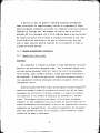
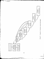
Software development process
.
.
.
.
.
.
.
.
.
.
.
49
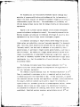
3Example of software system development
.
.
.
.
.
69
Software configuration control.. .
.
.
.48
.
2
.
LIST OF TABLES
page
Table 1
Software maintenance
.
..
.....
vii
.
.
.
.
58
V+
INTRODUCTION
This report is
the second of two documents prepared in
tht Air Force contract for the update of MIL-F-9490D,
tion for the design,
test and installation of flight
fulfillment of
the general specificacontrol systems for
piloted aircraft.
The objective of this contract
effort was to incorporate,
through
an amendment to the specification and supporting user information,
up-to-date
requirements and information necessary for more efficient system acquisition.
This report provides User Guide information and substantiating background
material in
support of the first
MIL-F-9490D is
in
1982.
However,
document,
Amendment 1 to MIL-F-9490D.
scheduled to be converted into MIL-Prime-SPEC format
results of a validation nrogram conducted under contract
by Northrop Corporation with Lockheed-Georgia Company as subcontractor and
the release of pertinent new data have indicated that an updated amendment
would aid in
the preparation of the revision and increase the usefulness of
the specification until
the new revision is
available.
I+•
SI
S.
...
"•M"
' :++
++• +'"]+<
'•+++......
,.+•+•
+i "'
,+•
",°!• `••. +.+
•,+•.+.=•++•+
'•+>++
+.+
...... ...--..•,++
.. ••++
+u: :. ++
+++.,
,.• ,+... ..+:+ ,.+.+ •]++• ,;++••+• •+ I
SCOPE
In this program,
only existing flight control system data was to be
Recommenda-
the substantiation of new specification requirements.
used in
tions and background information were to be based on existing data and
require no additional study and analysis programs.
Because of the short duration of the contract,
it
was necessary to
identify and limit the potential areas for revision or discussion early;
only areas of significant impact were to be considered.
The following is
a
of the areas identified in coordination with the Air Force Update Panel.
list
Digital flight controls requirements relative to redundancy manage-
a.
ment,
data transaission, microprocessor applications,
and
software
verification/validation.
b.
Fly-by-wire controls requirements relative to electrical design,
signal transmission,
actuation failure management,
and immunity
to associated subsystem failures.
c.
confidence
Self-test capability requirements versus complexity,
level, and preflight test duration.
d.
Cockpit controls/displays design requirements to accommodate high-g
cockpit geometry constraints and integrated displays.
e.
Actuation requirements to reflect the application of high performance
rotary mechanical actuators and electromechanical actuators to
essential or flight phase essential functions.
f.
Controls/structure interaction and integration requirements relative
to analysis and test verification.
g.
Simulation requirements relative to system development and performance verification as influenced by type of aircraft and flight
control system concept.
h.
Compatibility between the update amendment and the new revision of
the flying qualities specification, MIL-F-8785C.
Following a literature search and meetings with members of industry,
the
Subsequently,
the
resulting data were catalogued according to the key areas.
specifications and assimilated data were reviewed and recommended amendments
and discussions were prepared.
3
•i
,
I
SUM4MARY OF RESULTS
In
the preparation of this report it
became more apparent than ever that
flight control system design requires a multi-disciplinary approach incorporating various aspects of electrical and mechanical engineering and the system,
computer, and management sciences.
As a result there is a significant amount
of overlapping
and intertwining of various
requirement
The state of the art has advanced rapidly in
in
the area of electronics
to accommodate
the current
areas.
the last five years,
for digital flight controls.
particularly
This report attempts
state of the art while providing
for the implementation
of future advances.
The bulk of this report addresses the interrelated topics of digital
flight
controls, fly-by-wire controls, and self test and monitoring.
These topics
are addressed in many requirement areas.
In addition to being addressed in the
obvious areas of system test and monitoring and electrical signal computation
and transmission,
survivability,
they are also referred
invulnerability,
to in
and maintenance
the redundancy,
reliability,
requirements.
Of particular note are the additions of a redundancy management
and discussion,
which were absent
software requirements
in
the D revision,
requirement
and the integration of
for FCS design and documentation into the specification.
Where the D revision gave little
consideration
to FCS software,
this document
attempts to coordinate DOD software requirements and recommended approaches in
the specification and User Guide without restricting FCS software design.
Both
of these modifications
acquisition in
mind.
Other subjects
for stability,
displays,
In
have been made with the goal of more efficient system
covered in
this report include updates of the requirements
Automatic Flight Control Systems (AFCS),
and modification of
addition,
and cockpit controls/
the quality assurance and actuation
requirements.
an effort was male to make MIL-F-9490D compatible with the latest
revision of the specification for flying qualities of piloted airctaft,
MIL-F-8785C.
In
preparing the amendments for the AFCS and the cockpit controls/displays
requirements,
Volumes II
and III of AFFDL-TR-77-7,
the Northrop/Lockheed-Georgia
5
_____
__
-
__
__
__
_I.
____
_____
____
%
validation of MEL-F-9490D, were the main reference sources,
coupled with the
current experience of our advisory personnel.
Amendments t, the ruality assurance requirements provide a thorough and
comprehensive documentation of FCS design requirements,
documentation,
in
particular software
and test requirements relative to system development and
performance verification as influenced by aircraft type and FCS concept.
For some requirements there were no amendments.
However,
User Guide
discussions were expanded in an effort to incorporate recent experiences and
current thLnking.
In some cases,
such as stability margins and survivability,
the amendment modifies the emphasis of the requirement rather than making a
quantitative change.
monitoring,
In others,
such as reliability and system test and
amendments were felt to be either undesirable,
ity of the specification,
effort.
•',
or out of scope,
given the general-
given the size of the contract
APPENDIX .
Appendix in support of Amendment 1 to MIL-F-9490D and Background
Information and User Guide for MIL-F-9490D
I
7
2
TABLE OF CONTENTS
Page
2.
3.
APPLICABLE DOCUMENTS ..........
2.1
..........
2.2 Other publications .......
..................
..................
.................
..
.
REQUIREMENTS
......................
3.1.2 AFCS Performance requirements.
....
.......
..
3.1.2.2
Heading hold ........
.................
..
3.1.2.3 Heading select
. . ...............
3.1.2.4
Lateral acceleration and sideslip limits
.
3.1.2.4.1
Coordination in steady banked turns . ....
3.1.2.4.2
Lateral acceleration limits, rolling
....
3.1.2.4.3
Coordination in straight and level flight .
3.1.2.6
Mach hoJd .........
...................
...
3.1.2.7
Airspeed hold .......
.................
....
.............
.................
VOR capture and tracking ...
.........
TACAN capture and tracking ...
........
. ...
..
...
..
..
"*3.1.2.8 Automatic navigation
"*3.1.2.8.1 VOR/TACAN . ........
3
.1.z.8.1.1
3.1.2.8.1.2
3.1.2-8.1.3 Overstaticn ...................
Automatic instrument low approach system
3.1.2.9
3.1.2.9.1
Localizer mode ...... ..........
. .
3.1.2.9.2
Glide slope mode ......
..............
"*3.1.2.9.3 Go-around mode ......
...............
. .
.
.
.
.
..
15
15
15
17
17
17
18
18
19
19
20
20
i
22
22
23
23
24
24
24
26
27
3.1.2.9.3.2
Lateral-heading AFCS go-around performance
standards
..
.
. . . . . . . . . . .
..
"*3.1.2.9.3.3 Minimum go-around altitude ... ........
3.1.2.10 All weather-landing system . . ..........
3.1.2.101. All weather landing performance standards variations of aircraft
and airborne equipment
configurations ....
...........
. ..
3.1.2.10.2
Performance standards - ground based equipment
variations ........
................
..
*3.1.3.1 Redundancy ..........
..................
..
3.1,3.1.1
Redundancy management ....
............
..
3.1.3.3.4
Failure transients ....
.........
. . .
.
3.1.3.6.1
Stability margins . . . . . . . . . . . ...
3.1.3.6.2 Sensitivity analysis . . . ..........
3.1.3.7
Operation in turbulence ............
.
3.1.3.7.1
Random turbulence . . . . . . . . . . . . . .
and monitoring provisions ... .....
*3.1.3.9 System test
SDenotes
requirements -:hich are discussed,
changes are recommended.
9
27
27
28
29
30
30
31
36
37
37
40
41
41
but for which no
TABLE OF CONTENTS (continued)
Page
"3.1.6
"*3.1.7
Mission accomplishment reliability .. .......
... 46
Quantitative flight
safety .......
...........
*3.1.8 Survivability ............
..................
3.1.8.1
All engines out conttol .....
............
"*3.1.9.2 Invulnerability to lightning strikes and static
47
50
52
atmospheric electricity
. . . . . .......
Invulnerability to onboard failures of other
systems and equipment . . . . . . .......
3.1.9.5
Invulnerability to maintenance error
....
3.1.9.5.1
invulnerability to software maintenance
error . . . . . . . . . . . . . . . . . . . .
3.1.10 Maintenance provisions ..... ..............
.
3.1.10.2.1
Use of cockpit instrumentation .........
..
3.1.10.2.2.1
Provision for portable test
equipment
growth . . . . . . . . . . .........
3.1.10.2.2.2
Provision for portable test
equipment
software . . . . . . . . . . . . . . . . .
3.1.10.4
Maintenance personnel safety provisions
. . .
53
3.1.10.5
Software maintenance and verifiability
3.2.1
Pilot controls and displays ..................
3.2.1.1
Pilot controls for CTOL aircraft
. . .
3.2.1.1.5
Trim switches ..... ................
3.2.1.1.8 Normal disengagement means ...
.........
3.2.1.4.1
FCS annunciation ..... ..............
3.2.1.4.2.2
Failure status .......
..............
3.2.1.4.2.3
Control authority annunciation
. .
3.2.3.1
General requirements ....
..........
3.2.3.1.4
Rigging Provisionr
. . . . . . ........
3.2.3.2.4.1
Control Cable ..
..
..
..
..
..
57
58
59
59
60
60
60
61
61
61
61
3.1.9.4
3.2.3.2.4.12
Fairleads and rubbing strips .
3.2.3.3.1.2 Wire Terminations ..........
3.2.3.3.2
Multiplexing .......................
.
.
.
.
..
..
...
.
.
.
.
...
. .
. .
.
..
.
.
.
.
.
.
.
3.2.4.1.2
Interchangeablity .....
................
Electrical signal computation .........
3.2.4.3.1
Amalog computation .....
.............
3.2.4.3.2
Digital computation ................
*3.2.4.3.2.1 Memory protection .....
.............
*3.2.4.3.2.2 Program scaling ..............
*3.2.4.3
3.2.4.3.2.3
3.2.4.3.3
Software support .......
...
.
...
............
...
54
55
55
55
56
57
57
57
62
62
62
63
63
64
65
66
66
67
Computational input/output gtowth
capability
.
.
.
..........
.
.
68
*3.2.6 Actuation ........
....................
3.2.7.3.2
Microelectronics
.....
.................
3.2.7.3.3
BL n-in . ...................
68
70
70
• revotes requirements which are discussed, but for which
changes are recommended.
11
ffiMECEIN~G
__________i__
I
.
-,-F
..
PAGE B LK..NqX-J'
lLL
TABLE OF CONTENTS (continued)
Page
4.
QUALITY ASSURANCE ......................
4.1.1
Methods for demonstration of compliance
4.1.1.1
4.1.1.2
Analysis . . . ...........
Inspection ..... ..................
4.1.1.3 Test . . .............
4.2 Analysis requirements
. . . .
.
.
.
Functional mockup and simulator tests
.
.
.
.
.
.
FCS analysis report
FCS test
report
.
NOTES ....
.....
6.6 Definitions
.....................
. . . . .
73
74
.
.
.
Flight control system development plan ........
.
71
72
72
73
......
4.4.1
.
71
.
Aircraft ground tests
.
71
.
....
4.3.3
.
.
...
Component tests
.
.
................
4.3.2.2
.
.
.........
4.3.2,1
4.4.3.1
4.4.4.3
6.
.
.
.
4.2.1 Piloted simulations ..... ...........
4.3.1.2 Acceptance tests ........
...
.
.
75
...
.
.
.
.
.
.
.
.
.
.
.
.
.
.
.
.
.......
.
.
.
.
.
.
.
.
.
75
...
.
.
.
77
78
78
.
.
75
.
.
.
80
80
F!
~
13
-
-i
E~C~~GpAMg BLAL4K-NOT F1ýL~D
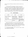
2.
APPLICABLE DOCUMENTS
2.1:
Toggle,
Under line 9,
"MIL-F-3541",
insert "MIL-S-3950 Switches,
Environmentally Sealed, General Specification for".
Under line 34,
Sensitive and Push,
"MIL-G-6641",
insert "HIL-S-6743 Switches,
Snap Action, Actuators and Enclosures, General Specifica-
tion for".
Under line 91,
"HIL-M-38510",
insert "MIL-S-52779 Software
Quality Assurance Requirements" and "MIL-C-81774 Control Panel, Aircraft,
General Requirement for".
Under line 103,
"the Selection of",
insert "MIL-STD-203
Aircrew Station Controls and Displays for Fixed Wing Aircraft".
Under line 111,
"ments for Equipment" insert '"MIL-STD-471A
Maintainability Verification/Demonstration/Evaluation".
Under line 113,
"and Waivers" insert "MIL-STD-483 Configura-
tion Management Practices for Systems, Equipment,
Munitions and Computer
Programs" and "HIL-STD-490 Specification Practices" and "MIL-STD-499 Engineering Management".
Under line 119,
"Equipment and Facilities" insert '"MIL-STD-
1521 Technical Reviews and Audits for Systems,
Equipment,
and Computer
Programs".
Under line 115,
"of",
insert "MIL-STD-781 Reliability Design
Qualification and Production Acceptance Tests:
Under line 147,
Exponential DistributioL".
"AFSC DH 2-2" insert the following heading
and publication title:
"Air Force Regulations Document
AFR-800-14
Vol.
I:
Vol.II:
Management of Computer Resources in Systems
Acquisition and Support Procedures for Computer
Resources in Systems".
2.2 Other publications.
Line 20:
Change the heading to "FAA Advisory
Circulars".
I
15
A____
~P.ECEII~I
Z~J--Fl
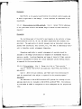
Discussion
The applications of the documents which have been added to this section
are addressed
of sections 3.
in
the discussiGns of the appropriate
and 4.
and addidion of definitions in
16.
..........................
16
amended requirements
Para.
6.6.
3.
REQUIREMENTS
3.1.2
AFCS performance requirements.
Line 1: Before the first sentence
insert "Engage and disengage, selection logic, and functional safety criteria
and limits for each AFCS function shall, be established and specified in the
detail flight control specification."
Discussion
The intent of this amendment is to highlight the need for AFCS requirements to be tailored to each particular procurement activity, thereby allowing
flexibility and freedom in AFCS design.
3.1.2.2
Heading hold.
Line 4:
"When heading hold is engaged,
Delete the last sentence and substitute
the aircrdft shall roll towards wings level.
The reference heading shall be that heading that exists when the aircraft
passes through a roll attitude that is wings level plus or minus a tolerance."
Discussion
It may be arguable that a heading hold accuracy of 4-0.5 degrees does not
appreciably enhance mission effectiveness or aircraft operational efficiency
over an accuracy of +1.0 degree for the heading hold mode.
Since, however,
the state-of-the art now allows realization of the more stringent requirement
without undue penalty in cost, the requirement is considered valid.
The 5 degree RMS heading deviation requirement for operation in light
tur'ulence is desirable.
This prevents design of an easily saturable mode
while not restricting the functional design of the overall AFCS,
reference 1.
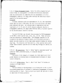
If a flight controller is used, when the controller is returned to detent,
the aircraft shall roll towards wings level; the reference heading shall be
that heading that exis's when the aircraft passes through a roll attitude
that is wings level plus or minus a tolerance.
17
-
..
The .equirement
the controller is
?-his confusing.
states that heading hold shall automatically engage as
returned to the detent.
The woid "when" is
The use of the word "as" makes
proper In this case.
A majority of the
aircraft use the detent position as the logic for going to the heading hold
mode,
reference 1.
For initial engagement of heading hold,
hold from control stick (wheel)
angle,
or subsequent return to heading
steering or flight controller commanded bank
the selection of the reference heading is
not made until two criteria
are satisfied:
1) heading hold is selected,
2)
and
the roll attitude is approximately wings level.
This dual criterion ensures that the aircraft will not be forced to make
an appreciable turn in the opposite direction in order to capture a heading
that existed while the aircraft was in a turn and heading hold was engaged.
3.1.2.3
Heading select.
Line 7:
After the fourth sentence,
insert "Entry
into and exit from the turn shall be smooth and rapid."
Discussion
The imposition of limits on roll rate and roll acceleration when maneuvering
to the new heading establishes an upper limit for the rates and accelerations
but does not address a minimum accepLable.
The requirement for smooth and
rapid assures that minimum rates, as well as maximum, will be acceptable.
The roll rate and acceleration upper limits are specified to preclude
an overly rapid response.
roll-out of the turn is
sluggish,
3.1.2.4
The requirement for smooth and rapid roll-in and
stated to ensure that the response is
not unduly
reference 1.
Lateral acceleration and sideslip limits.
Line 1:
Delete the first
sentence and substitute "Except for flight phases using direct side force
control or during which sideslip is
deliberstely induced,
e.g.,
forward slip
18
a____
____
____
- ___
___
____
___
____
___
___i.
___
____
___
____
I
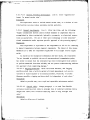
to a landing, the following performance shall be provided when "ny lateraldirectional AFCS function is engaged."
Discussion
Deliberately induced sideslip maneuvers,
such as those which might be
used during coupled autoland modes, are excluded from this requirement.
The acceleration and sideslip limits as previously defined di! not account
for deliberate sideslip maneuvers.
Autoland implementations and the advent
of control-configured vehicles require that these limits not be applied during
deliberate side-slip or side-force maneuvers.
3.1.2.4.1
Coordination in steady banked turns.
Line 1:
Delete the first
sentence and substitute "The incremental sideslip angle sha.ll not exceed
2 degrees from the trimmed value, and lateral acceleration shall not exceed
0.03g while at steady bank angles up to the maneuver bank angle 11mit reached
during normal maneuvers with the AFCS engaged."
3.1.2.4.2
Lateral acceleration limits, ro.iling.
Line 2:
Delete "aircraft
with" and substitute "flight condition with aircraft".
line 3: Delete "aircraft with" and substitute "flight
condition with aircraft".
line 4: DeleLe "aircraft with" and st :,•,itute "flight
condition with aircraft".
Discussion
This change recognizes that an aircraft's roll rate capability will vary
within the aircraft's flight envelope and as roll rate capability varies so
will the required lateral acceleration limits. For example, *f an aircraft
with a 90 deg/sec maximum roll rate capability can only roll at 30 deg/sec in
some portion of the envelope, then at that condition, the tolerance cIould be
+O.Ig not +0.5g.
19
I,
straight and level flight.
Coordination in
3.1.2.4.3
Line 1:
Delete the
first sentence and substitute "The accuracy while the aircraft is
in straight
arid level flight shall be maintained with an incremental sideslip angle of
+1 degree from the trimmed value or a lateral acceleration of +0.02g at the
c.g.,
whichever is
lower."
Discussion
in order to account for steady-Gtate trimmed sideslip angles which are
required to support vehicle and store asymmetries,
the requirement has been
changed from absolute to incremental values of sideslip and lateral acceleration.
Vehicle asymmetries,
especially those caused by asymmetric stores,
will
require a steady-state sideglip angle to balance the unsymmetrical aerodynamic
forces.
Non-zero bank angles may also be required to support steady-state
Under these conditions it
trim.
is
necessary to replace the absolute sideslip
angle restriction with incremental sideslip from unaccelerated flight reference
sideslip values.
3.1.2.6
Mach hold.
Line 1:
Before the first sentence,
quirements of this paragraph shall be wiet in
insert "The re-
straight, steady flight including
climb or descent."
Line 7:
After the last sentence,
add "Adjustment
capability of at least +0.01 Ma'zh shall be available to allow the pilot to
vary the reference Mach number around the engaged Mach number."
Discussion
This requirement is
applicable to a Mach hold moae using either the
autopilot pitch axis or an automatic throttle system.
specification should define which is
to be used.
automatic throttle systems on the QB-47,
e
adjustment capability must
C-141,
The RFP and the FCS
Experience on installing
and C-pA has shown that some
e made available for the pilot.
20
I
It
in
very difficult to engage the mode at the control airspeed reauired
is
ARINC Characteristic No.
adverse weather.
558 (Air Transport Automatic
Throttle System) indicates a full range of adjustment for their system,
reference 1.
The basic purpose of the Mach hold mode is
capability in
to provide a Mach hold
"straight and level" cruise flight where optimum range or time
will result, or in climb out where the best rate or angle of climb Mach will
be maintained.
The requirement is applicable to a Mach hold mode using
either the autopilot pitch axis or an automatic throttle system.
possible two-degrees-of-freedom control,
e.g.,
modes,
This makes
simultaneously selecting two control
altitude control through pitch and Mach through autothrottle.
This enables Mach hold to be engaged during maneuvering flight where the
system is unable to control Mach within the requirements,
or under conditions
where the system is
able to control Mach but at the expense of altitude.
For example,
"stem which controls Mach by pitch,
for
requires a descirt in
order to maintain Mach,
if
a Mach upset
an ever increasing rate of
descent will occur as the aircraft descends to lower altitude.
is
The pilot
responsible for maintaining safe flight under these or similar conditions.
3.1.2.7
Airspeed hola.
Line 1:
Before the first
insert "The
sentence,
requirements of this paragraph shall be met in straight,
steady flight
Including climb or descent."
Line 6:
After the last sentence,
add "Adjustment
capability of at least +10 knots shall be available to allow the pilot to
vary the reference airspeed around the engaged airspeed."
Discussion
This requirement is
applicable to an airspeed hold mode using either the
autopilot pitch axis or an automatic throttle system.
specification should define which is
to be used.
automatic throttle systems on the QB-47,
C-141,
The RFP and the FCS
Experience on installing
and C-5A has shown that some
adjustment capability must be available for the pilot.
It
is
very difficult
to engage the mode at the control airspeed required in adverse weather.
21
ARINC Characteristic No.
558 (Air Transport Automatic Throttle System) Indi-
cates a full range of adjustment for their system, reference 1.
3.1.2.8
A
Automatic navigation
Discussion
This paragraph covers only general requirements for VOR and TACAN
navigation modes and definition of terms.
Specific requirements for inertial navigation, area navigation, or
vertical navigation control are not included in this specification since
these requirements will depend on the aircraft mission. Normally these
requirements will be included in the procurement detailed specification, when
such functions are required.
Requirements for a microwave landing system (MLS) approach mode have not
been included at this time because of the lack of definitive information
on MLS ground facilities and contingent approach procedures.
VOR/TACAN
3.1.2.8.1
h
Discussion
The VOR and TACAN overehoot and tracking accuracy requirements are
stated in
terms of angular error with respect to the selected radial.
Thus
the allowable error automatically decreases with decreasing distance to the
station.
The TACAN requirements are more stringent than those for VOR,
reflecting the improved performance that should be achieved through use of the
TACAN range information.
The tracking accuracy requirements are stated in
terms of RMS errors over a defined distance from the station that is far
enough removed to be out of the geometric sensitive area.
All distances are
given in terms of nautical miles to be compatible with Air Traffic Control
data format. The overstation requirements allow for resetting the capture
logic if it
is found to be desirable by the contractor.
22
" -
•
|
I..
.
.
.
-"
.
-. ,
N.
3.1.2.8.1.1
VOR capture and tracking.
Delete the entire paragraph and
substitute the followingt
"Overshoot shall not exceed 1-1/3 degrees (20pa)
beyond the desired VOR
radial beam center in a no-wind condition for captures 50 nautical miles or
more from the station with intercept angles up to 45 degrees.
capture at 50 nautical miles or more,
root-mean-square (RMS)
Following
the aircraft shall remain within a
1-1/3 degrees (20
p a)
from the VOR radial beam center.
RMS tracking error shall be mdeasured over a 5 minute period between 50 and 10
nautical miles from the station or averaged aver the nominal aircraft flight
time between the same distance limits, whichever time is
shorter."
Discussion
The use of the term "average error" is
objectionable since large
"hunting" errors could occur to right and left of the beam and still
in a small "average" error, reference 1.
3.1.2.8.1.2
TACAN capture and tracking.
result
Delete the entire paragraph and
substitute the following:
"Overshoot shall not exceed 0.5 degrees beyond the desired TACAN radial
beam cencer in a no-wind condition for captures 100 nautical miles or more
from the station with intercept angles up to 45 degrees.
100 nautical miles or more,
square (RMS)
Following capture at
the aircraft shall remain within a root-mean-
0.5 degrees from the TACAN radial beam center.
RMS tracking
error shall be measured over a 10 minute period between 100 and 10 nautical
miles from the station or averaged over the nominal aircraft flight time
between the same distance limits, whichever time is
shorter.
The required 0.3
damping ratio shall be exhibited for continuous tracking between 100 and 10
nautical miles from the station."
Discussion
The TACAN capture and tracking requirements were translated to angular
measure and the required tracking accuracy defined.
23
The requirement,
as
-
7-
compared with VOR tracking accuracy requirewents,
reflects the improved
accuracy that can be achieved through use of the range information.
3.1.2.8.1.3
Overstation.
Line 3:
the period and insert "in
At the end of the first sentence,
remove
a no-wind condition."
Discussion
The overstation mode requirements for VOR and TACAN defined in
paragraph include provisions for resetting the beam capture logic.
this
One of
the more common complaints from military and commercial pilots relates to
limited capture performance for the outbound radial.
Generally these com--
plaints have occurred because the AFCS remains in a tracking mode during
station overflight.
Consequently,
limited bank angles,
etc.,
outbound captures are hampered by extremely
designed to ensure good tracking performance.
Future configurations should provide for more favorable outbound capture
performance by development of more comprehensive control laws or providing
capture logic reset as a function of station overflight.
3.1.2.9
title
Automatic instrument low approach sstem.
Line 1:
Change
the
to "Automatic approach system (ILS)."
Discussion
This change denotes that the 3.1.2.9 subparagrapns are applicable to
only ILS systems.
3.1.2.9.1
Localizer mode.
Delete the entire paragraph and substitute the
following:
"The AFCS shall maintain a constant heading until the aircraft is
+150 microamperes of the beam center,
within
at which point the aircraft will be
maneuvered to capture the localizer beam.
Heading or roll rate and attitude
commands shall be limited to provide a smooth capture and subsequent tracking
of the localizer beam.
The initial overshoot during capture shall not
24
exceed 75 microamperes and the system shall exhibit a damping ratio of at
least 0.1 with interceot angles of 45 degrees at 8 miles frow runway threshold
•
3
and increasing linearly to 60 degrees at 18 miles from runway threshold in a
no-wind condilion.
For intercept angles less than 45 degrees,
always maneuver the aircraft toward the course centerline.
movement away from the runway threshold during capture.
considered to be in
satisfied:
rate is
the FCS shall
There shall be no
The system shall be
the tracking mode whenever the following conditions are
Localizer beam error is
0.025deg/sec
(2j.a/sec)
1 degree (75pa)
or less.
or less,
localizer beam
During beam tracking the system
shall exhibit a damping ratio of 0.2 or greater.
From the outer marker to
an altitude of 300 feet above runway elevation on the approach path,
the AFCS
shall maintain the aircraft 2-sigma position within 0.47 degrees (35pa)
the localizer beam center.
of
On the approach path from 300 feet above
runway elevjation to the decision altitude of 100 feet,
the aircraft 2 sigma position within 0.33 degrees (
25
the AFCS shall maintain
pa).
The performance
during the tracking mode shall be free of sustained oscillations.
criteria shall be based on a Category II
These
localizer ground installation."
Discussion
It
is
felt that the requirements of this paragraph are too stringent and
do not provide m1ximum designer freedom while retaining required flight safety.
The overshoot requirement of 0.5 degrees (37.5 microamperes)
is
very tight and could require a special design such as a variable gain
system for a requirement that is
capture is
is
radial error
The point at which the beam
not critical.
initiated should be specified.
the best point to start beam capture.
It
is
felt that 150 microamperes
This requirement states that a
damping ratio of 0.2 or greater shall be exhibited during the tracking mode at
a distance of 40,000 feet from the transmitter.
This does not give the
required damping before and after the 40,000 foot point.
should be required throughout the tracking mode.
the requirement is
The tracking accuracy of
more stringent than the FAA Category II
quirement of Advicory Circular AC 120-29.
It
is
This damping ratio
approach re-
felt that the FAA requirements
should be used since these requirements are considered applicable to military
aircraft,
reference
1.
25
3.1.2.9.2
Glide slope mode.
Line 7:
After "satisfied" insert "the first".
Line 5:
Delete "from below the beam in level flight at an
altitude greater than 800 feet above the glide slope transmitter datum
altitude in a no-wind condition." and substitute "in a no-wind condition from
above or below the beam under normal approach configurations,"
Line 9:
Delete "0.085" and substitute "0.20".
Line 10: Delete "for the conditions defined." and substitute
"and the transient errors encountered during the tracking mode shall not
exceed 0.16 degrees (35•a) of radial error from glide slope beam center."
Liue 10: Delete "Or" and substitute 'Nhen using".
Line _11:
in ICAO Annex 10".
Line 13:
Delete "(including 10,000 foot runway) as defined
Delete "opposition" and substitute "position".
Discuss'on
It is felt that this is a good requirement,
but some changes are required.
Capture performance requirements are only given for captures from below
the beam.
At the present time, more and more approaches are being made at a
steeper angle due to environmental (noise) considerations; therefore,
the
performance requirements for capture should be given for above and below the
beam.
This requirement also limits the capture performance requirements to
an altitude greater than 800 feet above the glideslope transmitter datum
altitude.
The capture requirements should be met at any point of capture.
The damping ratio requirement of 0.085 or greater after the first overshoot is not acceptable.
A damping ratio this low would be just as bad as
neutral stability and could induce PIO (pilot induced oscillation).
The damp-
ing ratio after the first overshoot should be similar to the localizer mode.
The transient error that could occur during beam tracking should be
The transient error should never exceed the
covered in this requirement.
error allwed for the first overshoot.
26
' • • ' . . ". . . ...•
. . ., . .: . . . • o•
. .. •.....•
".. ..
-,,.,' ..,
.. •
The 2-sigma tracking requirements of 0.16 degrees (351ta)
feet of beam center are felt to be reasonable.
or within 12
This tracking accuracy is
the
some as that required in Advisory Circular AC 120-29.
3.1.2.9.3
Go-around mode
Discussion
The use of an automatic go-around mode would depend on the aircraft and
mission requirements.
If such a mode is required then this requirement, with
the provision that autopilot steering commands are displayed on the flight
director, would be relevant for present and future aircraft.
3.1.2.9.3.2
Lateral-heading AFCS go-around performance standards.
Line 3: After "planes" insert "defined in FAA Advisory
Circular 120-29%.
Discussion
This requirement is valid for present and future aircraft with a change.
The first sentence should be changed to include reference to the FAA Advisory
Circular 120-29 which is implied.
It should be noted that the performance
requirement of the last sentence is completely dependent on pilot reaction
and performance and is not an operational performance requirement on the
AFCS.
It does affect the system design ji the autoi'atic go-around mode
in the area of failure announcement and affect of failures or disengagement
1
of the mode on the aircraft flight path. No change is suggested in this area.
3.1.2.9.3.3
Minimum go-around altitude
Discussion
The requiremeit is valid for present and future aircraft with the
understanding that it assumes that all aircraft will require a minimum altitude for engaging the go-around mode.
The C-5A and C-141 flight testing has
shown that minimum altitude for these aircraft is the runway altitude. 1
27
11
3.1.2.10
All weather landing system.
Line 1:
Change the title
to "Automatic
landing system."
Line 1:
Delete "all weather" and substitute "automatic".
Line 4:
Delete the second sentence and substitute "Automatic
landing system shall be designed to be compatible to operations in C-tegory
III weather minimums and comply with the following landing accuracies and
operational requirements:"
Line 15:
Delete "(normally used during ICAO Category IlIb or
IIlc visibility conditions)".
After line 24,
"d.
add the following paragraphs:
Automatic landing system malfunction should not cause significant dis-
placement of the aircraft from its approach path,
including altitude loss, or
cause any action of the flight cuntrol system that is
not readily apparent to
the pilot, either by control movement or advisory display.
connection,
Upon system dis-
the automatic landing system shall not cause any out-of-trim
condition not easily controlled by the pilot.
e.
Means should be provided to inform the pilot continuously of the mode of
operation of the automatic landing system.
Indication of system malfunction
should be conspicuous and unmistakable.
Positive indication should be provided
that the flare has been initiated at the minimum normal flare engage heights.
f.
The automatic landing system design shall meet the criteria for approval
of Category III landing weathe
minimums defined in
paragraph 6.6."
Discussion
An automatic landing system (ALS)
includes specifically all the ele-
ments of airborne equipment and more generally includes the ground-base.d
equipment ne essary for completion of an all-weather landing.
All-weather
landings comprise the operations and procedures required to conduct approaches
and landings during Category II
and III visibility conditions defined by the
International Civil Aviation Organization.
28
S,
.
. ...
This definition states that an ALS Includes all aircraft equipment,
ground based equipment, operations, and procedures over some of which the
contractor has no authority or control.
Since this specification is intended
to cover the design, installation, and test of flight control systems byI
establishing general performance, design, development, and quality assurance
requirements for the flight control systems, the requirement for an automatic
landing system as defined is believed to be beyond the scope of this specifi-I
cation.
The majo.Aty of the performance requirements stated in the require--
ments however are pertinent to an automatic landing mode.
It is recognizedI
that the procuring agency has the need to exercise its prerogatives for
ground and flight procedures and equipment and for weather minimums for which
the aircraft should be cleared.
The contractor must satisfy the requirements
insofar as he is able within the limitations imposed by requirements and1
equipment over which he has no control. The contractor shoutld therefore be
responsible for installing equipment to meet specific performance requirements
which are measurable and for which he has control.
Requirement 3.1.2.10b implies that rollout guidance should be designed to
accommodate Category 1M~b and ITIc visibility conditions.
This requirement
could require sophisticated ground equipment to be installed at the landingi
area.
The type of ground guidance used would dictate the equipment to beI
installed in the aircraft.
It is felt that this is not feasible since each
government organization, aircraft manufacturer, equipment manufacturer, and
related organization would have different approaches on proper ground guidance
to achieve Category tl~b and IlIc control.
In addition) it is believed
that there are no commercial or military airfields that have ground equipment that is capable of' guiding an aircraft under the stated weather minima.
This requirement should require equipment installed which could be
used in meeting the Category IlIa Landing Weather Minima.
Any furtherI
requirements beyond Category IlIa should be contained in the RFP with an
explanation of the ground equipment to be used.
3.1.2.10.1
All weather landing performance standards
and airborne equipment configurations.
29
Line 1:
-
variations of aircraft
Change the title to "Auto-
matic landing performance standards
-variations
of aircraft and airborne
equipment configurations."
Discussion
This requirement is valid for present and future aircraft except for the
title "All weather landing system."
landing system,"
This should be changed to "Automatic
See the evaluation on requirement 3.1.2.10,1
3.1.2.10.2 Performance standards - ground based equipment variations.
the entire paragraph and substitute the following:
DeleteI
"Proof of compliance with performance requirements for automatic landing
systems shall include the effects of expected variation in type and quality
of the ground based equipment."'
Discussion
This requirement includes areas that should not be included in a flight
control system specification, such as touchdown zone lighting and taxi zones.
only flight control requirements that the aircraft manufacturer is responsible
for should be included in this specification to insure that compliance with
requirements can be demonstrated.
This same subject is discussed in the
evaluation of requirement 3.1.2. 10.
This requirement should include the expected variatiouI Of the ILS beam
that should be considered during design and evaluation.
3.1.3.1
Redundancy
Discussion
In support of the redundancy discussion in the User Guide, formal definitions of the terms fail operate, fail passive and fail safe have been
included as ai, update to the Definitions paragraph 6.6.
In a discussion of the survivability requirements of 3.1.8, the topic
of dissimilar back-up systems is reviewed.
30
C
-'!lu
3.1.3.1:
After this paragraph,
"3.1.3.1.1
insert the following as a new paragraph:
Redundancy management.
In the design of a redundant flight con-
trol system, the redundancy management approach determined by the contractor shall be:
a. based on meeting the flight safety and mission reliability requirements of this specification.
b.
consistent with the use of the system test and monitoring provi-
sions of requirements 3.1.3.9 and associated subparagraphs.
F.
c.
validated by appropriate analyses.
d.
addressed in the software requirements definition when applicable."
Discussion
With the utilization of redundant channels for the implementation of
active control technology in present and future al.rcraft, redundancy management has become a major flight control system design erea,
be addressed by this specification.
tion is
and thus needs to
Without this requirement the specifica-
deficient.
As shown in references 2 through 14,
numerous flight control system speci-
fications and studies addressing the implementation of fly-by-wire control
sysLems have tmajor sections addressing redundancy management.
Currently the
F-18A uses an estimated minimum of 25% of its
software for redundancy manage-
ment.
The purpose of redundancy management is
protection and efficienL,
to provide failure transient
effective normal operation, while maximizing mis-
sion reliability and flight safety.
To this end, redundancy management must be employed at various levels
within the flight control system architecture to perform such tasks as:
I) failure detection
2)
failure isolation
3)
system reconfigtration
4)
5)
channel recovery update
cross channel data transmission
6)
cross channel synchronization for synchronous computers
7)
input signal management
8)
actuator management.
In performing these tasks, in particular failure detection and isolation, the redundancy management approach will influence and be influenced by
31
the 3.1.3.9 specification requirement and the inflight monitoring techniques
discussed in
this document and the MIL-F-9490D User Guide.
The comprehen-
siveness of any redundancy management approach will be based on its utilization o0 voter planes and inline (or self test) monitoring.
It has been
shown that for long missions, systems employing interunit selection at Lhe
LRU level can be more reliable than systems employing one higher level of
redundancy and using midvalue signal voting as the o:ly means of fault
detection and isolation.
Thus application of advanced redundancy management
requirement can result ia significant
techniques to meet a given reliability
equipment savings
.
Some caveats for redundancy management are: i)
for
electrical signal computation no computer shall interfere with the operation
of another,
and 2) pilot intervention should not be required for system
reconfiguration in
the event of a failure.
In the implementation of redundancy and redundancy management methods to
satisfy flight safety and mission reliability requirements,
that the design address not only what is
system per se, but also what is
it
is necessary
required for the flight control
required for any supporting system (e.g.,
mission computer and air data system) which is
flight safety critical or
flight phase essential.
The success criterion by which a redundancy management approach is typically measured is
its coverage.
Although the term coverage has been given
slightly dkifferent interpretations
in
the literature
av.ailable today,
the most
ei~copassing one defines coverage as the conditional probability that, gi in a
failure,
-he system continues to perform the required function.
While some studies,
references 7, 9,
and 11, have specified that a
probability tf coverage as high as 1.0 can be obtained for a first
failure
and a probability of .94 or better for a second failure in order to achieve
an Ecceptable flight safety value, in practice attempts to achieve the
required flight safety goal typically utilize lower failure coverages,
references 2, 4, 5, 6, and 15.
The critical criteria for the determination of acceptable probability of
coverage values for first
and second failures are the mission reliability
flight safety requirements of paragraphs 3.1.6 and 3.1.7.
and
When assured
adequate reliability and safety other influencing factors are the tradeoffs
between system complexity,
weight and cost.
32
i4.
In the development of redundant flight control systems to satisfy the
flight safety requirements,
there have been as many different approaches as
there have been types of aircraft.
The DIGITAC aircraft,
references 5 and 6,
is
a modified A-7D containing dual digital computers,
designed to be fail safe for all failures and fail
eperation/fail safe for failures in the computer and memory units.
The
fail operation/fail safe capability of the dual computers and memories was
achieved by extensive self test; and the fail safe function of the servos
and sensors was made possible by comparison monitoring of dual servos and
sensors for all flight critical parameters.
Through computer monitoring,
the
interfacing units were fail safe.
Development p-oblems uncovered by this program are contributing to future
;
designs.
One example is
the problem of interaction between self-test routines.
In one instance, a power-supply problem caused one computer to fail. An
unforeseen timing situation in the self-test of the cross-computer data link
caused the good computer to shut itself off.
This problem was corrected.
However, its existence shows that these kinds of interactions must be studied
very carefully.
9
The F-8 Digital Fly-by-Wire system has three primary digital channels.
There is a back up system which is also electronic4, The critical input sensors
are triplex, and data from each of the redundant sensors are supplied to all
Identical signal-selection programs are performed in each
three computers.
E•
computer.
This signal selection i~ent~fies and removes
the effects of failed
sensors and produces identical input signals for each of the three computers.
These identical inputs are used by the computers to produce three control-surface
The midvalue of the three commands is selected by three
command outputs.
different servo-conLrol-elactronics channels.
These three channels drive the
three sections of triplex force-summed secondary actuators which in turn
The selection logic in the analog drive
command the primary power actuators.
channels will identify and eliminate a failed digital channel if its commend
signals deviate significantly
from the other two.
operating using the two remaining good channels.
The system will continue
Many of the faults detected
are transient and the system has the capability of restarting the failed
If the fault is
channel and returning to full three-channel operbtion.
permanent so that only two channels remain and they do not agree, the system
33
-
_______________________________________._
reverts to a triplex direct analog coupling between the pilot commands and
the servo drives.
The YC-14 system uses a triple-redundant set of electronics and multiple
aerodynamic surfaces to achieve fail operational/fail safe performance.6
The system provides automatic signal selection, failure detection, failure
isolation, failure warning, and failure isolation confirmation during flightcritical operations.
The input signal selection guarantees that all computers
will use the same numbers and thus produce identical outputs.
selected as the midvalue of the three values.
The output is
The system continues to
operate after the first failure by taking the average of the two rumaininig
systems.
When the two remaining systems disagree,
the aircraft is
they are both disabled and
flown manually.
For the quadruplex analog flight control system of the F-16,
failure
detection and isolation performed by inflight monitoring consist primarily of:
a)
middle-value signal selection following electrical signal computation
and FCC servo amplifier failure detection, and
b)
integrated servo actuator
(ISA)
failure detection.
The ISA failure detection incorporates differential Ire3sure sensing of
the servovalves,
hydromechanical
ai1lure detection, and TSA position versus
computer model position.
The F-16 is
fail operate if
no less than one fail operaite overall and a minimum of two
one failure is
electrical.
The F/A-18A flight control svnt:emn utilizes quadruplex digital computation,
direct elec't,.ical link,,t,
and a mechanical
The leading aLid trailing edge fl;qi.,
redundant servovalvep.,
electaca± capability.
bac, -up system in
pl '(h and roll.
and horizuotal/rolling tall.
have quad-
and t:hu: rudders and aileron surfacos have a dual/dual
All actuators have access to two separ;tiL
hydraulic
4ys tams •
The digital flight control, computers and the electrical system overall
have a two fail operate capabi.lity.
Hydromechanically the system has at least
a fail operate capability.
For the performance of redundancy management the F/A-lB inflight monitoring
is
very comprehensive.
In addition to thorough computer self-test the system
Through a cross channel data link the first evaluates
has two voting planes.
the input signals to the flight control computers, where failed signals are
ignored and the remaining good signals are averaged.
34
The second conceptual voting plane pertains to the actuator quad coil
drive current summing concept.
ator signals,
To evaluate the status of actuators and actu-
the redundancy management employs: differential pressure sensing
to evaluate the EHV; cross CAS monitoring to evaluate CAS ram, main ram,
and
input signals; and a current monitor to check servoamplifiers and EHV coils.
The current redundancy approach for the Advanced Fighter Technology
flight control system which provides a dual fail operate capability.
following excerpts,
taken from reference 2,
The
are an overview of the preliminary
AFTI-F-16 redundancy management*
Previous system architectural studies have indicated that optimum failure
survivability and failure isolation to the LRU level require that the flight
control system have three voting/monitoring planes. Two of these planes are
in software and are at the sensor/controller interface and the output surface
The purpose of the input/monitoring plane is to detect
command interface.
and isolate failures associated with the sensors, controllers, and input
circuitry from those associated with the processor and its memory.
The
output voting/ monitoring plane is used to detect and isolate failures
associated with the Flight Control Computer CPU and its memory.
It
is
located internally to the ISA's and can be used to isolate failures associated with the computer output circuitry and ISA servovalve coils, as well
as internal ISA failures.
In addition to these voting planes there is also processor self-test
which is used to isolate certain first failures and majority of second
like-failures.
the watchdog timer, word
Hardware self-test features (e.g.,
count and parity checks on MUX bus receipts,
memory parity and wraparounds)
Software driven self-
are always active and are used for failure isolation.
tests include memory-sum checks,
in backgrouLid,
which are accomplished
and
event-driven tests, which are activated when failures are discovereu.
if isolated by self-test, will cause
A second like processor failure,
control shift to the last remaining good processor.
isolated,
If
the failure is
not
then for AFTI-F-16 development safety purposes the independent
backup unit (IBU)
two fail operate capability is
engaged.
The IBU is
also
automatically engaged whenever all three processors indicate that they have
failed.
35
I
I
rI
In the AFTI program the projected coverage of a flight control computer
to isolate its own failure through self test is 0.95l6
3.1.3.3.4 Failure transients.
Line 3:
Delete the second sentence and
substitute "A realistic time delay between the failure and initiation of
pilot corrective action shall be incorporated when determining compliance.
This time delay should include an interval between the occurrence of the
failure and the occurrence of a cue such as acceleration, rate, displacement,
or sound that will definitely indicate to the pilot that a failure has
occurred, plus an additional interval which represents the time required for
the pilot to diagnose the situation and initiate corr',.ctive action."
Line 5:
Delete the third and fourth sentences and substitute
"The following limits apply to transients due to failures within the FCS as
a function of the Operational State of the system after the failure:
Operational
+ 0.5g incremental normal or lateral acceleration at
State I or II
(after failure)
the pilot's station and +10 degrees per second roll
rate, except that neither stall angle of attack nor
structural limits shall be exceeded.
In addition for
Category A, vertical or lateral excursions of 5 feet,
+ 2 degrees bank angle.
Operational
No dangerous attitude or structural limit is reached,
State III
and no dangerous alteration of the flight path results
(after failure)
from which recovery is impossible."
Discussion
Both 8785 and 9490 MIL specs cover the transient response following a
failure and pilot corrective action.
This duplication of coverage is sup-
ported because of the essential involvement of these two disciplines in~ this
very important issue.
Because of this duplication, however, it is important
to correlate the requirements as closely as possible to minimize the analysis
and tests necessary to demonstrate compliance.
36I
r
--- --------
-.
8785 discusses transients due to failures in two locations.
-.
~
jr"
Y
In the "Miscell-
aneous Flying Qualities" section (paragraph 3.4.8 i~n 87850), the considerations
by which one determines the pilot reaction time delay are given. Specific
numbers are not given, but rather guidance is given for each specific aircraft
and its warning system and natural cues.
consideration in 9490.
These are the same factors for
Transients due to failures are also discussed in the
"Characteristics of the Primary Flight Control System" section (paragraph
3,5.5.1 of 87850).
This is where load factor, roll rate, etc. response limits
are stated.
The objective in both specifications is to assure crew acceptance andI
flight safety.
Therefore the same quantitative limits are used in each
specification.
9490D was closely aligned with the Operational State III
after failure condition, which required the transients not to exceed 75 percent
of limit load factor or 1.5 &'s from the initial value, whichever was less.
For most aircraft, of course, the 1-5g was the governing requirement, and
this was significantly more restrictive than che structural limit allowed
by 8785.
However, one must consider that even 1.5&'s might be excessive,
especially at low speed close to the ground.
For that reason both~ specifications
require that no flight path devia':ions be encountered from which recovery is
impossible.
3.1.3.6.1
Stability margins.
Line 15: Delete the last sentence and substi-
tute the following:
"The margins specified by Table III shall apply regardless of system
implementation, analog or digital, and shall be maintained under flight
conditions of most adverse center-of-gravity, mass distribution, and
external store configuration throughout the operational envelope and
during ground operations."*
3.1.3.6.2
Sensitivity analysis.
Line 6: After the first sentence insert the
following:
"In addition, these tolerances shall also include normally anticipated
uncertainties in predicted aerodynamic characteristics, aeroelastic
effects, and structural modes. For digital flight control systems, the
37
*
tolerances established shall specifi.cally include the effects of sampling
input and output filters, digital filter implementation,
rates,
and
integration technique."
Discussion
The modification to the stability requirement paragraphs reflects the
experience gained in
recent aircraft development programs in
the areas of
fliht
control-structural dynamics interaction and digital flight control
implementation.
This experience highlighted the need for a comprehensive
analytical approach, complementing the test verification process,
to provide
the required stability margins.
Inherent to the success of the analytical approach is
ness of the model used in
valuable in
the comprehensive-
Overly simplistic models, although
the analysis.
visualizing trends, may lead to optimistic predictions as pointed
out in the related discussion of reference 46.
The analysis model must
provide a valid representation of the airframe,
structural dyuamics and
control system characteristics.
pated nonlinearities,
flight controls,
To this end, it
must account for all antici-
prediction uncertainties and,
sampling effects.
in the case of digital
These considerations are emphasized by
the revision proposed for the stability requirement paragraphs.
Aeroservoelastic instability, the one manifestation of flight controlstructural dynamics interaction that defies detection by traditional ground
tests, has been addressed in detail in papers authored by Barfield and Felt,
reference 21, and Felt et al.,
reference 22.
involving the disciplines of aero-
fully integrated analytical approach,
dynamics,
These papers concluded that a
structural dynamics and flight controls,
is
required to insure the
required stability.
The analytical model of the aircraft aerodynamic characteristics used to
evaluate limit cycle margins may use rigid body representations,
adjusted for
flexibility effects, with sufficient allowance for uncertainties in predicting
aerodynamic damping and flexible-to-rigid ratios.
To evaluate stability
margins relative to zero airspeed servoelastic instability and in-flight
aeroservoelastic instability,
the analytical model must account for the
38
,
effects of aerodynamic and inertial coupling between axes,
tural modes,
tives,
and tLI.
frequency dependent
airframe struc-
nature of the aerodynamic deriva-
as pointed out in reference 25.
Reference 25 also provides an example of successfully applying the
characteristic diagram technique,
with the oscillatory aerodynamic forces
calculated by the doublet lattice method,
to analyze aeroservoelastic stability.
Reference 26 describes a wethodology for synthesizing aeroelastic
airframe transfer functions that allows the examination of stability by
classical stability analysis Lechniques.
The transfer function synthesis
method holds the promise of a truly unified and integrated analysis approach
to the stability problem.
With Oigital flight controls coming of age,
characteristics peculiar to
digital implementation need to be considered and appropriately modeled.
example,
For
simpling effects may introduce significant phase shift in the flight
control loop closure with an attendant reduction in atability marg:lns,
describod in
references 23 and 24.
as
As the stability margins need *.o be
satisfied regardless of system implementation,
the analysis model of a
digital system must be sufficiently representative of the real time characteristics.
As pointed out in
reierence 1, the variations in gain and phase margins
as a fuictiorl of relative mode frequencies (e.g.,
are somewhat cumbersome to apply.
However,
Table III of AFFDL-TR-74-11()
existing data do not provide
sufficient basis to reviRe these requirements.
It
6 db gain and 45 degrees phase margin are adequate,
is
generally agreed Lhat
and may even be conserv-
ative, once all aerodynamic and aeroelastic characteristics are well known
and other concerns such as residual oscillations and hardware wear effects
are satisfied.
desirable,
For initial flights of an aircraft type,
as recommended in reference 23.
larger mtrgins are
This recommendation is largely
based on actual test experience revealing lower than predicted stability
margins due to prediction inaccuracies in aerodynamic or aeroelastic characteristics,
sampling effects in digital implementation,
and jump resonance
type non-linearity attributed to actuator rate saturation.
39
The requirement
allows the necessary latitude to consider each weapon system on an individual
basis, thus insuring its applicability to future procurements.
3.1.3.7 operation in turbulence.
Delete the entire paragraph and substitute
the following:
"The FCS must be capable of operating while flying in the following
applicable random and discrete turbulence environments.
The dynamic analysis
or other means used to satisfy this requirement shall include the effects
of rigid body motion, significant flexible degrees of freedom, and the flight
control system.
The effect of the turbulence on the pitot system and on any
vanes or other sensors must be considered.
a. In normal operation (Operational State I) in the turbulence environment
the FCS shall provide a safe level of operation and maintain mission accomplish-
1>*
ment capability.
b. With the essential and flight phase essential controls engiged and
active the FCS performance must permit safe termination of precision tracking
or maneuver tasks, and safe cruise, descent, and landing at the destination
of original intent or alternate.
The pilot's workload may be excessive or
The performance must be possible while
the mission effectiveness inadequate.
k
operating in the turbulence levels of 3.1.3.7.1.
c. The noncritical controls shall provide at least a level of performance
which results in a moderate increase in crew workload and degradation in
mission effectiveness; however, the intended mission may be accomplished.
This performance must be possible while operating in the turbulence levels
of 3.1.3.7.1.
d.
When operating in turbulence intensities greater than those of
3.1.3.7.1, the operation of the noncritical controls shall uot degrade flight
safety or mission effectiveness below what exists with the contrczis inactive.
Either manual or automatic means may be used to inactivate the noncritical
controls in heavy turbulence when required."
Discussion
The p)rimary point of amb!.guity in this requirement as stated in 9490D
is the reference to Operational States.
in 1.2.2 include three considerations:
The definitions of operational States
(1) system operation/failure state,I
(2) corresponding pilot/mission performance, (3) corresponding 8785 flying
40
A-LI
In paragraph 3.1.3.7 of 9490D with regard to essential,
qualities level.
flight phase essential,
and nonck'Itical controls,
the Operational States are
intended to call out the required pilot/mission performance.
However,
because
of the ambiguity concerning failure states associated with Operational States
II
and III,
3.1.3.7 becomes unclear.
avoided by using the pilot/mission
This is
performance statement directly.
Line 6,
Second paragraph,
Random turbulence.
3.1.3.7.1
"At the maximum level flight airspeed,
delete the sentence
VH these intensity levels are reduced
to 38 percent of the specified levels."
Discussion
This change was made due to a lack of justification for its inclusion
within the specification.
3.1.3.9
System test and monitoring provisions
Discussion
Since AFFDL-TR-74-116 was issued,
of work in system test and monitoring.
the F/A-18A is
in
The F-16 system is
full scale development,
and the AFTI-F-16 program is
the topics of redundancy management,
received considerable attention.
now in production,
With respect to digital flight control
completing its final design phase.
systems,
there has been a considerable amount
coverage,
Self test is
and self test have
discussed below and the
topics of redundancy management and coverage are addressed in
the redundancy
management section, 3.1.3.1.1.
In the development of design specifications for the procurement of
advanced aircraft (fighter aircraft in particular),
given to the areas of comprehensive built-in test is
that generality addressed through MIL-F-9490.
by advisory personnel on this project,
the detail that is
intense and far beyond
There was some thought given
who had been involved with BIT
specifications for the F/A-18 and F-5G programs,
that the MIL-F-9490
specification should be revamped to address BIT on the design level rather
than at the generic level.
However,
such a task was beyond the scope of the
contract and not desired for the 9490 update at this L me.
However,
comprehensive procedures do need to be established relative to
the demonstration and verification of BIT.
Two documents which address this
Demonstration and Evaluation of Equip-
area are an addendum to MIL-STD-471A,
ment/System Built-In Test/External Test/Fault Isolation/Testability Attri-
41
4I.'
:!
t 'I
-
-~~~
butes and Requirements,
.
r
-7 7
,.-~>---
.
7
and Report RADC-TR-79-309 BIT External Test Figures
of Merit and Demonstration Techniques.
of BIT software will have to be in
procedures as outlined in
The verification and validation
accordance with the overall software
the Computer Program Configuration Item (CPCI)
defined by the software verification/validation
test
and
plan.
Due to the large portion of the FCS Operational Flight Program software
that built-in
test requires,
utilization
of the hardware,
potential,
In
the BIT software should be modularized in
so that in
its
providing for changes and growth
the verification and validation activity required is
minimized.
the design aud implementation of electrical signal computation for
flight control systems,
a key area of concern with respect
and mission reliability
is
the systems inflight monitoring capability.
infli~ht monitoring includes cross channel monitoring,
reasonableness,
to flight safety
This
the use of data
and computer self test.
The level oi self test a computer can competently perform will influence
the level of redundancy required
mission reliability
to satisfy the system flight safety and
requirements.
For digital
flight control systems,
self test is
the aspect of inflight
monitoring which monitors the integrity of the processor,
memory,
output interfaces of the digital
flight control computer.
For two channel digital
flight control system operation,
must be used to resolve any channel differences.
used,
the computer must first
perform self
and input/
in-line monitoring
When in-line monitoring is
test prior to checking the
other elements of the digital flight conLrol system.
Self testing will
encompass both software and hardware.
The following is a list
of recomuiended self tests from reflrences
14,
8,
9,
and 18:
1.
Instruction
to exercise all
2.
test sequence
-
test for endless loops,
time deadline
instructions.
Scratch-pad read-write
pad are dedicated
test.
to self testing.
A number of locations in
On successive
the scratch
test iterations,
random
patterns are written into these dedicated locations and then checked.
This
tests the memory integrity and addressing structure of the scratch pad.
3.
Wrap around loop tests
-
to verify the computer I/O sections for
both analog and discrete data.
42
r
"'I
4.
Use of hardware circuitry to monitor the computer power supnlies.
Power supply status signals will be exchanged between computers.
5.
Incorporation of a high-priority power failure interrupt to effect
an orderly computer shut-down in the event of a power drop-out.
Power-off
and power-on status signals will be exchanged between computers.
6.
Incorporation of a deadman timer (redundant if
required reliability) to detect computer stoppages.
to reset the timer indicates a computer failure.
7.
necessary to achieve
Failure of the software
Use of an internal timer to monitor the time required to complete
various portions of the self-test program.
8.
Use of parity to monitor continuously the memory storage locations.
When bad parity is indicated, an interrupt will be initiated.
Check data, address, and control lines by reading out of memory data
patterns of zeroes and ones, stored in prudetermined locations.
9.
10.
Memory-sum checks for those portions of memory containing constants
and instructions.
The sum check requires more execution time than can be
used immediately following computer start-up.
11.
Sample problems to check the CPU - designed to exercise the instructions
used to solve the control laws.
12.
An arithmetic fault interrupt to sense overflows.
13.
Parity - to monitor continuously the transmission of data over the
I/0 channels.
When bad parity is detected,
an interrupt will be Anitiated.
When a choice exists between the implementation of hardware or software
to perform monitoring tasks,
"
the use of software is preferred since hardware
results in a higher channel failure rate due to additional parts,
~14
4
and con-
sequently results in a higher probability of loss of control.
For any fligit control system utilizing inflight monitoring,
there are
two aspects which currently have no requirement in the specification, but which
The first addresses the allowable frequency of
require consideration.
nuisance disconnects and false alarms, and the second is concerned with the
recording of failures and transient failures which occur during flight.
During the flight testing of the YF-17 and the DIGITAC programs, numerous
nuisance disconnects were encountered in the early phases of each program.
The remedy for these nuisance disconnects was typically an opening of the
This increaae in the levels was to account for them
trip monitor levels.
43i
.. ,J
k"--
transients associated with the FCS hardware performance and not the actual
aircraft dynamics.
Some monitor trip levels on the DIGITAC program were
increased up to a factor of 10 from their original design values.
5
While on prototype and experimental projects programs such as the YF-17
and DIGITAC there appears to be little desire or need to specify an acceptable
nuisance disconnect level, it may be very desirable in a production type
program.
The trade-off concern, not unexpectedly, with nuisance disconnects
is flight safety.
It was a comment of some flight test personnel interviewed,
whether some of the trip levels of the DIGITAC (among other aircraft) were
even meaningful once an acceptable nuisance disconnect level was attained.
The allowable frequency for nuisance disconnects and false alarms has
been addressed in at least two separate ways.
In the Advanced Fighter
Digital Flight Control Study
comes the following recommendation.
Nuisance disconnects of an axis or channel, if specified, should be in
terms of a maximum number of occurrences per flight hour, not as a ratio of
nuisance to actual failures.
Tying nuisance disconnects to actual failures
implies that a percentage of disconnects will be actual failures.
From the
AFTI program1 6 comes the requirement for computer self test that the false
alarm rate shall not exceed one percent of indicated faults.
With the advent of electrical signal computation, ia particular digital
computation, there is a potential for a failure to occur in flight which may
be impossible to identify on the ground.
This is particularly true if
the
failure results in loss of the aircraft.
Consequently there has been a desire
to implement a methodology and device to code and record computer states and
failure transients as they occur in flight.
In the DIGITAC program there was a feature which coded and stored
any failure in the scratch pad (SPAD)
memory.
Thus,
the SPAD memory could
be interrogated on the ground to reveal the causes of inflight or preflight
failures. This ability was expanded after the initial flights to allow
monitor words set on the ground to be distinguished from those set in flight.
Currently on the F-16 program there is an engineering change proposal
that would implement a digital device in the aircraft which in addition to
"performing eome maintenance BIT, self test, and other inflight monitoring,
would record in a 1 K, 8-bit nonvolatile memory any failures which might
occur in flight so that they could be traecd on the ground.
44
A similar capablility exists in the F/A-18.
One of the uajor contributions
system reliability is
to the maintenance of the F-12 flight control
the mission recording system.
of the various vehicle subsystems is
Each essential parameter
monitored for use in a magnetic tape
19
recorder.
For the design of preflight BIT and maintenance BIT,
consideration
needs to be given to the time desired for the performance of these tasks.
In a definition study for an advanced fighter digital flight control
system,
the estimated time to perform a built-in test which functioned for
both preflight and maintenance was:
BIT (with hydraulics)
p
- 20 seconds (triplex)
- 29 seconds (quadruplex)
BIT (without hydraulics)
10 seconds
1
While these times appear to be very desirable and one day attainable, up
to this time no aircraft preflight or maintenance BIT has come close.
In the NASA F-8 Digital FBW Program, the F-8 flight time preflight BIT
attributed to digital systems tests.
it was felt, however,
that the plane
was over-tested prior to flight.
For the F/A-18A, the Navy he- set the times of I minute for preflight
BIT and 2 minutes for maintenance BUT as the desired BIT performance times.
Currently the preflight BIT (or as they term it,
Initiated BIT) for this air-
craft takes 8 minutes to complete and the maintenance BIT takes even longer
(it
should be noted that these times are expected to be reduced significantly).
However,
this result should be considered neither unusual nor unexpected in
light of the complexity of the system and the level of fault isolation performed by the BIT.
The F-16 performs an automatic preflight BIT in approximately two
minutes 4 and can perform an alert BIT within 45 seconds and a complete
maintenance and fault isolation test in less than 5 minutes.
45
....
I.
It may well be that the answer to obtaining acceptable preflight BIT
times, particularly for complex systems, lies not in a compromise of flightI
safety and mission reliability, but rather in a reduction of the fault isolation
capability of preflight BTT.
The argument for this is that if the aim ofI
preflight BIT is to determine a GO or NO GO condition based on any one failure,
why isolate the failure with no intent to alleviate the failure at that time.
If the GO/NO GO was conditional on the type of failure present, then someI
level of fault isolation would be required, but not necessarily in depth as
is found in current aircraft.
3.1.6
Mission accomplishment reliability
3.1.7
Quantitative flight__safety
Discussion
The reliability of software is presumed to reach 100% whenever the system
matures to the operational deployment stage.
This is attained through trialsI
and tests during development which wil) insure that all of the programming
errors (coding, logic, hardware interface, system requirements deficiencies)
are eliminated.
To attain the near perfect reliability necessary requires a
very comprehensive technical development procedure, management control, and
it,.
configuration control.
Northrop Document NOR 78-85, Weapon System Computer Software Management 2
contains an extensive format of procedures and controls that aid the design,
the reliability of the software by minimizing the probability of software
errors.
The document constructs each aspect of the software development
program in its most fundamental form, and provides for detailed definition of
software documentation and development, as well as the organizational structure,
1'
assignments and responsibilities.
The software documentation and development
defir:'tion includes the nature of the schedule, critical milestones, design
reviews and the means of development:.
46
The documentation and verification procedures require thorough documentation of program modifications and problems and the implementation of
family trees which simplify the methods for software changes by prcviding an
understandable program flow chart.
The establishment of preliminary and
critical design reviews insures that the design criteria are being properly
imp lement ed.
Figures 1 and 2 present typical examples of the software development
process and software configuration control.
Northrop document and similarly in
The controls presented in
the
references 28 through 32 should be fully
implemented in any future flight control development programs.
In literature pertaining to flight control system design and aircraft
flight safety and reliability, the term "extiemely improbable" is
frequently
used.
This term, which should not be confused with the specification term
"extremely, remote", has been used in reference to the possibility that a
system failure, in particular a flight control system failure, could lead to
loss of aircraft.
The ability of a flight control system to achieve an ex-
tremely low probability of catastrophic failure has a significant impact on
the levels of redundancy required to meet the FCS quantitative flight safety
requirements,
i.e.,
that the probability of loss of aircraft per flight hour
be extremely remote.
6
The following discussion taken from a Draper Laboratory repor'
on
digital fly-by-wire control presents an interpretation and application of
the term "extremely improbable".
The commonly accepted numerical value for "extremely improbabie" is
There is
in
i0'.
considerabli controversy on the r( Le numerical analysis should play
demonstrtilng that this requirement is met.
In some situations,
it
appears
that numerical analysis can have real significa~icr and make a valid contribution.
For example,
numerical analysis can be used to
compute the probabilUy.
system failure in a redundant system due to randotmponent failure.
fo
Random-
component failire rates are large enough to be damonstrated in practice.
The mathematical techniques for combining these fallure rates are also well
established.
Numerical analysis showing a system failure rate of 10
per
SI47
-_
_
_....i
.. ....
.
i
-<
4w
W4
Ul
vpd)
>4J
t04
0
w
41
408
-~
0
I
I•
B.
z
004
(A
H
P4 44
0
0~
u-
E-
4
a
0
"Ho
p
S
H E-1
~
E4
H1
44'
04HE-4
0
1
EA a
.
u
d)
0
0
E-0
E-1H
2
U
4.4
49
'
-'-
hour can then be believable.
in
this circumstance.
The actual value of the number can be significant
A change in
this number can change the number of
redundant channels required.
Numerical analysis may havL little
or no value in
ability of failure is
low due to other failures,
common-moL; failures,
and generic software errors.
may be the most likely.
proving that the prob-
such as design errors,
These classes of faults
A number like 10-9 may not be valuable as a legalistic
Liumber that must be "proven" with pounds of paper.
It
may be valuable as a
positive goal toward which everyone strives.
For commercial aircraft,
likely that if
the number 10
seems to be reasonable.
It
is
advanced electronic flight-control systems can offer even some
of the advantages claimed for them,
for at least a generation.
If
it
is
they will be used on virtually all aircraft
assumed that an aircraft generation is
at
least 15 years, and with at least 6 X 10⁶ commercial aircraft flight hours per
year in
the U.S.
assumpd.
alone,
3.1.8
a total of at least 108 system operating hours can be
The number 10-
to a system failure is
-9
thus means that the probability of a catastrophe due
1 in
10.
Survivability
Discussion
In its survivability discussion, the User Guide
predicted "a requirement
for a standby flight control capability will also exist in
Sequipped
future aircraft
with active rdundant fly-by-wire control systems".
In light of the F-16,
to pass.
it
is
apparent that this prediction did not come
However, with qualification it
was and still
is
a good piediction.
While the analog F-16 fly-by-wire control system does not have a standby flight
control aapability or,
quadruplex it
more to the point,
a dissimilar backup system,
by being
does have one more computational channel than analysis would
predict necessary.
While dissimilar backup systems may not be required tor analog fly-by-wire
contrul systems,
at this time it
appears very likely they will be required
for all digital fly-by-wire control system applications.
resolved,
however,
is what constitutes a dissimilar backup system.
on this subject is this: What if
ultaneous,
The question to be
The concern
a glitch in the software leads to a sim-
multiple redundant channel drop out
50
I.
To provide a dissimilar backup capability both hydromechanical and fluidic
signal computation techniques have been studied and employed.
For the F-15 a dual electronic control augmentation system was utilized
In the event of loss of the electronic
with an active mechanical control system.
control augmentation system, a hydromechanical computational device was
engaged to provide dissimilar backup insuring level 2 flying qualities.
References 33 and 34 discuss studies relative to the
implementation of fluidics
as a dissimilar backup system.
The approach on the F-18 program was to implement a backup mechanical
control system in
the pitch and roll axes.
addition to backup direct electrical
links,
The backup system, which is
engages automatically in
of loss of fly-by-wire control to the horizontal/rolling tail.
in
the event
While the
system achieves complete dissimilarity, with no reliance on electrical power,
it
has not been without penalties.
The design implementation of a command
select mechanism within an integrated servoactuator which transfers control
from electrical to mechanical is
cycles it
very complex,
experiences during preflight BIT,
and because of the number of
its transition time has a significant
impact on the time required for preflight BIT.
the DIGITAC,
Non-production programs such as the AFTI-F-16,
and the
F-8DFBW have implemented analog backup systems for their digital computation
channels 2,5,6,35,36.
While their backups are dissimilar in
of electrical signal computation,
electrical power loss.
However,
they are vulnerable in
terms
the event of
the ability to minimize or eliminate the
threat of electrical power loss must be accepted,
in
view of the success of
the F-16 system to date.
With the ability to overcome the problems of electrical power loss comes
the use of dissimilar
the potential for the next step in dissimilar backup:
backup software.
Here the concept of dissimilar software does not imply the approach used
on the Concorde SST program, which was very complex and costly.
Rather,
it
involves a simplified, constant gain software program resident in each computer
which provides the minimum required control capability of either FCS Operation
State IV or State V as required.
discussed in
program.
The potential for this approach has been
reference 6 and demonstrated in work performed on the F-8DFBW
Although never flown,
a dissimilar software program and additional
51
I
-
hardarewer
imlemnte
onthe F-8.
When the new hardware detected a sim-
ultaeou
falt n al cmpuatinalchannels, it was assumed to be a software
errr
ad omptatonreverted to the backup program.
This testing was
performed by programming some typical software errors into the operational
'light, program.
In the implementation of dissimilar backup contr~ol systems a frequent
problem is the synchronization of the two systems.
The goal is to minimize the
transients in the transfer from one system to the other. As in the F-18,
there must be a capability to transfer to and from the backup system. Reference
35 has a thorough discussion of synchronization problems in the F-8FBW program,
and reference 37 discusses backup flight control design procedures for
increased survivability.
With the increased emphasis on CCV conceptr., digital computation, and
multiple control surfaces, another area of survivability worthy of attention is
control law/control surface reconfiguration.
If an aircraft that had a
horizontal tail and flaperons, for example, lost control of the horizontal tail,
then the control laws would be modified so that the flaperons would provide
primary pitch control.
This type of approach has been implemented in theI
HiMAT program and also discussed in reference 38.
A final point relative to survivability in the design of flight control
systems in general and fly-by-wire control systems in particular is the potential
for batch failures.
The possibility exists that each of the redundant flight
control computers contains a defective board from the same manufacturing batch,
which causes nearly simultaneous failures in all channels as a result of some
severe physical or environmental conditions which do not exceed the design
requirements.
Although an unlikely occurrence, it needs to be addressed and
provided for.
3.1.8.1
All engines out control.
Line 5:
After "flight' insert "airframe!
inlet flow-field interactions not adequately verified in flight,".*
Line 6:
F:
Change "operational envelope"* to "permissable flight
envelope per MIL-F-8785".
Line 6:
After the first sentence, insert "Such supplementary
means shall provide control power for a specified duration."4
52
Discussion
The purpose of these amendments is to give the requirement the explicit
coverage and definition it is meant to have.
The effect of airframe/inlet flowfield interactions on engine performance
is a critical area which should be differentiated from airframe aerodynamics.
In support of more efficient systems acquisition, the second amendment establishe&
the need for a defiiLte time relative to thL accomplishment of the survivability
requi rement.
3.1.9.2
Invulnerability to lightning strikes and static atmospheric electricity.
Discussion
In the User Guide discussion of this requirement, the concluding paragraph
states:
"Reference 85,.'Final Draft, Aerospace Recommended Practice, Li~ghtning
Effects Tests on Aerospace Vehicles and Hardware,.' prepared by SAE Committee
AE4, Special Task F, 1 May 1974, provides a definitive comprehensive guide
to lightning simulation and verification testing of aerospace vehicles.
This
document has wide general acceptance and is expected to be formalized in 1975."
To date this document has not been formalized and released. Two do'cuments
which discuss lightning effects and have been released are references 14 and 18.
There is still much unknown about the impact of lightning strikes on fly-bywire aircraft.
While the HiMAT remotely piloted vehicle has successfully
undergone preliminary lightning strike evaluation, and the F-18A has undergone
scale model testing to define potentially vulnerable lightning attach points,
At this time there are no published results or
much remains to be done.
recommendations from the F-16 Full-Scale Lightning Strike Test (which was
scheduled for June 1979), and no -lightning strike evaluation has been performed on a full-scale F-18 to evaluate the effect of lightning strikes on
aircraft subsystems.
A nondestructive scaled-down lightning current pulse test conducted on
YF-16 No. 1 in 1975 indicated that additional protection would be required for
the F-16, reference 3.
The direction of the F-16 design effort for lightning
strike protection was to:
1) keep lightning strike current flowing through the
skin, and 2) protect circuitry and components from induced voltage damage.
53
of the interface circuit characteristics and the input impedance of the
components.
The length of the circuit, its position with respect to the air-
frame, and the position of the circuit with respect to known lightning attachment
points were considered in determining the general shielding requirements for
the FCS.
For the A.FTI-F-16 program preliminary design requirements specify that
"each input and output line of the DFCS must survive (not degrade or malfunction)
conducted transients greater than those produced within an aircraft by a 200 K
Amp lightning strike to the aircraft.
Furthermore, the fully operating DFCS
must survive (no malfunction beyond safe recovery) a magnetic field spike
equivalent to that which produced the conducted transient.
At present, the
effects of the magnetic field spike on circuit components is unknown."
On the subject of lightning in general, there has been a recent FAA
report 39regarding a workshop on grounding and lightning technology.
3.1.9.4 Invulnerability to onboard failures of other systems and equipment.
Under line 25:
Add the following:
"d. In the event of a failure such as loss of required cooling for electrical
signal computation, or a series of such failures not extremely remote, which
will unavoidably lead to degraded FCS operation, undegraded operation shall
be provided for a period specified by the procuring agency."
Discussion
The intent of this amendment is to address the very real potential of a
failure or series of failures that could lead to degraded FCS operation.
It is simply not feasible in all aircraft configurations to isolate the
electrical signal computation channels in such a way that only one channel is
lost in the event of a cooling air supply failure, as recommended in the User
Guide.
Rather than attempt to impose a potentially impractical constraint
on the FCS design, a more realistic contingency approach is recommended.
This recommendation is similar to a design requirement for the AFTI-F-16
program which states that in the event of the loss of forced cooling air to
the flight control computers "the equipment shall withstand the loss of cooling"
air without degradation of performance for a minimum of two (2) hours
54
.....
Unfortunately, all current fly-by--wire aircraft require forced air cooling
ofth
l.ight
contro.l
comput~ers.
trend is to
Ifti
chne
it is
Jhapparen
that it will be as a result of a design chan-e in the electronic components
themselves and not the thermal environment of Lhe aircraft itself.
3.1.9.5
Invulnerability to maintenance error.
Line 5:
After "major overhaul,"
insert "software modification,".
Discussion
The potential impact of a software maintenance error warrants its specific
inclusion in this requirement, and provides a logical connection to the subparagraph which specifically addresses provisions for software maintenance
error.
3.1.9.5: After this paragraph, add the following as a new paragraph:
"3.1.9.5.1
Invulnerability to software maintenance error.
For systems
utilizing digital computation, means for identification of the operational
flight program shall be provided, and procedures shall he established to
prohibit the implementation of unintended versions of software in the flighlt
control system."
Discussion
For systems which utilize digital computation, particular care must be
given to software maintenance because of its complexity and importance for
proper FCS operation.
The best expression of the need for the requirement
is in the 3.1.9.5 User Guide discussion:
I.
"This requirement is especially
important with the increasing complexity of flight control systems and com-
ponents whfch tend to increase the potential for serious maladjustment through
maintenance error."*
To this end, means for identification and procedures for implementationI
need to be mandatory to provide invulnerability to software error.
Note that
requirements addressing software maintenance provisions are specified in
paragraph 3.1.10.5.
3.1.10 Maintenance provisions. Line 4: Delete "facilitate the accomplishmentI
of all required" and substitute "permit the accomplishment within the allocated
maintenance budget and personnel skill leve' of all required organizational
and intermediate level".
55
Line 7:
Change "overhaul," to "repair,".
Line 7:
After the last sentence, add "In addition, the
design shall employ provisions to facilitate efficient overhaul and performance verification at the depot level."
Discussion______
Ease of maintenance has always been a desired objective, but was usually
relegated to secondary importance relative to such prime design considerationsI
as volume, weight, and unint cost.
This practice resulted in weapon systems with
excessive down time, maintenance hours per flight hour, and spares requirements.
With increasingly more complex systems coming into the inventory, this situation
has worsened acutely.
To reverse this trend, maintainability considerations
are now receiving prime emphasis and are expressed as firm, quantitative
requirements, with a suitable plan for demonstration of compli.ance.
K
Such
quantitative requirements are Maintenance Man Hour Per Flight Hour (MMVH/FH)
and Mean Time Between Actions (MTBA) for organizational level and Mean Time
to Repair (MTTR) for intermediate level, and are established in consideration
of the overall aircraft maintenance budget. Achievement of these numerical
objectives and demonstration of compliance involves units/systems dedicated
to maintainability development and demonstration.
To reflect this trend, and in recognition of the direct relationship
between maintainability and weapon system operational readiness, the requirement
is changed from a qualitative consideration to a quantitative goal implied
by the reference to the allocated maintenance budget.
3.1.10.2.1
Us
fccptisrmnain
Line 5:
Delete "(for nonelectrical
and nonelectronic components)".
Discussion
The last sentence of this requirement references "portable test equipment
(for nonelectrical and nonelectronic components)."
This statement indicates
that portable test equipment can be used only for MFCS, yet requirement
3.1.10.2.2 allows the use of portable test equipment under specific conditions.
3.1.10.2.2:
After this paragraph, add the following as new paragraphs:
56
"3.1.10.2.2.1
Provision for portable test equipment growth.
Any special
test equipment shall be designed to provide for growth consistent with the FCS
growth capability.
3.1.10.2.2.2
Provision for portable test equipment software.
Where software
is utilized within FCS portable test equipment, its design, verification,
validation, auLd maintenance shall be consistent with the software requirements
contained within this specification."
Discussion
The first requirement addresses the possibility that growth in the flight
control system may require similar growth in the portable test equipment associated with it. Without th~s provision for growth, the costly (and potentially
untimely) replacement of equipment may be necessary.
The second requirement insures that all software developed relative toI
the flight control system is addressed through this specification, in order
to obtain efficient, consistent, and well documented software implementation.
3.1.10.4
Maintenance personnel safety provisions.
the following as a new paragraph:
"3.1.10.5 Software maintenance and verifiability.
After this paragraph, add
Any modification to system
software shall be evaluated prior to implementation on an aircraft in accordance
with the appropriate procedures of analysis, inspection, and test defined
in the quality assurance section of this specification.
To aid in software
maintenance, safety, and reliability, each Programmable Read Only Memory
(PROM) shall reserve one word (or more) to serve in identification of the
software version and operational flight program (OFP) portion contained
within the PROM."
DiscussionI
Similar to other maintenance requirements of 3.1.10, this requirement
addresses an area requiring particular attention.
Because of the importance of software maintenance in the development and
operational modification of a digital flight control system, there is a
need for established service procedures to insure flighc safety.
In addition,
once service has been performed, provisions are necessary for efficient
verification that the proper version of software has been implemented.
Thic
57
_
__
j
need is
particularly evident with the advent of multi-role aircraft such as
the F-18.
It
has been stated40 that maintenance can account for more than 50
percent of the life cycle costs of software.
These costs include both
the correction of software errors and changes necessary for system improvement
and adaptation.
it
is
Because of the significance of software maintenance costs,
important that the software maintenance procedures be well thought out
and not only safe but efficient.
Some of the inputs,
tasks, and outputs
relative to software maintenance are listed in Table 1, from reference 40.
TABLE 1.
Inputs
SOFTWARE MAINTENANCE.
I
I
Tasks
r
I
Software documentation
Outputs
Develop a plan for
software maintenance
iRevised software
Idocumentation
I
Software code
Test procedures
Change control procedures
Review change control
IRevised software
1
procedures for field use I
ISoftware maintenance
1plan, change proce- I
Define requalification
I procedures
Idures, and retestingl
I
Iplans
I
I
I
I.
During the initial phases of the F-18 full scale development program,
software changes were first
made in a core memory program and flown on the
flight simulator and Iron Bird.
burned for incorporation in
Upon satisfactory demonstration,
flight units.
Prior to use in flight,
PROM's were
these PROM's
were then evaluated with the flight simulator and Iron Bird.
3.2.1
Pilot controls and displays.
Line 5:
cable provisions of MIL-C-81774 and".
58
•-"•TI
After "with" insert "the appli-
Discussion
MIL-C-81774 is the general specification for aircraft control panels and
as such is applicable to FCS design.
It must therefore be referenced in this
requirement.
3.2.1.1
Pilot controls for CTOL aircraft.
Line 4:
Delete "Strict adherence
to the prescribed location and maximum range of motion of these controls is
required."
Discussion
The reclining angle of the pilot's seat impacts on the vaJi.ity of dimensions specified in D11 2-2, SN I(1) and makes comparisons more academic than
practical.
The application of control concepts such as force-feel, side arm,
primary hand controllers, dual controls,
etc., will make it
additionally diffi-
cult to formalize cockpit arrangement dimensions.
Dimensions applicable to cockpit arrangement of controls should be
included in the design specification as exemplary of recowmended values to
serve as a guide.
Locating dimensions and range of travel of flight controls
would be established by mockup and a basic dimension control drawing subject
to approval by the procuring agency.
3.2.1.1.5 Trim switches.
Line 5:
MIL-S-6743".
Line 5:
Line 1:
Change the title to "Trim controls."
Delete "MIL-S-9419" and substitute "MIL-S-9419,
MIL-S-3950, or
After the last sentence, add "Knob type trim controls may be
used for proportional trim subject to approval by the procuring agency."
Discussion
The additions of MIL-S-3950 and MIL-S-6743 provide for coverage of trim
switches which are not included in MIL-C-25561 and MIL-S-9419.
The reference
to trim knobs is added in recognition of their widespread use for proportional
trim.
59
•
~I
_II.
.1
3.2.1.1.8 Normal disengagement means.
Delete the entire paragraph and sub-
stitute "Means for disengagement of all AFCS and non-critical MFCS modes
shall be provided which are compatible with the requirements 0f 3.1.9.6.
Disengagement capability for flight phase essential FCS modes shall require
approval by the procuring agency."
Discussion
To assure consistency with the requirements of 3.1.3.2,
should apply not only to AFCS modes,
phase essential FCS modes.
this requirement
but also to all non-critical and flight
The reference made to compatibility with the
requirements of 3.1.9.6 does not provide adequate safeguards relative to
disengagement capability for flight phase essential modes,
so specific approval
by the procuring agency should be required.
For the F-18 flight: test aircraft there are means for CAS disengagement
of the MFCS in three separate axes,
pitch, roll, and yaw.
allow the evaluation of degraded modes.
These provisions
This disengage capability is
included on the production version; however,
not
all F-18 aircraft will have a
manual over-ride capability of the flight phase essential leading and Vrailing
edge flaps.
The production over-ride switch is
a three position device which
allows normal automatic operation and two fixed flap settings for take-off and
landing.
3.2.1.4.1
FCS annunciation.
Line 1:
substitute "panel, associated panels,
Delete "panel or associated panels" and
or integrated displays".
Discussion
The intent of this change is
to recognive the trend toward use of inte-
grated displays by including these as acceptable means for display of flight
control information.
3.2.1.4.2.2
Failure status.
Line 4:
After "crew" insert "of systems not
necessary for flight safety".
Discussion
The last sentence of the Requirement
is
too restrictive in
that it
prohi-
bits warning annunciation of accidental or inadvertent disengagement of systems
affecting safety of flight.
Future aircraft may require SAS operation to assure
at least level III flying qualities.
!!.,
1',
60
o
B
3.2.1.4.2.3
Control authority annunciation.
Line 3:
After "augmentation"
insert "or manual series trim".
Discussion
The requirement needs to include manual series trim, as a failure of such
trim function can also reduce available control authority.
3.2.3.1
General requirements.
Line 1:
After the title, add the following:
"Signal transmission between control system elements or components shall be
accomplished by direct mechanical, hydraulic, pneumatic, or electrical connections as appropriate.
The use of fiber optic technology or other nonconven-
tional transmission media requires specific approval of the procuring agency."
Discussiýon
This requirement 's equivalent to the requirement of 3.2.4.1.3.1 referring
to signal transmission bet'deen computer components.
The intent of this recom-
mendation is to make the requirement applicable to all flight control signal
paths,
As stated in
"is
the Background Information and User Guide,
not intended to prohibit the use of nonconventional
the requireaent
transmission paths,
but rather to ensure that the contractor has fully investigated their ability
to perform essential functions reliably and can present substantiating evidence
for approval b fore committing designs."
3.2.3.1.4
Rigjing
rovisions.
After the second sentence,
add "Rigging
positions shall have a built-in method of travel measurement such as protractors or scales applied to an external surface,
Whenever possible,
bellcrank,
or pulley.
rigging posftions shall be independent; of each other."
Discussion
Added to provide easy, more rapid and repeatable maintenance method.
3.2.3.2.4.1
Control cable.
Change paragraph
c.
to read "Non-flexible
corrosion resisting steel cable in straight runs or Lockclad (aluminum tubing
swaged over cable) with corrosion-resisting cable in long straight runs
only."
Discussion
Added to allow use of Lockclad.
61
I,
t .- +• J-"
,
.
.
.'
.....
II
3.2.3.2.4.12
FaIrleads and rubbing strips.
Change last sentence to
"Fairleads shall have provisions to allow cables with swaged terminals to be
threaded through them with a minimum of effort and adjustments."
Discussion
Provides general method rather than single design solution called out
previously.
3.2.3.3.1.2
Wire terminations.
Line 1:
Delete "(spade,
lug, or connector)".
Discussion
Words in parenthesis disagree with previous paragraph which forbids use
of texininal boards.
3.2.3.3.2
Multiplexing.
Delete the entire paragraph and substitute the fol-
lowing:
"Electrical multiplexed signal transmission shall utilize digital time-divisionmultiplexing techniques and a twisted shielded pair cable as the multiplex bus
transmission media.
The multiplex bus line, its interface electronics, and all
aspects of information transfer via the data bus shall comply with requirements
of MIL-STD-1553.
The installation of multiplex bus cables shall be according
to the requirements for other electrical flight control (EFC) interconnections
as specified in 3.2.3.3.1 and subparagraphs.
The use of fiber optics or other
nonconventional transmission media for the multiplex bus shall require specific
approval of the procuring activity."'
Discussion
The recommended changes are intended to emphasize three points concerning
the use of multiplexing for flight control signals.
1. A distinction is made between electrical signal multiplexing for which
MIL-STD-1553 was designed and other techniques such as optical multiplexing where 1553 would be inappropriate.
2.
The statement regarding compliance with MIL-STD-1553 is broadened
to ensure full compliance with the military standard. The requirement as stated in 9490D could be narrowly interpreted to apply only
to the electrical hardware.
3.
The statement regarding installation of multiplex bus cables is added
to emphasize the importance of isolating and protecting data buses
when used to transmit essential and flight phase essential sigiials.
62
.I
,,•L
L
.
'.
.
.'.*
3.2.4.1.2
Interchangeability.
Line 3:
Change "LRU"
to "SRU (Shop
repairable unit)".
icussion
s
This amendment recognizes that an SRU and not an LRU is the appropriate
term for this requirement.
Readjustment of the internal parameters following replacement of an SRU
is permissible Lince it
is performed in a controlled environment by the
appropriate skill level.
Replacement of an LRU should not require any internal resetting of
parameters except some adjustment in the aircraft rigging for certain types
of LRU such as position sensing devices.
salIn any case the allowable tolerances on the interchangeable elements
shall be such that failure to readjust to overall system tolerances shall not
create a hazardous condition.
3.2.4.3
Electrical signal computation
Discussion
Since the MIL-F--9490D User Guide was issued, much literature pertaining
to fly-by-wire flight control systems has appeared.
References 2, 6, 9, 14,
16, 40, 41, 42, 43, and 44 are some of the sources which were used in the
preparation of this report.
An increasingly important aspect of fly-by-wire flight c,)ntrol system
technology is microprocessors.
Within the past few years microprocessors
have grown from four bit controllers to 16 bit mini-computers in performance.
The advantage of using microprocessors is that the inexpensive hardware
allows high levels of redundancy at reasonable prices.
Some are becoming
military rated, and where a task can be isolated, a dedicated processor is
well suited.
The processor can do a reasonable job of self testing without
an outside reference.
63
!
4
-
The basic limitation of microprocessors is the high cost of customizing.
While most of the comparisons can be done by software, occasionally there is
a need for hardware voting. This must be added or performed with discrete
hardware.
A necessary and useful device is a component with built-ini voters. We
could utilize a hardwired device to create a voter signal anid apply that
signal to a particular device.
However, if that one signal to the device
the "or" anid "and" voting logic was built into the device (memory chip) arid
K
~the voting logic failed, it would be considered a memory failure, niot a commonj
point failure.
The single device would indeed have higher reliability than
the separate devices, but the main point is that the perspective changed to
cor'pider the failure to be of a different type.
The critical failure modes can occur in the bus lines.
bus guardians which then become the critical failure points.
These requireI
For these
reasons serial lines become attractive.
The architecture of these systems is in an experimental stage of develop-I
ment.
In a few years there will undoubtably be some established preferences
of architecture.
3.2.4.3.1
Analog computation.
Line 3:
After the first sentence, insert "At
the time of aircraft acceptance by the procuring agency, a 25 percent growth
capability for computation shall exist within the flight control system."
Line 5: After the last sentence, add "Analog signals shiall
be scaled to provide satisfactory resolution arnd sensitivity to ensureI
continuous safe operation for all possible combinations of maneuvering
demand and gust or other plausible disturbances, and to prevent unacceptable
levels of nonlinear characteristics or instabilities."
anaogcusomptrnsfrdgtl
h
nlso
fteeaedet
ae
h
The need for adequate growth capability and proper scaling is as roal for
requirements for analog computation parallel the existing requirements for
digital computation.
64
One of the improvements of the F-16 aircraft
perience was a
provement
rescaling of the roll
resulting from the YF-16 ex-
stick inputs.
were more desirable roll
response,
The benefits of this im-
adequate stability
margins,
prevention of pilot induced oscillations during power approach
3.2.4.3.2 Digital computation.
"Redundant
signal computation
Line 1:
(in
Insert as the first
particular,
and
3
sentence
redundancy management)
shall be
implemented as required by the flight safety and failure immunity and invul.nerability requirements
specified herein to prevent propagation of failures
across channels."
Line 4:
Delete "Resident and bulk" and substitute
"Program
and workspace".
Discussion
As discussed in
the redundancy management section,
prevent the cross channel propagation of failures.
it
is
necessary to
One approach has been the
use of fiber optics for multiplexed cross channel communication.
the YC-14,
fiber optics
possess the obvious advantages
of electrical isolation,
and minimize the risk of external sources of electromagnetic
rupting critical
cross channel signals
Employed on
interference cor-
45
The use of the words program and workspace provides a more accurate description of the use of storage in
digital
computation.
Since the D version of this specification was issued,
siderable
tion 1,46.
in
discussion about the required growth capability for digital computaApart from the Air Force,
•. vor of eliminating
the requirement as it
the discussion was typically one--sided
this requirement.
now stands.
It
is
aircrafL acceptance the need for growth is
It
is
there has been con-
Our recommendation is
to retain
recognized that at the time of
not only desirable but necessary.
also realized that at the time of acceptance the percentage
growth
figures are subject to compromise when traded off against desired aircraft
performance.
Therefore
be retained.
the requirement for growth is
pertinent and desirable and should
The percent values could be modified,
but there appears to be no
basis for replacing one somewhat arbitrary value with another.
65
S•,•
,
•.•;:•
•
..
t
_,
•
•
.,••.••.
•
"••!':___
'______''________"________,_,.______"",____,____¥•.
;'
,,.•
.
.,,:.•1••
,.•;.:
.....
"•''•;•
!
•
•
•e['
''•
'
For the AFTI-F-16 program,
the FCS operational flight program is
designed
to execute within 70 percent allocated memory and 75 percent duty cycles; this
is
sufficient to permit growth.
In the DIGITAC program, which used approximately 73 percent of the total
a final design aspect of the digital software was modulariza-
memory available,
This allowed
tion to permit partitioning of the original programming task.
the debugging and validation of the software changes to be greatly simplified
during the flight test evaluation.
It
also permitted software changes to be
accomplished more easily and in less time.
cept and a description of the modules,
A further discussion of this con-
identified as computer program compo-
can be found in reference 5.
nents,
In both the space shuttle and F-18 programs the impact of transport lags
While transport lags are not attributable to digital computa-
has been felt.
tion alone,
the implementation of digital computation plays a critical role in
both the creation and the solution of transport lag problems.
It
ment,
is
of interest to note that in the F-18 flight control system develop-
the preliminary design was based on a continuous system.
For this system
the design goal for all control loops was a gain margin of at least 10 db and
a phase margin of at least 45 degrees.
3.2.4.3.2.1
Memory protection
3.2.4.3.2.2
Program scaling
Discussion
the system test and monitoring section,
As discussed in
for nonvolatile memory which can record in-flight failures,
and system status.
vivability in
there is
a need
transient failures,
This memory must he protected in a way that insures sur-
the event of loss of the aircraft.
nonvolatile memory is
For the AFTI-F-16 program
required to retain stored data for a minimum of one year
under any combination of presence and absence of power.
The application of EPROM's for flight testing is
becoming more widespread.
They have been used successfully on the YC-14 program and are planned for
implementation in the AFTI-F-16 program,
in which the memory protection require-
ments are in complete compliance with this specification.
is
addressed in
the di.scussion of software maintenance.
66
............
_______I
The use of EPROM's
In the initial phase of flight testing for the F-18, plug-in PROM's were
employed in the flight control computers.
They were replaced by PROM's hard-
wired to the boards when it became apparent that the pl~ug-in PROM's did notJ
provide adequate reliability in an operational environment.j
Program scaling is necessary in fixed point computers for protection
against overflows in digital computation.
Computers are now being developed
(e.g., in the AFTI--F-16 program) which have the ability to limit automatically
the results of addition, subtraction, multiplication, division, and arithmetic shift operations that would otherwise have overflowed 16
3.2.4.3.2.3 Software support.
opment and support."
Line 1:
Line 1:
Change the title to "Software devel-
Delete "For programmable computers a software" and
substitute "A software".
Line 1:
Insert as the first three sentenceG "For programmable
computers system software shall be developed and controlled in accordance
with specifications prepared by the contractor and approved by the AF in
accordance with MI.L-STD-490 and as supplemented by MIL-STD-483. Definition
of the software development plan shall be contained in the computer program
development plan (CPDP) outlined in requirement 4.4.1 of this specification.
This software will constitute the operational flight program (QFP) portion of
the Computer Program Configuration Item (CPCI)."
Line 7:
At the end of the last sentence, change the period
to a comma and add "and shall encompass the software maintenance requirement
3.1.10. 5."
Discussion
The title of this section was modified to reflect the fact that software
for digital computation requires both development and support, and that the
two are complementary.
The reference to MIL-STD-490 and MIL-STD-483 places this specification
in compliance with those specifications as required by AF procedures.
The in-
clusion of this requirement was endorsed in the Digital Flight Control Software
Validation Study 40and implemented in the AFTI program.I
The software development plan establishes the actions and procedures that
will be followed during the software development cycle.
The plan also describes
the phasing of the development activity, the structure and responsibility of
67
X!
71
software organization,
the engineering development test requirements,
overall coftware verification and validation process,
and their format,
process,
the
the documents required
the methods for controlling changes during the development
ano other factors significant in
the development effort.
The develop-
ment plan can be organized into several sections that describe the particular
aspects of the development cycle,
such as '
;se shown in Figure 3,
an example
of a software system development cycle.
It
is
necessary for the software support package to address specifically
the software maintenance requirement because of the importance of the software
support package relative to proper software maintenance.
References 40,
47,
48, 49,
quality and software verification,
3.2.4.3.2.3:
"3.2.4.3.3
and 51 pertain to planning for software
50,
validation, and control procedures.
add the following as a new paragraph:
After this paragraph,
Computational input/output growth capability.
In the implementa-
tion of an analog or digital computer for electrical signal computation,
the
input/output growth capability shall be consistent with the growth capability
of the computer and the computer connector reserve capacity."
Discussion
This requirement is
consistent with the reserve for growth that is
speci-
fled for analog ind digital compitation and the connector reserve capacity.
It
serves to - oid a bottleneck in
signal transmission.
the AFTI-F-16 Development and Integration
This parallels requirements in
Program1 6 in which a 20 percent growth capability is
specified for analog
and digital input and output signals.
3.2.6
Actuation
Discussion
While the state of the art for actuation has progressed since the specification and User Guide were issued,
need for amendments.
sufficient with little
References 52,
the actuation requirements appear quite
53,
54,
55,
56,
and 57 provide a cross-section of some of
the work which has been done since that time.
objectives for improved actuation,
actuation concepts,
The topirs I.r"lude design
direct drive control valves, electrical
and 8000 psi hydraulic control systems.
68
Reference 57 is
.
..L
U)
E-4
ZZ
H
E-4~
z
SH
>4
H44
00
Uo
/0
E-4
E-4
E-4
0
0
0)
P4
f U2
U)
Cd~
E-4-4
t-4
z2
0
U)
44
.44
0
0
0
E-
E-4
HHU
00
a4-
ull
69
F
,-Fl ~Pll.•;ll
a.,!
!
an Air Force Technical
Memorandum which addresses the general design cri-
teria for hydraulic power operated aircraft flight control actuators.
3.2.7.3.2
Microelectronics.
Delete the entire paragraph and substitute
"Microelectronic devices conforming to the provisions of MIL-M-38510 and
available from qualified sources shall be used in
preference to other similar
devices."
Discussion
The use of specially designed and newly developed microelectronic devices
in
the YF-17 flight
size, weight,
control el ctronics was necessary
to achieve the minimal
and power design objectives for these electronic assemblies.
If the selection of devices had been limited to microcircuits qualified to
MIL-M-38510, severe size, weight, and power penalties wovld have resulted, and
possibly some compromises in functional performance.
The time span required to
qualify a microelectronic device to MIL-M-38510 is
of microcircuit technology is
device is
Force in
qualified it
is
so long,
and the evolution
so rapid that often by the time a particular
obsolete.
The unamended requirement limits the Air
its application of state-of-the-art technology.
The amended requirement provides an opportunity for flexibility in the
implementation of microelectronics for future aircraft procurement,
and con-
"The use of
forms with the recommendation in the User Guide, which states:
microelectronic '-chnology should be considered in the design of all systems/
equipment.
An ol
tive appraisal of all factors concerning the system/equip-
ment design should ua made with the view of maximizing reliability and minimizing total cost of ownership, weight, and space within the envelope of the
other performance
parameters of the design."
3.2.7.3.3 Burn-in.
Discussion
Line 1:
After "50" insert "power-on".
This amendment provides a definitive approach to electronic LRU burn-in
to insure reliability and acceptability.
70
-i--7
4.
-
QUALITY ASSURANCE
Methods for demonstration of compliance.
4.1.1
Line 6:
After the last sentence, add "As applicable, soft-
ware shall conform to MIL-S-52779 and MIL-STD-1521."
Discussion
MIL-S-52779,
Software Quality Assurance Requirements,
Technical Reviews and Audits for Systems, Equipment,
and MIL-STD-1521,
and Computer Programs,
are DOD documents approved for use by all departments and agencies of the
Air Force, and are therefore referenced in this specification.
The standard-
ization of software procedures and documentation, and the goal of a common
DOD :oftware language,
provide the greatest opportunity for increased
efficiency in system acquisition.
4.1.1.1
Analysis.
Line 3:
After "linear or nonlinear" insert ",deterministic
or probabilistic in nature".
Line 4:
Delete "as defined by the FCS development plan",
and substitute "as best suited and adequate for the application.
Where test
verification is limited by test sample considerations or is clearly inadequate,
compliance shall be verified by the appropriate analytical techniques.
The
analytical methods to be employed shall be defined in the FCS development
plan in accordance with 4.4.1."
Discussion
The analysis required for the design of flight control systems today
goes beyond the methods normally associated with linear and nonlinear analyses.
In order to imply the wider range of analytical techniques that may be
required,
the words deterministic and probabilistic were added.
The intent
of the change was to encompass not only the usual linear and nonlinear
analytical control techniques, which may or may not be stochastic in nature,
but also a 2as of analysis which may fall partially or completely outside the
realm of mathematics, such as failure mode effect analysis and software
verification and validation.
It is the intent of the change in the requirement to point out that the
analytical methods to be used, as prescribed by the FCS development plan,
should be appropriate for the problems to which they are to be applied.
71
A
4.1.1.2
Inspection.
Line 7:
After the second sentence, insert "Where
applicable, flight control system software specifications, documentation,
and analyses shall be inspected or reviewed as part of the verification
process."
Discussion
Without the amendment the requirement is not up to date in that it
addresses inspection only in terms of hardware, with no mention of the very
real need for inspection of software.
Where digital implementation is employed, visual inspections and walkthroughs need to be performed at appropriate points during the development
cycle. Various types of documentation, in addition to the actual flight
code of the operational program, can benefit from these walk-Lhroughs, which
are usually done by multidisciplinary teams which can bring varied perspectives to assess the emerging software. Such inspections have proven to be
effective in the timely elimination of many types of software problems.
4.1.1.3
Test.
Line 1;
Delete "maximum extent feasible" and substitute
"extent required".
Line 3:
where applicable,
After "shall include" insert "hardware tests and,
software verification tests in"
Discussion
The initial phase of this requirement was modified to point out:
a) The need to consider program objectives in deciding the level of
testing required.
Because of the differerces in prototype development,
full scale development, and pilot production programs, the extent of testing
feasible may be beyond the scope of testing required.I
b) Following some system modifications, the retesting required can be
significantly less than the retesting feasible.
c) A test may be feasible, but not necessarily desirable when taken to
the maximum extent. For example, the practical limitations of cost and time
on the realizability of thorough or exhaustive testing of software must be
taken into account when deciding on the extent of testing required. When
such a case arises, an effective application of analysis is required for the
interpretation of test results so that a required confidence level of performance is achieved.
72
'
F 'IMP
The secon~d modification to the requirement is to recognize the fact
that software verification and validation is a test, and that this requirement
needs to address specifically the issue of software.
4.2
Analysis requirements.
Line 6:
After the second sentence, insert "In
cases of digital flight control applications, validation shall require
comparison to simulation or emulation results obtained through the use of a
general purpose machine.
Where digital mechanization is involved in the
flight control system, the simulation, or both, pre-analysis of the simulation
mechanization is required to assess its validity.
The artifacts introduced
by the simulation mechanization used shall be investigated to assess and
minimize their effects on the simulation results.
Discussion
The inclusion of digital flight control verification and validation
analysis requirements in this section maintains the comprehensive intent of
this paragraph.
In an operational flight program for a digital flight control system,
simulation will be required to evaluate such areas ac integration techniques,
filter implementations, iteration intervals, and failure isolation andI
switching.
Emulation can serve in the early stages of design to evaluate the
effect of interrupts and the implementation of background tasks.
4.2.1
Piloted simulations.
Line 2:
Delete the period at the end of the first
sentence and insert "to define and verify required functional characteristics
defined in the FCS development plan."
Under line 5:
c.
Add the following:
Piloted simulations for digital flight control systems prior to
each flight preceded by major software modifications."
Discussion
For definition and clarity it is necessary for this rcquirement to
discuss the two critical areas of FCS development which utilize piloted
simulation.
Further, it should be noted that the simulation plan will be
defined in the FCS development, as was done in the AFTI-F-16 FOS developmentI
73
aAA
The requirement for piloted simulations following major software
modifications places the same emphasis on major software modifications as
on FCS hardware before its first inflight operation.
Software modifications in general will introduce some unknowns into the
computer structure.
Rather than proceed through a complete reverification
following software modifications, piloted simulations can be pex ormed to
find any major or critical problems before beginning flight tests.
To date,
this approach has been successfully implemented in the F-18 program.
In the application of piloted simulation to the evaluation of the FCS
development,
it
is paramount,
particularly for fighter aircraft,
simulation go beyond l-g flight.
that the
The simulation must address critical
areas such as high angle of attack, PIO, and landing tasks; and areas where
I
the aerodynamics are uncertain, such as departure.
In view of the potential importance of motion cues in evaluating handling
characteristics and failure effects in these critical areas, a portion of the
piloted simulation for highly maneuverable aircraft may need to be conducted
on a motion-based simulator.
4.3.1.2
Acceptance tests.
Line 2:
After the first sentence, add "Where
interfacing components of the FCS are procured from various sources,
sufficient
acceptance testing shall be performed to ensure overall system performance
repeatability."
Discussion
With the advent of comprehensive built-in test and inflight monitoring
in modern aircraft, the potential for interface problems between FCS components
exists as a result of the levels of sensitivity within the components.
This
requirement serves to insure proper integration during the development phase
and to establish the allowable tolerances of interfacing components.
This interface problem is typified for fly-by-wire flight control
systems by the need of the flight control computer vendor to have integrated
servoactuator packages or sensors on the premises during development to
verify that acceptable interfacing is achieved.
74
!
I
4.3.2.1
Component tests.
Line 11:
After the last sentence,
add "Component
modifications to the originlal configuration shall be requalified by using the
appropriate verification method from those listed above."
Discussion
The area of requalification of components following modification needs
to be addressed within the specification.
4.3.2.2
Functicnal mockup and simulator tests.
Under line 34:
Add the
following:
."g. Temperature variation tests duplicating normal operation or failure
of temperature regulating elements shall be performed on components whose
performance is determined to be sensitive to variations in temperature."
Discussion
While the application of item g. is relevant to the overall fligh: control
system, it
is a consequence of the potential thermal effects on electrical
signal computation.
As aircraft designs continue to place more capability, power, and
performance into smaller integrated packages with space at a premium, the
thermal environments within these packages become ever more hostile for
It
electrical flight control components.
is essential that the effect of
these environments on the flight control system be known,
particularly as
they affect the reliability and performance of digital flight control systems,
and redundant systems in general.
4.3.3 Aircraft ground tests. Line 3: Delete "6 db".
Line 8: After the last sentence of item a., insert "For
redundant and multiple-loop systems, the stability requirement in degraded
configurations shall also be demonstrated."
Under line 19:
Add the following paragraphs:
"e. Ground vibration tests with active controls using soft suspension
system to simulate free-free condition.
Flight control sensor outputs and open
loop frequency response data shall be recorded for correlation with analytical
results used in predicting servoelastic and aeroservoelastic stability.
f. Taxi tests with increasing speed and all feedback loops closed to
examine servoelastic stability above zero airspeed. Flight control sensor
outputs and control surface deflections shall be recorded."
75
*
-
Discussion
The requirement for 6 db stability margin at zero airspeed is removed to
achieve consistency with the flexibility afforded by the requirements of
3.1.3.6, and in response to the concerns expressed in reference 23.
,1
For first
~flight of an aircraft type, different gain margins may be applied for rigidI
body limit cycle and ground structural resonance stability, depending on the
relative confidence in the predicted aerodynamic, aeroelastic., and structural
mode characteristics.
Paragraph e. is ai~ded in concert with the recommundationa of referencesI
21 and 58.
Reference 58 documents the extensive ground vibration ýe,4ting. and
analysis correlation effort conducted on the YF-16 under a research contract
to improve test methodology onl fighter aircraft with active controls.
effort led to the conclusion that the mathematical model used in
This
aeroservo-
elastic stability analysis can be, and maust be, validated or improved by GVTI
with active controls.
Paragraph f. is added to reflect the recommendation of reference 21.
This requirement does riot add to the set of tests already performed prior
to first flight, but increases the utility of the taxi test to provide additional confidence relative to servoelastic stability.
The random inputs dur-
ing taxi provide excitation of the structural modes and evoke control system
responses similar to those inthe low speed flight environment.
In view of the recent experiences with the YF-16 and YF-17 aircraft, aircraft ground tests, however extensive, can no longer be considered adequate to
[
insure stability in flight for state-of-the-art structures and flight control
designs.
Analysis, ground tests, and flight test evaluation are mandatory to
achieve this end.
However, the usefulness of ground tests remains undeni-
able as a necessary ingredient of the overall process.
Reference 23 provides an excellent synopsis of stability margin tests
conducted on a variety of research, prototype, and production aircraft with
appropriate conclusions and recommendations added.
With the increasing use of digital flight control systems and redundant
system implementations, both analog and digital, several new considerations
came into focus and need to be addressed as part of the overall stability
problem.
Redundant actuation loops with input equalization of multiple feed-
backs may lead to non-aerodynamic loop instability due to beat frequencies
76
resulting from feedback sensor excitation differences and equalization network
characteristics.
The presence of digitizing in the actuation driver acts as
a high frequency excitation in digital flight control implementations and may
also result in a buzz or non-aerodynamic loop instability.4
Redundant and multiple loop systems, where any control law or computational
reconfiguration occurs following specific failures, must be evaluated in the
degraded states to insure the required minimum stability.
Finally, the importance of analytical modeling techniques relative to
actual flight control system implementation is highlighted in reference 24,
the report on the DIGITAC development and evaluation. Significant phase lags,
attributed to sampling effects, were found in the actual system relative to
earlier linear simulation results, with an attendant degradation in limit cycle
stability characteristics.
By their nature, digital systems also incorporate
numerous linear filter stages, such as aliasing filters, smoothing filters,
and sample-hold characteristics, that are not required in analog systems and
need to be accounted for in any simulation of digital systems.
In addition to exploring some of the impacts of digital fiight control
implementation, reference 24 documents one of the most extensive ground test
programs ever performed on an aircraft, and provides a valuable guide toward
planning a test program for a mul.ti-loop, highly complex control system.
4.4.1. Flight control system development plan.
Under line 26:
Add the
following:
"h. Where applicable, a computer program development plan (CPDP) to
define how the flight software is to be developed, documented, controlled,
and verified, including specific documentation stages as they relate to
computer hardware design and overall flight control system development andI
verification.
AFR-800-14 shall be used for guidance in the development of
the CPDP,'.
Discussion
The minimum list of elements to be included in the flight control systera
development plan is quite extensive, but none of these specifically addressI
any of the aspects of digital implementation.
This may serve to maintain
the generality of the stated provisions; nonetheless, the section seems to be
where the overall integrated V&V methodology should be specified.
77
The FCS development plan needs to address the software verification and
validation procedures for digital flight control implementations.
procedures in
These
turn will be detailed further in the computer program development
plan. Where flight-critical or flight-phase critical functions are involved,
the V&V plans should reflect an integrated methodology.
methodology is
Vol.I,
described in
AFFDL-TR-79-3076 3 9
An example of this
.
Management of Computer Resources in Systems,
and Vol.
II,
Acquisition and Support Procedures for Computer Resources in Systems,
of
AFR-800-14 specifically address policies required for the development of
computer programs and requirements that apply throughout a system's life
cycle.
4.4.3.1
FCS analysis report.
Line 1:
Delete the first sentence and sub-
stitute "The contractor shall prepare a report describing FCS analysis."
Under line 43:
"J.
Where applicable,
Add the following:
a comprehensive system-oriented description of the
flight software with regard to its design,
evaluation.
implementation and analytical
Representations shall be oriented toward understandability of
various types,
aspects,
or functions of the software."
Discussion
The rationale for the first
in
amendment to this section is
covered
the discussion of section 4.4.
With the importance of software for digital flight control applications,
it
is
essential that there be specific provisions which call for particular
V&V methodology results in the FCS analysis report.
include software analyses, documentation,
descriptions of their nature,
4.4.3.3
"d.
FCS test report.
Where applicable,
origins,
These results would
backup data,
etc.,
along with
and •ignificance.
Under line 18:
Add the following:
a summary of flight software testing over the range
of conditions addressed on a system level."
Discussion
Similar to the reasons stated in the discussion of section 4.4.3.1,
the
FCS test report needs to include the test data related to the verification
and validation methodology applied to the flight control software.
78
LI
In the
report thc significance and completeness of these data shall be addressed
along with test confirmation of prior software analysis.
79I
.
....
6.
NOTES
6.6:
After the definition of "Extremely remote" insert the following:
"Fail operational.
The capability of the FCS for continued operation
the event of a related subsequent failure.
Fail passive.
The capability of the FCS to automatically disconnect andj
to revert to a passive state following a failure.
Allowable failure
transient or out of trim condition is to be within the limits as
established for the particular procurement.
Fail safe.
The capability of the FCS in a single channel mode of
the event of a failure or pilot initiated disconnect.
Safe state may be
achieved by authority limiting and positive removal of actuation motive
power.
The allowable authority limits need to be established to provide
the desired performance objectives and in consideration oli structural
design limits and safe recovery characteristics."
Discussion
Refer to the 3.1.3.1 paragraph discussion in this document.
80
REFERENCES
1.
Hylton, Ralph J., Kettering, Charles W., and Valery, Harold A., Validation
of MIL-F-9490D - General Specification for Flight Control System for
C-5A Heavy Logistics Transport
Piloted Military Aircraft - Volume III:
April 1977.
Validation, AFFDL-TR-77-7, Volume III,
2.
General Dynamics (Preliminary Draft), Computer Program Development
Specification for the AFTI/F-16 Control System Operational Flight
Program, Specification Number 20ZCO01, CDRL 1022, 2 September 1979.
3.
General Dynamics,
12 August 1975.
4.
Wilde, W. C., F-16 Flight Control Design Analysis Report.,
22 November 1976.
Dynamics 16PR276A, (CDRL-AO1W),
5.
Damman, Lawerence, et al, Flight Test Development and Evaluation of a
Multimode Digital Flight Control System Implemented in an A-7D (Digitac),
Volume I, AFFTC-TR-76-15, June 1976.
6.
Szalai, K. J., et al. Digital Fly-By-Wire Flight Control Validation
Experience, Charles Draper Laboratory R-1164, prepared for NASA Workshop
on Advanced Flight Control Program Experience at NASA/DFRC, June 1978.
7.
Hynes, R. J., et al, Feasibility Study of a Minimum Redundancy FailOperational Digital Flight Control System, Technical Report NADC 76-134-30,
July 1977.
8.
Westermeier, T.F., In-Line Monitoring of Digital Flight Control Computers,
NAECON '78; Proceedings of the National Aerospace and Electronics
Conference, May 16-18, 1978, Volume I, 1978 (pp 62-69).
9.
Bjurman, B. E., et al, Airborne Advanced Reconfigurable Computer System
(ARCS), Boeing Commercial Aircraft Company, Seattle, N76-30865, August
1976.
10.
Emfinger, J. E., ACT System Design for Reliability, Maintainability, and
Redundancy Mansgement, Society of Automative Engineers, National Aerospace
Engineering and Manufacturing Meeting, 751052, November 17-20, 1975.
11.
Rice, Jimmy W., and McCorkle, Richard D., Digital Flight Control Reliability Effects of Redundancy Level, Architecture and Redundancy Management Technique,
AIAA 79-1893, 1979.
12.
Livingston, E. C., Fly-By-Wire Flight Control System Design Considerations
for Fighter Aircraft, SAE National Aerospace Engineering and Manufacturing
Meeting, November 1975.
F-16 Flight Control System,
81
b7
F16-00-8,
Volume 8,
General
13.
Yechout, Capt.
Control Syst..
14.
Hooker, D. S., et al, Definition Study for an Advanced Fighter Digital
Flight Control System, AFFDL-TR-75-59, June 1975.
15.
Boudreaw, Dean A., Integrated Flight Control System Design for CCV,
76-941, September 27-29, 1976.
16.
General Dynamics (Prelimina-y Draft),
T. R., and Oelschlaeger,
AIAA Paper No. 75-1085,
D. R., Digitac Multimode Flight
August 20-22, 1975.
Prime Item Development Specification
for Digital Fly-By-Wire Flight Control System, AFTI-F-16,
F31615-78-C-3022,
Project
2061,
AIAA
Spec.20ZC017,
Contract
29 June 1979.
17.
Pliska, T. F., et al, BIT/External Test Figures of Merit and Demonstration
Techniques, Report FR 79-16-767 (Revision A), June 1979.
18.
McGough, J , 6t al, Digital Flight Control System Redundancy Study,
AFFDL-TR-74-83, July 1974.
19.
Schenk, F. L., and McMaster, J. R., The F-12 Series Aircraft Approach to
Design for Control System Reliability, Lockheed--..California Co.,
San Diego, 1976.
20.
SzalaI,
K. J.,
Flight Thst Experience with the F-8 Digital Fly-By-Wire
System, National Aeronautics and Space Administration,
21.
Barfield, A. F.,
of Technologies,
1976,
and Felt, L. R., Aeroservoelasticity - A Merging of
Society of Flight Test Engineers 7th Annual Symposium,
A.ugust 1976.
22.
Felt, L. R., et al, Aernservoelastic Encounters,
Conference, August 1978.
23.
Kirsten, P. W., Flight Control System Structural Resonance and Limit
Cycle Results, AGARD Flight Control Panel, Germany, October 1975.
24.
Damman,
L.,
AIAA Guidance and Control
et al, Flight Test Development aad Evaluation of a Multimode
Digital Flight Control System Implemented in an A-7T
Report AFFTC-TR-76-.15, May 1976.
(Digitac),
Technical
25.
Arthucs, V., et a!, Interaction Between Control Augmentation System and
Airf-ame Dynamics on YF-17, AIAA Symposium, Denver, Colorado, May 1975.
26.
Arthurs, T. D., et al, Aeroelastic Airframe Transfer Function Synthesia,
AIAA/ASME/SAE 17th Structures, Structural Dynamics and Materials Conference
Proceedings, Valley Forge, PA, May 1976.
27.
Weaver,
Report
28.
Holey,
R. E., Weapon System Computer Software Management,
NOR 78-85, March 1978.
P.
P.,
Jr.,
Northrop Corp.,
Coftware Quality Assurance for Reliability Software,
Proceedings of Annual Reliability and Maintainability
1978.
32
Symposium,
IEEE,
29.
Walters, G. F., and McCall, J. A., The Development of Metrics for Software
R&M, Annual Reliability and Maintainability Symposium Proceedings, IEEE,
1978.
30.
Anderson, P. G., Redundancy Techniques for Software Quality. Annual
Reliability and Maintainability Symposium Proceedings, 1978.
31.
White, B. B., Program Standards Help Software Maintainability.
Reliability and Maintainability Symposium Proceedings, 1978.
32.
Masreliez, C. J., Bjurman, B.E., Fault Tolerant System Reliability
Modeling/Analysis - Of Airborne Advanced Reconfigurable Computer System
for Flight Control, Guidance and Control Conference Proceedings, August
16-18, 1976.
33.
Hendrick, R. C.. Electronics Plus Fluidics for V/STOL Flight Control,
Proceedings of the Navy/NASA V/STOL Flying Qualities, August 1977.
34.
Leonard, J. B., Fluidic Backup Flight Control - Why, How auid Impact on
Specs and Prime System, Flight Control Systems Criteria Symposium,
Naval Postgraduate School, July 1978.
35.
Deets, D. A., Design and Development fEerience with a Digital Fly-ByWire Control System in an F-8C Airplane, National Aeronautics and Space
Administration, 1976.
36.
Lock, W. P., Peterson, W. R., Whitman, G. B., Mechanization of and
Experience with a Triplex Fly-By-Wire Backup Control System, National
Aeronauties and Space Administration, 1976.
37.
Miller, N. E., et al, Backup Flight Control Design Procedures to Increase
Survivability of Aircraft, Report NADC-76192-30, Volume III, leptember 1976.
38.
Moynes, J. F., and Nelson, W. E., Jr., Flaperon Control - The Versatile
Surface for Fighter Aircraft, AGARD Fluid Dynamics Panel Symposium,
CP 262, May 1979.
9.
Annual
Report No. FAA-RE-79-6, FAA --Florida Institute of Technology Workshop
on Grounding and Lightning Technology, March 6-8, 1979.
40.
Rang, E. R., et al, Digital Flight Control Software Validation Study,
AFFDL-TR-79-3076, June 1979.
41.
Kisslinger, R. L., et al, Design and Development of the Digital F1ight
Control System for the F-18, AIAA/IEEE 3rd Digital Avionics Systems
Conference, Nove .),r 1979.
42.
General D, amics (Preliminary Draft), Computer Program Development
Specification for the AFTI/F-16 Flight Control System Operational Flight
Program, Spec2OZCO01, CDRL 1022, 2 September 1979.
43.
Gallagher, J. T., and Saworotnow, I., Experience with Digital Flight
Control Systems, AIAA 76-1914, August 16-18, 1976.
83
I
44.
Cunningham, T., et al,
Analytical Redundancy,
45.
Scott, M., Electrical Flight Control for Boeing YC-14,
Engineering, January 1977.
46.
Dobos-Bubno, S., and Hartsook, L. B., Validation of MIL-F-9490D - General
Specifl
:.ion for Flight Control System for Piloted Military Aircraft Volume II:
YF-17 Lightweight Fighter Validation, AkFDL-TR-77-7,
Volume II,
April 1977.
47.
White,
B.
B.,
Fault Tolerant Digital Flight Control with
AFFDL-TR-77-25, May 1977.
Planning for Software Quality,
lEE, 1978.
Aircraft
TRW Defense and Space Systems
Group, CH1336-7/78/0000-0230
48.
Engel, J. S. and Heffran, W. G., A Plan for Validation and Verification
of Apollo Computer Software, TR-65-209-6, July 1, 1965.
49.
Bairnsfather, Robert R., Man-Rated Flight Software for the F-8 DFBW
Program, The Charles Stark Draper Laboratory, Inc., 1976.
50.
Bailey, D. G., Folkesson, K., Software Control Procedures for the JA-37
Digital Automatic Flight Control System, Guidance and Control Conference
Proceedings, August 16-18, 1976.
51.
Boebert, W. E., Kamrad, J. M., and Rang, E. R., The Analytical Verification of Flight Software - A Case Study, Proceedings of the National
Aerospace and Electronics Conference, May 16-18, 1978.
52.
Earley, B. H., Objectives for the Design of Improved Actuation Systems,
AGARD-AG-224, April 1977.
53.
Jenney, G. D., Research and Development of Aircraft Control Actuation
Systems, AFFDL-TR-77-91, September 1977.
54.
Hogan, D., and Rinde, J. E., Development of Direct Drive Control Valve
for Fly-By-Wire Flight Control System Actuators, AFFDL-TR-78-32,
March 1978.
55.
Graw, R., Feasibility Investigation for Advanced Flight Control Actuation
Systems; All Electric Concepts (AFCAS Z-Z). NkDC-76160-30, March 1976.
56.
Demarchi, J. N, and Haning, R. K., Flight Verification of the Advanced
Flight Control Actuation System (AFCAS)
in the T-2C Aircraft, NAVAIRDEVCEN
75287-60, June 1.978.
57.
Air Force Flight Dynamics Laboratory, General Design Criteria for
Hydraulic Power Operated Aircraft Flight Control Actuators, AFFDL/FGL-
TM-78-73,
58.
June 1978.
Peloubet, R. P., Jr., et al, Ground Vibration Testing of Fighter Aircraft
with Active Control Systems, Technical Report AFFDL-TR-76-110, Air Force
Flight Dynamics Laboratory, Wright-Patterson AFB, Ohio, July 1976.
84
*U.S.Goveriimorit Printing Office: 1980
_____
757-002/288
____
___
.,