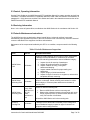
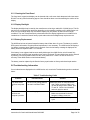
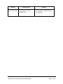
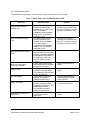
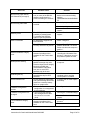
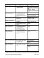
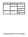
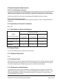
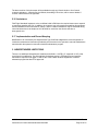
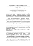
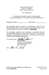
1
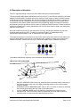
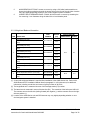
400W Series
Instructions for Continued Airworthiness
Bell 206B
Reg. No.____________
S/N_______________
Dwg. Number:
190-01226-04 Rev. 2
Garmin International, Inc.
1200 E. 151st Street
Olathe, Kansas 66062 USA
Record of Revision
Rev.
Date
Description of Change
1
2
7/16/10
8/11/10
Initial Release
Updated ref. doc. revisions in section 2.1, revised part number and weight
of item 2 in table 2.2.1.
1. INTRODUCTION................................................................................................................... 3
1.1 Purpose................................................................................................................. 3
1.2 Scope.................................................................................................................... 3
1.3 Document Control................................................................................................. 3
1.4 Permission to Use Certain Documents................................................................. 3
1.5 Definitions ............................................................................................................. 3
2. INSTRUCTIONS FOR CONTINUED AIRWORTHINESS .................................................... 4
2.1 Introduction ........................................................................................................... 4
2.2 Description of Alteration........................................................................................ 5
2.3 Control, Operating Information ............................................................................. 7
2.4 Servicing Information ............................................................................................ 7
2.5 Periodic Maintenance Instructions........................................................................ 7
2.6 Troubleshooting Information ................................................................................. 8
2.7 Removal and Installation Information ................................................................... 19
2.8 Diagrams............................................................................................................... 20
2.9 Special Inspection Requirements ......................................................................... 21
2.10 Application of Protective Treatments.................................................................... 21
2.11 Data Relative to Structural Fasteners................................................................... 21
2.12 Special Tools ........................................................................................................ 21
2.13 Additional Instructions........................................................................................... 21
2.14 Overhaul Period.................................................................................................... 21
2.15 ICA Revision and Distribution ............................................................................... 21
2.16 Assistance............................................................................................................. 22
2.17 Implementation and Record Keeping ................................................................... 22
3. AIRWORTHINESS LIMITATIONS ........................................................................................ 22
400W Series
Instructions for Continued Airworthiness Bell 206B
190-01226-04 Rev. 2
Page 2 of 22
1. INTRODUCTION
1.1 Purpose
This document is designed for use by the installing agency of the Garmin Model 400W series
GPS/WAAS Nav/Com as Instructions for Continued Airworthiness in response to Title 14 CFR Part
27.1529, Part 27 Appendix A. This ICA includes information required by the operator to adequately
maintain the Garmin 400W unit installed.
1.2 Scope
This document identifies the Instruction for Continued Airworthiness for the modification of the rotorcraft
for installation of the Garmin Models 400W series GPS/WAAS Nav/Com unit installed.
1.3 Document Control
This document shall be released, archived, and controlled in accordance with the Garmin document
control system. When this document is revised, refer to Section 2.15 for information on how to gain FAA
acceptance or approval and how to notify customers of changes.
1.4 Permission to Use Certain Documents
Permission is granted to any corporation or person applying for approval of a Garmin Model 400W series
to use and reference appropriate STC documents to accomplish the Instructions for Continued
Airworthiness and show compliance with STC engineering data. This permission does not construe
suitability of the documents. It is the responsibility of the applicant to determine the suitability of the
documents for the ICA.
1.5 Definitions
The following terminology is used within this document:
1)
2)
3)
4)
5)
6)
7)
ACO: Aircraft Certification Office
AEG: Aircraft Evaluation Group
CFR: Code of Federal Regulations
FAA: Federal Aviation Administration
ICA: Instructions for Continued Airworthiness
PMI: Principle Maintenance Inspector
STC: Supplemental Type Certificate
400W Series
Instructions for Continued Airworthiness Bell 206B
190-01226-04 Rev. 2
Page 3 of 22
2. INSTRUCTIONS FOR CONTINUED AIRWORTHINESS
2.1 Introduction
Content, Scope, Purpose and Arrangement:
This document identifies the Instructions for
Continued Airworthiness for the modification of the
rotorcraft by installation of the Garmin 400W Series
GPS/WAAS Nav/Com units.
Applicability:
Applies to Bell models 206B rotorcraft altered by
installation of the Garmin 400W Series GPS/WAAS
Nav/Com units.
Definition of Abbreviations:
See Section 1.5
Precautions:
None
Units of measurement:
None
Referenced publications:
Garmin 005-00610-03 Rev. 1 “Equipment List
400W/500W Series Installation Bell 206B STC” or
later FAA Approved Revisions
Garmin 190-01226-02 Rev. 1 “400W Series
Rotorcraft STC Installation Manual” or later FAA
Approved Revisions
Additional Maintenance Data:
Garmin 190-01226-07 Rev. 3 “400W/500W Series
Installation Bell 206B” or later FAA Approved
Revisions
Garmin 005-W0223-00 Rev. 3 “400W/500W Series
Harness Assembly Bell 206B” or later FAA
Approved Revisions
Retention:
400W Series
Instructions for Continued Airworthiness Bell 206B
This document, or the information contained within,
will be included in the rotorcraft’s permanent
records.
190-01226-04 Rev. 2
Page 4 of 22
2.2 Description of Alteration
This STC upgrades existing avionics for the Bell 206B rotorcraft as summarized below.
The Garmin Model 400W Series GPS/WAAS Nav/Com unit is a 6 ¼ inch wide unit mounted in the center
pedestal of the Bell 206B. The 400W Series units combine a large number of easily accessible controls
to use the color multi-function display, Nav and Com transceiver, GPS/WAAS navigator in a single unit.
A GPS/WAAS antenna is installed on the top of the Bell 206B forward engine cowl. The 400W Series
unit interfaces to the Garmin G500H system GDU 620 PFD/MFD for display of navigation information,
and optional cyclic stick switches for remote control of COM and HTAWS functions. A monitored avionics
cooling fan is installed in the center pedestal with a fan fail fault annunciation located in the existing Bell
206B annunciator panel.
Rotorcraft modified under this STC are restricted to VFR only, including rotorcraft that may not have
previously been restricted to VFR. To clarify this operation limitation, a placard with the text,
“APPROVED FOR DAY/NIGHT VFR” is required to be in the pilot’s view.
The installed equipment is connected to an avionics bus that receives power as soon as the battery and
avionics master switches are turned on. Circuit breakers are installed on a lower circuit breaker panel
located in the DART console as shown below. Note: dual navigator system installation as shown.
The installed 400W Series equipment can be accessed as described below:
LRU Access: Bell models 206B
1
2
3
4
5
6
1.
2.
3.
4.
GA 36/37 ANTENNA: FS80.0 remove by extracting the four mounting screws in the body of
the antenna. Note: location may vary slightly depending whether or not a dual navigator
system is installed.
OVERHEAD CIRCUIT BREAKER PANEL: FS61.0, WL 71.0 Access or remove by extracting
the mounting screws along the side of the circuit breaker panel.
CYCLIC CONTROL GRIPS: remove by extracting mounting screw at bottom of grip.
COOLING FAN: FS28.5 Access by removing copilot side (LH) cover plate. Remove by
extracting three mounting screws and disconnecting connector.
400W Series
Instructions for Continued Airworthiness Bell 206B
190-01226-04 Rev. 2
Page 5 of 22
5.
6.
400W SERIES UNIT: FS39.7 Access or remove by using a 3/32 allen head screwdriver to
loosen the locking mechanism through the access hole on the front of the unit. Note: location
may vary slightly depending whether or not a dual navigator system is installed.
LOWER CIRCUIT BREAKER PANEL: FS60.8, WL26.5 Access or remove by extracting the
four mounting ¼ turn fasteners along the sides of the circuit breaker panel.
2.2.1 Weight and Balance Information
PART NUMBER ITEM DESCRIPTION Moment ARM [IN] WEIGHT [LB] LONGITUDINAL LATERAL 4.0 GPS 400W (Unit Only) GPS 400W (Installed with rack and back plate) 011‐01057‐XX GNC 420W (Unit Only) GNC 420W (Installed with rack and back plate) 011‐01058‐XX GNC 420AW (Unit Only) GNC 420AW (Installed with rack and back plate) 011‐01059‐XX GNS 430W (Unit Only) GNS 430W (Installed with rack and back plate) 011‐01060‐XX GNS 430AW (Unit Only) GNS 430AW (Installed with rack and back plate) 011‐01061‐XX 2 GCF 3XX 3‐Port Cooling Fan (Unit Only) 013‐00103‐00 0.70 GA 36 GPS/WAAS Antenna (Unit Only) GA 37 GPS/WAAS + XM Antenna (Unit Only) 013‐00244‐00 0.47 3 013‐00245‐00 0.50 1 5.0 4.5 5.5 4.5 5.5 39.7 0.1 28.5 ‐3.2 80.0 0.0 5.1 6.2 5.1 6.2 [1] A rotorcraft weight and balance is required after installation of the 400W Series Unit. Refer to the
400W Rotorcraft STC Installation Manual listed in paragraph 2.1 of this document, for additional
information, including overall size and center of gravity location of all LRUs.
[2] The longitudinal arm is measured in terms of the fuselage station (FS) number.
[3] The lateral arm is measured in terms of the butt line (BL). The centerline of the helicopter is BL0.00.
The moment arms to the left side (looking forward) are negative (-) and the moment arms to the right
side are positive (+).
[4] Location of the 400W Series unit and GPS antenna may vary slightly depending whether or not a
dual navigator system is installed.
400W Series
Instructions for Continued Airworthiness Bell 206B
190-01226-04 Rev. 2
Page 6 of 22
2.3 Control, Operating Information
See the Pilot’s Guides or the 400W Rotorcraft STC Installation Manual for system operation and self-test
information. The 400W Rotorcraft STC Installation Manual is listed under the reference documentation in
paragraph 2.1 of this document, and the Pilot’s Guides are listed in the related documents section of the
400W Rotorcraft STC Installation Manual.
2.4 Servicing Information
None. In the event of system failure, troubleshoot the 400W Series unit in accordance with Section 2.6.
2.5 Periodic Maintenance Instructions
The 400W Series units are designed to detect internal failure. A thorough self-test is executed
automatically upon application of power to the units, and built-in test is continuously executed. Detected
errors are indicated on the equipment via failure annunciations.
Maintenance of the components installed by this STC is on condition, except as noted in the following
table.
Table 1 Periodic Maintenance Inspections
Item
Interval
Description/Procedure
Conduct a visual inspection (look for signs of wear, deterioration,
or damage to wires, backshells, or connectors) of the 400W
Series unit and wiring harnesses to ensure installation integrity:
400W Series
Unit
12 Months
400W Series
Mounting Rack
12 Months
400W Series
Mounting Rack
Every 2000
flight hours or
ten (10)
years,
whichever is
first
Avionics
Cooling Fan
12 Months
1. Inspect the unit for security of attachment.
2. Inspect all knobs and buttons for legibility.
3. Inspect condition of wiring, routing and
attachment/clamping.
4. Inspect related antennas for proper sealing and
attachment.
5. Inspect integrity of shield terminations.
6. Inspect for signs of corrosion on equipment, racks and it’s
backplates and rack mounting.
Inspect the mounting rack for any signs of excessive wear,
corrosion, or damage. Check mounting rack corners for cracks.
Check integrity of connector plate attachment to the back of
mounting rack.
Perform an electrical bonding test:
1. Remove 400W Series unit from mounting rack
2. Measure the resistance between the mounting rack and a
nearby exposed portion of aircraft metallic structure and
verify it is less than 10 milliohms.
Reinstall the 400W Series unit in the mounting rack
Conduct a visual inspection (look for signs of wear, deterioration,
or damage to wire harness and connector) of the cooling fan to
ensure installation integrity. Inspect for signs of corrosion on
equipment and mounting brackets.
400W Series
Instructions for Continued Airworthiness Bell 206B
190-01226-04 Rev. 2
Page 7 of 22
2.5.1 Cleaning the Front Panel
The front bezel, keypad, and display can be cleaned with a soft cotton cloth dampened with clean water.
DO NOT use any chemical-cleaning agents. Care should be taken to avoid scratching the surface of the
display.
2.5.2 Display Backlight
The display backlight lamp is rated by the manufacturer as having a usable life of 20,000 hours. This life
may be more or less than the rated time depending on the operating conditions of the 400W Series unit.
Over time, the backlight lamp may dim and the display may not perform as well in direct sunlight
conditions. The user must determine by observation when the display brightness is not suitable for its
intended use. Contact the Garmin factory repair station when the backlight lamp requires service.
2.5.3 Battery Replacement
The 400W series has an internal keep-alive battery that will last about 10 years. The battery is used for
GPS system information. Regular planned replacement is not necessary. The 400W series will display a
‘low battery’ message when replacement is required. Once the low battery message is displayed, the
battery should be replaced within 1 to 2 months.
If the battery is not replaced and becomes totally discharged, the 400W Series unit will remain fully
operational, but the GPS signal acquisition time may be increased. This acquisition time can be reduced
by entering a new seed position each time the unit is powered on. There is no loss of function or
accuracy of the 400W Series unit with a dead battery.
The battery must be replaced by the Garmin factory repair station or factory authorized repair station.
2.6 Troubleshooting Information
If error indications are displayed on the 400W series unit, consult the Troubleshooting section contained
below:
Table 2 Troubleshooting Guide
Problem
Possible Cause
Solution
The 400W Series
unit does not power
on.
• The unit is not getting power to
the main connector P4001.
• Make sure power is connected to the
main 78-pin connector P4001, pins
19 and 20 and ground to P4001, pins
77 and 78. Check circuit breakers
and main avionics switch.
The 400W Series
unit does not
compute a position.
• Not receiving signals.
• Check the GPS antenna connections.
Make sure the aircraft is clear of
hangars, buildings, trees, etc.
• Wait 20 minutes for unit to complete
cycle.
400W Series
Instructions for Continued Airworthiness Bell 206B
190-01226-04 Rev. 2
Page 8 of 22
Problem
Possible Cause
Solution
GPS signal levels
drop when avionics
are turned on.
• Noise interference from other
avionics.
• Turn all avionics off, then turn on each
piece one at a time to isolate the
source of the interference. Route
GPS cable and locate GPS antenna
away from sources of interference.
The GPS signal
levels are very low.
• Improper antenna installation or
coax routing.
• Check GPS antenna installation,
connections, and cable routing. The
GPS antenna must be mounted on
the top of the aircraft.
• Antenna shaded from satellites.
• Make sure the aircraft is clear of
hangars, buildings, trees, etc.
• RF interference at 1575.42 MHz • Move GPS antenna further from the
from VHF COM.
COM antenna. Add a 1575.42 MHz
notch filter in COM coax. Fix or
replace the COM. Disconnect the
ELT antenna coax to check for
possible re-radiation.
The 400W Series
unit does not
transmit.
• The PTT input is not being
pulled low.
• Check that the PTT (mic key) input is
pulled low for transmit.
• No transmit power to the COM.
• Make sure power input is connected to
the COM 25-pin connector P4002 11
and 12 and ground to P4002 21 and
22.
• The input voltage is too low.
• Increase input supply voltage to
>12VDC. (>24VDC for 430AW
models)
The sidetone level is • Wrong type of headsets, or level • If necessary, adjust the sidetone level.
too low or too high.
needs adjustment.
Sidetone adjustment is found on the
COM Setup page.
• Incompatible resolver or
• Check the resolver specifications and
OBS Resolver won’t
improper connection.
wiring.
calibrate.
OBS indication on
400W Series unit
does not agree with
OBS setting.
• 400W Series unit resolver input
not calibrated correctly.
• Check wiring and calibration.
400W Series unit is
not receiving
heading from
compass system
(ARINC 429
heading input used)
• ARINC 429 input port speed not •
correct
Check ARINC 429 input port speed
setting for port that device is
connected to and verify that the
speed is correct for that device.
• Wiring connections are
incorrect.
Check wiring.
Autopilot is not
getting GPSS/Roll
Steering data from
the 400W Series
• 400W Series unit does not have •
a position or flight plan entered.
Acquire GPS position and enter a
flight plan.
• 400W Series unit ARINC 429
•
output not configured correctly.
Check ARINC 429 output port setting
for port that autopilot is connected to.
• Resolver has not been
calibrated.
400W Series
Instructions for Continued Airworthiness Bell 206B
•
190-01226-04 Rev. 2
Page 9 of 22
Problem
unit (ARINC 429
Roll Steering used)
Possible Cause
• ARINC 429 output port speed
not correct.
• Check ARINC 429 output port speed
setting for port that autopilot is
connected to and verify that the
speed is correct for autopilot.
• Wiring connections are
incorrect.
•
• Certain autopilots require
groundspeed for GPSS to be
enabled.
• Ensure that groundspeed is provided if
required by the autopilot.
RMI pointer does
• Desired RMI source has not
not indicate correctly
been selected.
Tuning data not
updating DME
Solution
•
Check the OBI source selection on
the Main CDI/OBS Config page.
• Wiring connections are
incorrect.
•
Check wiring.
• Incorrect configuration.
•
Check the DME Channel Mode on
the VOR/LOC/GS CDI page.
• Wiring connections are
incorrect.
•
Check wiring.
ARINC 429 device
• 400W Series unit ARINC 429
•
is not receiving data
output not configured correctly.
from the
400W/420W/430W.
• ARINC 429 input port speed
•
not correct
RS-232 device is
not communicating
with the
400W/420W/430W.
Check wiring. Must be connected to
main GPS 429 output.
• Wiring connections are
incorrect.
• 400W Series unit RS-232 port
not configured correctly.
Check ARINC 429 output port setting
for port that device is connected to.
Check ARINC 429 input port speed
setting for port that device is
connected to and verify that the
speed is correct for that device.
•
Check wiring.
•
Check RS-232 port setting for port
that device is connected to.
• Improper setup on the remote
device.
•
Verify the configuration of the other
device.
• Device not compatible, or
improper connection.
•
• Multiple TX lines connected
together.
•
Verify 400W Series unit RX is
connected to remote device TX and
400W Series unit TX is connected to
remote device Rx.
Verify that there is only one TX
source per RX port.
• Wiring connections are
incorrect.
•
400W Series
Instructions for Continued Airworthiness Bell 206B
Check wiring.
190-01226-04 Rev. 2
Page 10 of 22
Problem
CDI scaling on EFS
40/50 is not correct.
Possible Cause
• On EFS 40/50, FMS #1/#2
configuration is not set to
“KLN 90-GPS”.
400W Series
Instructions for Continued Airworthiness Bell 206B
Solution
•
Reconfigure EFS 40/50 for
KLN 90-GPS” on FMS #1/#2 inputs
as appropriate.
190-01226-04 Rev. 2
Page 11 of 22
2.6.1 400W Series Alerts
The 400W Series will display a number of alerts. These are listed in the following table.
Table 3. 400W Series Alert Troubleshooting Guide
Alert Text
Airport terrain database
integrity error
Aviation database integrity
error
Basemap database integrity
error
Boot block verify failed Return unit for repair
CDI key stuck
CDI key disabled
Check unit cooling
COM has failed 420W and
430W only)
Possible Cause
Solution
• The 400W Series unit has
detected a problem with a
database on the Terrain data
card. The message
“<database name> database
integrity error” indicates the
data base in error.
• The 400W Series unit has
detected a problem with a
database on the NavData®
card. The message
“<database name> database
integrity error” indicates the
data base in error.
• The 400W Series unit has
detected a failure in the built-in
basemap (land data) database.
Land data does not appear on
the Map Page. Other unit
functions continue to work
normally.
• System integrity testing has
determined that the boot block
has become corrupted.
• The CDI key is stuck in the
enabled (or “pressed”) state.
Try pressing the CDI key again
to cycle its operation.
• “Ignore CDI key” has been
selected on the MAIN
CDI/OBS CONFIG page.
• The 400W Series unit has
detected excessive display
backlighting temperature. The
backlighting has been
automatically dimmed to
reduce the temperature.
• The unit has detected a failure
in its communications
transceiver.
• The data is not usable, try
reloading the information onto
the card. If that does not solve
the problem replace the card.
400W Series
Instructions for Continued Airworthiness Bell 206B
• The data is not usable, try
reloading the information onto
the card. If that does not solve
the problem replace the card.
• Reload the Basemap database
• Contact Garmin technical
support.
• Contact Garmin technical
support.
• Go to the MAIN CDI/OBS
CONFIG page and deselect
“Ignore CDI key”
• Check for adequate ventilation
or check cooling airflow.
• Contact Garmin technical
support.
190-01226-04 Rev. 2
Page 12 of 22
Alert Text
COM is not responding
420W and 430W only)
COM needs service
420W and 430W only)
COM push-to-talk key stuck
420W and 430W only)
COM remote transfer key is
stuck (420W and 430W only)
Possible Cause
• Internal system-to-system
communication between the
main processor and the COM
transceiver has failed.
Operational status of the COM
transceiver is unknown.
• The unit has detected a failure
in its communications
transceiver. The COM
transceiver may still be usable.
• The external push-to-talk
(PTT) switch is stuck in the
enabled (or “pressed”) state.
• Wiring is incorrect.
• The remote COM transfer
switch is stuck in the enabled
(or “pressed”) state.
Solution
• Contact Garmin technical
support. If the COM board is
still working, it will automatically
tune to 121.500 MHz. Transmit
and receive functions may still
operate regardless of the
displayed frequency.
• Contact Garmin technical
support
• Try pressing the PTT switch
again to cycle its operation.
• Check Wiring
• Try pressing the switch again to
cycle its operation.
• Verify the wiring is correct.
• If the message persists, contact
Garmin technical support.
COM transfer key stuck
420W and 430W only)
COM transmitter power has
been reduced 420W and
430W only)
Configuration error - Config
service req’d
Data transfer cancelled
(crossfill is busy)
Data transfer cancelled (data
invalid)
Data transfer cancelled
(version mismatch)
• The COM flip-flop key is stuck
in the enabled (or “pressed”)
state.
• Try pressing the switch again to
cycle its operation.
• If the message persists, contact
Garmin technical support.
• The unit has detected
excessive unit temperature.
The COM transceiver transmit
power has been automatically
reduced to compensate for the
condition.
• Insufficient voltage level
• Check for adequate ventilation
or check cooling airflow. Refer
to Section 2.7 of the Installation
Manual.
• The configuration information
has been lost or corrupted.
• Reconfigure the unit
• An attempt to transfer flight
plan data during a unit-to-unit
crossfill was cancelled.
• The host unit is busy. Wait until
any previous crossfill operation
is complete, before
reattempting the transfer.
• Select a user waypoint and reattempt the transfer.
• An attempt to transfer a single
user waypoint during a unit-tounit crossfill was cancelled.
No waypoint was specified on
the Crossfill Page.
• An attempt to transfer data
during a unit-to-unit crossfill
was cancelled. The database
versions of the two 400Wseries unit are not identical.
400W Series
Instructions for Continued Airworthiness Bell 206B
• Check the input voltage
• If necessary, update the
database(s) so they match.
190-01226-04 Rev. 2
Page 13 of 22
Alert Text
Data transfer error, please
re-transmit
Display backlight failure
Do not use for navigation
G/S has failed
420W and 430W only)
G/S is not responding
420W and 430W only)
G/S needs service
420W and 430W only)
GAD configuration required
GAD needs service
GDL 69 is not responding
Possible Cause
Solution
• An error was detected during
unit-to-unit crossfill of user
data (user waypoints and/or
flight plans).
• The 400W Series unit has
detected a failure in the display
backlighting.
• The 400W Series unit is in
Demo Mode and must not be
used for actual navigation.
• The unit has detected a failure
in its glideslope receiver.
• The data transfer should be reattempted.
• Internal system-to-system
communication between the
main processor and the
glideslope receiver has failed.
Operational status of the
glideslope receiver is
unknown.
• The unit has detected a failure
in its glideslope receiver. The
glideslope receiver may still be
usable.
• The GAD 42 Interface Adapter
has lost the configuration
information stored in its
internal memory. Any
mechanical indicators
connected to your 400Wseries unit are unusable.
• The 400W Series unit has
detected a failure in the
GAD 42 interface adapter.
Any mechanical indicators
connected to your unit are
unusable.
• No data is being received from
the GDL 69.
• Contact Garmin technical
support.
• Contact Garmin technical
support.
• Check that the DEMO MODE
SELECT pin, P5001 Pin 75, is
not connected.
• Contact Garmin technical
support.
• Contact Garmin technical
support.
• Reconfigure the GAD 42 unit.
Refer to the GAD 42 Installation
Manual
(P/N 190-00159-00)
• Refer to Section 5.2.3 of the
GAD Installation Manual (P/N
190-00159-00)
• Check for proper configuration
• Check wiring
• Contact Garmin technical
support.
• GPS antenna cable is shorted
GPS is not responding –
400W Series
Instructions for Continued Airworthiness Bell 206B
• Verify that the center conductor
is not shorted to the braid in the
coaxial cable.
190-01226-04 Rev. 2
Page 14 of 22
Alert Text
check GPS antenna (main
software version 3.20 and
later).
GPS needs service
Large magnetic variance
Loss of integrity — crosscheck NAV
Low Battery - Unit Needs
Service
MAIN processor requires
service
No altitude input is being
received
No basemap data available
Not receiving input data on
429 Channel #1 or #2
Possible Cause
• Internal system-to-system
communication between the
main processor and the GPS
receiver has failed.
Operational status of the GPS
receiver is unknown.
• The 400W Series unit has
detected a failure in its GPS
receiver.
• A valid value of magnetic
variation is not available for
this location.
• Verify all course angles
• Improper antenna installation
or coax routing
Solution
• Contact Garmin technical
support.
• Contact Garmin technical
support.
• Contact Garmin technical
support.
• Check GPS antenna
installation, connections, and
cable routing. The GPS
antenna must be mounted on
the top of the aircraft.
• Antenna shaded from satellites
• Make sure the aircraft is clear
of hangars, buildings, trees,
etc.
• RF interference at 1575.42
MHz from VHF COM.
• Move GPS antenna further
from the COM antenna. Add a
1575.42 MHz notch filter in
COM coax. Fix or replace the
COM. Disconnect the ELT
antenna coax to check for
possible re-radiation.
• Time data may have been lost
due to a memory battery
failure.
• The 400W Series unit has
detected a failure in the main
system processor.
• No altitude data is being
received from RS-232
(Serializer: Icarus, Rosetta or
Shadin) or grey code inputs.
• The 400W Series unit has
detected a failure in the built-in
basemap (land data) memory.
Land data does not appear on
the Map Page. Other unit
functions continue to work
normally.
• No data has been received on
the ARINC 429 channel #1
connection for a period
exceeding five seconds.
• Replace the battery (refer to
Section 8.4).
400W Series
Instructions for Continued Airworthiness Bell 206B
• Contact Garmin technical
support.
• Refer to Table 6-1
“RS-232 device is not
communicating with the GPS
400W/GNS430W”.
• Contact Garmin technical
support to reload the basemap
data.
• Refer to Table 6-1 “ARINC 429
device is not receiving data
from the GPS
400W/GNC420W/GNS430W”
190-01226-04 Rev. 2
Page 15 of 22
Alert Text
Possible Cause
Not receiving input data on
232 Channel #(1 through 5)
• No data has been received on
one (or more) of the RS-232
channel connections for a
period exceeding ten seconds.
Not receiving traffic data
• No traffic data is being
received.
Solution
• Refer to Table 6-1 “RS-232
device is not communicating
with the
GPS400W/GNC420W/GNS430
W”
• Check for proper configuration
• Check the wiring
OBS key stuck
OBS not available
• The OBS key is stuck in the
enabled (or pressed) state.
Try pressing the OBS key
again to cycle its operation.
• No destination waypoint has
been selected.
• The GPS receiver cannot
currently determine its position.
Obstacle database integrity
error
RAIM position warning
Searching the sky
Stored data was lost
TERRAIN configuration
conflict
TERRAIN configuration has
changed
Terrain database integrity
error
• The 400W Series unit has
detected a problem with a
database on the Terrain data
card.
• Although sufficient GPS
satellite coverage may exist,
Receiver Autonomous Integrity
Monitoring (RAIM) has
determined the information
from one or more GPS
satellites may be in error.
• The 400W Series unit is
searching the sky for GPS
satellites.
• All user waypoints, flight plans
and system settings have been
lost due to a memory battery
failure or system reset.
• The current Terrain
configuration is not supported
by the hardware.
• The unit’s terrain settings
have changed since it was
last turned on in normal
mode.
• The 400W Series unit has
detected a problem with a
database on the Terrain data
card.
400W Series
Instructions for Continued Airworthiness Bell 206B
• Contact Garmin technical
support.
• Contact Garmin technical
support.
• Select a waypoint
• Refer to Error! Reference
source not found.“The 400W
Series unit does not compute a
position.”
• The data is not usable. Try
reloading the information onto
the card. If that does not solve
the problem replace the card.
• Wait for GPS satellite geometry
to improve.
• Wait 20 minutes for unit to
complete cycle or until the
current position is located.
• If system was not reset replace
the battery.
• Reconfigure the unit.
• Reconfigure TERRAIN settings
• Contact Garmin technical
support
• Reloading the information onto
the card.
• Replace the card.
190-01226-04 Rev. 2
Page 16 of 22
Alert Text
TERRAIN has failed
Traffic device has failed
Traffic device needs service
Possible Cause
Solution
• The unit has detected a failure
in the terrain system.
• Ensure that Terrain database is
inserted in the right most card
slot.
• Reload the TERRAIN
database.
• Contact Garmin technical
support.
• The 400W Series unit cannot
communicate with the traffic
system and/or the traffic
system is reporting a system
failure.
• Check for proper configuration
• The traffic device is reporting a
system failure.
• Check for correct wiring
• Refer to the Traffic system
installation manual.
• Refer to the Traffic system
installation manual.
• A data card has been inserted,
but the format of the card is not
recognized.
• The GNC 420/GNS 430W has
detected a failure in its VLOC
receiver.
• Internal system-to-system
communication between the
main processor and the VLOC
receiver has failed.
Operational status of the
VLOC receiver is unknown.
• The unit has detected a failure
in its VLOC receiver. The
VLOC receiver may still be
usable.
• Reload the information onto the
card. If that does not solve the
problem replace the card.
• Contact Garmin technical
support.
VLOC remote transfer key is
stuck (420W and 430W only)
• The remote VLOC transfer
switch is stuck in the enabled
(or “pressed”) state.
VLOC transfer key stuck
(420W and 430W only)
• The VLOC flip-flop key is stuck
in the enabled (or “pressed”)
state.
• Try pressing the switch again to
cycle its operation.
• Contact Garmin technical
support.
• Try pressing the VLOC flip-flop
key again to cycle its operation.
User card format unknown
VLOC has failed (420W and
430W only)
VLOC is not responding
(420W and 430W only)
VLOC needs service
(420W and 430W only)
400W Series
Instructions for Continued Airworthiness Bell 206B
• Contact Garmin technical
support.
• Contact Garmin technical
support.
• Contact Garmin technical
support.
190-01226-04 Rev. 2
Page 17 of 22
Alert Text
WX-500 device has failed
Possible Cause
Solution
• The 400W- Series unit cannot
communicate with the WX-500.
• Check for proper configuration
• The WX-500 is reporting a
system failure.
• Check the wiring
• Refer to the WX-500 installation
manual for additional
troubleshooting information.
WX-500 heading has failed
• The WX-500 is reporting
invalid heading data.
• Check for proper configuration
of WX-500
• The failure may be within the
WX-500 or other connected
equipment.
400W Series
Instructions for Continued Airworthiness Bell 206B
190-01226-04 Rev. 2
Page 18 of 22
2.7 Removal and Installation Information
If any work has been done on the rotorcraft that could affect the system wiring, antenna cable, or any
interconnected equipment, verify the 400W Series unit power-up self-test sequence is successfully
completed and no failure messages are annunciated.
Whenever removing or installing units, remove power from the LRU by removing rotorcraft power or
opening the LRU circuit breaker.
2.7.1 400W Series Unit
2.7.1.1 Removal
1
2
Insert a 3/32-inch hex drive tool into the access hole at the bottom of the unit face.
Rotate the hex tool counterclockwise until the unit is forced out about 3/8 inches and can be
freely pulled from the rack.
2.7.1.2 Installation
1
2
3
Slide the 400W unit in the rack straight in until it stops, about 1 inch short of the final position.
Insert the hex drive tool into the access hole at the bottom of the unit face.
Rotate the hex tool clockwise while pressing on the left side of the bezel until the unit is firmly
seated in the rack.
NOTE
The installation configuration and user settings are stored internally in the 400W Series
unit, and will be lost when the 400W Series is replaced with a new unit.
Original 400W Series unit is Reinstalled
If the original 400W Series is reinstalled, then no configuration is required.
New, Repaired or Exchange 400W Series is Installed
If the 400W Series unit is removed for repair and reinstalled, or if the 400W unit is removed and replaced
with a different 400W Series unit, then verify the correct software versions are on the 400W Series unit
as specified in the Equipment List 400W/500W Series Installation Bell 206B STC listed in paragraph 2.1
of this document. In addition, complete the ‘Post Installation Configuration & Checkout Procedures’
contained in the 400W Rotorcraft STC Installation Manual listed in paragraph 2.1 of this document to
restore the proper installation configuration settings.
2.7.1.3 Return to Service
After removing and reinstalling the 400W Series unit per the instructions above, verify that the power-up
self-test sequence is successfully completed and no failure messages are annunciated.
Note: There are no special handling requirements for the 400W Series units.
2.7.2 GA 36 GPS and GA 37 GPS/XM Antennas
2.7.2.1 Removal
1 Remove the screws from the outside of the rotorcraft.
400W Series
Instructions for Continued Airworthiness Bell 206B
190-01226-04 Rev. 2
Page 19 of 22
2
3
Remove old sealant. Insert a 3/32-inch hex drive tool into the access hole at the bottom of the
unit face.
Lift the antenna off the rotorcraft and detach the coax (from the outside). If a GA 37 antenna
verify coax(s) are properly labeled with correct color band. Note: GPS coax is labeled with a blue
band and XM cable with a yellow band.
2.7.2.2 Installation
For GA 36 or GA 37 GPS antenna installation, follow the installation procedures contained in the
installation drawing listed in paragraph 2.1 of this document.
2.7.2.3 Return to Service
After removing and reinstalling the GPS antenna, verify the 400W Series unit power-up self-test
sequence is successfully completed and no failure messages are annunciated. If the unit is unable to
acquire satellites, move the rotorcraft away from obstructions which might be shading GPS reception. If
the situation does not improve, check the GPS antenna installation.
2.7.3 Cooling Fan
2.7.3.1 Removal
1
2
3
4
Extract the screws from the copilot side (LH side) center console cover plate.
Remove copilot side (LH side) center console cover plate.
Disconnect cooling fan electrical connector located under cooling ports on fan.
Extract the three (3X) cooling fan mounting screws to remove cooling fan.
2.7.3.2 Installation
1
2
3
Install cooling fan using removed hardware.
Reconnect electrical connector to cooling fan.
Reinstall center consol cover plate using removed hardware, verifying silicone sponge foam used
to seal cooling fan intake remains in place on center console cover plate and properly seals the
fan intake to the louver installed on the center console cover plate.
2.7.3.3 Return to Service
After removing and reinstalling the cooling fan verify proper operation of the cooling fan. Apply power to
the avionics, verify the cooling fan is operating and the FAN FAIL light on the annunciator panel is not
illuminated.
2.8 Diagrams
Rotorcraft specific LRU locations and wire routing diagrams are contained in the 400W/500W Series
Installation drawing Bell 206B, listed in Section 2.1 of this document Point to point wiring diagrams are
in the Appendix of the 400W Rotorcraft STC Installation Manual. Refer to the GNS 400W Series PostInstallation Checkout Log retained in the rotorcraft permanent records for a list of the interfaced
equipment and port configurations.
400W Series
Instructions for Continued Airworthiness Bell 206B
190-01226-04 Rev. 2
Page 20 of 22
2.9 Special Inspection Requirements
2.9.1 Post-Lightning Strike Inspection
In the event of a suspected or actual lightning strike to the rotorcraft, the GA 36 or GA 37 GPS antenna
installation shall be inspected to ensure that there is no structural damage around the areas where
lightning may have attached. If there is visible sign of damage to the antenna then it must be replaced.
Verify that the 400W series unit receives and displays GPS satellite information normally.
2.9.1 Post-Hard Landing Inspection
In the event of a hard landing complete all the inspections specified in Table 1 Periodic Maintenance
Inspections.
2.10 Application of Protective Treatments
None, N/A.
2.11 Data Relative to Structural Fasteners
FASTENER TYPE AND TORQUE Location 6‐32 Screw 8‐32 Screw 10‐32 Screw (see Installation Drawing) 12‐15 inch‐pounds 12‐15 inch‐pounds 22‐25 inch‐pounds 400W Unit Mounting Rack X GPS Antenna X Cooling Fan X X X 2.12 Special Tools
For electrical bonding testing, a milliohm meter is required.
2.13 Additional Instructions
None
2.14 Overhaul Period
The system does not require overhaul at a specific time period. Power on self-test and continuous BIT
will monitor the health of the 400W Series unit. If the unit indicates an internal failure, the unit may be
removed and replaced. See troubleshooting section 2.6 contained in this document.
2.15 ICA Revision and Distribution
To revise this ICA, a letter must be submitted to the ACO along with the revised ICA. The ACO will
obtain AEG acceptance, and approve any revision to the Airworthiness Limitations in Section 3. After
FAA acceptance/approval, Garmin will release the revised ICA for customer use, and provide any
required notification of the revision.
400W Series
Instructions for Continued Airworthiness Bell 206B
190-01226-04 Rev. 2
Page 21 of 22
The latest revision of this document will be available through any Garmin dealer or from Garmin
customer assistance. A Garmin Service Bulletin, describing ICA revision, will be sent to dealers if
revision is determined to be significant.
2.16 Assistance
FAA Flight Standards Inspectors or the certificate holder’s PMI have the required resources to respond
to questions regarding this ICA. In addition, the customer may refer questions regarding this equipment
and its installation to the manufacturer, Garmin. Garmin customer assistance may be contacted during
normal business hours via telephone 913-397-8200 or email from the Garmin web site at
www.garmin.com.
2.17 Implementation and Record Keeping
Modification of an rotorcraft by this Supplemental Type Certificate obligates the rotorcraft operator to
include the maintenance information provided by this document in the operator’s rotorcraft maintenance
manual and/or the operator’s rotorcraft scheduled maintenance program.
3. AIRWORTHINESS LIMITATIONS
There are no additional Airworthiness Limitations as defined in 14 CFR § 27, Appendix A. A27.4 that
result from this modification. The Airworthiness Limitations section is FAA approved and specifies
maintenance required under §§43.16 and 91.403 of the Federal Aviation Regulations unless an
alternative program has been FAA approved.
400W Series
Instructions for Continued Airworthiness Bell 206B
190-01226-04 Rev. 2
Page 22 of 22