1
Installation Guide v1.0
MFD8/12/BB
READ ME FIRST!
Please read this document before installing and
powering ON your NavNet Display
INSTALLATION TOOLS YOU WILL NEED: An ordinary USB MOUSE
AND USB KEYBOARD for the MFDBB Installation! These are also helpful
with the MFD8/12 Installation.
www.furunousa.com
Contents
1. Mounting ................................................................................................................ 11 1.1. MFD8/12 Mounting ........................................................................................... 11 1.1.1. MFD8/12 Flush Mounting .......................................................................... 12 1.1.2. MFD 8/12 Desktop and Overhead Mounting ............................................. 14 1.2. MFDBB Processor Mounting ............................................................................ 15 1.2.1. MFDBB Processor Desktop or Deck Mounting .......................................... 15 1.2.2. MFDBB Processor Bulkhead Mounting ..................................................... 16 1.2.3. MDBBB Keyboard Mounting ...................................................................... 16 2. Wiring ..................................................................................................................... 19 2.1. Overview .......................................................................................................... 19 2.1.1. MFD8/12 Overview .................................................................................... 19 2.1.2. MFDBB Overview ...................................................................................... 20 2.2. Power Connections .......................................................................................... 20 2.2.1. MFD8/12 .................................................................................................... 20 2.2.2. MFDBB ...................................................................................................... 20 2.3. DATA Ports (NMEA0183)................................................................................. 22 2.3.1. Overview.................................................................................................... 22 2.3.2. DATA 1 description .................................................................................... 22 2.3.3. DATA 2 Description ................................................................................... 23 2.4. NMEA2000 Description and Information .......................................................... 25 2.4.1. MFD ........................................................................................................... 25 2.4.2. DRS Radar ................................................................................................ 25 2.4.3. NMEA2000-0183 Data Conversion and NMEA2000 Bridging ................... 26 2.5. DRS (Radar) Connection ................................................................................. 27 2.5.1. Connecting the DRS to MFD8/12 .............................................................. 28 2.5.1. Connecting the DRS to MFDBB ................................................................ 29 2.6. Network ............................................................................................................ 30 2.6.1. Introduction ................................................................................................ 30 2.6.2. Power Synchronization .............................................................................. 31 2.7. Video Inputs ..................................................................................................... 33 2.7.1. Analog Video ............................................................................................. 34 2.7.2. IP Camera ................................................................................................. 34 2.8. External Monitors ............................................................................................. 36 2.8.1. MFD8/12 .................................................................................................... 36 2.8.2. MFDBB ...................................................................................................... 36 2.9. USB and Audio Connection.............................................................................. 37 2.9.1. USB Ports .................................................................................................. 37 2
2.9.2. Audio ......................................................................................................... 39 2.10. MFD8/12 Video, USB and Audio Connection ............................................... 39 2.10.1. Waterproof Connection .......................................................................... 39 2.10.2. Non Waterproof connection .................................................................... 42 3. Configuration .......................................................................................................... 43 3.1. Introduction ...................................................................................................... 43 3.1.1. Selecting a Master ..................................................................................... 44 3.1.2. Data Source Selection ............................................................................... 44 3.1.3. Installation Wizard Conceptual Description ............................................... 44 3.2. Installation Wizard Own Settings...................................................................... 45 3.2.1. Own Settings (Master, Power Synchronization, Monitor)........................... 46 3.2.2. NMEA2000 Data Configuration ................................................................. 47 3.2.3. NMEA0183 ................................................................................................ 48 3.3. Installation Wizard Global Settings................................................................... 51 3.3.1. Boat Parameter Settings............................................................................ 51 3.3.1. Engine Parameters (Analog Display) ......................................................... 52 3.3.2. Assigning Nicknames ................................................................................ 53 3.3.3. Camera Names ......................................................................................... 54 3.3.4. Primary Data Source selection .................................................................. 54 3.3.5. Sounder Configuration ............................................................................... 57 3.3.6. DRS (Radar) Configuration........................................................................ 59 3.4. MFDBB Keyboard/Processor Linking ............................................................... 61 4. Registering the System .......................................................................................... 62 4.1. SystemID Description ....................................................................................... 62 4.2. Registration Card ............................................................................................. 62 5. Appendix ................................................................................................................ 63 5.1. Example NN3D System Configurations ........................................................... 63 5.1.1. Basic Plotter/Fish Finder Installation ......................................................... 63 5.1.2. Basic Plotter/Radar/Fish Finder Installation ............................................... 64 5.1.3. Dual MFD Installation Example ................................................................. 66 5.1.4. Dual Screen MFDBB Installation with Pilot Integration .............................. 67 5.2. Configuring AXIS IP Cameras .......................................................................... 69 5.2.1. Introduction: ............................................................................................... 69 5.2.2. Setting the IP of the computer ................................................................... 69 5.2.3. Set up the IP address of the camera ......................................................... 71 5.2.4. Configure the camera ................................................................................ 75 3
4
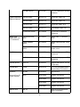
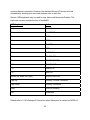
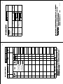
Standard supply (MFD8/12)
Name
Multi Function
Display
Installation
materials
Spare Parts
Accessories
Part Number
(PN)
Qty
MFD8
-
1
MFD12
-
Type
CP19-00900
000-011-780
CP19-01000
000-011-781
SP19-00701
001-028-020
SP19-00801
001-028-030
FP19-01101
001-023-060
Remarks
Choose one.
1 set
For MFD8, CP19-00901*, cables
For MFD12, CP19-01001*, cables
1 set
For MFD8, fuses
For MFD12, fuses
1 set
Panel/Bezel Removal tool
*See the lists at the end of this manual.
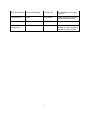
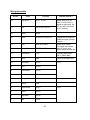
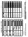
Optional supply (MFD8/12)
Name
Cable Assemblies
Types
Part Number (PN)
Remarks
MJ-A7SPF0007-050C
000-154-028
5 m, NMEA0183, w/7 pin
Female connector(DATA1)
NMEA0183 and
NMEA2000 Micro- M12-05BM+05BF-010
Cables
000-167-962
φ6, 1 m, NMEA2000, w/M-F
micro connectors
M12-05BM+05BF-020
000-167-963
φ6, 2 m, NMEA2000, w/M-F
micro connectors
M12-05BM+05BF-060
000-167-964
φ6, 6 m, NMEA2000, w/M-F
micro connectors
M12-05BFFM-010
000-167-965
φ6, 1 m, NMEA2000, w/micro
connector
M12-05BFFM-020
000-167-966
φ6, 2 m, NMEA2000, w/micro
connector
5
M12-05BFFM-060
000-167-967
φ6, 6 m, NMEA2000, w/micro
connector
MOD-Z072-020+
000-167-175
LAN cross, 4-pair, 2 m
MOD-Z072-050+
000-167-176
LAN cross, 4-pair, 5 m
MOD-Z072-100+
000-167-177
LAN cross, 4-pair, 10 m
MOD-Z073-030+
000-167-171
LAN straight, 2-pair, 3 m
MJ-A6SPF0016-005C
000-159-689
For FAX-30, ETR6N/10N
connection
LTWSS050505FMFTS001
000-168-603
NMEA 2000 “T” Connector,
micro
LTWMC-05BMMTSL8001
000-168-604
NMEA 2000 terminator, male,
micro
LTWMC-05BFFTSL8001
000-168-605
NMEA 2000 terminator,
female, micro
DVI-D/D SINGLELINK
000-149-054
5 m, for Multi-purpose LCD
connection
DVI-D/D S-LINK
000-150-200
10 m, for Multi-purpose LCD
connection
External Buzzer
OP03-136
000-086-443
Suggest Radio-Shack 273-070
or equivalent
Junction Box
FI-5002
000-010-765
For FI-50 series/NMEA2000
Terminal Strip Connections
Rectifiers
RU-3423
000-030-443
w/o PSU-012
Furuno AC-to-DC
Power Supplies
PR-62
000-013-484
100VAC, w/PSU-012
000-013-485
110VAC, w/PSU-012
000-013-486
220VAC, w/PSU-012
000-013-487
230VAC, w/PSU-012
Cable Assemblies
Ethernet Network
NMEA 2000
Terminators and
“T” Connectors
DVI-D Cable
Network Hub
HUB-101
-
6
NN3D Hub with Sleep Mode
Signal Compatibility
RJ45 Junction Box RJ45-to-RJ45 Straight
RJ4-5CN-STR
For Mast-Step or LAN cable
extension
Connector Boot
001-028-090
Waterproofing Kit for MFD8/12
exposed connection points
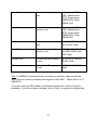
OP19-7
Operator’s Manual OME-4440
NMEA 2000
Interface Unit
000-167-802
IF-NMEA2K1
-
7
Use where NMEA2000-toAD10/0183 Data conversion is
required for legacy products
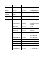
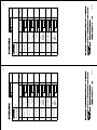
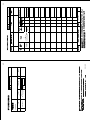
Standard supply (MFDBB)
Name
Type
Code No.
Qty
Processor Unit
MPU-001
-
1
Control Unit
MCU-001
-
1
Display Control Unit
DCU12
-
1
Remarks
Choose one.
Installation Materials CP19-00600
000-011-664
1 set
For MPU-001, Cable, CP1900601*
CP19-00700
000-011-663
1 set
For MCU-001,
cable, CP1900701*
CP19-00800
000-011-662
SP19-00501
001-023-090
1 set
For MPU-001, fuses
SP19-00601
001-023-040
1 set
For DCU-001, fuses
FP19-01201
001-033-760
1
FP19-01101
001-023-060
Spare Parts
Accessories
Choose one.
For DCU12,
cables, CP1900801*
For MCU-001, panel remover
For DCU12, panel remover
*See the lists at the end of this manual.
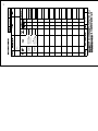
Optional supply (MFDBB)
Name
DVI-D Cable
External Buzzer
Types
Code No.
Remarks
DVI-D/D SINGLELINK
000-149-054-10
5m
DVI-D/D S-LINK
000-150-200-10
10 m
OP03-136
000-086-443
8
Rectifier
RU-1746B-2
-
Network Hub
HUB-101
-
Joint Box
TL-CAT-012
000-167-140-10
For LAN cable extension
Junction Box
FI-5002
000-010-765
For NMEA 2000
Control Unit
MCU-001
-
Display Control
Unit
DCU12
-
Cable Assy
MJ-A7SPF0007-050C
000-154-028-10
5 m, NMEA0183, w/7P
connector
MJ-A6SPF0016-005C
000-159-689-11
For FAX-30, ETR6N/10N
connection
MOD-Z072-020+
000-167-175-10
2 m, LAN
MOD-Z072-050+
000-167-176-10
5 m, LAN
MOD-Z072-100+
000-167-177-10
10 m, LAN
MOD-Z073-030+
000-167-171-10
3 m, for PC connection
M12-05BM+05BF-010
000-167-962-10
φ6, 1 m, NMEA 2000
M12-05BM+05BF-020
000-167-963-10
φ6, 2 m, NMEA 2000
M12-05BM+05BF-060
000-167-964-10
φ6, 6 m, NMEA 2000
M12-05BFFM-010
000-167-965-10
φ6, 1 m, NMEA 2000
M12-05BFFM-020
000-167-966-10
φ6, 2 m, NMEA 2000
M12-05BFFM-060
000-167-967-10
φ6, 6 m, NMEA 2000
CB-05PM+05BF-010
000-167-968-10
φ10, 1 m, NMEA 2000
9
NMEA connector
CB-05PM+05BF-020
000-167-969-10
φ10, 2 m, NMEA 2000
CB-05PM+05BF-060
000-167-970-10
φ10, 6 m, NMEA 2000
CB-05BFFM-010
000-167-971-10
φ10, 1 m, NMEA 2000
CB-05BFFM-020
000-167-972-10
φ10, 2 m, NMEA 2000
CB-05BFFM-060
000-167-973-10
φ10, 6 m, NMEA 2000
LTWSS-050505-FMFTS001
000-168-603-10
NMEA 2000 distributor
(micro style)
LTWMC-05BMMTSL8001
000-168-604-10
NMEA 2000 terminator,
male (micro style)
LTWMC-05BFFTSL8001
000-168-605-10
NMEA 2000 terminator,
female (micro style)
LTWNC050505FMFTS001
000-160-507-10
NMEA 2000 distributor
(mini style)
LTWMN-05AMMTSL8001
000-160-508-10
NMEA 2000 terminator,
male (mini style)
LTWMN-05AFFTSL8001
000-160-509-10
NMEA 2000 terminator,
female (mini style)
Operator’s Manual OME-44460
-
NMEA 2000
Interface Unit
-
IF-NMEA2K1
10
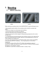
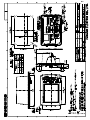
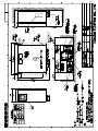
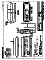
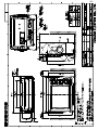
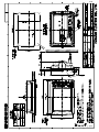
1. Mounting
1.1.
MFD8/12 Mounting
MFD8
MFD12
When selecting a mounting location for the NN3D MFD8/12, keep the following in mind:
• The temperature and humidity of the mounting location should be moderate and
stable.
• Install the unit away from exhaust pipes and ventilators.
• The mounting location should be well ventilated.
• Mount the unit where shock and vibration are minimal.
• Keep the unit away from electromagnetic field generating equipment such as motors
and generators.
• For maintenance and checking purposes, leave sufficient space from the sides and the
rear of the unit and leave slack in cables. Minimum recommended space is shown the
outline drawing for the display units.
•Test and Confirm that the Operator LCD Viewing Angle, which is fixed, is acceptable
before permanent MFD8/12 installation. This is very important for Flush Mount
Installations!
• A magnetic compass will be affected if the display unit is placed too close to it.
Observe the compass safe distances shown in the SAFETY INSTRUCTIONS to prevent
disturbances to the magnetic compass.
The MFD8/12 can be flush or bracket mounted in a variety of ways.
11
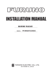
1.1.1. MFD8/12 Flush Mounting
1. Prepare a cutout in the mounting location using the template sheet (supplied) for the
MFD8 or 12.
2. Remove the front panel from the MFD by grasping it at its sides and pulling it
towards you.
3. Attach the mounting gasket (sponge) to the display unit.
4. Fix the display unit by using four self-tapping screws (supplied).
5. Attach the front panel to the display
12
How to detach the front cover when flush mounted.
To detach the front panel when the unit is flush mounted, use the special tool (supplied)
as below. Note that the front cover may be damaged if this procedure is not followed!
1. Insert the tool in the notch on the lower side of the unit
2. Pull the tool to raise the panel slightly. Repeat this action for all notches on the
lower side of the unit
3. Insert the tool into the small notches located on the sides of the panel, and pull
the tool to raise the panel slightly
13
4. Use your hands to detach the front panel from the lower side.
1.1.2. MFD 8/12 Desktop and Overhead Mounting
Follow the procedure below to mount the MFD8 or 12 on a desktop or overhead.
1. For MFD12, attach the liner to each side of the display unit. (Reverse the
MFD12 Liners for overhead mounting.)
2. Fix the bracket (Hanger) by using self-tapping screws (supplied).
3. Screw knob bolts into the display unit, set it to the bracket (Hanger), and tighten
the knob
14
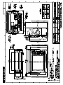
1.2.
MFDBB Processor Mounting
The unit can be mounted on the deck, a desktop or on a bulkhead. Take special note
that the MFDBB IS NOT WATERPROOF. Select a mounting location considering the
points below:
• Select a location where temperature and humidity are moderate and stable.
• Consider the lengths of the cables connected among the processor unit, radar sensor
and control unit.
• For mounting on a bulkhead, be sure the mounting location is strong enough to
support the unit under the pitching and rolling normally encountered on the vessel.
• Leave sufficient space around the unit for maintenance and servicing. Recommended
maintenance space appears in the outline drawing at the back of this manual.
• A magnetic compass will be affected if the processor unit is placed too close to the
magnetic compass. Observe the compass safe distances in SAFETY INSTRUCTIONS
to prevent disturbance to the magnetic compass.
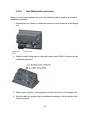
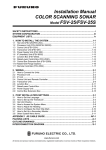
1.2.1. MFDBB Processor Desktop or Deck Mounting
Fasten with four self-tapping screws.
15
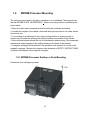
1.2.2. MFDBB Processor Bulkhead Mounting
Mark four fixing holes positions on the bulkhead. Screw in two 6x30 self-tapping screws
at upper fixing positions, leaving 5 mm protruding. Set the processor unit to the screws
and screw in two self-tapping screws at lower positions. Tighten all screws.
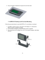
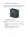
1.2.3. MDBBB Keyboard Mounting
The BlackBox keyboard (control unit MCU-001) is designed to be flush mounted in a
console or panel.
1. Prepare a cutout in the mounting location using the template sheet (supplied) for
the MCU-001.
2. Remove the front panel from the MCU-001 by grasping it at its sides and pulling
it towards you.
3. Attach the mounting gasket (sponge) to the MCU-001.
4. Fix the MCU-001 by using four self-tapping screws (supplied).
5. Attach the front panel to the MCU001
16
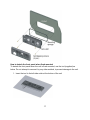
How to detach the front panel when flush mounted
To detach the front panel when the unit is flush mounted, use the tool (supplied) as
below. Do not attempt to remove it by any other method, to prevent damage to the unit.
1. Insert the tool to the left-side notch at the bottom of the unit
17
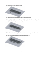
2. Pull the tool to raise the panel slightly
3. Similarly use the tool to raise the panel at the right-side notch.
4. Insert the tool to the space at the one end of the unit, and pull it to raise the panel
slightly. Repeat this procedure for the opposite side
5. Use the tool to raise the panel at the two notches on the upper side of the unit.
6. Use your hands to detach the front panel at both sides of it
18
2. Wiring
2.1.
Overview
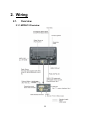
2.1.1. MFD8/12 Overview
19
2.1.2. MFDBB Overview
2.2.
Power Connections
2.2.1. MFD8/12
The MFD8/12 can be powered directly using nominal 12V or 24V DC.
Only use the power cable supplied with the unit and connect it to the Power Connector
at the rear of the unit.
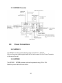
2.2.2. MFDBB
The MCU001 - MFDBB processor unit can be powered using 12V or 24V.
Make the power cable as shown below.
20
To connect the power cable, remove the Power Terminal cover. Unfasten the four pan
head screws and connect the power cable to the power terminal (upper: +, lower: -).
Reattach the cover. Note that the recommended maximum cable length is 5 m.
21
2.3.
DATA Ports (NMEA0183)
2.3.1. Overview
Every MFD8/12 and MFD BB has THREE full NMEA0183 I/O Data Ports. One is
available on the DATA1 7-Pin Connector and is pin compatible with Navnet 1/vx2
DATA1 Connector. Two additional NMEA Ports are available on the DATA2 18-Pin
connector.
These NMEA connections can accept a baud rate of 4800 or 38.4K. Any instrument
(GPS, AIS, Smart Sensor, etc…) can be connected to any port.
Heading input to NavNet 3D will allow functions such as Radar Overlay and course
stabilization (North Up, Course Up, etc.) in Radar operating modes. The NMEA 0183
heading refresh rate needs to be 100ms (or faster) in order for the Radar ARPA function
to work properly. If ARPA is not used, the refresh rate of heading information can be
200ms (5 times per second) to support radar overlay on the plotter. NavNet 3D will not
accept heading if the refresh rate is only set to 1 sec. NMEA0183 heading can be
accepted on any NMEA port at a baud rate up to 38.4kbps. Note that changing the
baud rate on any of the three NMEA0183 Data ports will affect both the receive and
transmit baud rate. In other words, data sent and received must use the same baud
rate for each individual data port.
Please refer to the Appendix for installation example with the Furuno Pilot or Magnetic
Compass PG500R
Note: - Heading data from a NMEA2000 source/sensor will always be at the correct
refresh speed for the DRS ARPA function
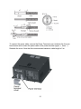
2.3.2. DATA 1 description
DATA1 uses a 7 Pin round plug. Usually, DATA1 will be used to directly connect a
Furuno GPS GP320B (BBWGPS).
Other NMEA0183 compatible device (Compass, AIS, Sounder, Smart Sensor…) can be
connected by using a 7pin connector-to-pigtail cable (P/N 000-154-028).
22
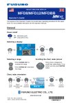
Wiring Information
Pin No.
Color
Function
7
Shield
Shield
6
Black
GND
5
Red
12V_OUT
4
Green
RD1-C
3
Yellow
RD1-H
2
Blue
TD1-B
1
White
TD1-A
2.3.3. DATA 2 Description
DATA2 can be used to connect additional NMEA 0183 instruments. Use the included
cable assembly FRUDD-18AFFM-L180 (FUSA P/N 000-164-608). This included PigTail Cable has an 18-Pin connector. DATA2 also provides additional Inputs/Outputs
(Buzzer, Event …). For example, a MOB contact closure input may be connected to PIN
15 and 11*.
*Note that any MFD will interface to virtually any MOB System or Event switch (Point
Save) contact closure signal using these pins.
23
Wiring Information
Pin No.
Color
Function
Remark (Port No.)
18
Light green
NET-C IN (0V)
NMEA 2000 Power IN.
When 12V DC power is
applied on these pins, the
N2K port will be powered
(up to 1 ampere)
17
Pink
NET-S IN (+12V IN)
16
Purple
Shield
15
White
BUZZER or EVENT IN
External Buzzer Output or
MOB/Event Input (Contact
Closure)
14
Gray
SPEED-ALARM C
13
Yellow
SPEED-ALARM H
Speed alarm contact.
Can trigger and external
alarm or device when
speed reaches a setup limit
12
Black/White
+12V
External buzzer power
ONLY (100mA Max)
11
Black
GND
GND for Event/MOB Input
10
Blue/White
RD3-C
Port 3
9
Blue
RD3-H
8
Green/White
TD3-B
7
Green
TD3-A
6
Orange/White
GND
5
Orange
GND
4
Brown/White
RD2-C
3
Brown
RD2-H
2
Red/White
TD2-B
1
Red
TD2-A
Port 2
24
2.4.
NMEA2000 Description and Information
2.4.1. MFD
Every MFD has one NMEA2000 port (Standard “DeviceNet Micro” style connector).
This port is not powered unless External Power is applied on Pin 18 and 17 of DATA2
and must be connected to a properly configured NMEA2000 network.
IMPORTANT: Each MFD is designed to connect to separate NMEA2000
Networks/Backbones! All MFD and DRS use “Ethernet Bridging” to link separate
NMEA2000 networks/backbones. NEVER connect NMEA2000 ports between MFDs
and/or DRS products.
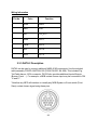
2.4.2. DRS Radar
In addition to the NMEA2000 port found on the MFD processor, all DRS radar sensors
have one powered NMEA2000 port (Terminal Strip connector). You may directly
connect various Furuno NMEA2000 sensors to the DRS radar sensor without having to
run a separate NMEA2000 cable up the mast. The total number of sensors that can be
connected to the NMEA2000 DRS port without external power connection depends on
power consumption. The DRS can supply up to 1 amp (20 LEN) to the DRS NMEA2000
network.
Please note that the NMEA2000 network connected to the DRS is its own independent
NMEA2000 Backbone and needs to be terminated at both ends by a Terminating
Resistor. A 120 Ohm resistor is standard supply with the DRS to terminate the NMEA.
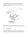
For example, if you install a SC30, WS200, or GP330 with the DRS NMEA2000 Port,
you must have two terminators in the backbone. One can be at the sensor and the
other located inside the DRS as shown below:
Please refer to the DRS Installation Guide for more information about connection
25
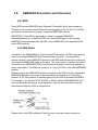
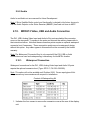
2.4.3. NMEA2000-0183 Data Conversion and NMEA2000 Bridging
NMEA0183 to NMEA2000 conversion
NMEA0183 sentences and NMEA2000 PGNs, which are used and accepted in the MFD
network can be converted and output in either/both NMEA0183/NMEA2000 formats.
Note that only one type of data can be converted and output at a time (one position, one
depth, one heading…). In case of multiple GPS, the position output is the one currently
selected in an MFD network. This NN3D prioritizing function allows NMEA2000
products to utilize older NMEA0183 sensors and vice-versa. For example, you can
connect a NMEA0183 Wind Instrument such as the Furuno PB100 to NavNet3D, and
have the corresponding information output on one (or several) MFD NMEA2000 ports to
feed a NMEA2000 display such as the Furuno FI50. The opposite is also true.
Ethernet Bridging of Individual NMEA2000 Networks/Backbones
You may ONLY connect one MFD or DRS to the same NMEA2000 Network. Some
NN3D vessels may contain several smaller NMEA2000 Networks where data from each
NMEA2000 network is linked via the High-Bandwidth NN3D Ethernet Network. In these
cases, each separate NMEA2000 network will be “Bridged” together via the NN3D
Ethernet Network. NN3D MFD and DRS NMEA2000 ports shall also not be connected
together. In the case where NMEA2000 engine data, or other ship’s data, is introduced
to the NN3D Network, the connection is made to only one MFD, and this MFD will
bridge the data to other MFDs in the network.
26
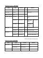
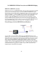
2.5.
DRS (Radar) Connection
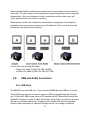
Up to two DRS (Digital Radar Sensors) can be connected to a NavNet3D network.
Every DRS comes with a supplied 15 Meter cable (FUSA P/N 000-167-636). Other
cable lengths may be purchased if necessary (Note that the part numbers for the
DRS25A are different):
- 10 Meter Cable (FUSA P/N 000-167-635)
- 20 Meter Cable (FUSA P/N 000-167-637)
- 30 Meter Cable (FUSA P/N 000-167-638)
The Radar cable is a “Siamese” type cable that carries power (48V) and Data
(Ethernet). All MFD have a dedicated Power Port (48V) used to connect the Radar
Power Cable. Some combinations require an additional Power Supply Unit (PSU) in
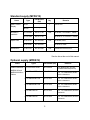
order to provide enough power for the DRS. Please refer to the following table:
DRS2D
MFD8
MFD12
MFDBB
DRS4D
DRS4A
PSU-012
DRS6A
PSU-012
DRS12A
PSU-012
PSU-012
Note: DRS25A antenna includes PSU-013 as standard supply
27
DRS25A
PSU-013
PSU-013
PSU-013
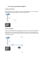
2.5.1. Connecting the DRS to MFD8/12
Standalone Installation:
When the MFD8/12 and the Radar are the only Ethernet sensors, you can connect the
Radar Ethernet connection directly to the back of the MFD8/12.
Network Installation:
As soon as multiple MFD8/12 or other Ethernet sensors (i.e. DFF1 Fish Finder, BBWX1
Sirius receiver, etc.) are used, the Radar Ethernet connection must be connected to an
Ethernet Hub. In this case an Ethernet coupler can be used to extend the Ethernet part
of the Siamese Cable
28
Example of straight Ethernet Coupler (FUSA P/N= RJ4-5CN-STR):
Note: This Ethernet coupler is not waterproof.
Ethernet Cables that can be used to extend the Ethernet Radar Connection:
- 2 Meter RJ45 to RJ45 Ethernet Cable (P/N 000-167-175)
- 5 Meter RJ45 to RJ45 Ethernet Cable (P/N 000-167-176)
- 10 Meter RJ45 to RJ45 Ethernet Cable (P/N 000-167-177)
Please refer to the DRS Installation Guide for more information on connections inside
the antenna
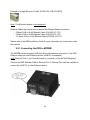
2.5.1. Connecting the DRS to MFDBB
The MFDBB has an integrated HUB that allows simultaneous connection of the DRS
Ethernet cable and other Ethernet devices (HUB101 for example).
Note: Ethernet Ports 1 and 2 are dedicated for connection of the MCU001Keyboard.
Connect the DRS Ethernet Cable to Ethernet Port 3. Ethernet Port 4 will be available to
connect the HUB 101 or other Ethernet sensor
29
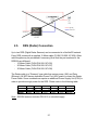
2.6.
Network
2.6.1. Introduction
NavNet3D (just like NavNet1 and VX2) uses standard TCP/IP Ethernet to share
radar/sounder images and other navigation information from devices connected within a
networked system. In any single NavNet 3D network, a combination of up to ten
NavNet3D MFDs may be connected to each other. All NavNet3D Network Components
have one integrated regular RJ45 Ethernet port (with the exception of the MFDBB which
has an integrated hub). Legacy NavNet components such as the ETR-6/10N (FUSA
P/N BBFF1) or ETR-30N (FUSA P/N BBFF3) network sounder will need to be
connected using the Hub Adapter Cable 6 Pin to RJ45 (FUSA P/N = 000-144-463).
MFD8/12
The MFD8/12 has one Waterproof Ethernet Port on the rear of the unit. It comes with
standard supply of a 3 meter Ethernet Cable (FUSA P/N =000-164-809) terminated at
one end with a Waterproof connector and at the other end with a regular RJ45.
This cable can be extended using a coupler (FUSA P/N= RJ4-5CN-STR) and a regular
Ethernet Cable. Please note that the coupler is not waterproof and thus need to be
installed accordingly.
MFDBB
The MFDBB Processor Unit contains an integrated hub that provides 4x Ethernet ports.
Two of these ports are exclusively dedicated to the keyboard (control unit MCU001)
connection. The MFDBB keyboard must be directly connected to one of the dedicated
Ethernet ports on the BB (the MCU001 Control Unit cannot be connected to an Ethernet
Hub/Switch). The Keyboard comes standard with a 5 meter Ethernet cable, but other
lengths may be used:
Ethernet Cable that can be used to connect the MFDBB Keyboard:
- 2 Meter RJ45 to RJ45 Ethernet Cable (P/N 000-167-175)
- 5 Meter RJ45 to RJ45 Ethernet Cable (P/N 000-167-176)
- 10 Meter RJ45 to RJ45 Ethernet Cable (P/N 000-167-177)
Note: The Keyboard uses the Ethernet cable for both Power and Data. Do not plug
anything else beside the Keyboard in Ethernet Port 1 and Port 2 on the MFDBB. These
30
two ports are NOT standard POE (Power over Ethernet) and POE devices cannot be
connected to these two ports.
2.6.2. Power Synchronization
A NN3D network is a system in which all components share information (navigation
data, settings, points, routes, etc) with each other. Furuno developed special Power
Synchronization features to allow proper network synchronization and functionality.
Sleep Mode:
The MFDs have a special “sleep mode” that allows each MFD to process data while
consuming low power. NN3D MFDs can be in 3 states:
- ON: This is the regular mode of operation. The screen is ON and the user can interact
with the device. The unit can process and share information on the network.
- OFF: The MFD is completely OFF and doesn’t process information. No power is
consumed in this state.
- Sleep Mode: The screen is off and no user interaction is possible (except turning the
unit ON with the Power Key). Even though the MFD appears off and the LCD is black, it
will still process and share information with other MFDs on the network. The MFD
consumes lower current in this state. Any NMEA2000/0183 and DRS sensors attached
to the MFD ports will still function normally when an MFD is in Sleep Mode.
NN3D Sleep Mode Functional Description: When the first networked MFD is powered
ON (using the power key), all the other networked MFD(s) automatically start in sleep
mode (power synchronization). Pressing the Power key of an MFD in sleep mode will
turn it ON. Pressing the power key of a networked MFD that is turned ON will put it back
in Sleep Mode. Using the Power key on the last MFD turned “ON” on the network (all
the others are already in Sleep mode) will turn the system (all MFDs) completely OFF.
IMPORTANT: Sleep Mode functionality requires the use of Furuno proprietary Hubs.
The Internal MFDBB Hub and the optional Furuno HUB101 both provide NN3D Sleep
Mode functionality. Use of other generic Ethernet Hubs/Switches, while allowed,
will not enable NN3D Sleep Mode! Caution must also be used in that only “Two Pair”
Ethernet cables may be utilized with generic hubs/switches so that the Sleep Mode
signals are not short circuited by “Four Pair” Ethernet cables. Note also that enabling
the Power Synchronization function in Navnet 3D is also very important for proper Data
Syncrhonization and system integrity! Please refer to next paragraph for more
information.
31
Why use the Furuno HUB (HUB101):
The Furuno HUB101 allows the Power Synchronization signal to reach the MFDs and
other Power Synchronization compatible devices. Here is a list of all devices that
support Power Synchronization:
- All NN3D Displays: MFD8, MFD12, MFDBB
- All NN3D Radar Power Supplies: PSU012 and PSU013
- Sounders: DFF1 and DFF3
- AIS: FA30 and FA50
- HUB101
The Power Synchronization signal is transmitted using a normally unused wire of the
Ethernet Cable (PIN 4 and Pin 5) thus a “4-Pair” Ethernet cable must be used to
connect Power Synchronization compatible device. If a regular Ethernet switch is used
instead of the Furuno HUB101, “2-Pair” Ethernet cables must be used between each
MFD and the generic Ethernet Switch so that the Furuno Power Synchronization signal
does not interfere with or harm the Ethernet Switch. Furuno offes a 3 meter 2 Pair
Ethernet cable (FUSA P/N= 000-167-171)
In addition to allow the Power Synchronization signal to pass, the Furuno HUB101 has
switch that can be set to “block” this signal thus allowing connection with noncompatible Power Synchronization devices (PC, FAR-Series Radar(Future) …). Please
refer to next paragraph for more information.
The Power Synchronization feature also allows the NN3D’s unique “Data
Synchronization” feature to operate properly providing redundancy and
Point/Route/Track Data Synchronization between networked MFDs. Failure to enable
Power Synchronization in a multiple MFD system could lead to system data loss or
unintentional data updating and overwriting!
How to configure Power Synchronization:
The Furuno HUB101 has a switch for each Ethernet port that can enable/disable the
Power Synchronization function. When connected to an MFD, the switch must be
configured to allow Power Synchronization. When connected to any other device (PC,
previous generation sensors…) the switch MUST be configured to disable the Power
Synchronization to protect other devices from the Power Synchronization signal. Please
refer to the Installation Guide of the HUB101 for more information.
Note: A 2-Pair Ethernet cable is recommended when connecting a PC to a NavNet3D
network (FUSA P/N= 000-167-171).
32
The MFDBB processor unit has an Internal Hub that is compatible with Power
Synchronization. DIP switches inside the processor unit can be turned ON or OFF to
enable/disable the Power Synchronization feature. The number on each DIP switch
corresponds to the port number.
Additionally, to allow the Power Synchronization to work, a setting in the NN3D MFD’s
Software “Installation Wizard” must be turned ON (see Chapter 3 for more information)
2.7.
Video Inputs
NavNet3D can use regular analog video inputs (PAL or NTSC) that connect to the
MFDs directly or use IP Cameras that connect directly to the network HUB. IP Cameras
can be seen by all MFDs connected to the NN3D network unlike analog video that can
33
be viewed only on the MFD where the source is connected. Additionally some IP
Camera can be controlled from NavNet3D (Pan-Tilt–Zoom ((PTZ)) IP Cameras only)
2.7.1. Analog Video
MFD8/12
The MFD8/12 units have 2 Analog Video inputs (PAL/NTSC) on 2 mm RCA (cinch) type
connectors located on the rear of the display
MFDBB
The MFDBB unit has 4 Analog Video inputs (PAL/NTSC) on BNC type connectors (75
Ohms) located on the processor unit
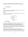
2.7.2. IP Camera
IP Cameras are network devices that connect directly to a HUB. Up to 4 IP Camera can
be connected to one NavNet3D network. At this time, only AXIS IP Cameras
(www.axis.com) that support MPEG4 Video are compatible with NN3D. Certain Axis
PTZ (Pan-Tilt-Zoom) IP Cameras may also be controlled with NN3D Systems for
features such as pan, tilt, and zooming. When connecting an IP Camera to the HUB101,
make sure that the dip switch for Power Synchronization is set to OFF (see 2.6.2 Power
Synchronization for more information)
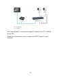
When Power Over Ethernet (POE) AXIS IP cameras are installed (example:
AXIS212PTZ) Furuno recommends utilizing a separate POE Ethernet Switch to provide
power and Ethernet data to each AXIS IP Camera with a single cable. Then, utilize a
non-POE port on this switch to link the IP Cameras to a HUB101 in a NN3D Network.
34
The IP cameras need to have a specific assigned IP address (from 172.31.200.003
through 006).
Please refer to the Appendix “How to configure the AXIS IP Camera” for more
Information
35
2.8.
External Monitors
2.8.1. MFD8/12
A DVI monitor can be connected to the MFD8/12 to repeat the screen at a remote
location. The plug is DVI-D format and only a DVI monitor can be connected.
The MFD8 has a 640x480 (VGA) DVI-D output. The MFD12 has an 800x600 (SVGA)
DVI-D output.
Furuno offers the following DVI cable:
- 5 Meter DVI Cable (FUSA P/N= 000-149-054)
- 10 Meter DVI Cable (FUSA P/N= CBL-DVI-10M)
Please refer to 2.10.1Waterproof Connection when Waterproof is needed
2.8.2. MFDBB
The MFDBB has two DVI-I output ports (Matched Selectable Res from 800x600 up to
1280x1024). The DVI-I output of the MFDBB will “Autosense” the monitors and allow
either DVI monitors or VGA monitors to be plugged in using a “DVI-I-to-VGA adaptor.
Both monitors must be the same type and resolution (VGA or DVI) when using both
ports:
When two monitors are connected to the MFDBB, you can choose to configure the
monitors either in Clone Mode or in Extended Mode.
Note: When two monitors are connected to the MFDBB processor unit, they need to be
capable of displaying the same resolution
36
When Extended Mode is used the two screens need to be located in close proximity to
each other. The two monitors show independent screen displays that can be configured
independently. Only one Keyboard is used to control both monitors (the cursor will
“jump” back and forth from monitor to monitor).
When the two monitors are installed for remote station configuration, dual keyboard
installation from one processor requires use of the Monitor “Clone” mode (in this case
both monitor will show the same picture)
Furuno offers the following DVI cable:
- 5 Meter DVI Cable (FUSA P/N= 000-149-054)
- 10 Meter DVI Cable (FUSA P/N= CBL-DVI-10M)
2.9.
USB and Audio Connection
2.9.1. USB Ports
The MFD8/12 has one USB Ver. 1.0 port and the MFDBB has two USB Ver. 2.0 ports.
These USB ports are used to connect a generic USB mouse and Keyboard. Virtually
any "off the shelf" USB mouse (wired or RF wireless but NOT Bluetooth) will work with
NavNet3D. However, in order to utilize full RotoKey functionality, you will need a mouse
that has a scroll wheel that is also "clickable" with a middle click, which will emulate
selection and confirmation of a desired RotoKey function. No loading of additional
37
mouse software is permitted. However, the standard Mouse HID drivers will load
automatically, allowing most mice and wireless mice to work fine.
Generic USB keyboards may be used to enter Name and Numerical Position. The
Keyboard can also emulate the key of NavNet3D:
USB Keyboard
Action
ESC
CANCEL
F2
SAVE/MOB
F3
DISP
F4
MENU
F5
GAIN/TX
F6
CTRL
F7
DATA/VOL
F8
GO TO/LIST
F9
POINTS/ROUTE
F10
RANGE OUT
F11
RANGE IN
F12
SHIP/3D
Arrows (up, down, left, right)
SCROLLING PAD
Page Up
RotoKey Counter Clockwise
Page Down
RotoKey Clockwise
Enter
Push on RotoKey
End
Power/Brill
Please refer to 2.10.1Waterproof Connection when Waterproof is needed on MFD8/12
38
2.9.2. Audio
Audio In and Audio out are reserved for future Development
Note: If Sirius Satellite Radio control and functionality is desired in the future, be sure to
use the Audio Outputs on the Sirius Receiver (BBWX1) itself and not from an MFD!
2.10.
MFD8/12 Video, USB and Audio Connection
The DVI, USB, Analog Video Input and Audio In/Out ports are behind the connector
cover on the rear panel. To access to the ports and connect the cables, please refer to
the instructions below. Note that these connection points require an optional waterproof
connector boot if necessary. These connection points are not a waterproof design
without this option. Any water egress in this area will not be covered by the limited
warranty.
Note: The Waterproof Connector Boot is only required if the DVI, USB or Audio
connections are used and waterproofing is necessary for the MFD’s location.
2.10.1.
Waterproof Connection
Waterproof connections for the DVI, USB, Analog Video Input and Audio I/O ports
require the optional connector boot (Type: OP19-7, PN: 001-028-090).
Note: This option will not be available until October 2008. Furuno apologizes if this
delay causes any inconvenience with respect to installations
Content of Waterproofing Kit
1. Unfasten the four screws to remove the connector cover at the rear of the display
unit.
39
2. Pass DVI-D, VIDEO, AUDIO and/or USB cables through the fixing plate
(supplied).
3. Attach each connector to the appropriate location at the rear of the display unit.
4. Pass cables through the slit on the boot cover.
5. Install the rubber stopper to each cable. The largest hole is for the DVI-D cable.
40
6. Use the four plate screws (M3x10, supplied) to fasten the fixing plate and boot
cover to the display unit.
7. Slide the rubber stopper into the hole of the rubber boot, and fasten the cable tie
to hold the rubber boot and stopper.
Note: When only the Ethernet, Power, DRS, DATA1, DATA2 and NMEA2000
connection are used the Waterproof Connector boot is not necessary.
41
2.10.2.
Non Waterproof connection
When you do not need waterproofing, use the cable fixing plate (supplied in standard
installation materials).
1. Unfasten the four screws to detach the connector cover at the rear of the display
unit.
2. Attach the cable fixing plate by using the binding screw (M3x10, supplied as the
installation materials).
3. Attach each connector to the appropriate location at the rear of the display unit.
4. Wind the cable tie (supplied as the installation materials) to fix the cables to the
cable fixing plate.
42
3. Configuration
3.1.
Introduction
NavNet3D (just like NavNetVX2) uses Ethernet to share radar/sounder images and
other navigation information from devices connected within a networked system. In any
single NN3D network, a combination of up to ten NavNet3D MFDs may be connected to
each other via Ethernet. All NavNet3D Network Components have an integrated regular
RJ45 Ethernet port for this purpose. Legacy NavNet component such as the ETR-6/10N
(FUSA P/N= BBFF1) or ETR-30N (FUSA P/N= BBFF3) network sounders will need to
be connected using the Hub Adapter Cable 6Pin to RJ45 (FUSA P/N= 000-144-463).
This chapter shows you how to set up your NavNet3D system. Most of the configuration
will be done using the Installation Wizard that is automatically launched during the first
start or can be manually launched by pressing the [MENU] key and selecting “System”
then “Installation Wizard”. Before trying to configure a NN3D system, make sure that
any and all instruments are correctly interfaced. Please refer to the previous chapter
(Wiring) for more information.
On the MFD8/12, the initial configuration is done using the Cursor Pad (upper pad) and
the Center click (which emulate a left click mouse)
On the MFDBB, a generic USB mouse connected to one of the USB port is required
to perform the initial configuration.
Properly designing the NavNet3D network is a key point of a successful installation (see
the Appendix for Installation examples).
43
3.1.1. Selecting a Master
When multiple MFDs are connected in a network, one MFD (and only one) needs to be
designated as the “Master”. The MFD set as Master will act as a “DHCP server” and
automatically performs the network configuration of all the other MFDs in the network.
(The Master sets up the Hostnames, IP addresses etc…).
Note: The notion of “Master” and “Slave” is only an installation setting and is totally
transparent to the end user. In other words, the MFDs set as “Slaves” do not have fewer
features than the “Master”. All MFDs will function and operate similarly.
When choosing the MFD that will be designated as the Master, keep this in mind:
- The Master should be the MFD that will be used primarily (be turned ON all the
time when using the system)
- It is recommended (but not necessary) to have as many instruments as possible
(NMEA0183, NMEA2000) connected directly to the Master.
- When MFD8/12 and MFDBB are used, the MFDBB will be more likely to be
configured as the Master in a given network. (primary MFD)
Note: In a single MFD installation (only one MFD in the network), this MFD must be
configured as the “Master”.
3.1.2. Data Source Selection
In a network installation (and even in a standalone system), multiple sensors can
provide the same information (i.e.: Sounder and Smart Sensor can both provide depth
information). NavNet3D allows you to select, for each type of data (Position, Depth,
Temperature, Heading…), the sensor that will be used as a primary source.
In addition, if the primary sensor fails and if another sensor providing the same
information is detected on the network, NavNet3D will automatically switch to the other
source after giving you an alert.
3.1.3. Installation Wizard Conceptual Description
The Installation Wizard is divided into sections (Tabs) that are targeted to configure
specific aspects of the system:
44
“Own Setting” Tab
This Tab configures the local ports of the MFD (NMEA0183 Input/Output, NMEA2000
Output) on which the Installation Wizard is currently used.
This is also where the Master can be designated (DHCP Server turned ON)
“Global” Tab
This Tab contains configuration information that is global to the system and shared
among MFDs.
This is the section where the Data Source (Sensors) can be selected to be used as
primary information. You will be able to customize sensor names (ex. Assign Location
Nicknames) that will help you configure the system.
This Tab will also allow you to enter vessel’s specifications (size, Motor configuration…)
Note: It is recommended to perform the Global Configuration from the MFD set up as
Master
“Sounder” Tab
When a Network Sounder is detected, this Tab will appear and allow you to configure
your sounder module. NavNet3D is compatible with the Airmar Transducer ID protocol.
This feature enables compatible transducers to transmit important data to the DFF1 or
DFF3, including transducer model, functions, frequency, power rating, beam pattern,
impedance, ceramic element configuration and acoustic window material. Through this
Transducer ID feature, the DFF1 and DFF3 Sounder Modules will automatically know
the connected transducer’s precise frequency, operating power and impedance, so it
can “tune” its operation to automatically adjust and optimize echo sounder performance.
“Radar” Tab
When a DRS (Radar) is detected, this Tab will appear and allow you to configure your
Radar and perform the Heading Alignment adjustment.
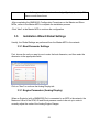
3.2.
Installation Wizard Own Settings
-Press the power switch of the MFD you want to designate as Master to power it ON.
After few minutes, the Installation Wizard starts.
Note: The start up time of NavNet3D will be shorter once the system is fully configured.
45
-The system will search for sensors on the network. Allow the system to fully perform
the search (which takes about 30 seconds). Do not click the Skip button.
-After the detection, the language selection screen appears. The default language is
English. Use the Cursor Pad and the center click (or the mouse for the MFDBB) then
click on “Next:
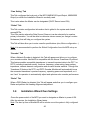
3.2.1. Own Settings (Master, Power Synchronization, Monitor)
To set up an MFD as a Master, just set the “DHCP server setting” as “Enable”.
Set the “Power synchronization” to enable if you want to use this feature.
46
Note: Power Synchronization requires a HUB101 and proper hardware configuration.
Please refer to 2.6.2
Power Synchronization paragraph for more Information
Note: On the MFDBB, the same page allows you to select the monitor resolution and
the Dual Screen mode configuration (when two monitors are used).
Leave the DVI Resolution to “AUTO” (this default setting will work for most installation
configurations).
Please refer to 2.8.2
47
External Monitor for more information on Clone and Extended mode when two monitors
are connected to a single MFDBB processor.
After enabling the DHCP server click on “Exit” to validate the setting.
The MFD will Power OFF automatically!
Power ON the “Master” MFD. Wait a few minutes until the Installation Wizard appears
on the Master then power ON all the other MFDs in the network and continue the
Installation Wizard configuration on the Master MFD.
Click on “Next” on the Master MFD to continue the configuration.
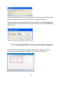
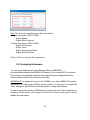
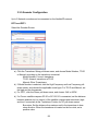
3.2.2. NMEA2000 Data Configuration
This page configures the information that the MFD will output on its own NMEA2000
port. The information embedded in the PGN will be the information coming from the
Sensor that will be chosen as the Primary Source (see next paragraph). Enable each
NMEA2000 Data PGN that will be sent through the individual MFD’s NMEA2000 port.
Note that in a multi-MFD network, each MFD’s NMEA2000 backbone is separate and
independent. Therefore, you may have to perform the same procedure on each MFD
where external NMEA2000 displays (ie. FI-50, etc...) or sensors are connected.
Note: This setting only configures the NMEA2000 Output Data. The NMEA2000 data
received (Input) at each MFD and DRS is global and automatically recognized by the
network. Each NMEA2000 Data Source at each MFD will automatically appear and
may be selected as a Primary System Data Source.
48
Click on the “Next” button to continue the configuration.
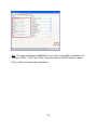
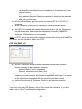
3.2.3. NMEA0183
The three “NMEA0183 Port” tabs are used to configure the Input and Output of the
individual MFD’s own NMEA0183 ports. It is important to understand that it is not
possible to filter any received NMEA0183 Data at any of these ports on individual
MFDs. And unlike the automatic recognition capability with NMEA2000 Data sources, it
is instead necessary to manually specify or declare the specific type of NMEA0183
sensor that is interfaced to the each NMEA0183 Input Port.
In these Tabs, you will have to configure the NMEA0183 Output Port specification
(Version, Baud rate…) and the sentences needed to be output.
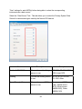
Note: “WPT ID Format” allows you to select if the name of the WPT or the WPT
sequence number is transmitted to an Autopilot.
The “L/L format” dialog box, allows you to choose how many digits (seconds) to display
after the decimal point in latitude and longitude of the position sentences.
Next, you must declare the type of NMEA sensor(s) connected to the corresponding
NMEA0183 Input Ports on the Master MFD. This information will be used in the Global
Data Source Tab for selecting the Primary System Data Sources.
49
IMPORTANT!: After configuring any NMEA0183 Input Port Sensors on the Master
MFD, you must REPEAT THIS PROCEDURE at any other Slave MFDs in the network
where you have connected NMEA0183 Input Sensors!! If this is not done, the sensors
will not be available for selection as a Primary System Data Source in the Global
Settings Tab.
Example: If you connect a sensor such as a PB100 which provides Wind information but
also Position, you will have to check “Position & SOG/COG” as well as “Wind”
When you connect a GP320B (FUSA P/N= BBWGPS) to NMEA Port 1, a “Page 2”
automatically appears in the lower right corner of the page. Click on this button to
configure advanced settings of the GP320B.
Name
Description
POS.
Smoothing
When the receiving condition is unfavorable, the GPS fix may change,
even if the vessel is stopped. This change can be reduced by smoothing
50
the raw GPS fixes. A setting between 000 to 999 is available. The higher
setting the more smoothed the raw data, however too high a setting
slows response time to change in latitude and longitude. This is
especially noticeable at high ship’s speeds. Increase the setting if the
GPS fix changes.
SOG/COG
Smoothing
During position fixing, ship’s velocity (speed and course) is directly
measured by receiving GPS satellite signals. The raw velocity data may
change randomly depending on receiving conditions and other factors.
You can reduce this random variation by increasing the smoothing. Like
with latitude and longitude smoothing, the higher the speed and course
smoothing the more smoothed the raw data. If the setting is too high,
however, the response to speed and course change slows. For no
smoothing, enter all zeroes.
Disable
Satellite
Every GPS satellite is broadcasting abnormal satellite number(s) in its
Almanac, which contains general orbital data about all GPS satellites,
including those which are malfunctioning. Using this information, the
GPS receiver automatically eliminates any malfunctioning satellite from
the GPS satellite schedule. However, the Almanac sometimes may not
contain this information. If you hear about a malfunctioning satellite from
another source, you can disable it manually. Enter satellite number
(max. 3 satellites) in two digits.
INIT.
Position
Set initial latitude/longitude position for cold start.
ANT.
Position
Enter the GPS antenna positioning bow-stern and port-starboard
position.
ANT. Height
Rx Mode
WAAS Mode
WAAS
Search
Enter the height of the GPS antenna unit above sea surface.
Choose position fixing method: 2D (three satellites in view), 2D/3D
(three or four satellites in view whichever is greater).
Select ON to use the WAAS mode.
WAAS satellite can be searched automatically or manually. For manual
search, enter appropriate WAAS satellite number.
WAAS Alarm When the WAAS signal is lost, the audible alarm sounds one of two
ways. On: Alarm sounds continuously until the WAAS positioning mode
51
is available again or the alarm is acknowledged (by key operation). Off:
Alarm sounds three times.
-After completing the NMEA0183 Configuration Procedures on the Master and Slave
MFDs, return to the Master MFD to complete the installation process.
-Click “Next” at the Master MFD to continue the configuration
3.3.
Installation Wizard Global Settings
Usually, the Global Settings are performed from the Master MFD in the network
3.3.1. Boat Parameter Settings
First, choose the unit you want to use to enter the boat dimension, and then enter the
dimension in the appropriate fields.
Click on “Next” to continue the Analog Display tab
3.3.1. Engine Parameters (Analog Display)
When an Engine(s) with a NMEA2000 Port is connected to an MFD in the network, the
Maximum Value of the RPM, Oil and Boost pressure needs to be set up in order to
correctly adjust the scale of the Analog Engine Gauges.
52
Note: The currently accepted engine data is as follows:
- Engine Parameters (PGN 127488)
Engine Speed
Engine Boost Pressure
- Engine Parameters (PGN 127489)
Engine Oil Pressure
Engine Temp
Engine Temperature Status
Engine Warning Status
Click on “Next” to continue the configuration
3.3.2. Assigning Nicknames
You can assign Nicknames to every Ethernet Sensor, NMEA2000
instrument/sensor/display and NMEA0183 Receive Port for every MFD in a network.
This will help you remember locations and assign the sensors designated as the
Primary System Data Source during the next step.
IMPORTANT!: As explained in section 3.2.3 NMEA, if you have NMEA0183 sensors
connected to the input ports of MFD(s) on the network, you first need to configure the
“Own” settings for each MFD(s) before being able to assign Niccknames.
In order to enter new names, a USB keyboard needs to be used. After assigning new
names on the left column, don’t forget to push the “Set” button (lower right) in order to
validate the new names.
53
Note: This page will display the NMEA0183 Input Ports of every MFD connected to the
network as “Port1”, “Port2” and “Port3”. Each port refers to the MFD listed just above.
Click on “Next” to continue the configuration
54
3.3.3. Camera Names
You can assign names to each connected Analog and IP Camera. These names will be
used by the RotoKey and for the Video ID in the main interface.
The IP Camera names are Global and only need to be configured at the Master MFD.
However, the Analog cameras must be named at each MFD where they are connected.
Please refer to the Appendix “How to configure the AXIS IP Camera” for more
information.
Note: “PnP” refers to the Analog Connection (Picture in Picture). Four PnP are available
on the MFDBB and two on the MFD8/12.
Click on “Next” to continue the configuration
3.3.4. Primary Data Source selection
IMPORTANT!: As explained in section 3.2.3 NMEA, if you have NMEA0183 sensors
connected to the input ports of MFD(s) on the network, you first need to configure the
55
“Own” settings for each MFD(s) before being able to select the corresponding
instruments as a data source.
Select the “Data Source” Tab. This tab allows you to select the Primary System Data
Source for various data types used by the Navnet 3D Network.
Name
Description
Example
Position & SOG/COG
Choose the position-fixing
sensor to use.
GP-320B, GP-330, NMEA
2000 format GPS
Heading
Choose the heading sensor
to use
SC-30, SC-50, PG-500,
PG-1000, Other
Speed Through Water
Choose the speed (STW)
sensor to use.
Smart sensor (NMEA
0183), Speed sensor
(ETR), Smart sensor
(NMEA 2000), Other
(NMEA 0183)
56
Water Depth
Choose the depth sensor to
use.
Smart sensor (NMEA
0183), Speed sensor
(ETR), Smart sensor
(NMEA 2000), Other
(NMEA 0183)
Water Temperature
Choose the temperature
sensor to use.
Smart sensor (NMEA
0183), Speed sensor
(ETR), Smart sensor
(NMEA 2000), Other
(NMEA0183)
Wind
Choose the wind sensor to
use.
FI-501/502, PB-100, WS200, PB-200, Other
Date & Time
Choose the date and time
source to use.
GP-320B, GP-310B, SC30, NMEA 2000 format
GPS, Other
Roll and Pitch
Choose the motion sensor
to use.
SC-30, SC-50, WS-200,
PB-200, Other
AIS
Choose the AIS equipment
to use
FA-150, FA-30, FA-50,
Other
Note: If a NMEA0183 Instruments does not appear as selection, make sure that the
Input Type was correctly connected and assigned at each MFD. Please refer to 3.2.3
NMEA0183.
-If you don’t have any DRS (Radar) and Network sounder click on Exit to finish the
installation. If you have a radar or sounder, click on “Next” to continue the configuration.
57
3.3.5. Sounder Configuration
Up to 2 Network sounders can be connected on the NavNet3D network.
DFF1 and DFF3
Select the Sounder Source:
a) Click the Transducer Setup pull-down menu, and choose Model Number, TD-ID
or Manual, according to the transducer connected.
Model Number: Furuno’s transducer
TD-ID: Airmar’s transducer w/TD-ID
Manual: Other Transducers
b) If Model Number is selected, click the High Frequency and Low Frequency pulldown menus, and choose the applicable model type. For TD-ID and Manual, set
the high and low frequencies.
c) For DFF1, click the Power pull-down menu, and choose 1kW or 600W
d) If a Furuno satellite compass SC-30 or SC-50/110 is connected, set the distance
between antenna unit (or sensor) of the satellite compass and transducer (high
and low if connected) at the Transducer Position for SC pull-down menus.
Bow-stern: Set the distance from antenna unit to the transducer in bowstern direction. When the transducer is located on the fore side, set a
positive value.
58
Up-down: Set the distance from the transducer to the antenna unit in the
vertical direction.
Port-starboard: Set the distance from antenna unit to the transducer in
port-starboard direction. When the transducer is located on the starboard
side, set a positive value.
e) Click the Motion Sensor pull-down menu, and choose SC-30 or SC-50/110 if
connected.
f) Set the transducer position at the Transducer Position pull-down menus.
g) If the DFF3 is equipped with a water temperature sensor, click the Temperature
Port pull-down menu, and choose the temperature source, MJ (NMEA0183
connector), High-frequency or Low-frequency.
Note: For DFF3, set the tap setting in the network sounder after setting up all the MFDs.
For details, see the Operator’s Manual for DFF3.
ETR 30/60 (BBFF1/3)
a) Click the Transducer Setup pull-down menu, and choose Model Number or
Manual, according to the transducer connected.
Model Number: Furuno’s transducer
Manual: Transducers other than Furuno
b) If you choose Model Number at step a), click the High Frequency and Low
Frequency pull-down menus, and choose the applicable model type. For Manual,
set the high and low frequencies with the respective pull-down menus.
c) Use the arrow buttons at Transducer Position to set transducer position.
d) If a radar sensor is connected, click the Next button to continue.
If you don’t have any DRS (Radar), click on Exit to finish the installation. If you have
radar, click on “Next” to continue the configuration.
59
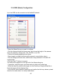
3.3.6. DRS (Radar) Configuration
Up to two DRS can be connected on the NavNet3D network.
- Select the Radar Source you want to configure
- Click the Antenna Height pull-down menu, and choose the height of the antenna
above the waterline, among under 10ft, 10ft-30ft or over 30ft.
- Perform the heading adjustment as follows.
- Steer towards a suitable visible target(for example, moored ship or buoy).
- Click the Range pull-down menu, and choose a range between 0.125 and 0.25
nautical miles.
- Click the Push TX button to transmit.
The radar picture appears on the right-half of the Radar dialog box.
- If necessary, adjust the gain, sea clutter and rain clutter using slider bars.
- While the vessel is pointed at the target, turn the RotoKey or drag the Slide Bar to
bisect the target with the displayed line.
- As a final test, steer towards a small buoy and confirm that the buoy shows up dead
ahead on the radar when it is visually dead ahead.
60
- Click the Push STBY button to stop the transmission.
Click on “Exit”. This will close the Installation Wizard and launch NN3D
When the Agreement appears on the display, push RotoKey to agree.
Important: If you are using a MFDBB, the Keyboard will not work until it is properly
“Linked” to a processor unit. Please refer to 3.4
61
MFDBB Keyboard/Processor Linking then continue to the next paragraph to finish the
Radar Installation.
When the MFD displays the main interface, push the [MENU] key. Use the RotoKey to
scroll to the “Radar” page. Use the Cursor Pad or the mouse and click on “Radar
Source” to select the DRS you want to use.
Press the [MENU] key to close the Menu then press the [DISP] key. Use the RotoKey to
select a Radar screen and push to validate the selection.
Push the [GAIN/TX] key to transmit and make sure that a Radar picture appears on the
screen.
As a final step, you will have to enter the “Service Man Mode” to perform the Main Bang
Adjustment and the Automatic Radar Optimization procedure.
Enter Service Man Mode - Press and hold the [CTRL] key and push the [MENU] key.
This will allow access to the “Service Man” advanced settings.
Use the Cursor Pad or a mouse then click on.
Radar Optimization
Click on “Radar Optimization” and wait for the confirmation window to appear.
Main Bang Adjustment
Main bang is the “black hole” which appears at the display center on short ranges.
Select “MBS Adjustment” and rotate the RotoKey to suppress the main bang. After
adjusting, push the RotoKey to validate.
Press the [MENU] key to close the Menu.
62
3.4.
MFDBB Keyboard/Processor Linking
MFDBB Keyboards are Ethernet network devices that need to be assigned (linked) to a
specific MFDBB processor unit during installation. A special “key-push” sequence is
used to cycle through the “Linking Codes” for all the MFDBB processor unit(s).
If only one MFDBB processor unit is on the Network:
Simultaneously press and hold the Left key of the Scrolling Pad, the Right key of the
Cursor pad and push the RotoKey for 5sec. (This intentionally requires two hands)
The Keyboard will beep two times. You can release the button at this time. The
keyboard will now control the MFDBB.
Note: If this process fails, make sure that one MFD is set as Master on the network.
Disconnect and reconnect the keyboard from the processor unit and try again.
If multiple MFDBB Processor Units are on the Network:
Make sure that all MFDBBs are ON and are displaying the Main Interface (or the
Agreement Box). Repeat the process (as explained above) until two beeps are heard.
Try to push the RotoKey and/or use the scrolling pad to see if the MFDBB you are
looking to can be controlled with the current keyboard.
If the MFDBB does not respond (This means that the keyboard is actually linked to
another processor unit on the network), repeat the process until the keyboard controls
the correct MFDBB processor.
Repeat this process to link the other MFDBBs to their Keyboards.
63
4. Registering the System
4.1.
SystemID Description
The Navnet 3D SystemID is a unique number assigned to a complete NN3D networked
system with one or more MFDs. On the same boat, all networked MFDs have the same
SystemID. This number will not change if a MFD or other NavNet Component is added
to the system. The SystemID is used to identify the customer when he purchases data
or services. Note that the unique SystemID will be created automatically only when the
system is set-up (when all MFD are networked together and one Master is assigned).
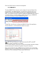
To access the SystemID, press the [MENU] key on any MFD, turn the RotoKey to select
the “My NavNet” page. The SystemID is the 20 digit number (beginning by “SI”) at the
bottom of the page.
It is highly recommended to immediately write down the SystemID on the Furuno
Registration Card.
4.2.
Registration Card
A registration Card comes with every MFD. This Registration Card contains the Serial
Number and the Registration Number that are required to correctly register the system
online at www.navnet.com. Note that customers will not be able to update embedded
charts or purchase additional data if the System is not properly registered online.
In order to register, the customer will need to enter the Registration Number of each
MFD. It is also recommended to enter the SystemID at the time of registration
64
5. Appendix
5.1.
Example NN3D System Configurations
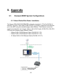
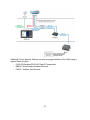
5.1.1. Basic Plotter/Fish Finder Installation
The Furuno GPS (FUSA P/N BBWGPS) is directly connected to 7-Pin Port DATA1 of
the MFD. The DFF1 Fish Finder (FUSA P/N DFF1) is directly connected to the Ethernet
port of the MFD using the standard supply cable (3Meter). If the Ethernet connection
needs to be extended, use a longer cable or add a LAN Coupler (FUSA P/N= RJ4-5CNSTR) with the following longer Ethernet Cables:
- 2 Meter RJ45 to RJ45 Ethernet Cable (P/N 000-167-175)
- 5 Meter RJ45 to RJ45 Ethernet Cable (P/N 000-167-176)
- 10 Meter RJ45 to RJ45 Ethernet Cable (P/N 000-167-177)
65
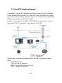
5.1.2. Basic Plotter/Radar/Fish Finder Installation
This is a single station Plotter/Radar/Fish Finder installation.
The Furuno GPS (FUSA P/N BBWGPS) is directly connected to 7-Pin Port DATA1 of
the MFD. Since two Ethernet sensor are on the network (DRS Radar and Fish Finder),
a network switch (FUSA P/N HUB101) is necessary. In this case the Radar Power
Cable is directly connected to the back of the MFD8/12 (DRSxD (Domes) can be
powered directly by any MFD. For DRSxA (Open) check compatibility). The Ethernet
side of the DRS Siamese cable may be extended using a coupler (FUSA P/N= RJ45CN-STR) and an Ethernet cable.
Optional Ethernet Cables that can be used:
- 2 Meter RJ45 to RJ45 Ethernet Cable (P/N 000-167-175)
- 5 Meter RJ45 to RJ45 Ethernet Cable (P/N 000-167-176)
- 10 Meter RJ45 to RJ45 Ethernet Cable (P/N 000-167-177)
-Note that the HUB101 and all MFDs have “AUTO MDX” Ethernet Ports. This means
that they will automatically adjust for straight and cross-over Ethernet cables!
-Note that this installation will not allow Radar Overlay or ARPA target acquisition. If
these functions are desired, a Heading Compass sensor such as the Furuno
PG500/SC30/SC50 is required (see next installation example)
66
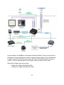
Additional Furuno Network Sensors can also be plugged directly to the HUB (using a
regular Ethernet cable):
- FA30 AIS Receiver/FA50 AIS Class B Transponder
- BBWX1 Sirius Satellite Weather Receiver
- FAX30 - Weather Fax Receiver
67
5.1.3. Dual MFD Installation Example
This installation is a dual MFD installation with Radar Overlay and ARPA functionality
(PG500 Heading Sensor included). The Furuno GPS (FUSA P/N BBWGPS) is directly
connected to 7-Pin Port DATA1 of the MFD. The Furuno Heading Compass (FUSA P/N
PG500) is connected to port DATA2 of the MFD.
Note that in this installation, the DRS is a 12kW “DRS12A” and therefore an optional
power supply (PSU12) is required to supply power to the DRS12.
Additional sensor can also be plugged directly to the HUB (using regular Ethernet
cable):
- FA30 AIS Receiver
- FA50 AIS Class B Transponder
- BBWX1 Sirius Satellite Weather Receiver
- FAX30 - Weather Fax Receiver
68
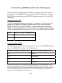
5.1.4. Dual Screen MFDBB Installation with Pilot Integration
Navpilot 500 Series Integration with NN3D MFDs is similar to Navnet vx2 integration.
One difference is that NN3D MFDs no longer have an AD10 Heading Port. However,
NN3D MFDs do require high speed NMEA0183 heading information (10Hz) for ARPA
functionality.
Heading Interface to MFD:
To meet the High Speed Heading requirement, it is necessary to directly connect the
output from the NMEA Port (Middle Connector) on the PG500 to one of the three
NMEA0183 Receive Ports on a NN3D MFD. It is easy to make this connection by
cutting and splicing the standard 6 pin-to-6 pin cable, that is supplied standard with the
PG500, to either NMEA0183 Receive Port 2 or Port 3 on the DATA2 Cable of an MFD:
PG500
MFD DATA2 Pig Tail (NMEA Port3)
White
Blue
Black
Blue/White
Nav Data Interface to MFD:
The Nav Data connection to the Navpilot processor from one of the NMEA0183 Output
Ports of the NN3D MFD is similar to that of Navnet vx2:
Navpilot Processor TB7 (NMEA In/Out)
MFD DATA2 Pig Tail (NMEA Port2)
Pin 1*
Brown
Pin 2*
Brown/White
Pin 3
Red
Pin 4
Red/White
*Note that this connection is only necessary if Rudder Angle Information is needed because an FI-50
series FI-506 Rudder Display is used on an MFD NMEA 2000 Backbone. In this case, make sure that
ONLY the "RSA" Sentence is turned on from the software of the Navpilot System. If Rudder Angle is not
needed, the receive port may alternatively be used to bring in the Heading Data from the PG500 or
connection to another NMEA0183 transmitting device.
69
In this example, the MFDBB is configured for Extended Mode. The two monitors show
independent screen displays that can be configured independently. Only one Keyboard
is used to control both monitors (the cursor will “jump” back and forth from monitor to
monitor). The two screens need to be located in close proximity to each other.
Optional DVI Cables that can be used:
- 5 Meter DVI Cable (P/N 000-149-054)
- 10 Meter DVI Cable (P/N CBL-DVI-10M)
70
5.2.
Configuring AXIS IP Cameras
5.2.1. Introduction:
In order to view and control Axis IP Cameras from an MFD in a Navnet 3D network, it is
first necessary to assign the IP Address of a MPEG-4 capable AXIS IP Camera. This
procedure will require a Windows PC connected via Ethernet to the AXIS IP Camera(s).
Pre-wiring and installing the cameras on the vessel first is recommended so that all
AXIS IP cameras can be networked to the PC through a Hub and can be configured at
the same time. It will be necessary to setup the IP Address of the PC and use the AXIS
IP Utility Program (Provided with the Camera) to configure the Camera’s IP Address.
5.2.2. Setting the IP of the computer
Go to “Start” and select “Control Panel”
Open “Network Connections”
71
Right Click on “Local Area Connection” and select “Properties”
Select “Internet Protocol (TCP/IP)” and click on “Properties”
Fill the IP fields as shown below.
Click on OK to confirm and close the 2 windows.
72
Note that the new IP can take up to 20 seconds to be recognized. A pop-up in the lower
right corner should show when the IP is correctly set. Turn OFF any Firewall that could
prevent data to be exchanged between NavNet and the PC. You may also have to
restart your computer.
5.2.3. Set up the IP address of the camera
To work with NavNet3D, the IP cameras need to be set up with specific IP Addresses.
Up to 4 IP cameras can be connected on a network.
IP Camera number 1 = 172.031.200.003
IP Camera number 2 = 172.031.200.004
IP Camera number 3 = 172.031.200.005
IP Camera number 4 = 172.031.200.006
In this example, we will set up 3 IP cameras:
-
A moving IP camera (AXIS 212PTZ) that will be configured as IP Camera 1
A non moving IP Camera (AXIS 207) that will be configured as IP Camera 2
A non moving IP Camera (AXIS 207) that will be configured as IP Camera 3
Load the AXIS CD “Network Video Products” that was including with the IP camera. The
Autorun software should appear.
(If the autorun is not working on your computer, browse the CD and double click on
“Setup”)
Select “Install Product”
73
Click on “Copy to PC”
The following window should appear. Just double click on “IPUtility” to launch the
configuration software
Note: If the Windows Firewall appears, click on “Unblock” to allow the software to
configure correctly the IP Camera
74
The AXIS IP utility will detect all the IP cameras connected on the network
Note: If you use the same camera models in multiple locations, BE SURE to WRITE
DOWN the IP Camera serial number (that can be found on the back of the camera) with
the intended location to help correctly assign the IP camera’s name.
In this example, we will assign a moving camera (212 PTZ) to IP Camera 1 (Deck), a
non-moving camera with the SN ending with 34CB to IP Camera 2 (Engine Port) and a
non-moving camera with the SN ending with 3441 to IP Camera 3 (Engine Starboard).
To change the IP address of the Camera, just select the camera in the list and click on
the “assign new IP address to selected device” button
Enter the correct IP address and click on “Assign”
75
You will need to restart (power OFF and ON) the camera after the address is changed.
(Just unplug and plug back the Ethernet cable if you are using the POE).
It can take a while before the confirmation box appears.
Click the “Close” button.
The first IP camera has been correctly assigned
Repeat the process with the other cameras
76
5.2.4. Configure the camera
The cameras need to be configured using a Internet Explorer.
Enter the IP address of the first IP camera:
Set the password of the IP camera to “pass” and click “OK”
Important: You cannot use another password and must use the word “pass”.
When you press OK, a dialog box asking for a login/password will appear. Just use
“root” and “pass”.
77
When the webpage loads, pay attention to the top of the page to authorize the
installation of the ActiveX. Click on the yellow bar and choose “Install ActiveX”
At this point a camera image should appear
Now, click on Setup
78
1) In “Basic Configuration -> Users” select “Enable anonymous viewer…” and click
on “Save”
2) In “Basic Configuration -> Date and Time” select “Synchronize with computer
time” and click on “Save”
3) In “Live View Config -> Layout” select “MPEG4” as the default video format and
click on save
4) Optional: When using a PTZ (moving) camera, you can set-up the default
“Home” position. In “PTZ configuration -> Preset Positions”, adjust the view of the
default camera position using the control
Note: It is recommended to zoom in on the image (Tele) to have a better “Home” preset.
79
When the view is correctly set up, type “Home” for the Current position and select “Use
current position as Home”. Click on “Add” to validate.
If you don’t want the camera to return to the “Home” position automatically after 30 sec,
just put 0 and validate.
80
UNIT
001-028-050-00
CP19-00901
000-157-995-10
MJ-A3SPF0017-050ZC
000-164-608-10
FRUDD-18AFFM-L180
000-164-609-10
**
1
1
1
Q'TY
1
1
1
1
CP19-00900
MOD-WPAS0001-030+
001-023-060-00
FP19-01101
001-028-020-00
SP19-00701
000-011-776-00
MFD8-J/E
DESCRIPTION/CODE №
MFD8-J/E
(略図の寸法は、参考値です。 DIMENSIONS IN DRAWING FOR REFERENCE ONLY.)
2.(*1)は、それぞれ仕様選択品を表します。
(*1)INDICATE SPECIFICATION SELECTIVE ITEM.
1.コ-ド番号末尾の[**]は、選択品の代表コードを表します。
CODE NUMBER ENDING WITH "**" INDICATES THE CODE NUMBER OF REPRESENTATIVE MATERIAL.
INSTALLATION MATERIALS
工事材料
CABLE ASSY.
ケーブル組品MJ
CABLE ASSEMBLY
ケーブル組品
OUTLINE
INSTALLATION MATERIALS
ACCESSORIES
SPARE PARTS
LAN CABLE ASSEMBLY
ケーブル組品LAN
工事材料
ACCESSORIES
付属品
付属品
SPARE PARTS
予備品
予備品
MULTI FUNCTION DISPLAY
マルチファンクションディスプレイ
ユニット
NAME
PACKING LIST
DOCUMENT
OUTLINE
1/1
000-167-814-1*
OM*-44441-*
000-167-803-1*
OSJ-44440-*
000-167-805-1*
MLG-44440-*
000-167-806-1*
IM*-44440-*
000-167-809-1*
C42-00706-*
000-167-941-1*
C42-00709-* ワ/エイ
000-167-721-1*
1
(*1)
1
(*1)
1
1
1
1
1
1
Q'TY
TWO TYPES AND CODES MAY BE LISTED FOR AN ITEM. THE LOWER PRODUCT MAY BE SHIPPED IN PLACE OF
THE UPPER PRODUCT. QUALITY IS THE SAME.
19BA-X-9851
型式/コード番号が2段の場合、下段より上段に代わる過渡期品であり、どちらかが入っています。 なお、品質は変わりません。
**
**
NAVNET3 O/M *CD-ROM*
000-168-580-10
H293XW230XT18
DESCRIPTION/CODE №
3.付属品及び一部の図書は、書類ケースに収められています。
ACCESSORIES AND A PART OF THE DOCUMENTS IS PUT IN THE DOCUMENTS CASE.
OPERATOR'S MANUAL
取扱説明書
OPERATOR'S GUIDE
操作要領書(和)
OPERATOR'S GUIDE
操作要領書(タゲン)
INSTALLATION MANUAL
装備要領書
NOTIFICATION DOCUMENT
ヒューズ変更のお願い ワ/エイ
FLUSH MOUNTING TEMPLATE
フラッシュマウント型紙
OPERATOR'S MANUAL CD
取扱説明CD
DOCUMENTS CASE
書類ケース
図書
NAME
19BA-X-9851 -4
A-1
UNIT
001-028-060-00
CP19-01001
000-153-769-11
MJ-A3SPF0027-050ZC
000-164-608-10
FRUDD-18AFFM-L180
000-164-609-10
**
1
1
1
Q'TY
1
1
1
1
CP19-01000
MOD-WPAS0001-030+
001-023-060-00
FP19-01101
001-028-030-00
SP19-00801
000-011-778-00
MFD12-J/E
DESCRIPTION/CODE №
MFD12-J/E
(略図の寸法は、参考値です。 DIMENSIONS IN DRAWING FOR REFERENCE ONLY.)
2.(*1)は、仕様選択品を表します。
(*1)INDICATE SPECIFICATION SELECTIVE ITEM.
1.コ-ド番号末尾の[**]は、選択品の代表コードを表します。
CODE NUMBER ENDING WITH "**" INDICATES THE CODE NUMBER OF REPRESENTATIVE MATERIAL.
INSTALLATION MATERIALS
工事材料
CABLE ASSEMBLY
ケーブル組品MJ
CABLE ASSEMBLY
ケーブル組品
OUTLINE
INSTALLATION MATERIALS
ACCESSORIES
SPARE PARTS
LAN CABLE ASSEMBLY
ケーブル組品LAN
工事材料
ACCESSORIES
付属品
付属品
SPARE PARTS
予備品
予備品
MULTI FUNCTION DISPLAY
マルチファンクションディスプレイ
ユニット
NAME
PACKING LIST
DOCUMENT
OUTLINE
1/1
000-167-224-1*
C42-00704-* ワ/エイ
000-167-814-1*
OM*-44441-*
000-167-803-1*
OSJ-44440-*
000-167-805-1*
MLG-44440-*
000-167-806-1*
IM*-44440-*
000-167-809-1*
C42-00706-*
000-167-721-1*
1
1
(*1)
1
(*1)
1
1
1
1
1
Q'TY
TWO TYPES AND CODES MAY BE LISTED FOR AN ITEM. THE LOWER PRODUCT MAY BE SHIPPED IN PLACE OF
THE UPPER PRODUCT. QUALITY IS THE SAME.
19BA-X-9852
型式/コード番号が2段の場合、下段より上段に代わる過渡期品であり、どちらかが入っています。 なお、品質は変わりません。
**
**
NAVNET3 O/M *CD-ROM*
000-168-580-10
H293XW230XT18
DESCRIPTION/CODE №
3.付属品及び一部の図書は、書類ケースに収められています。
ACCESSORIES AND A PART OF THE DOCUMENTS IS PUT IN THE DOCUMENTS CASE.
FLUSH MOUNTING TEMPLATE
フラッシュマウント型紙
OPERATOR'S MANUAL
取扱説明書
OPERATOR'S GUIDE
操作要領書(和)
OPERATOR'S GUIDE
操作要領書(タゲン)
INSTALLATION MANUAL
装備要領書
NOTIFICATION DOCUMENT
ヒューズ変更のお願い ワ/エイ
OPERATOR'S MANUAL CD
取扱説明CD
DOCUMENTS CASE
書類ケース
図書
NAME
19BA-X-9852 -5
A-2
ᢙ㊂
36;
↪ㅜ㧛⠨
4'/#4-5
⇟ภ
01
$+0&+0)*'#&5%4'9
㩔㩨㨼㩧㩎㩨ዊ㩒㩆㩨
%#$.'ޓ6+'
㩄㩧㩗㩨㨹㩂㩇
5'.(6#22+0)5%4'9
㩎㩡㩇㩊㨹㩕㩩㩧㩒㩆㩨ޓ㩆㨷
%#$.'(+:+0)2.#6'
㩃㨺㩖㩨㩣ᜬ㊄ౕ
(75'.#$'.
㩕㨷㨺㩇㩨㩔㩢㩙㨺㩂
/1706+0)5210)'
(㩙㨽㩧㩎㩠㨽㩇㩘㩩㩧㩆㩨
ฬޓޓ⒓
0#/'
/(&
⇛ޓޓ࿑
176.+0'
%1&'01
/:575
%1&'01
%8$
%1&'01
:575
%1&'01
%1&'01
%1&'01
ဳฬ㧛ⷙᩰ
&'5%4+26+105
%2
ᢙ㊂
36;
↪ㅜ㧛⠨
4'/#4-5
$#: 㧲㨁㧾㨁㧺㧻ޓ㧱㧸㧱㧯㨀㧾㧵㧯ޓ㧯㧻ޓ㧚㧘㧸㨀㧰
㧔⇛࿑ߩኸᴺߪޔෳ⠨୯ߢߔ&ޓޕ+/'05+105+0&4#9+0)(144'('4'0%'10.;㧕
$#:
㧲㨁㧾㨁㧺㧻ޓ㧱㧸㧱㧯㨀㧾㧵㧯ޓ㧯㧻ޓ㧚㧘㧸㨀㧰
㧔⇛࿑ߩኸᴺߪޔෳ⠨୯ߢߔ&ޓޕ+/'05+105+0&4#9+0)(144'('4'0%'10.;㧕
$#:
6916;2'5#0&%1&'5/#;$'.+56'&(14#0+6'/6*'.19'4241&7%6/#;$'5*+22'&+02.#%'1(6*'722'4241&7%6
37#.+6;+56*'5#/'
%1&'01
/:575
%1&'01
%8$
%1&'01
:575
%1&'01
%1&'01
%1&'01
ဳฬ㧛ⷙᩰ
&'5%4+26+105
+056#..#6+10/#6'4+#.5
Ꮏ᧚ᢱ
/7.6+(70%6+10&+52.#;
6;2'
%1&'01
ဳᑼ㩄㨺㩎㩨⇟ภ߇㧞Ბߩ႐วޔਅᲑࠃࠅᲑߦઍࠊࠆㆊᷰᦼຠߢࠅޔ߅ߥޓޕߔ߹ߡߞ߇߆ࠄߜߤޔຠ⾰ߪᄌࠊࠅ߹ߖࠎޕ
⇛ޓޓ࿑
176.+0'
$#: 6916;2'5#0&%1&'5/#;$'.+56'&(14#0+6'/6*'.19'4241&7%6/#;$'5*+22'&+02.#%'1(6*'722'4241&7%6
37#.+6;+56*'5#/'
$+0&+0)*'#&5%4'9
㩔㩨㨼㩧㩎㩨ዊ㩒㩆㩨
%#$.'ޓ6+'
㩄㩧㩗㩨㨹㩂㩇
5'.(6#22+0)5%4'9
㩎㩡㩇㩊㨹㩕㩩㩧㩒㩆㩨ޓ㩆㨷
%#$.'(+:+0)2.#6'
㩃㨺㩖㩨㩣ᜬ㊄ౕ
)#5-'6
㪤㪦㪬㪥㪫㪠㪥㪞㩷㪪㪧㪦㪥㪞㪜
㪝䊙䉡䊮䊃䊣䉡䉴䊘䊮䉳㪏
(㩙㨽㩧㩎㩔㩩㨹㩁㩧
(75'.#$'.
㩕㨷㨺㩇㩨㩔㩢㩙㨺㩂
ฬޓޓ⒓
0#/'
/(&
%2
6;2'
A-4
ဳᑼ㩄㨺㩎㩨⇟ภ߇㧞Ბߩ႐วޔਅᲑࠃࠅᲑߦઍࠊࠆㆊᷰᦼຠߢࠅޔ߅ߥޓޕߔ߹ߡߞ߇߆ࠄߜߤޔຠ⾰ߪᄌࠊࠅ߹ߖࠎޕ
⇟ภ
01
+056#..#6+10/#6'4+#.5
Ꮏ᧚ᢱ
/7.6+(70%6+10&+52.#;
%1&'01
A-3
2#0'.4'/18'4
㩔㩩㩒㩣㩢㩛㨺㩔㩨㨺
.%&%.'#0+0)%.16*
㩖㨲㩣㩊㨺㩂㩢㨺㩏㨺
ฬޓޓ⒓
0#/'
⇛ޓޓ࿑
176.+0'
%1&'
01
%1&'
01
ဳฬ㧛ⷙᩰ
&'5%4+26+105
(2
6;2'
ᢙ㊂
36;
↪ㅜ㧛⠨
4'/#4-5
#;: 㧲㨁㧾㨁㧺㧻ޓ㧱㧸㧱㧯㨀㧾㧵㧯ޓ㧯㧻ޓ㧚㧘㧸㨀㧰
㧔⇛࿑ߩኸᴺߪޔෳ⠨୯ߢߔ&ޓޕ+/'05+105+0&4#9+0)(144'('4'0%'10.;㧕
#;:
ဳᑼ㩄㨺㩎㩨⇟ภ߇㧞Ბߩ႐วޔਅᲑࠃࠅᲑߦઍࠊࠆㆊᷰᦼຠߢࠅޔ߅ߥޓޕߔ߹ߡߞ߇߆ࠄߜߤޔຠ⾰ߪᄌࠊࠅ߹ߖ
ࠎޕ
6916;2'5#0&%1&'5/#;$'.+56'&(14#0+6'/6*'.19'4241&7%6/#;$'5*+22'&+02.#%'1(6*'722'4
241&7%637#.+6;+56*'5#/'
⇟ภ
01
#%%'5514+'5
ઃዻຠ
/%7&%7
%1&'01
A-5
/(&
(75').#55
67$'6;2'
㩕㨷㨺㩇㩨
(75').#55
67$'6;2'
㩕㨷㨺㩇㩨
()$18
#2$(
()$#8
#2$(
&9)01
14
6;2'01
2'4
8'5
&9)01
2'4
5'6
914-+0)
52#4'
$#: ဳᑼ㩄㨺㩎㩨⇟ภ߇㧞Ბߩ႐วޔਅᲑࠃࠅᲑߦઍࠊࠆㆊᷰᦼຠߢࠅޔ߅ߥޓޕߔ߹ߡߞ߇߆ࠄߜߤޔຠ
⾰ߪᄌࠊࠅ߹ߖࠎޕ
6916;2'5#0&%1&'5/#;$'.+56'&(14#0+6'/6*'.19'4241&7%6/#;$'5*+22'&+02.#%'1(
6*'722'4241&7%637#.+6;+56*'5#/'
5'652'4
8'55'.
$1:012
4'/#4-5%1&'01
$#:
37#06+6;
75'
52
㧔⇛࿑ߩኸᴺߪޔෳ⠨୯ߢߔ&ޓޕ+/'05+105+0&4#9+0)(ޓ144'('4'0%'10.;㧕
(74701'.'%64+%%1.6&
176.+0'
/7.6+(70%6+10&+52.#;
52#4'2#465.+56(14
0#/'1(
2#46
/(450#/'
+6'/
01
5*+201
6;2'
%1&'01
A-6
/(&
(75').#55
67$'6;2'
㩕㨷㨺㩇㩨
(75').#55
67$'6;2'
㩕㨷㨺㩇㩨
()$18#
()$18
#2$(
2'4
8'5
$#: ဳᑼ㩄㨺㩎㩨⇟ภ߇㧞Ბߩ႐วޔਅᲑࠃࠅᲑߦઍࠊࠆㆊᷰᦼຠߢࠅޔ߅ߥޓޕߔ߹ߡߞ߇߆ࠄߜߤޔຠ
⾰ߪᄌࠊࠅ߹ߖࠎޕ
6916;2'5#0&%1&'5/#;$'.+56'&(14#0+6'/6*'.19'4241&7%6/#;$'5*+22'&+02.#%'1(
6*'722'4241&7%637#.+6;+56*'5#/'
5'652'4
8'55'.
$1:012
4'/#4-5%1&'01
$#:
52#4'
㧔⇛࿑ߩኸᴺߪޔෳ⠨୯ߢߔ&ޓޕ+/'05+105+0&4#9+0)(ޓ144'('4'0%'10.;㧕
&9)01
2'4
5'6
914-+0)
37#06+6;
75'
52
6;2'
&9)01
14
6;2'01
(74701'.'%64+%%1.6&
176.+0'
/7.6+(70%6+10&+52.#;
52#4'2#465.+56(14
0#/'1(
2#46
/(450#/'
+6'/
01
5*+201
%1&'01
A-7
Oct.22'07 R.Esumi
D-1
Oct.22'07 R.Esumi
D-2
Oct.23'07 R.Esumi
D-3
Oct.23'07 R.Esumi
D-4
1
2
MODEL FUSE(12/24V)
MFD8 10/5 A
MFD12 20/10 A
MJ-A3SPF0017(MFD8)
A
マルチファンクションディスプレイ
MULTI FUNCTION DISPLAY DVI_D
MFD8/12
POWER IN
J7
*3
1
NC
NC
TMDS_DATA1_N
TMDS_DATA1_P
TMDS_DATA1_3_SHIELD
NC
NC
5V_OUT+
GND
HOT_PLUG_DETECT
TMDS_DATA0_N
TMDS_DATA0_P
TMDS_DATA0_5_SHIELD
NC
NC
TDMS_CLOCK_SHIELD
TDMS_CLOCK_P
TDMS_CLOCK_N
7
8
9
10
11
12
13
14
15
16
17
18
19
20
21
22
23
24
DVI-D/D S-LINK
5/10m,φ7
WHT
1 DC_INPUT+
TMDS_DATA2_P 2
12/24VDC MJ-A3SPF0027-050ZC(MFD12)
5m
BLK
2 DC_INPUT- TMDS_DATA2_4_SHIELD 3
*1
100/110/
*2 *4
3 SHIELD
NC 4
*3
220/230VAC DPYC-1.5 RECTIFIER
NC 5
*1
MJ-A7SPF
DATA1
PR-62
1φ,50/60Hz
IV-8sq.
NC 6
1 TD1-A
OR RU-3423
GPS受信機
GPS RECEIVER
GP-320B *2
10m
*3
M12-05PMMP
CB-05BFFM,1/2/6m
アカ RED
クロ BLK
シロ WHT
アオ BLU
2
3
4
5
6
7
TD1-B
RD1-H
RD1-C
12V_OUT_P
GND
SHIELD
NMEA2000
SHIELD
NET-S
NET-C
NET-H
NET-L
1
データ変換器
2
CONVERTER
3
IF-NMEA2K1
4
または OR
5
JUNCTION BOX
*3
FI-5002
DATA2
LTWDD-18AFFM,2m LTWDD-18P
アカ
RED
1 TD2-A
U-AIS TRANSPONDER
アカ/シロ RED/WHT
2 TD2-B
FA-150
B
TMDS_DATA2_N
MJ-A3SPF
BRN
チャ
チャ/シロ BRN/WHT
ORG
ダイ
ダイ/シロ ORG/WHT
GRN
ミドリ
ミドリ/シロ GRN/WHT
BLU
アオ
アオ/シロ BLU/WHT
BLK
クロ
クロ/シロ BLK/WHT
YEL
キ
GRY
ハイ
シロ
WHT
ムラサキ
PPL
PNK
モモ
キミドリ L-GRN
HEADING SENSOR
PG-500
EVENT SWITCH
BUZZER
PATLIC SYSTEM
+15VDC
(FOR NMEA2000I/F)
3
4
5
6
7
8
9
10
11
12
13
14
15
16
17
18
PLUG φ3.5
1
2
1
2
J10
SIGNAL_2
GND
1
2
3
SPEAKER
PLUG φ3.5
1
2
3
MICROPHONE
C
A TYPE
USB DEVICE
(MOUSE/KB/HD/HUB)
1
2
3
4
VIDEO EQUIPMENT
(CCD CAMERA, ETC.)
RD2-H
RD2-C
GND
GND
TD3-A
TD3-B
RD3-H
RD3-C
GND
12V_OUT_P
SPEED_ALARM-A
SPEED_ALARM-B
BUZZ_C_EVENT_IN
SHIELD
NET-S-IN
NET-C-IN
LINE OUT
GND
SIG_L
SIG_R
MIC IN
GND
SIG_MIC
GND
USB
USB_VBUS
USB_D_N
USB_D_P
GND
NTSC/PAL
J11
SIGNAL_1
GND
S-1
3
NETWORK
J5
E_TD_P
E_TD_N
E_RD_P
SW_P
SW_N
E_RD_N
PWR_SW_P
PWR_SW_N
DRS
J2
48V_OUT
GND
SHIELD
*3
RJ45
1
2
3
4
5
6
7
8
外部モニター
EXTERNAL MONITOR
*2
MU-120C/155C/170C/201C
*2
MOD-WPAS0001,3m RJ45
(STRAIGHT)
JOINT BOX BOX
JUNCTION
TL-CAT-012 *2
*2
MOD-Z072,2/5/10m RJ45
φ6(CROSS)
HUB-101 *2
DRS12A/25A
(PSU-012/013)
P
P
*3
MJ-A3SPF
1
2
3
レーダーセンサー
RADAR SENSOR
MOD-ASW0001,φ6 *3
10/15/20/30m RJ45
シロ WHT
クロ BLK
1
2
3
4
5
6
7
8
NETWORK
DRS2D/4D
E_TD_P
DRS4A/6A
E_TD_N
(RSB-118)
E_RD_P
NC
NC
E_RD_N
PWR_SW_P
PWR_SW_N
*4
1 48V
2 GND
注記
*1)造船所手配。
*1
IV-8sq.
*2)オプション。
*3)コネクタは工場にて取付済み。
*4)レーダーセンサーに接続するとき、整流器はRU-3423を使用する。
D
NOTE
*1: SHIPYARD SUPPLY.
*2: OPTION.
*3: CONNECTOR PLUG FITTED AT FACTORY.
*4: USE RECTIFIER RU-3423 TO CONNECT A RADAR SENSOR.
DRAWN
Jan. 24 '08
CHECKED
Jan. 24 '08
APPROVED
T.YAMASAKI
T.TAKENO
TITLE
MFD8/12
名称
マルチファンクションディスプレイ
相互結線図
NAME
MULTI-FUNCTION DISPLAY
INTERCONNECTION DIAGRAM
Feb.20'08 R.Esumi
SCALE
MASS
kg
DWG No.
C4444-C01- B
REF.No.
19-028-5002-2
0#/'
&1%7/'06
%㩦㨾㨼
%2
/,#52(%
#
/1&92#5
&8+&&5+0).'.+0-/
%2
(2
52
&%7
&'5%4+26+10%1&'ͳ
36;
䋨⇛࿑䈱ኸᴺ䈲䇮ෳ⠨୯䈪䈜䇯㩷㩷㪛㪠㪤㪜㪥㪪㪠㪦㪥㪪㩷㪠㪥㩷㪛㪩㪘㪮㪠㪥㪞㩷㪝㪦㪩㩷㪩㪜㪝㪜㪩㪜㪥㪚㪜㩷㪦㪥㪣㪰㪅䋩
#;:
㪫㪮㪦㩷㪫㪰㪧㪜㪪㩷㪘㪥㪛㩷㪚㪦㪛㪜㪪㩷㪤㪘㪰㩷㪙㪜㩷㪣㪠㪪㪫㪜㪛㩷㪝㪦㪩㩷㪘㪥㩷㪠㪫㪜㪤㪅㩷㩷㪫㪟㪜㩷㪣㪦㪮㪜㪩㩷㪧㪩㪦㪛㪬㪚㪫㩷㪤㪘㪰㩷㪙㪜㩷㪪㪟㪠㪧㪧㪜㪛㩷㪠㪥㩷㪧㪣㪘㪚㪜㩷㪦㪝㩷㪫㪟㪜㩷㪬㪧㪧㪜㪩㩷
㪧㪩㪦㪛㪬㪚㪫㪅㩷㪨㪬㪘㪣㪠㪫㪰㩷㪠㪪㩷㪫㪟㪜㩷㪪㪘㪤㪜㪅
ဳᑼ㪆䍘䍎䍢䍼⇟ภ䈏䋲Ბ䈱႐ว䇮ਅᲑ䉋䉍Ბ䈮ઍ䉒䉎ㆊᷰᦼຠ䈪䈅䉍䇮䈬䈤䉌䈎䈏䈦䈩䈇䉁䈜䇯䇭䈭䈍䇮ຠ⾰䈲ᄌ䉒䉍䉁䈞䉖䇯
L=3M
176.+0'
+056#..#6+10/#6'4+#.5
#%%'5514+'5
52#4'2#465
(.75*/1706+0)6'/2.#6',2'0
㩖㩡㨹㩆㨷㩙㨽㩧㩎ဳ⚕
࿑ᦠ
52#4'2#465
Ꮏ᧚ᢱ
%#$.'#55;
㩃㨺㩖㩨㩣⚵ຠ/,
.#0%#$.'#55'/$.;
㩃㨺㩖㩨㩣⚵ຠ.#0
%#$.'#55;
㩃㨺㩖㩨㩣⚵ຠ
Ꮏ᧚ᢱ
#%%'5514+'5
ઃዻຠ
ઃዻຠ
52#4'2#465
੍ຠ
੍ຠ
&+52.#;%10641.70+6
70+6
㧼㧭㧯㧷㧵㧺㧳ޓ㧸㧵㧿㨀
㩍㩨㨲㩇㩖㩩㩤㨼㩄㩧㩎㩥㨺㩣㩟㩐㨹㩎
࡙࠾࠶࠻
&%7
#;: 㪘㪄㪉
0#/'
&1%7/'06
*:9:6
0#80'61/%&41/
+/
15,/.)
1/
%
%2
(47&&#((/.
%2
52
/27',
&'5%4+26+10%1&'ͳ
36;
䋨⇛࿑䈱ኸᴺ䈲䇮ෳ⠨୯䈪䈜䇯㩷㩷㪛㪠㪤㪜㪥㪪㪠㪦㪥㪪㩷㪠㪥㩷㪛㪩㪘㪮㪠㪥㪞㩷㪝㪦㪩㩷㪩㪜㪝㪜㪩㪜㪥㪚㪜㩷㪦㪥㪣㪰㪅䋩
#;:
㪫㪮㪦㩷㪫㪰㪧㪜㪪㩷㪘㪥㪛㩷㪚㪦㪛㪜㪪㩷㪤㪘㪰㩷㪙㪜㩷㪣㪠㪪㪫㪜㪛㩷㪝㪦㪩㩷㪘㪥㩷㪠㪫㪜㪤㪅㩷㩷㪫㪟㪜㩷㪣㪦㪮㪜㪩㩷㪧㪩㪦㪛㪬㪚㪫㩷㪤㪘㪰㩷㪙㪜㩷㪪㪟㪠㪧㪧㪜㪛㩷㪠㪥㩷㪧㪣㪘㪚㪜㩷㪦㪝㩷㪫㪟㪜㩷㪬㪧㪧㪜㪩㩷
㪧㪩㪦㪛㪬㪚㪫㪅㩷㪨㪬㪘㪣㪠㪫㪰㩷㪠㪪㩷㪫㪟㪜㩷㪪㪘㪤㪜㪅
ဳᑼ㪆䍘䍎䍢䍼⇟ภ䈏䋲Ბ䈱႐ว䇮ਅᲑ䉋䉍Ბ䈮ઍ䉒䉎ㆊᷰᦼຠ䈪䈅䉍䇮䈬䈤䉌䈎䈏䈦䈩䈇䉁䈜䇯䇭䈭䈍䇮ຠ⾰䈲ᄌ䉒䉍䉁䈞䉖䇯
㪉㪅৻ㇱ䈱࿑ᦠ䈲䇮ᦠ㘃䍗䍎䍛䈮䉄䉌䉏䈩䈇䉁䈜䇯
㪘㩷㪧㪘㪩㪫㩷㪦㪝㩷㪫㪟㪜㩷㪛㪦㪚㪬㪤㪜㪥㪫㪪㩷㪠㪪㩷㪧㪬㪫㩷㪠㪥㩷㪫㪟㪜㩷㪛㪦㪚㪬㪤㪜㪥㪫㪪㩷㪚㪘㪪㪜㪅
㪈㪅䍘㪄䍢䍼⇟ภᧃየ䈱㪲㪁㪁㪴䈲䇮ㆬᛯຠ䈱ઍ䍘䍎䍢䍼䉕䈚䉁䈜䇯
㪚㪦㪛㪜㩷㪥㪬㪤㪙㪜㪩㩷㪜㪥㪛㪠㪥㪞㩷㪮㪠㪫㪟㩷㩹㪁㪁㩹㩷㪠㪥㪛㪠㪚㪘㪫㪜㪪㩷㪫㪟㪜㩷㪚㪦㪛㪜㩷㪥㪬㪤㪙㪜㪩㩷㪦㪝㩷㪩㪜㪧㪩㪜㪪㪜㪥㪫㪘㪫㪠㪭㪜㩷㪤㪘㪫㪜㪩㪠㪘㪣㪅
&1%7/'065%#5'
ᦠ㘃㩃㨺㩇
12'4#6145/#07#.%&
ขᛒ⺑%&
+056#..#6+10/#07#.
ⵝⷐ㗔ᦠ
12'4#614B5)7+&'
/.)
ᠲⷐ㗔ᦠ
12'4#6145/#07#.
ขᛒ⺑ᦠ
176.+0'
+056#..#6+10/#6'4+#.5
52#4'2#465
016+%'(14(75'4'2.#%'/'06
㩕㨷㨺㩇㩨ᄌᦝߩ߅㗿
⧷
࿑ᦠ
+056#..#6+10/#6'4+#.5
Ꮏ᧚ᢱ
%#$.'#55'/$.;
㩃㨺㩖㩨㩣⚵ຠ
Ꮏ᧚ᢱ
52#4'2#465
੍ຠ
੍ຠ
241%'551470+6
ᓮㇱ
࡙࠾࠶࠻
70+6
㧼㧭㧯㧷㧵㧺㧳ޓ㧸㧵㧿㨀
/27',
#;: 㪘㪄㪈
%#$.'ޓ6+'
㩄㩧㩗㩨㨹㩂㩇
5'.(6#22+0)5%4'9
㩎㩡㩇㩊㨹㩕㩩㩧㩒㩆㩨ޓ㩆㨷
ฬޓޓ⒓
0#/'
⇛ޓޓ࿑
176.+0'
%1&'
01
%80
%1&'
01
:575
ဳฬ㧛ⷙᩰ
&'5%4+26+105
%2
6;2'
ᢙ㊂
36;
↪ㅜ㧛⠨
4'/#4-5
#;: 㧲㨁㧾㨁㧺㧻ޓ㧱㧸㧱㧯㨀㧾㧵㧯ޓ㧯㧻ޓ㧚㧘㧸㨀㧰
㧔⇛࿑ߩኸᴺߪޔෳ⠨୯ߢߔ&ޓޕ+/'05+105+0&4#9+0)(144'('4'0%'10.;㧕
#;:
ဳᑼ㩄㨺㩎㩨⇟ภ߇㧞Ბߩ႐วޔਅᲑࠃࠅᲑߦઍࠊࠆㆊᷰᦼຠߢࠅޔ߅ߥޓޕߔ߹ߡߞ߇߆ࠄߜߤޔຠ⾰ߪᄌࠊࠅ߹ߖ
ࠎޕ
6916;2'5#0&%1&'5/#;$'.+56'&(14#0+6'/6*'.19'4241&7%6/#;$'5*+22'&+02.#%'1(6*'722'4
241&7%637#.+6;+56*'5#/'
⇟ภ
01
+056#..#6+10/#6'4+#.5
Ꮏ᧚ᢱ
/27
%1&'01
㪘㪄㪋
0#/'
176.+0'
&1%7/'06
+056#..#6+10/#6'4+#.5
#%%'5514+'5
%㩦㨾㨼
%2
/1&<
%2
(2
/%7
&'5%4+26+10%1&'ͳ
36;
䋨⇛࿑䈱ኸᴺ䈲䇮ෳ⠨୯䈪䈜䇯㩷㩷㪛㪠㪤㪜㪥㪪㪠㪦㪥㪪㩷㪠㪥㩷㪛㪩㪘㪮㪠㪥㪞㩷㪝㪦㪩㩷㪩㪜㪝㪜㪩㪜㪥㪚㪜㩷㪦㪥㪣㪰㪅䋩
#;:
㪫㪮㪦㩷㪫㪰㪧㪜㪪㩷㪘㪥㪛㩷㪚㪦㪛㪜㪪㩷㪤㪘㪰㩷㪙㪜㩷㪣㪠㪪㪫㪜㪛㩷㪝㪦㪩㩷㪘㪥㩷㪠㪫㪜㪤㪅㩷㩷㪫㪟㪜㩷㪣㪦㪮㪜㪩㩷㪧㪩㪦㪛㪬㪚㪫㩷㪤㪘㪰㩷㪙㪜㩷㪪㪟㪠㪧㪧㪜㪛㩷㪠㪥㩷㪧㪣㪘㪚㪜㩷㪦㪝㩷㪫㪟㪜㩷㪬㪧㪧㪜㪩㩷
㪧㪩㪦㪛㪬㪚㪫㪅㩷㪨㪬㪘㪣㪠㪫㪰㩷㪠㪪㩷㪫㪟㪜㩷㪪㪘㪤㪜㪅
ဳᑼ㪆䍘䍎䍢䍼⇟ภ䈏䋲Ბ䈱႐ว䇮ਅᲑ䉋䉍Ბ䈮ઍ䉒䉎ㆊᷰᦼຠ䈪䈅䉍䇮䈬䈤䉌䈎䈏䈦䈩䈇䉁䈜䇯䇭䈭䈍䇮ຠ⾰䈲ᄌ䉒䉍䉁䈞䉖䇯
(.75*/1706+0)6'/2.#6',2'0
㩖㩡㨹㩆㨷㩙㨽㩧㩎ဳ⚕
࿑ᦠ
+056#..#6+10/#6'4+#.5
Ꮏ᧚ᢱ
%#$.'#55;
㩃㨺㩖㩨㩣
⚵ຠ.#0
Ꮏ᧚ᢱ
#%%'5514+'5
ઃዻຠ
ઃዻຠ
%10641.70+6
ᠲㇱ
࡙࠾࠶࠻
70+6
㧼㧭㧯㧷㧵㧺㧳ޓ㧸㧵㧿㨀
/%7
#;: 㪘㪄㪊
$+0&+0)*'#&5%4'9
㩔㩨㨼㩧㩎㩨ዊ㩒㩆㩨
%108':
㩄㩧㩗㩨㨹㩂㩇
5'.(6#22+0)5%4'9
㩎㩡㩇㩊㨹㩕㩩㩧㩒㩆㩨ޓ㩆㨷
%18'4(+:+0)2.#6'
&8+㩀㩔㩨㨺㨿㩅㨾᧼
&8+%18'4
&8+㩀㩔㩨㨺
/1706+0)5210)'
(㩙㨽㩧㩎㩠㨽㩇㩘㩩㩧㩆㩨
ฬޓޓ⒓
0#/'
⇛ޓޓ࿑
176.+0'
%1&'
01
/:575
%1&'
01
%8$
%1&'
01
:575
%1&'
01
%1&'
01
%1&'
01
ဳฬ㧛ⷙᩰ
&'5%4+26+105
%2
6;2'
ᢙ㊂
36;
↪ㅜ㧛⠨
4'/#4-5
#;: 㧲㨁㧾㨁㧺㧻ޓ㧱㧸㧱㧯㨀㧾㧵㧯ޓ㧯㧻ޓ㧚㧘㧸㨀㧰
㧔⇛࿑ߩኸᴺߪޔෳ⠨୯ߢߔ&ޓޕ+/'05+105+0&4#9+0)(144'('4'0%'10.;㧕
#;:
ဳᑼ㩄㨺㩎㩨⇟ภ߇㧞Ბߩ႐วޔਅᲑࠃࠅᲑߦઍࠊࠆㆊᷰᦼຠߢࠅޔ߅ߥޓޕߔ߹ߡߞ߇߆ࠄߜߤޔຠ⾰ߪᄌࠊࠅ߹ߖ
ࠎޕ
6916;2'5#0&%1&'5/#;$'.+56'&(14#0+6'/6*'.19'4241&7%6/#;$'5*+22'&+02.#%'1(6*'722'4
241&7%637#.+6;+56*'5#/'
⇟ภ
01
+056#..#6+10/#6'4+#.5
Ꮏ᧚ᢱ
&%7
%1&'01
㪘㪄㪍
5'.(6#22+0)5%4'9
㩎㩡㩇㩊㨹㩕㩩㩧㩒㩆㩨ޓ㩆㨷
㪤㪦㪬㪥㪫㪠㪥㪞㩷㪪㪧㪦㪥㪞㪜
2#%-+0)$$
(㩙㨽㩧㩎㩔㩩㨹㩁㩧$$
㪝䊙䉡䊮䊃䉴䊘䊮䉳㪙㪙
ฬޓޓ⒓
0#/'
⇛ޓޓ࿑
176.+0'
%1&'
01
:575
%1&'
01
ဳฬ㧛ⷙᩰ
&'5%4+26+105
%2
ᢙ㊂
36;
↪ㅜ㧛⠨
4'/#4-5
#;: 㧲㨁㧾㨁㧺㧻ޓ㧱㧸㧱㧯㨀㧾㧵㧯ޓ㧯㧻ޓ㧚㧘㧸㨀㧰
㧔⇛࿑ߩኸᴺߪޔෳ⠨୯ߢߔ&ޓޕ+/'05+105+0&4#9+0)(144'('4'0%'10.;㧕
#;:
ဳᑼ㩄㨺㩎㩨⇟ภ߇㧞Ბߩ႐วޔਅᲑࠃࠅᲑߦઍࠊࠆㆊᷰᦼຠߢࠅޔ߅ߥޓޕߔ߹ߡߞ߇߆ࠄߜߤޔຠ⾰ߪᄌࠊࠅ߹ߖ
ࠎޕ
6916;2'5#0&%1&'5/#;$'.+56'&(14#0+6'/6*'.19'4241&7%6/#;$'5*+22'&+02.#%'1(6*'722'4
241&7%637#.+6;+56*'5#/'
⇟ภ
01
+056#..#6+10/#6'4+#.5
Ꮏ᧚ᢱ
/%7
6;2'
%1&'01
㪘㪄㪌
/27
(75'
㩕㨷㨺㩇㩨
(75'
㩕㨷㨺㩇㩨
()$18
#
()$18
#2$(
2'4
8'5
#;: ဳᑼ㩄㨺㩎㩨⇟ภ߇㧞Ბߩ႐วޔਅᲑࠃࠅᲑߦઍࠊࠆㆊᷰᦼຠߢࠅޔ߅ߥޓޕߔ߹ߡߞ߇߆ࠄߜߤޔຠ
⾰ߪᄌࠊࠅ߹ߖࠎޕ
6916;2'5#0&%1&'5/#;$'.+56'&(14#0+6'/6*'.19'4241&7%6/#;$'5*+22'&+02.#%'1(
6*'722'4241&7%637#.+6;+56*'5#/'
5'652'4
8'55'.
$1:012
4'/#4-5%1&'01
#;:
52#4'
㧔⇛࿑ߩኸᴺߪޔෳ⠨୯ߢߔ&ޓޕ+/'05+105+0&4#9+0)(ޓ144'('4'0%'10.;㧕
&9)01
2'4
5'6
914-+0)
37#06+6;
75'
52
6;2'
&9)01
14
6;2'01
(74701'.'%64+%%1.6&
176.+0'
52#4'2#465.+56(14
0#/'1(
2#46
/(450#/'
+6'/
01
5*+201
%1&'01
㪘㪄㪏
2#0'.4'/18'4
㩔㩩㩒㩣㩢㩛㨺㩔㩨㨺
.%&%.'#0+0)%.16*
㩖㨲㩣㩊㨺㩂㩢㨺㩏㨺
ฬޓޓ⒓
0#/'
⇛ޓޓ࿑
176.+0'
%1&'
01
%1&'
01
ဳฬ㧛ⷙᩰ
&'5%4+26+105
(2
6;2'
ᢙ㊂
36;
↪ㅜ㧛⠨
4'/#4-5
#;: 㧲㨁㧾㨁㧺㧻ޓ㧱㧸㧱㧯㨀㧾㧵㧯ޓ㧯㧻ޓ㧚㧘㧸㨀㧰
㧔⇛࿑ߩኸᴺߪޔෳ⠨୯ߢߔ&ޓޕ+/'05+105+0&4#9+0)(144'('4'0%'10.;㧕
#;:
ဳᑼ㩄㨺㩎㩨⇟ภ߇㧞Ბߩ႐วޔਅᲑࠃࠅᲑߦઍࠊࠆㆊᷰᦼຠߢࠅޔ߅ߥޓޕߔ߹ߡߞ߇߆ࠄߜߤޔຠ⾰ߪᄌࠊࠅ߹ߖ
ࠎޕ
6916;2'5#0&%1&'5/#;$'.+56'&(14#0+6'/6*'.19'4241&7%6/#;$'5*+22'&+02.#%'1(6*'722'4
241&7%637#.+6;+56*'5#/'
⇟ภ
01
#%%'5514+'5
ઃዻຠ
/%7&%7
%1&'01
㪘㪄㪎
2#0'.4'/18'4
㩔㩩㩒㩣㩢㩛㨺㩔㩨㨺
ฬޓޓ⒓
0#/'
⇛ޓޓ࿑
176.+0'
%1&'
01
ဳฬ㧛ⷙᩰ
&'5%4+26+105
(2
6;2'
ᢙ㊂
36;
↪ㅜ㧛⠨
4'/#4-5
#;: 㧲㨁㧾㨁㧺㧻ޓ㧱㧸㧱㧯㨀㧾㧵㧯ޓ㧯㧻ޓ㧚㧘㧸㨀㧰
㧔⇛࿑ߩኸᴺߪޔෳ⠨୯ߢߔ&ޓޕ+/'05+105+0&4#9+0)(144'('4'0%'10.;㧕
#;:
ဳᑼ㩄㨺㩎㩨⇟ภ߇㧞Ბߩ႐วޔਅᲑࠃࠅᲑߦઍࠊࠆㆊᷰᦼຠߢࠅޔ߅ߥޓޕߔ߹ߡߞ߇߆ࠄߜߤޔຠ⾰ߪᄌࠊࠅ߹ߖ
ࠎޕ
6916;2'5#0&%1&'5/#;$'.+56'&(14#0+6'/6*'.19'4241&7%6/#;$'5*+22'&+02.#%'1(6*'722'4
241&7%637#.+6;+56*'5#/'
⇟ภ
01
#%%'5514+'5
ઃዻຠ
/%7
%1&'01
㪘㪄㪈㪇
&%7+
(75').#55
67$'6;2'
㩕㨷㨺㩇㩨
()$#8
#2$(
&9)01
14
6;2'01
2'4
8'5
&9)01
2'4
5'6
914-+0)
52#4'
#;: ဳᑼ㩄㨺㩎㩨⇟ภ߇㧞Ბߩ႐วޔਅᲑࠃࠅᲑߦઍࠊࠆㆊᷰᦼຠߢࠅޔ߅ߥޓޕߔ߹ߡߞ߇߆ࠄߜߤޔຠ
⾰ߪᄌࠊࠅ߹ߖࠎޕ
6916;2'5#0&%1&'5/#;$'.+56'&(14#0+6'/6*'.19'4241&7%6/#;$'5*+22'&+02.#%'1(
6*'722'4241&7%637#.+6;+56*'5#/'
5'652'4
8'55'.
$1:012
4'/#4-5%1&'01
#;:
37#06+6;
75'
52
㧔⇛࿑ߩኸᴺߪޔෳ⠨୯ߢߔ&ޓޕ+/'05+105+0&4#9+0)(ޓ144'('4'0%'10.;㧕
(74701'.'%64+%%1.6&
176.+0'
52#4'2#465.+56(14
0#/'1(
2#46
/(450#/'
+6'/
01
5*+201
6;2'
%1&'01
㪘㪄㪐
Jun.27'07 R.Esumi
D-1
Jun.27'07 R.Esumi
D-2
Oct.22'07 R.Esumi
D-3
Oct.22'07 R.Esumi
D-4
&
%
$
#
/,#52(
%1#: %#$.'
ǡ
016'
5*+2;#4& 5722.;
126+10
5'.'%6#$.' 56#0&
0'6914- #4' 75'& '37+8#.'06.;
$0%
$0%
$0%
$0%
# 6;2'
# 6;2'
2.7) Ǿ
2.7) Ǿ
8+&'1
8A5+)
)0&
8+&'1
8A5+)
)0&
8+&'1
8A5+)
)0&
8+&'1
8A5+)
)0&
75$
75$A8$75
75$A&A0
75$A&A2
)0&
75$
75$A8$75
75$A&A0
75$A&A2
)0&
/+% +0
)0&
5+)A/+%
)0&
.+0' 176
)0&
5+)A.
5+)A4
#
6&#
6&$
4&*
4&%
)0&
)0&
6&#
6&$
4&*
4&%
)0&
8A176A2
52''&A#.#4/#
52''&A#.#4/$
$7<<A%A'8'06A+0
5*+'.&
0'65+0
0'6%+0
+8US
219'4 176
8A176A2
)0&
5*+'.&
0'6914-
,
'A6&A2
'A6&A0
'A4&A2
'A4&A0
0%
0'6914-
,
'A6&A2
'A6&A0
'A4&A2
'A4&A0
0%
0'6914-
,
'A6&A2
'A6&A0
'A4&A2
59A2
59A0
'A4&A0
294A59A2
294A59A0
0'6914-
,
'A6&A2
'A6&A0
'A4&A2
59A2
59A0
'A4&A0
294A59A2
294A59A0
5#/' #5 ,
&8+
,
#0#.1)A)4''0A8+&'1A176
#0#.1)A$.7'A8+&'1A176
#0#.1)A*A5;0%
#0#.1)A)0&
6/&5A#A0
6/&5A#A2
6/&5A#AA5*+'.&
6/&5A#A0
6/&5A#A2
&&%A%.1%&&%A#
#0#.1)A8A5;0%
6/&5A#A0
6/&5A#A2
6/&5A#AA5*+'.&
6/&5A#A0
6/&5A#A2
8A176
)0&
*16A2.7)A&'6'%6
6/&5A#A0
6/&5A#A2
6/&5A#AA5*+'.&
6/&5A#A0
6/&5A#A2
6&/5A%.1%-A5*+'.&
6&/5A%.1%-A2
6&/5A%.1%-A0
%
%
%
%
%
ᓮㇱ
&8+
241%'5514 70+6
,
/27 #0#.1)A4'&A8+&'1A176 %
#
6&#
6&$
4&*
4&%
8A176A2
)0&
5*+'.&
0/'#
5*+'.&
0'65
0'6%
0'6*
0'6.
219'4
6$
.69&&#((/O .69&&2
ࠕࠞ
4'&
㨻㩀㩆㩥 4'&9*6
$40
࠴ࡖ
㩋㨶㩆㩥 $409*6
14)
࠳ࠗ
㩊㩨㨼㩆㩥 14)9*6
)40
㩚㩎㩨㩢
㩚㩎㩨㩢㩆㩥 )409*6
$.7
ࠕࠝ
㨻㨿㩆㩥 $.79*6
$.ࠢࡠ
㩂㩥㩆㩥 $.-9*6
;'.
ࠠ
)4;
ࡂࠗ
ࠪࡠ
9*6
㩛㩡㩅㩁
22.
20ࡕࡕ
㩁㩚㩎㩨㩢 .)40
/2//2
%$$((/O
ࠕࠞ 4'&
ࠢࡠ $.ࠪࡠ 9*6
ࠕࠝ $.7
O
+8US ᵈ⸥
㧖㧝㧕ㅧ⦁ᚲᚻ㈩ޕ
㧖㧞㧕ࠝࡊ࡚ࠪࡦޕ
㧖㧟㧕ᮡḰㆬᛯޕ
㧖㧠㧕ࡀ࠶࠻ࡢࠢߪ╬ଔߦ↪นޕ
8+&'1 '37+2/'06
75$ &'8+%'
/175'-$*&*7$
/+%412*10'
52'#-'4
8&%
(14 0/'#+(
2#6.+% 5;56'/
'8'06 59+6%*
$7<<'4
*'#&+0) 5'0514
2)
࠺࠲ᄌ឵ེ
%108'46'4
+(0/'#-
߹ߚߪ 14
,70%6+10 $1:
(+
7#+5 64#05210&'4
(#
)25ฃାᯏ
)25 4'%'+8'4
)2$ 8&% &2;%
&2;% 4'%6+(+'4 8#%
47$ Ǿ*\
4,
2
ห
&+661
㩆㩥 9*6
㩂㩥 $.-
2
2
4,
/1&<OǾ
/1; OǾ
'A6&A2
'A6&A0
'A4&A2
'A4&A0
0%
&9) 0Q
5%#.'
66#-'01
6;#/#5#-+
%% $
/#55
MI
2
2
2
2
OǾ
/1&<OǾ
4,
0'6914,
'A6&A2
'A6&A0
'A4&A2
59A2
59A0
'A4&A0
294A59A2
294A59A0
219'4 5722.; 70+6
4'(0Q
2
2
0#/'
ฬ⒓
6+6.'
/1;
4, O
+8US
5*+'.&
S-1
/7.6+(70%6+10 &+52.#;
+06'4%100'%6+10 &+#)4#/
ࡑ࡞࠴ࡈࠔࡦ࡚ࠢࠪࡦ࠺ࠖࠬࡊࠗ
⋧⚿✢࿑
49O
'A6&A2
'A6&A0
'A4&A2
'A4&A0
0%
,
8
)0&
,
)0&
6:A*8A*16
#06'00# 70+6
, 45$
/(&$$
4,
㩂㩥 $.-
+8US
࠺ࠖࠬࡊࠗ
ࠦࡦ࠻ࡠ࡞࡙࠾࠶࠻
&+52.#; %10641. 70+6
&%7 &8+
,
219'4
/,#52(
#
,
㩆㩥 9*6
8&% /,#52(%
4,
&8+&& 5.+0-OǾ
4# 5'0514
&45#
#
%
%
, 257
,
'A6&A2
'A6&A2
'A6&A0
'A6&A0
'A4&A2
'A4&A2
'A4&A0
'A4&A0
0%
0%
,
8A176A2 ,
)0& 6:A*8A%1.& ,
6:A*8A*16 0% Feb.20'08 R.Esumi
&4#90
,CP %*'%-'&
,CP #22418'&
8&%
㩂㩥 $.-
8.2885Z%O
㩆㩥 9*6
4,
0#80'6 '37+2/'06 14
(# '6%
4# 5'0514
&45&& &45##
45$
70+6
*7$߹ߚߪ&((╬
*7$ 14 &(( '6%
8
)0&
4,
0'6914,
ᠲㇱ
'A6&A2
%10641.
'A6&A0
/%7
'A4&A2
0%
0%
'A4&A0
294A59A2
294A59A0
ᄖㇱࡕ࠾࠲
':6'40#. /10+614
/7%%%%
0'6914-
,,
'A6&A2
'A6&A0
'A4&A2
59A2
59A0
'A4&A0
294A59A2
294A59A0
&8+
,
Ṷ▚ㇱ
241%'5514 70+6
/27
+8US
ᄖㇱࡕ࠾࠲
':6'40#. /10+614
/7%%%%
,70%6+10 $1:
6.%#6
/1&<OǾ O /1&92#5O 4,
/1&<OǾ
2
2
2
4,
/1&<OǾ
/,#52(
4,
4,
4,
&8+&& 5.+0-OǾ
&8+&& 5.+0-OǾ
The paper used in this manual
is elemental chlorine free.
・FURUNO Authorized Distributor/Dealer
9-52 Ashihara-cho,
Nishinomiya, 662-8580, JAPAN
Telephone : +81-(0)798-65-2111
Fax
: +81-(0)798-65-4200
All rights reserved.
Printed in Japan
A : APR . 2008
Pub. No. IME-44460-A
(HIMA )
MFDBB
*00016722210*
*00016722210*
* 0 0 0 1 6 7 2 2 2 1 0 *