1
XG0224 Hardware Guide
Introductory
TA41001-6348
XG0224
Hardware Guide
XG0224 Hardware Guide
Preface
You have purchased the XG0224, a compact, 24 port 1 Gigabit Ethernet layer 2 switch that achieves unsurpassed standards
of high throughput and low-latency performance.
This manual explains the procedures required to install your XG0224 and should be read and understood before you start
using your XG0224.
First edition: June 2009
Second edition: November 2009
This manual contains the technology regulated by "Foreign Exchange and Foreign Trade Control Law."
Therefore when this manual is exported or provided to a nonresident, the appropriate permission based on this law is
required.
Screenshots are used according to the guidelines provided by Microsoft Corporation.
Copyright FUJITSU LIMITED 2009
2
XG0224 Hardware Guide
LICENSE AGREEMENT
Product Name
XG Series Basic Software
Total number of licenses
1
Thank you for purchasing the XG Series switch product ("Hardware") and accompanying software ("Software," together
with Hardware, collectively, referred to as "Product") manufactured by Fujitsu Limited ("Fujitsu"). The use of the Product
is subject to Customer's acceptance of the terms and conditions of the following requirements ("Use Requirements").
Please note that Customer's use, installation or backup of the Product constitutes your acceptance of the following Use
Requirements. Please keep this License Agreement in a secure location as it will not be re-issued.
1.
Use and Copyright of the Software
Customer may use the Software solely in connection with the single Hardware that Customer has purchased.
The total number of Hardware that Customer can use in connection with the Software is limited to the number of license
specified above. Customer needs to purchase an additional license from Fujitsu in order to use the Software in connection
with additional unit of the XG Series switch product or other functions. Customer acquires only right to use the Software
by purchasing, this Software is copyrighted by Fujitsu or the third party that developed the software used in the Software.
2.
Transfer
Customer may not assign, transfer, lease, relicense or sublicense the Software or any rights in or to the Software to third
parties. Customer further agrees to keep the Software free and clear of any and all claims, liens, security interests and other
encumbrances.
3.
Modification
Customer may not modify, disassemble, decompile or reverse engineer the Software.
4.
Scope of Warranty
1) If Customer notifies Fujitsu of any discrepancy between the manual, user guides or other related documents
("Documentation") and the Software, Fujitsu shall, at its sole discretion, correct or provide information relating to such
correction free of charge within ninety (90) days of Customer's purchase of the Product ("Warranty Period").
2) During the Warranty Period, if the said discrepancy between the Documentation and the Software cannot be corrected
despite Fujitsu's repeated corrections or provision of information within reasonable limits as set forth in subsection (1)
above, Fujitsu shall be liable for damages incurred to Customer by reason of such discrepancy.
Fujitsu's aggregate liability for such damages shall not exceed the amount equal to the total price of the Product.
Further, Fujitsu shall not be liable for (i) damages to the extent they are caused by conditions not attributable to Fujitsu, or
(ii) any damages caused by special conditions such as indirect, incidental, special, consequential or punitive damages, or
damages for loss of profits, revenue, business, savings, data, use or cost of substitute procurement, incurred by Customer
or any third party, even if Fujitsu has been advised of the possibility of such damages or even if such damages are
foreseeable.
3) In the event a third party files a lawsuit, an appeal, a claim, or similar action ("Claim") against Customer alleging that the
Software infringes any patent, copyright, trademark, trade secret or any other intellectual property right ("Intellectual
Property Rights") of such third party, upon Customer's request and Customer's delegation of its rights to Fujitsu, Fujitsu
shall assume control of the defense and settlement of any such Claim at its sole cost and responsibility.
In such event, Fujitsu will pay for damages and expenses attributable to such Claim.
4) If it is determined in a final judgment or settlement that the Software infringes Intellectual Property Rights of a third party
as described in subsection (3) above, Fujitsu shall take any one of the measures described below at its sole discretion:
a. modify the Software to be non-infringing;
b. obtain permission from third parties so that the Customer can use the Software; or
3
XG0224 Hardware Guide
c. if in Fujitsu's sole judgment it is not commercially reasonable to perform either of the above options, subject to the
limitation of liability set forth in subsection (2) above, Fujitsu shall pay for any damages Customer has incurred
due to nonuse of the Software.
5) If the Claim described in subsection (3) above is withdrawn based on the determination that the Software does not infringe
the Intellectual Property Rights of a third party, or that the Intellectual Property Rights of a third party are invalid, the
expenses incurred by the Customer or Fujitsu in dealing with such Claim shall be equally divided between Customer and
Fujitsu.
6) Except as otherwise expressly set forth above, Fujitsu shall not be liable for any damages (including, but not limited to,
loss of profits, suspension of operations, loss of business-related information, or other monetary damages) arising out of
the use or nonuse of the Product, even if Fujitsu has been advised of the possibility of such damages in advance.
7) If the Software contains software developed by a third party vendor, the warranty with respect to such third party software
is limited to those warranties provided by Fujitsu hereunder, and the third party vendor does not provide any further
warranties with respect to such third party software.
5.
High Safety Required Use
The Customer acknowledges and agrees that the Software is designed, developed and manufactured as contemplated for
general use, including without limitation, general office use, personal use, household use, and ordinary industrial uses, but
is not designed, developed and manufactured as contemplated for use accompanying fatal risks or dangers that, unless
extremely high safety is secured, could lead directly to death, personal injury, severe physical damage or other loss
(hereinafter "High Safety Required Use"), including without limitation, nuclear reaction control in nuclear facility, aircraft
flight control, air traffic control, mass transport control, medical life support system, and missile launch control in weapon
system.
The Customer shall not use the Software without securing the sufficient safety required for the High Safety Required Use.
In addition, Fujitsu shall not be liable against the Customer and/or any third party for any claim or damages arising in
connection with the High Safety Required Use of the Software.
FUJITSU LIMITED
4
XG0224 Hardware Guide
Contents
Contents
Preface ................................................................................................................................................................2
LICENSE AGREEMENT ..................................................................................................................................3
Organization and Usage of This Manual ............................................................................................................7
About This Manual .................................................................................................................................................... 7
Target Readers and Required Knowledge ................................................................................................................. 7
Areas Covered ............................................................................................................................................................ 7
Trademark Notification in This Manual .................................................................................................................... 8
How the Manuals for This Device Are Organized .................................................................................................... 9
Safety Precautions .............................................................................................................................................10
About Warning Descriptions ................................................................................................................................... 10
Notes on Maintenance .............................................................................................................................................. 13
Precautions for Use .................................................................................................................................................. 13
Eliminating Static Electricity from Twisted Pair Cables (Grounding) .................................................................... 13
Ensuring Security ..................................................................................................................................................... 13
Cleaning ................................................................................................................................................................... 13
Electromagnetic Compatibility (USA) .................................................................................................................... 14
Electromagnetic Compatibility (CANADA) ........................................................................................................... 14
Electromagnetic Compatibility (EU) ....................................................................................................................... 14
Safety ....................................................................................................................................................................... 14
High safety ............................................................................................................................................................... 14
Laser Safety ............................................................................................................................................................. 15
Notes on Rack Mounting and Connecting a Powerstrip .......................................................................................... 15
About Fujitsu's Green Products ............................................................................................................................... 15
Notes on Use .....................................................................................................................................................16
Chapter 1
1.1
Getting Started ....................................................................................... 17
Items in the Package, Descriptions and Functions ................................................................................18
1.1.1
1.1.2
1.1.3
1.1.4
1.2
Options ...................................................................................................................................................24
1.2.1
1.2.2
1.2.3
1.2.4
Chapter 2
2.1
Requirements for Installation Environment ...........................................................................................28
Installation Requirements ........................................................................................................................ 28
Space Requirements ................................................................................................................................. 30
Installation .............................................................................................................................................31
2.2.1
2.2.2
2.3
SFP Modules ............................................................................................................................................ 24
SFP+ Modules .......................................................................................................................................... 24
Compact Flash .......................................................................................................................................... 24
Expansion Card ........................................................................................................................................ 25
Installation .............................................................................................. 27
2.1.1
2.1.2
2.2
Parts List .................................................................................................................................................. 18
Port Side ................................................................................................................................................... 19
Power Inlet Side ....................................................................................................................................... 22
Top Surface .............................................................................................................................................. 23
Installation of the Switch ......................................................................................................................... 31
Installation of Extension Card .................................................................................................................. 33
Connecting the Equipment .....................................................................................................................35
2.3.1
2.3.2
2.3.3
2.3.4
Discharging Twisted Pair Cable .............................................................................................................. 35
Cleaning SFP Module / SFP+ Module / Optical Connector .................................................................... 35
Connecting Twisted Pair Cable / SFP Module / SFP+ Module / CX4 Cable .......................................... 37
Installing Compact Flash Card ................................................................................................................. 40
5
XG0224 Hardware Guide
2.4
2.5
2.6
Contents
Connecting to a Setup PC ......................................................................................................................41
Time Setting ...........................................................................................................................................44
Set up IP address ....................................................................................................................................45
Index............................................................................................................................. 46
6
XG0224 Hardware Guide
Organization and Usage of This Manual
This manual explains what you need to know before using this device.
In addition, the README file on CD-ROM contains important information. You will also need to read the file.
About This Manual
This manual contains important information required to use this device safely.
Read this manual thoroughly before using this device. In particular, you must read and fully understand the "Safety
Precautions" described in this manual before using this device. Furthermore, this manual should be kept in an easy-toaccess location for quick reference while using this device.
Fujitsu takes the utmost care to insure that our products can be used safely without causing injury to the customer or
damage to their property. Please follow the instructions for using this device set forth in this manual.
Target Readers and Required Knowledge
This manual is intended for persons who perform network management.
To use this manual, basic knowledge of network and the Internet is required.
Areas Covered
The organization of this manual and the contents of each chapter are shown as follows.
Chapter Titles
Contents
Chapter 1 Getting Started
This chapter lists the items that should be in the product package, and describes the
names and functions of the various components.
Chapter 2 Installation
This chapter describes how to install the switch and connect it to Console PC.
About the Symbols
The symbols used in this manual have the following meanings.
Hint
Precautions
Note
Reference
Available Model
Indicates useful information for using this device.
Indicates precautions that must be taken when using this device.
Indicates additional information to complement operating instructions.
Indicates related matters such as operation procedures, etc.
Indicates the available model name when using functions of this device.
Warning
Indicates warning matters related to the Product Liability (P.L.) Law. Please follow them
when using this device.
Caution
Indicates cautionary notes related to the Product Liability (P.L.) Law. Please follow them
when using this device.
7
XG0224 Hardware Guide
Trademark Notification in This Manual
Microsoft, MS-DOS, Windows, Windows NT, Windows Server and Windows Vista are registered trademarks of the
Microsoft Corporation in the USA and other countries.
Adobe and Reader are trademarks or registered trademarks of Adobe Systems Incorporated in the USA and other
countries.
Netscape is a trademark of Netscape Communications Corporation in the USA.
UNIX is a registered trademark of Open Group in the USA and other countries.
Other company names and product names in this manual are trademarks or registered trademarks of their respective
companies.
Abbreviated Product Names
The product names used in this manual are abbreviated as follows.
Product name
®
Description in this manual
®
Windows® XP
Microsoft Windows XP Professional operating system
Microsoft® Windows® XP Home Edition operating system
Microsoft® Windows® Millennium Edition operating system
Windows® Me
Microsoft® Windows® 98 operating system
Windows® 98
Microsoft® Windows® 95 operating system
Windows® 95
Microsoft® Windows® 2000 Server Network operating system
Windows® 2000
Microsoft® Windows® 2000 Professional operating system
Microsoft® Windows NT® Server network operating system Version 4.0
Windows NT® 4.0
Microsoft® Windows NT® Workstation operating system Version 4.0
Microsoft® Windows Server® 2003, Standard Edition
Windows Server® 2003
Microsoft® Windows Server® 2003 R2, Standard Edition
Microsoft® Windows Server® 2003, Enterprise Edition
Microsoft® Windows Server® 2003 R2, Enterprise Edition
Microsoft® Windows Server® 2003, Datacenter Edition
Microsoft® Windows Server® 2003 R2, Datacenter Edition
Microsoft® Windows Server® 2003, Web Edition
Microsoft® Windows Server® 2003, Standard x64 Edition
Microsoft® Windows Server® 2003 R2, Standard x64 Edition
Microsoft® Windows Server® 2003, Enterprise x64 Edition
Microsoft® Windows Server® 2003 R2, Enterprise x64 Edition
Microsoft® Windows Server® 2003, Enterprise Edition for Itanium-based systems
Microsoft® Windows Server® 2003, Datacenter x64 Edition
Microsoft® Windows Server® 2003 R2, Datacenter x64 Edition
Microsoft® Windows Vista® Ultimate operating system
Windows Vista®
Microsoft® Windows Vista® Business operating system
Microsoft® Windows Vista® Home Premium operating system
Microsoft® Windows Vista® Home Basic operating system
Microsoft® Windows Vista® Enterprise operating system
8
XG0224 Hardware Guide
How the Manuals for This Device Are Organized
The manuals for this device are organized as follows. Use these manuals as necessary.
Manual Name
Description
Safety and Installation Guide
This manual describes the safety and installation.
XG0224 Hardware Guide (This manual)
This manual describes the hardware of the XG0224.
User’s Guide
This manual describes a variety of operations and procedures, including the
installation and maintenance of the XG Series.
9
XG0224 Hardware Guide
Safety Precautions
About Warning Descriptions
This manual contains precautions that must be taken in order to use this device safely and prevent personal injury or
property damage. Please fully understand the meanings and contents of the following descriptions and symbols when
reading this manual.
Warning
Caution
Indicates that improper use can cause severe damage to person, resulting in serious injury or
death.
Indicates that improper use can cause light or moderate injury.
In addition, this symbol indicates a chance of damage to this device and other connected
equipment.
The following symbols are used to indicate the type of warning or caution.
Symbols
Definitions
The symbol in
form indicates a warning or cautionary note. Specific information is shown inside or
next to the symbol.
The symbol in
form indicates a prohibited (Do Not) action. Specific information is shown inside or
next to the symbol.
The symbol in
form indicates actions or instructions that must be followed. Specific information is
shown inside or next to the symbol.
10
XG0224 Hardware Guide
Warning
Always follow the instructions for safe use of this device. Indicates that improper use can cause
severe damage to person, resulting in serious injury or death.
Warnings
Do not disassemble, dismantle, modify or
reproduce this device.
Failure to follow this may result in electric shock,
fire or failure.
Make sure to ground.
Failure to do so before use may result in electric
shock.
Always ground before inserting the power plug
into the socket.
Always unplug the power plug from the socket
before disconnecting the ground.
Do not score, cut, or rework the power cable.
Do not put any objects on the power cable. The
power cable should not be pulled, bent forcibly,
twisted or heated. These actions may damage the
cable.
Do not use the power cable while it is bundled
together. Otherwise electric shock or fire may
occur.
The same applies to other cables.
You cannot use this device at a voltage other than
the indicated supply voltage.
Do not overload the electric outlet.
Failure to follow these warnings may result in
electric shock or fire.
If there is lightning near the location, do not
touch this device, the power cable or other cables.
Failure to follow this may result in electric shock.
Do not use this device when the power cable or
plug is damaged or the socket is loose.
Continuing to use the device in this condition
may result electric shock or fire.
Do not connect or disconnect the power plug with
wet hands.
Failure to follow this may result in electric shock.
If you notice abnormal conditions such as
overheating, smoke emission, or odor, stop using
this device immediately, and pull the power cable
plug from the socket. Make sure that abnormal
conditions such as smoke no longer exist and
contact our engineer or an engineer certified by
Fujitsu.
Continuing to use the device in this condition
may result in electric shock or fire.
Do not insert or drop any foreign objects into the
device through the vent.
Also, prevent liquid such as water from entering
it.
In case a foreign object or liquid enters the
device, you must first unplug the power plug
from the socket and contact our engineer or an
engineer certified by Fujitsu.
Continuing to use the device in this condition
may result in electric shock, fire accident or
failure.
For interface connectors, do not insert a
connector other than the appropriate connector
for a specific line.
Failure to follow this may result in electric shock
or failure.
The cover must only be opened by qualified
service personnel.
Also, the power cable must be unplugged during
maintenance.
Failure to follow this may result in electric shock.
The plastic sheets used for packaging must be
kept out of reach of children so that they cannot
put the sheets in their mouths or put their heads
into them.
Failure to follow this may result in suffocation.
Also, keep removed screws out of reach of
children so that they cannot put the screws into
their mouths accidentally.
In the event they put the screws into their mouths,
consult a doctor immediately.
When cleaning, do not use cleaning sprays (that
includes inflammable material) because it may
cause device breakdown or fire.
11
XG0224 Hardware Guide
Caution
Indicates that improper use can cause light or moderate injury.
In addition, this symbol indicates a chance of damage to this device and other connected equipment.
Cautions
Do not touch this device for more than one
minute while it is turned on.
Failure to follow this may cause low-temperature
burns.
Avoid looking at the light source (e.g. laser light)
directly.
Failure to follow this may injure your eyes.
Do not stand this device vertically or stack it.
Failure to follow this may cause the device to fall
over causing injury, damage, or failure.
Do not put objects on this device or use it as a
work area.
Failure to follow this may cause damage to the
device , or result in injury to person or failure.
Do not install this device on shaky stands, unlevel
surfaces, or other unstable places.
In addition, do not use this device in a location
where impact or vibration occurs.
Failure to follow this may result in the device
falling over, causing injury, damage, or failure.
Install this device indoors.
Installing outdoors may result in failure.
See "Safety and Installation Guide" before rackmounting.
Do not use this device in places where the
temperature is extremely high/low or fluctuates
greatly.
Failure to follow this may cause system failure.
Follow the operating temperature limit for this
device.
Do not use the device in a corrosive gas
environments or other places where it may be
exposed to chemical substances.
Failure to follow this may cause damage or
failure.
Do not use this device near a microwave oven or
other equipment that emits strong magnetic
fields.
Failure to follow this may cause system failure.
Ensure enough space for access to, and cabling
of, the device.
For multiple devices ensure adequate service
areas, front and back, for both devices.
Failure to follow this may cause cable failures.
Make sure to unplug the power cable when
transporting this device.
Failure to follow this may cause system fault.
Do not use any extension card other than the ones
supported by this device.
Failure to follow this may cause system failure.
Make sure to connect cables correctly.
Improper cabling hinders reliable
communications and may cause failure of the
device.
Do not insert or remove the extension card when
the device is powered on.
Failure to do so may result in damage to the
extension card or the device.
Do not obstruct the device's air vents to avoid
higher operating temperatures.
Failure to follow this may result in fire.
Do not install this device near heaters or at places
subject to direct sunlight, humidity, and dust.
Electric shock or fire may occur.
Insert the plug into the socket completely.
Not completely inserting the plug may result in
electric shock, smoke emitting or fire.
Unplug the power cable by pulling the plug with
your hand.
Electric shock or fire may occur due to a
damaged plug.
When using this device, do not cover it, or wrap it
with anything.
Otherwise overheating may result in fire .
If dust or dirt accumulate on the metal contacts of
the power plug or device receptacle, wipe it clean
with a dry cloth
Continuing to use the device in this condition
may result in fire.
Do not use this device near a radio or a TV set.
The device may generate noise in a radio or TV
set.
Risk of explosion if battery is replaced by an
incorrect type. Display of used batteries
according to the instructions.
12
XG0224 Hardware Guide
Notes on Maintenance
•
Customers should not repair this device. In the event of failure, consult with a Fujitsu service engineeror an engineer
certified by Fujitsu for maintenance.
•
Do not dismantle or modify this device in any manner. This device contains high voltage and high temperature parts
that can be dangerous.
Precautions for Use
•
As a guideline, the expected life of the device is approximately five years, assuming use at an ambient temperature of
25°C.
•
Use of this hardware guide, the device, its firmware, and the management software are the responsibility of the user
and is undertaken at their own risk.
•
Fujitsu and its partners accept no responsibility for any errors or data loss arising from use of the product. Before using
the product, it should be understood that the device is not guaranteed against failure for any more than the original
purchase price.
•
Fujitsu and its partners do not approve of any use of the firmware provided with the device, or of any authorized
firmware upgrades, for any purpose other than installation in the intended device. Modification and disassembly are
not permitted under any circumstances. Use of the device or upgrading the device firmware implies acceptance of the
End User License Agreement stipulated within the User’s Guide.
Eliminating Static Electricity from Twisted Pair Cables (Grounding)
Under certain conditions, twisted pair cables can become charged with static electricity. Connecting a statically charged
twisted pair cable to the XG0224 can cause the device or its LAN port to operate falsely or to become damaged.
Use a static removal tool to discharge twisted pair cables to ground prior to connecting them to the XG0224.
Note that a discharged twisted pair cable that has been left unconnected for a long time may become statically charged
again.
Reference "2.3.1 Discharging Twisted Pair Cable" (pg.35)
Ensuring Security
If no password is set, any users on the network can configure this device. In that situation, you cannot ensure security
against unauthorized use. Therefore we strongly recommend that you set a password.
Reference User’s Guide "5.14 Password Information" (pg.252)
Cleaning
If cleaning the device while in service, use a damp soft cloth. Only use water or a mild detergent to dampen the cloth.
Avoid moisture entering vents or crevices in the chassis of the device.
13
XG0224 Hardware Guide
Electromagnetic Compatibility (USA)
FCC Part-15 Class A
Warning
Note
FCC WARNING:
Changes or modifications not expressly approved by the party responsible for compliance
could void the user's authority to operate the equipment.
This equipment has been tested and found to comply with the limits for a Class A digital device, pursuant to Part 15 of the FCC
Rules. These limits are designed to provide reasonable protection against harmful interference when the equipment is operated
in a commercial environment. This equipment generates, uses, and can radiate radio frequency energy and, if not installed and
used in accordance with the instruction manual, may cause harmful interference to radio communications. Operation of this
equipment in a residential area is likely to cause harmful interference in which case the user will be required to correct the
interference at his own expense.
Electromagnetic Compatibility (CANADA)
Industry Canada Interference-Causing Equipment Standard ICES-003 Class A.
This Class A digital appartatus complies with Canadian ICES-003.
Cet appareil numerique de la classe A est conforme a la norme NMB-003 du Canada.
Electromagnetic Compatibility (EU)
EN55022(2006) Class A
EN61000-3-2(2000)
EN61000-3-3(1995)+A1(2001)
EN55024(1998) + A1(2001) + A2(2003)
Warning
This product meets the Class A requirements of EN55022. In a domestic environment this
product may cause raido interference in which case the user may be required to take
adequate measures.
Safety
CAN/CSA C22.2 No. 60950-1, UL60950-1 and EN60950-1
High safety
High Safety Required Applications
The XG0224 is designed, developed and manufactured for general use, including, without limitation, general office use,
personal use, household use, and ordinary industrial use, but is not designed, developed and manufactured for use in
situations wherein failure of the XG0224 may result in death, personal injury, severe physical damage or other loss (herein
after referred to as "High Safety Required"), including, without limitation, nuclear reaction control systems in a nuclear
facility, aircraft flight control systems, air traffic control systems, mass transport control systems, medical life support
systems, and missile launch control weapons systems.
Do not use the XG0224 for High Safety Required applications without otherwise ensuring the safety level required. Fujitsu
and its related companies assume no liability whatsoever for damages arising from use of the XG0224 by the user in High
Safety Required applications, and for any claims or compensation for damages by the user or a third party.
14
XG0224 Hardware Guide
Laser Safety
The XG0224 may be installed with optical transceiver modules (SFP and/or SFP+ modules), which emit invisible laser
light.
In the USA, these optical modules are certified as Class 1 laser products that conform to the requirements of the
Department of Health and Human Services (DHHS) regulation 21 CFR, Subchapter J. This certification is indicated by a
label attached to each optical module.
Outside the USA, these SFP+ modules are certified as Class 1 laser products that conform to the requirements of IEC8251 (1993) and Amendment11 (1996) of EN60825-1 (1994).
Even when cables are not connected, invisible laser light may still be emitted from the optical module’s port openings. To
avoid possible injury, do not look directly into the optical module’s port openings.
Optical transceiver modules intended for use in the XG0224 must be selected from the Optical Transceiver Approved
Vendor List (obtainable from the vendor’s service department).
Notes on Rack Mounting and Connecting a Powerstrip
Warning
If mounting this device in a rack, assure device operational temperature specification compliance,
mechanical stability of the rack, and proper electrical grounding of the device.
This device must only be mounted in a rack by a qualified engineer with the required training and
knowledge. Failure to do so may result in property damage, electric shock, or fire.
•
Monitor and control the internal and external temperature and humidity of the rack, so that it does not exceed the range
of guaranteed operation temperature and humidity.
•
The device uses a side inlet and side exhaust ventilation design. Install the device not to obstruct the inlet and exhaust
ventilation surfaces.
•
Make sure to check the maximum loading capacity of the rack to be used for mounting.
•
Check the power supply capability of the installation location.
•
When connecting the power cable of the device to a powerstrip within a rack, a large amount of current leakage may
occur through the ground line of the powerstrip. Assure a good ground connection exists before connecting power to
the device. Assure power sourcing and leakage current carrying capabilities for the power strip are not exceeded. The
maximum current leakage for the device is 3.5 mA.
About Fujitsu's Green Products
"Green Products" that have passed Fujitsu's strict environmental assessment standards are earth-friendly and environmentconscious products.
•
Main Features
- Small size/resource saving
- Power saving function
- High rate of recycling
This symbol is attached to the Green Products that passed the Green Product Assessment Standard of Fujitsu.
For Fujitsu's environment protection efforts, refer to the following Fujitsu Web site.
URL : http://www.fujitsu.com/global/about/environment/ "Environment Protection Efforts"
15
XG0224 Hardware Guide
Notes on Use
Before using this device, please read the following.
•
Customers are required to store and maintain configuration information for the device, after the configuration is
complete.
The configuration information can be used by Fujitsu or Fujitsu’s certified support engineer to restore configurations in
case of failure.
Unless the configuration information is available, it may cause difficulties and delays for the support engineer to
restore the device, Please backup the configuration information on a timely manner and always maintain it up to date.
•
This device contains a protection circuit against lightning and electrostatic discharge.
Therefore, some of the functions may not work when lightning or static electricity enters the device.
In such case, the device can be restored to its normal condition by power cycling the device.
If the functions are still not available after power-on, or if the power itself cannot be turned on, the device may have
been destroyed due to lightning or electrostatic discharge beyond the threshold of the protection circuit.
In this case, contact Fujitsu or Fujitsu’s certified support engineer for further instruction.
•
Do not turn the power off or reset the system during a firmware update, or the device cannot be enabled.
•
A User’s Guide for this product is provided on the accompanied CD-ROM in PDF format.
Adobe Reader is required for viewing the manual.
16
Chapter 1
Getting Started
This chapter lists the items that should be in the product package, and describes the names and functions of the various
components.
1.1
Items in the Package, Descriptions and Functions . . . . . . . . . . . . . . . . . . . . . . . . . . . . . . . . . . . . . . . 18
1.1.1
1.2
Parts List. . . . . . . . . . . . . . . . . . . . . . . . . . . . . . . . . . . . . . . . . . . . . . . . . . . . . . . . . . . . . . . . . . . 18
1.1.2
Port Side . . . . . . . . . . . . . . . . . . . . . . . . . . . . . . . . . . . . . . . . . . . . . . . . . . . . . . . . . . . . . . . . . . . 19
1.1.3
Power Inlet Side . . . . . . . . . . . . . . . . . . . . . . . . . . . . . . . . . . . . . . . . . . . . . . . . . . . . . . . . . . . . . 22
1.1.4
Top Surface . . . . . . . . . . . . . . . . . . . . . . . . . . . . . . . . . . . . . . . . . . . . . . . . . . . . . . . . . . . . . . . . 23
Options. . . . . . . . . . . . . . . . . . . . . . . . . . . . . . . . . . . . . . . . . . . . . . . . . . . . . . . . . . . . . . . . . . . . . . . . . . . 24
1.2.1
SFP Modules . . . . . . . . . . . . . . . . . . . . . . . . . . . . . . . . . . . . . . . . . . . . . . . . . . . . . . . . . . . . . . . 24
1.2.2
SFP+ Modules . . . . . . . . . . . . . . . . . . . . . . . . . . . . . . . . . . . . . . . . . . . . . . . . . . . . . . . . . . . . . . 24
1.2.3
Compact Flash . . . . . . . . . . . . . . . . . . . . . . . . . . . . . . . . . . . . . . . . . . . . . . . . . . . . . . . . . . . . . . 24
1.2.4
Expansion Card . . . . . . . . . . . . . . . . . . . . . . . . . . . . . . . . . . . . . . . . . . . . . . . . . . . . . . . . . . . . . 25
XG0224 Hardware Guide
1.1
Chapter 1 Getting Started
Items in the Package, Descriptions and
Functions
Before proceeding, check all the items described below.
1.1.1
Parts List
Please check that all of the following parts are included in the package.
XG0224
Power Cable
Console Cable
Rack Mounting Brackets (Qty 2)
M3 Countersunk Screws
(Qty 8)
CD-ROM
Safety and Installation Guide XG0224 Hardware Guide
(with Licence Agreement) •
XG0224
The XG0224 Secure Switch.
•
Power Cable
Cable to connect the XG0224 to an AC power source.
•
Console Cable (RJ45 to Serial Adapter)
Straight cable with RJ-45 to D-SUB9 Converter Adapter.
•
Rack Mounting Brackets (Qty 2)
A metal fitting which attaches to the back side of the rack to fix the switch onto the rack.
•
M3 Countersunk Screws (Qty 8)
Screws for fastening the switch on to the rack rails.
•
CD-ROM
•
Safety and Installation Guide This manual describes the safety and installation.
•
XG0224 Hardware Guide (with Licence Agreement)
This manual describes the hardware of the XG0224.
Note
Contains the User Guide (in a PDF format). Adobe Reader is required for viewing.
• RS232C Cable is not included in the product package
• Compact flash is not included in the product package
18
Items in the Package, Descriptions and Functions
XG0224 Hardware Guide
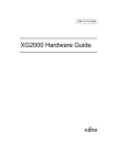
1.1.2
Chapter 1 Getting Started
Port Side
SFP Slots
Console Port
LED
•
10/100/1000BASE-T Ports
Console Port
Expansion Slot
LED
In order to set and operate the switch, use the console cable and D-SUB9pin cross cable
included in this package to connect to the PC.
Caution
The RJ45 Console Port jack is an RS-232 serial interface. Do not plug any other interface types
(Ethernet) into this jack. It may cause failure of the device.
Reference User’s Guide "1.1.5 Console Port Specifications" (pg.28)
•
10/100/1000BASE-T Ports
10/100/1000BASE-T Ports. These ports for connecting to Ethernet (10/100/1000BASET) Network Equipment.
Please use Category 5 LAN cable (if 1000BASE-T, use Category 5E or above) for
cabling.
Precautions
RJ45 ports 21 through 24 are combination ports that are associated with the four SFP ports. Their use is mutually
exclusive. If the RJ45 port 21 is cabled then the associated SFP slot cannot be used.
•
SFP Slots
Installing an SFP module in a SFP slot will allow connection to a 100BASE-FX/
1000BASE-SX/1000BASE-LX/1000BASE-ZX/1000BASE-BX-D/1000BASE-BX-U
optical cable. Its associated RJ45 port can no longer be used.
•
Expansion Slot
This slot is provided for the addition of an optional 10 GbE expansion card.
Reference "1.2.4 Expansion Card" (pg.25)
19
Items in the Package, Descriptions and Functions
XG0224 Hardware Guide
Chapter 1 Getting Started
LED Details
Link/Act/Speed
Fdx
Ready
Error
PSU
Check
Flash
Ext.PSU
21 SFP
21 Link/Act
22 SFP
22 Link/Act
23 SFP
23 Link/Act
24 SFP
24 Link Act
•
Ready LED
Indicates the operational state of the switch.
•
Error LED
Indicates a compact flash mount/access error occurred.
•
PSU LED
Indicates the switch power supply status.
•
Check LED
Lights orange when there is a problem. In such case, consult with the vendor's service
representative immediately.
•
Flash LED
Indicates the read/write status of the compact flash inserted into the switch.
Precautions
When the Flash LED is lit green, do NOT turn off power or reset the switch. The configuration being read or written may
be corrupted.
•
Ext.PSU LED
Indicates the status of the redundant power supply. Not supported.
•
SFP LED
Indicates the link up/down status of the SFP module.
•
SFP Link/Act LED
Indicates the link status and communication speed/status of the SFP module.
•
Link/Act/Speed LED
Indicates the link status and communication speed/status of the RJ45 port.
•
Fdx LED
Indicates whether the RJ45 port is operating in half or full duplex mode.
20
Items in the Package, Descriptions and Functions
XG0224 Hardware Guide
Chapter 1 Getting Started
LED Functions / Behaviors
LED Name
Ready
Error
PSU
Check
Flash
State
Status
Green
Switch has started up correctly
Green Blinking
Switch is running a Power On Self Test (POST) or running from the backup firmware
image (*)
Off
A problem has occurred
Orange
Indicates a compact flash mount/access error
Off
If a compact flash is installed, indicates no mount/access error
Green
PSU is operating correctly
Orange
A problem occurred with the PSU
Off
Power is off
Orange
A problem occurred that requires the switch be replaced
Off
The switch is operating normally
Green
Compact Flash Card is inserted correctly
Green Blinking
A compact flash read/write operation is occurring
Off
Compact Flash Card is not inserted
Ext.PSU
Off
Not supported
SFP
Green
SFP link is established
Off
SFP link is not established
Green
Established 1000M SFP link
Green Blinking
1000M SFP data traffic activity
Orange
Established 100M SFP link
SFP Link/Act
Link/Act/Speed
Fdx
Orange Blinking
100M SFP data traffic activity
Off
Link is not established
Green
Established 1000M link
Green Blinking
1000M data traffic activity
Orange
Established 100M or 10M link
Orange Blinking
100M or 10M data traffic activity
Off
Link is not established
Green
Duplex
Off
Half Duplex
*) During system POST, the Ready LED blinks green at a 0.5 second interval. When the switch is operating from the
backup firmware image, the Ready LED blinks at a 1 second interval.
21
Items in the Package, Descriptions and Functions
XG0224 Hardware Guide
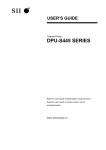
1.1.3
Chapter 1 Getting Started
Power Inlet Side
Product Manufacturing Label
Power Inlet
MAC Address Label
Firmware Label
Reset Switch
Redundant PSU
Connector
Compact Flash Card Slot Dump Switch
•
Power Inlet
AC power inlet for the power cable provided.
•
Product Manufacturing Label This indicates the model name, serial number, manufacturing date and Class 1 Laser
Product, etc..
•
Redundant PSU Connector
Connector for an external redundant power supply. Not supported.
•
Firmware Label
This indicates the firmware version.
•
MAC Address Label
This indicates the MAC address of the switch.
000000000000
•
Reset Switch
Press to reboot
•
Dump Switch
Press the dump switch to copy the following switch files to an installed compact flash
card.
Information
File Name
Configuration Definition 1
/cf0/config1
Configuration Definition 2
/cf0/config2
Firmware
/cf0/firmware
Error Log
/cf0/elog
The switch default configuration disables the dump switch. To activate the dump switch
use the dumpswitch command.
•
Compact Flash Card Slot
Insert a compact flash card to load/save configuration files or update firmware.
22
Items in the Package, Descriptions and Functions
XG0224 Hardware Guide
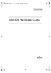
1.1.4
Chapter 1 Getting Started
Top Surface
Warning Label
•
Warning Label
This label describes the safety measures you should take when using this product.
23
Items in the Package, Descriptions and Functions
XG0224 Hardware Guide
Chapter 1 Getting Started
1.2
Options
1.2.1
SFP Modules
SFP modules (100BASE-FX/1000BASE-SX/1000BASE-LX/1000BASE-ZX/1000BASE-BX-D/1000BASE-BX-U) can
be used.
Precautions
•
Turn the switch power off to install a SFP module.
•
SFP modules can not be installed in the optional SFP+ extension card.
•
1000BASE-BX-D and 1000BASE-BX-U SFP modules must be used in pairs.
•
RJ45 ports 21 through 24 are 'combination' ports that are associated with the 4 SFP ports. Their use is mutually
exclusive. If the RJ45 port 21 is cabled then the associated SFP slot cannot be used.
Reference
1.2.2
"2.3.3 Connecting Twisted Pair Cable / SFP Module / SFP+ Module / CX4 Cable" (pg.37)
User’s Guide " SFP Module" (pg.24)
SFP+ Modules
SFP+ modules (10GBASE-SR/10GBASE-LR) are intended for use in the optional extension card.
Precautions
•
Turn the switch power off to install a SFP+ module.
•
SFP+ modules can not be installed in an SFP slot.
Reference
1.2.3
"2.3.3 Connecting Twisted Pair Cable / SFP Module / SFP+ Module / CX4 Cable" (pg.37)
User’s Guide " SFP+ Module" (pg.25)
Compact Flash
SANDISK SDCFJ-256-388 256 MB compact flash card is the only part approved for use in the switch compact flash slot.
Compact flash cards are installed into the compact flash slot on the power inlet side of the switch.
Reference
"2.3.4 Installing Compact Flash Card" (pg.40)
User’s Guide " Compact Flash Card" (pg.26)
24
Options
XG0224 Hardware Guide
1.2.4
Chapter 1 Getting Started
Expansion Card
The following describes the available expansion card options.
The optional expansion card is installed in the expansion slot on the port side of the switch. The following details the
functions/behaviors of each type of expansion card.
SFP+ Expansion Card
SFP+ Link/Act LEDs
SFP+ Slots
•
SFP+ Link/Act LEDs
Indicated the link status / communication status of the SFP+ Slots.
•
SFP+ Slots
Installing an SFP+ module in either SFP+ slot will allow connection to a 10GBASE-SR
or 10GBASE-LR optical cable.
LED Display Content
LED Name
SFP+ Link/Act
Reference
State
Status
Green
Link is established with SFP+
Green Blinking
10GBASE SFP+ data traffic activity
Off
Link is not established
"2.2.2 Installation of Extension Card" (pg.33)
User’s Guide " SFP+ Expansion Card" (pg.26)
25
Options
XG0224 Hardware Guide
Chapter 1 Getting Started
CX4 Expansion Card
CX4 Link/Act LEDs
CX4 Ports
•
CX4 Link/Act LEDs
Indicates CX4 port link status / communication status.
•
CX4 Ports
Connect to 10G Ethernet NW equipment using CX4 cable.
LED Display Content
LED Name
CX4 Link/Act
State
Status
Green
Link is established with CX4
Green Blinking
10G CX4 data traffic activity
Off
Link is not established
26
Options
Chapter 2
Installation
This chapter describes how to install the switch and connect it to Console PC.
2.1
2.2
2.3
Requirements for Installation Environment . . . . . . . . . . . . . . . . . . . . . . . . . . . . . . . . . . . . . . . . . . . . . 28
2.1.1
Installation Requirements . . . . . . . . . . . . . . . . . . . . . . . . . . . . . . . . . . . . . . . . . . . . . . . . . . . . . 28
2.1.2
Space Requirements . . . . . . . . . . . . . . . . . . . . . . . . . . . . . . . . . . . . . . . . . . . . . . . . . . . . . . . . . 30
Installation . . . . . . . . . . . . . . . . . . . . . . . . . . . . . . . . . . . . . . . . . . . . . . . . . . . . . . . . . . . . . . . . . . . . . . . . 31
2.2.1
Installation of the Switch. . . . . . . . . . . . . . . . . . . . . . . . . . . . . . . . . . . . . . . . . . . . . . . . . . . . . . 31
2.2.2
Installation of Extension Card . . . . . . . . . . . . . . . . . . . . . . . . . . . . . . . . . . . . . . . . . . . . . . . . . 33
Connecting the Equipment . . . . . . . . . . . . . . . . . . . . . . . . . . . . . . . . . . . . . . . . . . . . . . . . . . . . . . . . . . 35
2.3.1
Discharging Twisted Pair Cable . . . . . . . . . . . . . . . . . . . . . . . . . . . . . . . . . . . . . . . . . . . . . . . . 35
2.3.2
Cleaning SFP Module / SFP+ Module / Optical Connector . . . . . . . . . . . . . . . . . . . . . . . . . . 35
2.3.3
Connecting Twisted Pair Cable / SFP Module / SFP+ Module / CX4 Cable . . . . . . . . . . . . . 37
2.3.4
Installing Compact Flash Card . . . . . . . . . . . . . . . . . . . . . . . . . . . . . . . . . . . . . . . . . . . . . . . . . 40
2.4
Connecting to a Setup PC . . . . . . . . . . . . . . . . . . . . . . . . . . . . . . . . . . . . . . . . . . . . . . . . . . . . . . . . . . . 41
2.5
Time Setting. . . . . . . . . . . . . . . . . . . . . . . . . . . . . . . . . . . . . . . . . . . . . . . . . . . . . . . . . . . . . . . . . . . . . . . 44
2.6
Set up IP address . . . . . . . . . . . . . . . . . . . . . . . . . . . . . . . . . . . . . . . . . . . . . . . . . . . . . . . . . . . . . . . . . . 45
XG0224 Hardware Guide
2.1
Chapter 2 Installation
Requirements for Installation
Environment
Before installing the switch, please check the following:
•
Make sure that the switch and all the other options shown in this document are available for installation.
•
All the cables comply with the specifications of the interface connectors.
Warning
Do not connect cables to interface connectors other than those adaptable to the connector’s
specifications.
Reference "1.1.1 Parts List" (pg.18)
Install the product under the following environmental conditions
2.1.1
Installation Requirements
Caution
Install the product under the following conditions. Using the product outside the required
environment may cause failure of the product.
Temperature and Humidity Requirements
Temperature (degrees C)
Humidity (%RH)
Operation
0 to 40
15 to 85
Non-operation
0 to 50
8 to 90
Power Requirements
Item
Voltage
Frequency
Ground
Electricity
Inrush Current
Requirements
AC90V-264V
50Hz / 60Hz +2%, -4%
Separate ground wire from air conditioners and building, and D-class grounding with
ground resistance of 100 Ω or less.
80W
Maximum30A
Ensure installation environment that avoids lowering voltage to power supply
equipment at the time of power-on due to the inrush current, although there’s no
impact from the inrush current in normal use.
28
Requirements for Installation Environment
XG0224 Hardware Guide
Chapter 2 Installation
Installation Condition
Check List
Check the following items.
Check Item
Check Result
Nothing is put on the switch.
Vents are not obstructed.
The switch is not located on the table or not stuck on another switch.
The switch is not located under direct sunshine, near heating appliance, under high humidity
or in a dusty area.
The switch is not located on unstable places where vibrating, or tilting.
“About Warning Descriptions” has been thoroughly read.
29
Reference (pg.10)
Requirements for Installation Environment
XG0224 Hardware Guide
2.1.2
Chapter 2 Installation
Space Requirements
When installing the switch and providing maintenance, ensure the space below is maintained.
Ensuring the Space for Installation (Maintenance) of the Switch
When installing the switch and providing maintenance, ensure the space below is maintained.
Internal cooling fans of the switch allow the air intake from the left hand side and exhaust at the right hand side.
Ensure the indicated space below and do not put anything which avoids airflow.
200mm
XG0224
50mm
50mm
Airflow
Airflow
Port Side
200mm
50 or more
50 or more
50 or more
100 or more
Installation shelf
Unit: mm
30
Requirements for Installation Environment
XG0224 Hardware Guide
2.2
Chapter 2 Installation
Installation
This section describes how to install the switch.
2.2.1
Installation of the Switch
The following describes how to install.
Installation on 19” Rack
The switch can be installed and operated in the EIA standard 19” rack.
Prepare the following rack mounting components attached.
•
Rack Mounting Brackets (Qty 2)
•
M3 Countersunk Screws (Qty 8)
Reference "1.1.1 Parts List" (pg.18)
Precautions
•
Do not put rubber foots on when installing on the rack.
•
Please set the switch (product) to a place near the electrical outlet which the power cable will be connected and
secure a space for the power cable to be pulled off easily.
•
When installing the switch in the rack, separately procure screws according to the specifications of the rack.
•
Pay attention to control temperature inside and outside of the rack so that guaranteed operating temperature can be
maintained properly for the switch.
•
Reserve certain space for air cooling in accordance with the cooling structure of the switch.
•
Reserve certain space for air cooling in accordance with the cooling structure of the switch.
•
Check if power supply capacity (Rated Current) is sufficient from the power supply equipment such as power strip,
service outlet from other devices or rack.
•
When rack mounted devices with multiple power cables are connected to one single service outlet, or multiple rack
mounted devices with single power cable are connected to one single service outlet, there’s a risk that total ground
leakage current may exceed the power specifications.Pay special attention to the ground leakage current.
Installation procedure is described below.
1.
Place the switch on the flat place.
31
Installation
XG0224 Hardware Guide
2.
Chapter 2 Installation
Put rack mounting brackets on the switch using M3 Countersunk Screws (Qty 8).
Two ways below are possible for putting on rack mounting brackets.
[STANDARD]
[OFFSET]
M3 Countersunk Screws
Rack Mounting Brackets
M3 Countersunk Screws
Rack Mounting Brackets
Precautions
When putting on rack mounting brackets, make sure to use special screws included in the 19” rack brackets set. If other
screws are used, it may break. Also, make sure to use cross slot screwdriver corresponding to the screw thread.
3.
Fix the switch that rack mounting brackets are put at the procedure 2.
Installation screw
Precautions
Pre-occupied devices in the upper and/or lower row of the rack may interfere with the power cable of the switch from
being properly installed.In that case, plug the power cable to the switch before install it in the rack.
32
Installation
XG0224 Hardware Guide
2.2.2
Chapter 2 Installation
Installation of Extension Card
The extension cards can be installed to the switch as optional.
Below describes how to install each extension card.
Installation of SFP+ Extension Card / CX4 Extension Card
Below describes the case of SFP+ Extension card.
1.
Turn off the power of the switch.
Caution
Do not install/uninstall the extension cards with the power on. It may cause trouble.
2.
Loosen the screws on the extension slot and remove the cover panel.
3.
Install the extension card slowly sliding on the guide rail inside the extension slot.
Precautions
Rightly install the extension card on the guide rail. If not, the connection pin may break.
Fixed screw
SFP+ module
4.
Firmly fix the extension card in the switch with the screw.
5.
In case of the SFP+ card, plug in the SFP+ module.
33
Installation
XG0224 Hardware Guide
Chapter 2 Installation
Removing SFP+ Extension Card / CX4 Extension Card
1.
Turn off the power of the switch.
Caution
If the extension card is removed when the power is on, the Check LED will light up and the
switch will go into trouble state.
2.
Loosen the screws on the extension slot and remove the extension card.
3.
Put the cover panel on the extension slot, and fix it on the switch with the screws.
Precautions
When the switch is operated without the extension card, make sure to put the cover panel on the switch.
34
Installation
XG0224 Hardware Guide
2.3
Chapter 2 Installation
Connecting the Equipment
We recommend discharging static electricity of twisted pair cable before connecting it to the switch.
Also see below for how to install the compact flash card.
2.3.1
Discharging Twisted Pair Cable
Discharge static electricity of the twisted pair cable through the ground wire cable (ground wire for power supply,
buildings, etc.) using static electricity removal tool, before connecting twisted pair cable to the switch.
Precautions
2.3.2
•
Unplug both ends of the twisted pair cable from equipments (HUB, router, and workstation) during discharging
operation.
•
Do not use ground wire of electronic devices. Use grounded cable for power supply or buildings.
•
Do not short circuit with AC power supply when using ground wire for power suppl.
Cleaning SFP Module / SFP+ Module / Optical Connector
When invisible small dust is adhered to SFP module / SFP+ module / optical connector, optical signal will be shut or space
caused by dust will impede transmission of optical signal.
Therefore, clean up SFP module / SFP+ module / optical connector before connection.
Cleaning of SFP Module / SFP+ Module
1.
Blow dust away with cleanly dry air or nitrogen.
Check end face, and conduct operation below if dust is left.
2.
Lightly dampen a cleaning stick (1.25mm across, for LC/MU) with isopropyl alcohol. After wiping off
dust, slowly and carefully wipe off alcohol with a new and dry cleaning stick.
3.
Insert a cleaning stick to the optical connector insertion part of SFP module / SFP+ module, and
slowly wheel it.
SFP module
Cleaning stick
4.
Insert and slowly wheel a new cleaning stick, and dry the SFP module.
5.
Check if the dust is removed with 200-fold magnification fiber scope.
35
Connecting the Equipment
XG0224 Hardware Guide
Chapter 2 Installation
Cleaning of Optical Connector
1.
Remove the connector guard cap of optical fiber part, and check the connector end face.
If the end face is not clean, clean it with a reel type fiber cleaner.
2.
Push thumb holder of a fiber cleaner and open a cap of the fiber cleaner.
3.
When a cap slides and a new cleaning tape comes out, lightly apply the end face to a cleaning tape.
4.
Apply the end face of the connector and rotate it (quarter turn four times).
5.
Apply the end face to the cleaning tape, and move it to forward direction of a fiber cleaner.
Caution
Do not friction the end face to the cleaning tape. It will cause micro dust or scratch.
6.
Take thumb holder off, and close a cap of a fiber cleaner.
7.
Check the end face and continue cleaning if necessary.
Removal of Micro Dust
Remove micro dust on the optical fiber part following the method below if necessary.
1.
Wipe the optical fiber part with ethanol or cleaning fluid.
2.
Softly and slowly wipe the optical fiber part with cleaning fabric.
3.
Wipe with a new cleaning stick in the same fashion, and dry the optical connector.
Caution
• Do not use fluid such as bleach because it will damage optical coupling.
• Use ionizer when cleaning in order to avoid the ESD damage to SFP module / SFP+ module.
• SFP module cannot be washed with water. Do not use or clean SFP module / SFP+ module in a
wet space such as bathroom or kitchen.
• Carefully treat SFP module / SFP+ module as it sometimes becomes very hot.
Precautions
•
Do not use alcohol, spray, and cotton swab for cleaning of optical connector other than special optical connector
cleaner because dust on the end face of the optical connector plug may not be completely wiped off and more dust
may adhere.
•
Immediately connect optical connector to the switch after cleaning. Dust will adhere when the optical connector is
left unconnected.
•
Keep the connector guard cap fixed before using SFP module / SFP+ module in order to avoid contamination.
•
When SFP module / SFP+ module is contaminated, check end face and clean only if necessary.
•
If a lot of fluid is used, it will possibly be accumulated or leak out because SFP module / SFP+ module is not
hermetically closed.
36
Connecting the Equipment
XG0224 Hardware Guide
2.3.3
Chapter 2 Installation
Connecting Twisted Pair Cable / SFP Module / SFP+ Module
/ CX4 Cable
The following describes how to connect twisted pair cable, SFP module, SFP+ module, and CX4 cable.
Use straight cable when connecting with routers and terminals. Use crossing cable in case of cascading connection with
other switching HUBs with transmission mode at fixed setting other than auto negotiation.
Straight cable
crossing cable
optical cable
Port of the switch is set auto negotiation enable by default.
(However, SFP+ Slots and CX4 port only support 10Gbps full duplex mode fixed setting.)
Ports automatically apply to the maximum speed that plugged equipment supports by the auto negotiation function.
•
10/100/1000BASE-T port
: Up to maximum 1000Mbps full duplex mode
•
SFP slot
: Up to maximum 1000Mbps full duplex mode
Connecting Twisted Pair Cable
Insert twisted pair cable to 10/100/1000BASE-T port until it clicks.
Twisted pair cable
Precautions
•
In case of 1000BASE-T, usable twisted pair cables are unshielded twisted pair cable (UTP) over category 5E and
shielded twisted pair cable (STP).
•
RJ45 ports 21 through 24 are combination ports that are associated with the four SFP ports. Their use is mutually
exclusive. If the RJ45 port 21 is cabled then the associated SFP slot cannot be used.
•
Discharge twisted pair cable before connecting as twisted pair cable may be charged static electricity. Refer "2.3.1
Discharging Twisted Pair Cable" (pg.35) for discharging method.
37
Connecting the Equipment
XG0224 Hardware Guide
Chapter 2 Installation
Connecting SFP Module
Firmly install SFP module to SFP slot and lock module to the switch.
SFP module 100BASE-FX/
1000BASE-SX/1000BASE-LX/
1000BASE-ZX/1000BASE-BX-D/
1000BASE-BX-U
Caution
Make sure to turn off the power when inserting and pulling out the SFP module.
Precautions
•
Port 21 to 24 of 10/100/1000 BASE-T port and the same number ports of SFP port cannot be used at the same time.
Connect only ports that will be used with twist pair cable or optical cable with SFP module.
•
Make sure use 1000BASE-BX-D SFP module and 1000BASE-BX-U SFP modules in pairs.
•
Safely keep a guard cap of SFP module.
•
Make sure to clean the end face of SFP module / optical cable before connecting optical connector because the end
face may possibly be contaminated. Please refer to "2.3.2 Cleaning SFP Module / SFP+ Module / Optical
Connector" (pg.35) for cleaning.
•
Do not directly touch the contact part of SFP module by hands. Use wristbands when touching SFP module.
•
Connecting part to the optical cable of SFP module is the laser opening.
There are two types of SFP modules, veil latch type and standard latch type.
Below describes how to connect these modules.
•
Veil Latch Type
Insert SFP module to the SFP slot with a lever locked, and lock the module and the switch.
Connect optical cable (connector shape: LC) after inserting SFP module to the SFP slot.
When removing SFP module, unlock the lever, module and the switch, and remove the module after unplug the optical
fiber.
Lever
•
Standard Latch Type
Insert SFP module to the SFP slot, and lock the module and the switch.
Connect optical cable (connector shape: LC) after inserting SFP module to the SFP slot.
When removing SFP module, remove the module after pressing a tab to unlock the module and the switch.
Tab
38
Connecting the Equipment
XG0224 Hardware Guide
Chapter 2 Installation
Connecting SFP+ Module
Firmly install SFP+ module to SFP+ slot and lock module to the switch.
SFP+ module
Caution
Make sure to turn off the power when inserting and pulling out the SFP+ module.
Precautions
•
Safely keep a guard cap of SFP+ module.
•
Make sure to clean the end face of SFP+ module / optical cable before connecting optical connector because the
end face may possibly be contaminated. Please refer to "2.3.2 Cleaning SFP Module / SFP+ Module / Optical
Connector" (pg.35) for cleaning.
•
Do not directly touch the contact part of SFP+ module by hands. Use wristbands when touching SFP+ module.
•
Connecting part to the optical cable of SFP+ module is the laser opening.
Insert SFP+ module to the SFP+ slot with a lever locked, and lock the module and the switch.
Connect optical cable (connector shape: DLC) after inserting SFP+ module to the SFP+ slot.
When removing SFP+ module, unlock the lever, module and the switch, and remove the module after unplug the optical
fiber.
Lever
Precautions
Cable length will be as below based on the specification of the optical fiber cable
Type
MMF
Core/Cladding Diameter
62.5/125µm
50/125µm
Minimum Transimission Band
Cable Length (m)
160MHz/km
26
200MHz/km
33
400MHz/km
66
500MHz/km
82
2000MHz/km
300
Use the appropriate cable according to the installation place.
39
Connecting the Equipment
XG0224 Hardware Guide
Chapter 2 Installation
Connecting CX4 Cable
Firmly install CX4 cable to CX4 expansion card port and lock the cable.
CX4 Cable
Precautions
2.3.4
•
Make sure to firmly insert the cable straight from behind.
•
When bending the cable, make sure that the diameter of the bent cable does not become somaller than 10cm.
•
When pulling out the cable, make sure to pull the pull tab of the cable connector. The cable may disconnect if you
pull the cable itself.
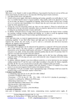
Installing Compact Flash Card
Compact Flash Card shall be installed in the power inlet side of the switch.
Caution
• Do NOT unplug during access. It may result in crashing setting data.
• Please refer to the following instructions, for installing the compact flash card. When installed
in a wrong direction, it may cause trouble to the switch.
Precautions
Make sure to use the specified product (SANDISK SDCFJ-256-388 256 MB).
1.
Firmly insert and lock the Compact Flash Card to Compact Flash Card Slot on the power inlet side of
the switch.
Precautions
Please be careful of the direction when inserting Compact Flash Card.
40
Connecting the Equipment
XG0224 Hardware Guide
2.4
Chapter 2 Installation
Connecting to a Setup PC
This is to connect a set up PC to the console port of the switch using RS232C cable.
Necessary Hardware / Software
Please prepare the hardware & software specified below to connect to the switch.
•
Personal Computer
1 unit of personal computer for setting up configuration is required.
•
RS232C cable(Cross, D-SUB9 pin)
RS232C cable is required to connect the set up PC to the switch.
Also, please use the console cable which is included in this product for connection.
Reference User’s Guide "1.1.5 Console Port Specifications" (pg.28)
•
Communication Software
Terminal software is required.
Connect RS232C Cable
1.
Confirm power of both the PC and the switch are off.
2.
Connect the RS232C cable and the console cable which is included in this product, and firmly fix
them with the screw.
3.
Plug in the RJ45 plug of the console cable to the console port of the switch.
41
Connecting to a Setup PC
XG0224 Hardware Guide
Chapter 2 Installation
Turn on the Power
Caution
• Please use the power cable included in this product. Also, please do NOT use this power cable
on other products.
• If the power outlet does not match with the power cable plug, please use the change plug
adapter.
As a safety measure to prevent electrical shocks, please make sure to connect the ground wire
of the change plug.
Precautions
Please set the switch (product) to a place near the electrical outlet which the power cable will be connected and secure
a space for the power cable to be pulled off easily.
1.
Connect the power cable to the electrical outlet.
2.
Plug in the power cable to the power connecter of switch power inlet side.
Power will turn on.
3.
The PSU lamp on the front panel of the device lights up in green.
PSU
42
Connecting to a Setup PC
XG0224 Hardware Guide
Chapter 2 Installation
Prepare a Setup PC
Log on using the terminal software.
1.
Start up the terminal software by using the set up PC.
2.
Set the setting conditions to the following;
Item
Setting
Start Bit
1
Data Bit
8
Parity Bit
n/a
Stop Bit
1
Synchronous System
Asynchronous Communication System (Start-Stop Communication System)
Communication Speed
9600
Flow Control
None
Number of digits on screen
80 (If other than 80 digits, set it through terminal command)
Number of rows on screen
24 (If other than 24 rows, set it through terminal command)
Please refer to the terminal software manual for instructions on setting conditions.
3.
Press [Return] key or [Enter] key.
Precautions
The following message may appear When pressing the [Return] key or [Enter] key. In such case, the switch is
processing another job, and waiting for such process to finish. Please wait for a moment until it finishes such process.
Waiting for completion of the other operation...
4.
Confirm “Login :” on screen.
5.
Key in “admin” and press [Return] key or [Enter] key.
6.
Confirm “Password:” on screen.
7.
Key in password, then press the [Return] key or [Enter] key.
Since password is not set at the initial state, simply press [Return] key or [Enter] key without keying in the password.
If the password is already set, key in the password. Then press [Return] key or [Enter] key.
8.
Confirm “#” is shown on screen
If the key in the wrong password, "invalid password." will be displayed, then the "Login :" will be displayed again. Please
repeat your process from item 5.
43
Connecting to a Setup PC
XG0224 Hardware Guide
2.5
Chapter 2 Installation
Time Setting
Make sure to set up the time before you do other settings of the switch. The time is not set at the initial timing of purchase.
Please refer below command for setting up time manually using console or telnet.
z Command
When setting time and date to be “Jan 1, 2009 12:30:00am” type in command
# date 2009/01/01.12:30:00
XG0224# configure
Switch to Configuration mode.
XG0224(config)# time zone -0500
When setting time zone to be “-0500“.
XG0224(config)# commit
Apply the configuration.
XG0224(config)# save
Save the configuration.
XG0224(config)# exit
Switch to Operation mode.
XG0224# date 2009/01/01.12:30:00
Set time and date to be “Jan 1, 2009 12:30:00am“.
44
Time Setting
XG0224 Hardware Guide
2.6
Chapter 2 Installation
Set up IP address
Please set the IP address at times when it is required.
Eg. When setting the switch through www browser or installing a firmware from the initial state of the purchase.
The following commands show how to set up the IP address (ex. 192.168.1.1).
z Command
XG0224# configure
XG0224(config)# lan 0 ip address 192.168.1.1/24 3
XG0224(config)# lan 0 vlan 1
XG0224(config)# commit
XG0224(config)# exit
XG0224#
Precautions
•
The IP address is not set at the initial state of the purchase. Please set the IP address through console.
•
When logging in by console, you will not be able to log in from the www browser. Please make sure to log off from
the console after setting up the IP address.
45
Set up IP address
XG0224 Hardware Guide
Index
Index
Number
M
10/100/1000BASE-T Port ........................................ 19
M3 Countersunk Screws .......................................... 18
MAC Address Label ................................................ 22
C
O
CD-ROM .................................................................. 18
Check LED ............................................................... 20
Communication Software ......................................... 41
Compact Flash .......................................................... 24
Compact Flash Card ................................................. 40
Compact Flash Card Slot
............................................................................ 22
Connecting ............................................................... 35
Console Cable .......................................................... 18
Console Port ............................................................. 19
CX4 Expansion Card ................................................ 26
Options ..................................................................... 24
P
D
Port Side ................................................................... 19
Power Cable ............................................................. 18
Power Inlet ............................................................... 22
Power Inlet Side ....................................................... 22
Power Requirements ................................................ 28
Prepare a Setup PC ................................................... 43
Product Manufacturing Label .................................. 22
PSU LED .................................................................. 20
Dump Switch ............................................................ 22
R
E
Rack Mounting Brackets .......................................... 18
Ready LED ............................................................... 20
Redundant PSU Connector ...................................... 22
Reset Switch ............................................................. 22
RS232C cable ........................................................... 41
Error LED ................................................................. 20
Expansion Card ........................................................ 25
Expansion Slot ......................................................... 19
Ext.PSU LED ........................................................... 20
S
F
Safety and Installation Guide ................................... 18
SFP LED .................................................................. 20
SFP Link/Act LED ................................................... 20
SFP Modules ............................................................ 24
SFP Slots .................................................................. 19
SFP+ Expansion Card .............................................. 25
SFP+ Modules .......................................................... 24
Software ................................................................... 41
Space for Installation ............................................... 30
Fdx LED ................................................................... 20
Firmware Label ........................................................ 22
Flash LED ................................................................ 20
H
Hardware .................................................................. 41
I
T
Installation ................................................................ 31
Installation Condition ............................................... 29
Installation on 19" Rack ........................................... 31
Installation Requirements ......................................... 28
Items in the Package ................................................. 18
Temperature and Humidity Requirements ............... 28
Terminal software .................................................... 43
Top Surface .............................................................. 23
Turn on the Power .................................................... 42
Twisted Pair Cable ................................................... 35
L
W
Link/Act/Speed LED ................................................ 20
Warning Label .......................................................... 23
46
XG0224 Hardware Guide
TA41001-6348
Issued on
November, 2009
Issued by
FUJITSU LIMITED
• The contents may be revised without prior notice.
• Fujitsu assumes no liability for damages to third party copyrights or other rights arising from the
use of any information in this manual.
• No part of this manual may be reproduced in any form without the prior written permission of
Fujitsu.
• EC declaration of conformity and the technical documentation are kept at the following
Fujitsu Europe Limited
Hayes Park Central, Hayes End Road, Hayes, Middlesex,
UB4 8FE, England, UK
+44-20-8573-4444