1
COSMAC ELF 2000
USER'S MANUAL
Sixth Edition
Copyright © 2004-2006 by Spare Time Gizmos.
Visit our web site at www.SpareTimeGizmos.com
Permission is granted to copy, distribute and/or modify this document under the terms of the GNU Free
Documentation License, Version 1.1 published by the Free Software Foundation; with no invariant sections; with the
front cover text “Portions Copyright © 2004-2006 by Spare Time Gizmos” and our URL, and with no back cover text. A
copy of this license may be obtained from http://www.gnu.org/licenses/fdl.txt.
CONTENTS
1
2
3
4
5
6
7
OVERVIEW ................................................................................................................................. 1
1.1
REGULATORY WARNING..................................................................................................... 2
1.2
SAFETY WARNING ............................................................................................................. 2
1.3
WARRANTY ....................................................................................................................... 2
ASSEMBLY.................................................................................................................................. 5
2.1
ERRATA ............................................................................................................................ 5
2.2
PART SELECTION ............................................................................................................... 5
2.3
OPTIONAL SUBSYSTEMS .................................................................................................... 7
2.4
SOCKETS AND SOLDERING ................................................................................................. 9
2.5
ASSEMBLY HINTS ............................................................................................................ 10
2.6
SWITCH PANEL ................................................................................................................ 10
2.7
HEX KEYPAD ................................................................................................................... 12
2.8
MOUNTING RAILS ............................................................................................................. 14
2.9
FINAL CHECKOUT ............................................................................................................ 14
HARDWARE DESCRIPTION ......................................................................................................... 16
3.1
CONNECTORS ................................................................................................................. 16
3.2
JUMPERS ........................................................................................................................ 17
3.3
BOOTSTRAP FLAG ....................................................................................................... 19
3.4
RECONFIGURING THE GAL............................................................................................... 19
3.5
SERIAL PORT .................................................................................................................. 20
SOFTWARE DESCRIPTION .......................................................................................................... 21
4.1
MONITOR FEATURES ........................................................................................................ 21
4.2
SETTING THE JUMPERS FOR THE MONITOR ....................................................................... 21
4.3
POWER ON SELF TEST (POST) ....................................................................................... 22
4.4
SERIAL CONSOLE AUTO BAUD.......................................................................................... 22
4.5
VIDEO CONSOLE EMULATION ........................................................................................... 23
4.6
MONITOR DATA ............................................................................................................... 23
4.7
STARTUP OPTIONS .......................................................................................................... 24
4.8
USING THE MONITOR BREAKPOINT FEATURE .................................................................... 24
4.9
CROSS ASSEMBLING AND DOWNLOADING PROGRAMS ....................................................... 25
MONITOR COMMAND REFERENCE.............................................................................................. 29
5.1
COMMAND REFERENCE.................................................................................................... 29
5.2
B[OOT] ............................................................................................................................ 29
5.3
BAS[IC], ASM, AND FOR[TH]........................................................................................... 29
5.4
CALL <ADDR> AND RUN <ADDR> ................................................................................... 30
5.5
CONT[INUE] ................................................................................................................... 30
5.6
E[XAMINE] <ADDR> AND E[XAMINE] <ADDR> <ADDR> ........................................................ 30
5.7
D[EPOSIT] <ADDR> <DATA> [<DATA> ...]........................................................................... 31
5.8
IN[PUT] <PORT> .............................................................................................................. 31
5.9
OUT[PUT] <PORT> <DATA> ............................................................................................. 31
5.10
SHOW COMMANDS ......................................................................................................... 31
5.11
SET COMMANDS ............................................................................................................. 34
5.12
TES [T] COMMANDS ........................................................................................................ 35
5.13
HEL[P]............................................................................................................................ 36
5.14
CLS................................................................................................................................ 36
5.15
LOADING INTEL HEX RECORDS ....................................................................................... 36
5.16
SEDIT ............................................................................................................................ 36
EDITOR AND ASSEMBLER .......................................................................................................... 39
6.1
EDITOR COMMANDS ......................................................................................................... 39
6.2
ASSEMBLER LINE FORMAT: .............................................................................................. 39
6.3
EXAMPLES ...................................................................................................................... 40
BASIC..................................................................................................................................... 41
7.1
INTRODUCTION ................................................................................................................ 41
7.2
ENTERING PROGRAMS ..................................................................................................... 41
7.3
EXPRESSIONS ................................................................................................................. 43
7.4
BUILT IN FUNCTIONS ........................................................................................................ 44
Page i
CONTENTS
7.5
PROGRAM STATEMENTS .................................................................................................. 46
7.6
ADVANCED TECHNIQUES .................................................................................................. 53
7.7
ERROR CODES ................................................................................................................ 55
8 FORTH ..................................................................................................................................... 57
8.1
STACK REPRESENTATION................................................................................................. 57
8.2
ARITHMETIC OPERATORS ................................................................................................. 57
8.3
CONTROL OPERATORS .................................................................................................... 57
8.4
VARIABLES ...................................................................................................................... 57
8.5
FUNCTION DEFINITION ...................................................................................................... 58
8.6
STACK OPERATORS ......................................................................................................... 58
8.7
OTHER FUNCTIONS .......................................................................................................... 58
8.8
EXTENDED FUNCTIONS .................................................................................................... 58
8.9
A BASIC FORTH TUTORIAL ............................................................................................... 59
8.10
DEFINITIONS OF EXTENDED FUNCTIONS ............................................................................ 63
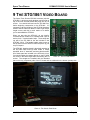
9 THE STG1861 VIDEO BOARD ................................................................................................... 65
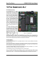
10 THE EMBEDDED ELF ................................................................................................................. 67
10.1
INTRODUCTION ................................................................................................................ 67
10.2
ASSEMBLY ...................................................................................................................... 67
10.3
INSTALLATION .................................................................................................................. 68
10.4
PROGRAMMER'S REFERENCE ........................................................................................... 68
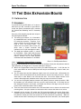
11 THE DISK EXPANSION BOARD.................................................................................................... 69
11.1
INTRODUCTION ................................................................................................................ 69
11.2
ASSEMBLY ...................................................................................................................... 69
11.3
INSTALLATION .................................................................................................................. 70
11.4
JUMPER SETTINGS........................................................................................................... 71
11.5
PROGRAMMER'S REFERENCE ........................................................................................... 72
11.6
PROGRAMMING TIPS AND OBSERVATIONS ......................................................................... 74
12 THE VT1802 VIDEO BOARD ...................................................................................................... 77
12.1
INTRODUCTION ................................................................................................................ 77
12.2
ASSEMBLY ...................................................................................................................... 77
12.3
INSTALLATION AND SETUP ................................................................................................ 78
12.4
VIDEO TIMING .................................................................................................................. 80
12.5
PROGRAMMER’S REFERENCE ........................................................................................... 80
12.6
ESCAPE SEQUENCES ....................................................................................................... 81
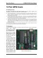
13 THE GPIO CARD ...................................................................................................................... 84
13.1
INTRODUCTION ................................................................................................................ 84
13.2
ASSEMBLY ...................................................................................................................... 84
13.3
INSTALLATION .................................................................................................................. 85
13.4
JUMPER SETTINGS........................................................................................................... 85
13.5
PROGRAMMER'S REFERENCE ........................................................................................... 85
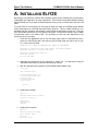
A. INSTALLING ELFOS................................................................................................................... 89
B. POST CODES .......................................................................................................................... 93
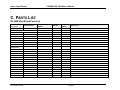
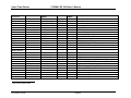
C. PARTS LIST .............................................................................................................................. 94
D. SWITCH PANEL ARTWORK ....................................................................................................... 107
E. RESOURCES AND REFERENCES ............................................................................................... 109
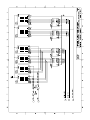
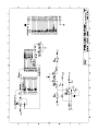
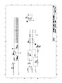
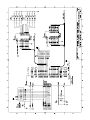
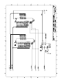
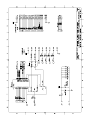
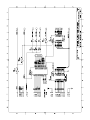
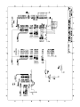
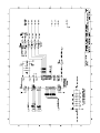
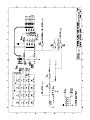
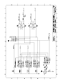
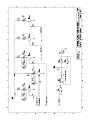
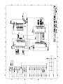
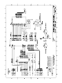
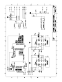
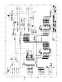
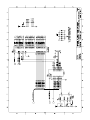
F. SCHEMATICS .......................................................................................................................... 110
Page ii
Spare Time Gizmos
COSMAC Elf 2000 User's Manual
1 OVERVIEW
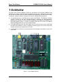
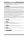
The Spare Time Gizmos’ COSMAC Elf 2000 is a reproduction of the original COSMAC Elf as
published in the pages of Popular Electronics magazine, August 1976. Although we tried to keep
the look and feel of the original, we had no hesitation about updating the Elf 2000 with the “latest”
in hardware. Unlike its ancestor, the Spare Time Gizmos’ COSMAC Elf 2000 features
An expanded memory to 32K RAM and an optional 32K EPROM. The EPROM, if installed,
contains a power on self test, extended hardware diagnostics, an Editor/Assembler,
interpreters for the BASIC, FORTH and CHIP-8 languages, and a BIOS and bootstrap for the
ElfOS disk operating system. A jumper is included to allow the CPU to start up at address
0x8000 (EPROM) rather than the normal 0x0000 (RAM).
An included CDP1861 Pixie chip video display circuit. If you don't have an 1861, the Elf 2000
has space and standoffs to mount a daughter board that plugs into the 1861 socket and
contains a discrete logic replacement for the 1861.
An I/O expansion connector and mounting holes for I/O daughter cards that fit on top of the
main board.
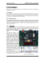
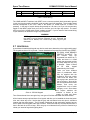
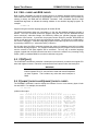
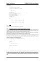
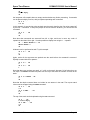
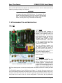
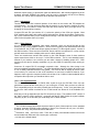
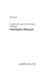
Photo 1 - The COSMAC Elf 2000
Photo 1 - The COSMAC Elf 2000
10/1/2006 4:23 PM
Page 1
Spare Time Gizmos
COSMAC Elf 2000 User's Manual
An optional lithium coin cell and a Dallas DS1210 NVR controller to make the RAM nonvolatile. Any programs you toggle in or download today will still be there tomorrow!
A true RS-232 compatible serial port using a DS275 EIA level shifter and a DE9F connector.
Fully decoded I/O ports, including the CDP1861, switches and display, so there will be no
conflicts with any add on peripherals. In addition, all I/O decoding, memory mapping and
other control functions are implemented in a 22V10 GAL so they can be easily changed
without any wiring modifications.
Six TIL311 displays for a full address and data display.
Switches mounted on a separate piece of plastic or aluminum, like the original ELF, that
connect to a header on the Elf 2000 PC board. If you don't like toggle switches, the Elf 2000
can also accommodate a Super Elf style hex keypad and push button controls.
An automatic bootstrap to allow the Elf 2000 to be used without any switches or keypad. On
power up, it can wait for download from a PC, or automatically begin running a program
stored in EPROM or non-volatile RAM. A VCC low voltage monitor in the Elf 2000 ensures that
the CPU is reset on power up and power down regardless of the switch settings.
A circuit that works with either the original CDP1802 chip or any of the later
CDP1804/1805/1806 chips. The classic Elf "load" mode, of course, requires a genuine 1802
chip.
1.1 REGULATORY WARNING
In the United States, the Federal Communications Commission requires that devices that use and
radiate radio frequency energy be certified in accordance with CFR Title 47, Parts 2 and 15.
Other countries will have different requirements.
The COSMAC Elf 2000 design is not in finished product form and has NOT been approved by the
FCC or any other regulatory agency worldwide. The user understands that approvals may be
required prior to the operation of the Elf 2000, and agrees to utilize the Elf 2000 in keeping with all
laws governing its operation in the country of use.
1.2 SAFETY WARNING
The COSMAC Elf 2000 board uses a Lithium coin cell battery. There is a danger of explosion if
this type of battery is incorrectly replaced. Replace with only the same or equivalent type
recommended by the manufacturer. Dispose of used batteries only in accordance with the
manufacturer's instructions.
1.3 WARRANTY
SPARE TIME GIZMOS OFFERS NO WARRANTY, EXPRESS OR IMPLIED, AS TO THE RELIABILITY OR
ACCURACY OF THE COSMAC ELF 2000 (“ELF 2000”) DESIGN. SPARE TIME GIZMOS OFFERS NO
WARRANTY, EXPRESS OR IMPLIED, AS TO THE ACCURACY OF THE INFORMATION PRESENTED IN THIS
DOCUMENT. SPARE TIME GIZMOS OFFERS NO WARRANTY, EXPRESS OR IMPLIED, AS TO THE SUITABILITY
OR CORRECTNESS OF ANY SOFTWARE OR FIRMWARE SUPPLIED IN CONJUNCTION WITH THE ELF 2000.
SPARE TIME GIZMOS MAKES NO REPRESENTATIONS AS TO THE SUITABILITY OF THE ELF 2000 FOR ANY
APPLICATION. IT IS SOLELY AND EXCLUSIVELY YOUR RESPONSIBILITY TO EVALUATE THE ACCURACY,
COMPLETENESS, AND USEFULNESS OF THE ELF 2000 AND ALL RELATED DESIGNS, SOFTWARE, AND
OTHER INFORMATION PROVIDED BY SPARE TIME GIZMOS. THE ENTIRE RISK AS TO THE USE AND
PERFORMANCE OF THE ELF 2000 IS ASSUMED SOLELY BY YOU.
NO REPRESENTATION OR OTHER AFFIRMATION OF FACT, INCLUDING, BUT NOT LIMITED TO, STATEMENTS
REGARDING CAPACITY, PERFORMANCE OF PRODUCTS, OR SUITABILITY FOR USE, WHETHER MADE BY
10/1/2006 4:23 PM
Page 2
Spare Time Gizmos
COSMAC Elf 2000 User's Manual
SPARE TIME GIZMOS EMPLOYEES OR OTHERWISE, WILL BE DEEMED TO BE
PURPOSE, OR GIVE RISE TO ANY LIABILITY ON THE PART OF SPARE TIME GIZMOS.
A WARRANTY FOR ANY
THE
WARRANTIES AND CORRESPONDING REMEDIES AS STATED IN THIS SECTION ARE EXCLUSIVE AND IN
LIEU OF ALL OTHERS, WRITTEN OR ORAL. SOME JURISDICTIONS DO NOT ALLOW THE EXCLUSION OF
IMPLIED WARRANTIES, SO THE ABOVE EXCLUSION MAY NOT APPLY TO YOU. THE LIMITED WARRANTIES
AND CONDITION REFERENCED ABOVE GIVE YOU SPECIFIC LEGAL RIGHTS. YOU MAY HAVE OTHERS, WHICH
VARY FROM JURISDICTION TO JURISDICTION.
IN
NO EVENT SHALL SPARE TIME GIZMOS OR ITS EMPLOYEES BE LIABLE FOR ANY COSTS OR DIRECT,
INDIRECT, PUNITIVE, INCIDENTAL, SPECIAL, CONSEQUENTIAL DAMAGES OR ANY OTHER DAMAGES
WHATSOEVER INCLUDING, WITHOUT LIMITATION, DAMAGES FOR COSTS OF PROCUREMENT OF SUBSTITUTE
GOODS OR SERVICES, LOST PROFITS, LOSS OF DATA, INTERRUPTION OF BUSINESS, OR LOSS OF USE,
ARISING OUT OF OR IN ANY WAY CONNECTED WITH THE USE OR PERFORMANCE OF THE ELF 2000 OR
YOUR RELIANCE ON THE ELF 2000 OR RESULTS FROM MISTAKES, OMISSIONS, INTERRUPTIONS, DELETION
OF FILES, ERRORS, DEFECTS, DELAYS IN OPERATION OR TRANSMISSION, OR ANY FAILURE OF
PERFORMANCE WHETHER BASED ON CONTRACT, TORT, STRICT LIABILITY OR OTHERWISE, EVEN IF SPARE
TIME GIZMOS HAS BEEN ADVISED OF THE POSSIBILITY OF DAMAGES.
BECAUSE SOME
STATES/JURISDICTIONS DO NOT ALLOW THE EXCLUSION OR LIMITATION OF LIABILITY FOR CONSEQUENTIAL
OR INCIDENTAL DAMAGES, THE ABOVE LIMITATION MAY NOT APPLY TO YOU.
IN
NO EVENT SHALL SPARE TIME GIZMOS' LIABILITY, IN THE AGGREGATE, EXCEED THE SUMS ACTUALLY
PAID BY YOU TO SPARE TIME GIZMOS AND ACCEPTED BY SPARE TIME GIZMOS FOR THE USE OF THE ELF
2000.
10/1/2006 4:23 PM
Page 3
Spare Time Gizmos
COSMAC Elf 2000 User's Manual
2 ASSEMBLY
Many thanks to the Elf 2000 builders who have contributed their experiences, suggestions and
frustrations to this chapter.
2.1 ERRATA
There are no known errors in Revision C and later of the COSMAC Elf 2000 board. To determine
the revision of your PC board, look for the text “ELF2K-1x” printed in copper along the edge of the
PC board. You’ll find it near the video/CDP1861 section. In this text, the “x” is the revision of
your PC board – for example, “ELF2K-1C” for revision C.
2.2 PART SELECTION
The complete parts list for the Elf 2000 is contained in Appendix A and, with the exception of the
CPD1802 CPU and the CDP1861 “Pixie”, all parts are common, modern, devices that should be
readily available. Most part values are non-critical and substitutions should not be a problem,
however when changing connectors or switches use care that the replacements will fit the
footprint on the PC board.
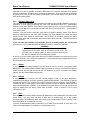
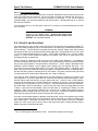
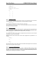
2.2.1 CPU Selection
The Elf 2000 is intended to use the CDP1802CE CPU; however this chip comes in many
variations that will also work. In particular, the ACE and the ACD and even the CD versions will
work just fine with no changes. If you are using an 1802 CPU of any type, then be aware that
jumper JP5 must be installed (see
section 3.2.3). JP5 is installed by
default.
The enhanced versions of the
CDP1802,
the
CDP1805
and
CDP1806 may also be used in the
Elf 2000 provided that jumper JP5
is removed (see section 3.2.3). The
1805/6
offer
many
additional
extended instructions which were not
available in the standard 1802,
however the 1805/6 implement IDLE
mode in a way which is incompatible
with the CDP1861 Pixie chip or the
STG1861 replacement. This may
cause problems for any graphics
software which uses the IDL (0x00)
instruction. Finally, the 1805/6 CPUs
do not implement the “Load Mode” of
the 1802, and this will render the
LOAD toggle switch useless. For
this reason, the CDP1805/6 CPUs
are recommended for use without the
toggle switch panel only.
The CDP1804 is a CDP1805 with an
internal program ROM. In principle,
a special startup sequence can be
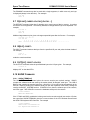
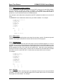
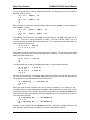
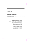
Photo 2 - Assembled Elf 2000
10/1/2006 4:23 PM
Page 5
Spare Time Gizmos
COSMAC Elf 2000 User's Manual
used with the 1804 to disable the internal ROM and force program execution from external
memory; however the Elf 2000 has no provisions for doing this. If you have an actual CDP1804
chip that you’re willing to part with, please contact Spare Time Gizmos and we’ll see what can be
done about making it work.
2.2.2 CDP1861 “Pixie” Chip
The CDP1861 is the standard video generation chip used by the original COSMAC Elf and by a
generation of video games powered by the 1802 CPU, including the RCA VIP. Unfortunately
CDP1861 chips have become quite scarce in recent years and you may have difficulty finding
one. If you do happen to have a real CDP1861 chip, then by all means use it – it’s intended to
work in this circuit.
However, if you don’t have a CDP1861, then there’s no need for despair. Spare Time Gizmos
makes a replacement for the 1861 which consists of a small daughter PC board that plugs
directly into the 1861 socket on the Elf 2000. The STG1861, as it’s called, contains two GALs
and two 74HC parts and is functionally equivalent to the original CDP1861. The software cannot
tell the difference.
If you use either the CDP1861 or the STG1861, be sure to install jumpers JP1, JP7 and JP8
(see section 3.2.1) to enable the DMA, INTERRUPT and EF1 outputs from the Pixie.
WARNING
If you don’t have a CDP1861 chip and you plan to use the STG1861
at some point in the future, then do not install a socket at U2. The
STG1861 uses a special header to make connections and can not
be used if a standard DIP socket has been installed.
Of course, if you don’t want video output from your Elf 2000 then there’s no reason why you need
either the CDP1861 or the STG1861 replacement. Just leave these parts unpopulated and your
Elf will work just fine without them.
2.2.3 SRAMs
If you intend to use a battery backup for your Elf 2000, be sure to use an LP (“low power”) suffix
SRAM chip. The standard 62256 SRAMs chips have stand by currents 100 times that of the low
power versions, and will drain the Lithium cell in a few hours. If you do not intend to use battery
backup, then any 62256 SRAM may be used.
2.2.4 EPROM
A 27C256 EPROM is used to hold the monitor program, power on self test, diagnostics,
programming languages, and disk operating system BIOS/bootstrap. The EPROM is optional
and may be omitted if you intend to only toggle in programs with the switches. If the EPROM is
installed, be sure to insert jumper JP4 to force execution to begin at address 0x8000 (the first
byte in the EPROM) after a RESET. If the EPROM is not used, remove JP4 so that execution will
begin at 0x0000 (the first byte in RAM) after a RESET. Refer to section 3.2.2 for more
information on JP4.
2.2.5 GALs
One GAL is used in the Elf 2000 to decode I/O addresses, memory addresses, and some of the
status LEDs. Not only does this save a great deal of random logic, but it also makes
reconfiguration of I/O addresses and/or the memory map a simple matter. Refer to section 3.4 for
more information on reconfiguring your GAL.
If you are concerned about power consumption, you’ll want to use an Atmel “Q” suffix part – this
device uses approximately ¼ the power of a conventional 22V10.
10/1/2006 4:23 PM
Page 6
Spare Time Gizmos
COSMAC Elf 2000 User's Manual
2.2.6 LED displays
Six TIL311 hexadecimal LED displays are used to display the current address and data. Either or
both (address and data) of these displays are optional and may be omitted without harm (refer to
section 2.3.6). Note that the TIL311 devices are bipolar logic, not CMOS, and use a tremendous
amount of power. Eliminating them from your Elf can easily reduce the power consumption by a
factor of 10!
2.2.7 Oscillator
The Elf 2000 uses one half sized “can” TTL crystal oscillator to generate the clock for both the
CPU and the Pixie chip. Notice that the oscillator frequency is divided in half before it is applied
to the CPU; that would mean that a standard CDP1802ACE could tolerate a maximum oscillator
frequency of 6 MHz (a 3 MHz CPU clock).
If you intend to use the CDP1861 video generator, or the STG1861 “clone” you must use a crystal
oscillator with the frequency 3.579545 MHz in order to generate the correct NTSC video timing.
In this case the CPU clock will be 1.7897725 MHz. You’ll find that crystals for this rather arcane
looking value are actually quite easy to obtain since it is the standard NTSC color burst
frequency.
2.2.8 DS1233
There is some confusion between the DS1233 part and the DS1233M. The “M” suffix indicates a
special version of the DS1233 which has the same pin out as some Motorola parts and because
of the different pin out, the DS1233M cannot be used directly in the Elf 2000. Electrically the
DS1233 and DS1233M are identical, so it should be possible to use the “M” version if you twist
the pins around to fit the PC board.
2.3 OPTIONAL SUBSYSTEMS
Many subsystems of the Elf 2000 are optional and may be omitted without affecting the function
of the remaining parts. In some cases when optional subsystems are omitted special jumpers or
connections may be required to enable the rest of the logic to continue functioning. This section
discusses the optional subsystems in the Elf 2000 and how to safely remove them.
You may also want to consider the option of building your first Elf with one or more of these
subsystems omitted to save both money and time. In this case you can always go back and add
the missing parts at any time.
2.3.1 Video (CDP1861 Pixie)
If you don’t want video from your Elf 2000, you can safely omit U2 (CDP1861), D2, R2, R3, R4,
J1 and jumpers JP1, JP7 and JP8.
To disable video temporarily but leave the hardware installed, simply remove jumpers JP1, JP7
and JP8 (see section 3.2.1).
2.3.2 EPROM
You may omit the EPROM, U3, so long as you also remove jumper JP4. In this case the CPU
will always start executing from address 0x0000 after a RESET, and you’ll need to ensure that
the SRAM contains valid data at that location. One way to do this would be to toggle in a
program using the switches.
2.3.3 Battery Backup
If you don’t require non-volatile RAM you can safely omit the DS1210 NVR controller, U5, and the
Lithium coin cell B1. However, if you do this you must connect two jumpers to enable the
10/1/2006 4:23 PM
Page 7
Spare Time Gizmos
COSMAC Elf 2000 User's Manual
SRAM. First, connect a jumper between U5 pin 8 and U5 pin 1 – this connects VBAT directly to
VCC so that the SRAM will receive power. Second, connect a jumper between U5 pin 5 and U5
pin 6 – this ties SAFE CS RAM L to CS RAM L to enable the SRAM.
2.3.4 Toggle Switches
The entire switch panel, including the eight data switches and the LOAD, RUN, MP and INPUT
switches, are completely optional. If they are omitted, the DS1233 will hold the CPU in the
RESET state for approximately 300ms after power up and then release the CPU to RUN mode.
The CPU will begin executing instructions at either location 0x0000 or 0x8000 as determined by
jumper JP4 (see section 3.2.2).
If you don’t want the switch panel, then in addition to omitting all the switches you may also omit
U14, and J5. Note that RP4, RP3 and U9 are still required; don’t be tempted to omit those!
If you use your Elf 2000 without any switch panel or keypad, then you need to solder two short
jumpers to the board in place of J5. The first connects pin 4 (“LOAD NC”) to pin 19 (“GND”) and
the second should connect pin 8 (“INPUT NC”) to pin 20 (“GND”). Since J5 is not needed if you
aren’t installing a switch panel or keypad, you can solder these two jumpers directly to the pads
reserved for J5. These two jumpers ensure that the INPUT and LOAD signals remain inactive at
all times. You may find that your Elf 2000 runs without them, but it’s not recommended.
You may also wish to jumper J5 pins 3, 5, 7, 9, 11, 13, 15 and 17 to ground as well (pin 12 will
do) – this will ensure that an INP 4 instruction always reads all zero bits, however this is not really
necessary. Of course, if you do this you’ll also need to keep U14 as well.
Another tip – if you want to use your Elf 2000 sometimes with a switch panel/keypad and
sometimes without, then go ahead and install the header for J5 anyway. When you are using the
Elf without a keypad you can use a wire wrap tool to jumper the necessary pins, and then later
remove the wire when you want to connect a switch panel.
2.3.5 Address Display
To delete the address display, omit DISP1 thru 4 and also U12. Note that U13 is still required.
2.3.6 Data Display
To delete the data display, omit DISP5, 6 and U13.
Before you decide that you don’t need the data display, remember that the power on self test in
the standard EPROM software uses the data display to show test results!
2.3.7 RS-232 Port
If you don’t want the onboard RS-232 port (if, for example, you have a UART on an I/O expansion
daughter board) then you can safely omit parts D16, J4, D6, JP6, JP9, and JP10.
2.3.8 Status LEDs
The status LEDs, LED1-5, may be omitted simply by removing the LEDs and the associated
resistors (R1, R5, R6, R7, and R8).
2.3.9 Expansion Bus Connector
If you don’t plan on adding any daughter cards, you can omit the expansion bus connector, J3.
10/1/2006 4:23 PM
Page 8
Spare Time Gizmos
COSMAC Elf 2000 User's Manual
2.3.10 Power Supply Regulator
If you always plan to use your Elf 2000 with an external, regulated 5V power supply, then you can
omit VR1 (along with any heat sink). Be sure to solder a jumper wire between the input (pin 1)
and output (pin 3) pins of VR1 to provide continuity for the power. If you use an external
regulated supply, you must also replace D5 with a wire jumper – otherwise the drop in VCC across
D5 would be excessive.
If you eliminate VR1 you can also get by without C1, however it is recommended that you keep
C2 in all cases.
WARNING
If you make this change, your Elf will have no protection against
reverse or over voltage inputs. Connect the wrong power
supply just once and you can easily fry all the chips in your
Elf 2000! You have been warned!
2.4 SOCKETS AND SOLDERING
The instructions for every kit that I have ever built, all the way from the legendary Heathkit1 on
down, have always said that “90% of the kits that don’t work after they’re assembled fail because
of the soldering.” The Elf 2000 PC board was laid out with “8 and 8” design rules, which means
that the traces are only 8 mils (that’s 0.008 inches!) wide and, in some places, there is only 8 mils
of “air gap” between adjacent traces or pads. The Elf 2000 is definitely not a “learn to solder”
project – if you’ve never soldered a board like this before, then it’d be a good idea to find
something cheaper to practice on!
When it comes to soldering, having the proper tools makes all the difference. A temperature
controlled soldering station with a 30 mil tip will can be purchased for about $100 and will make
the job much more pleasant. The right solder is important too – “63/37” solder is preferable to the
traditional “60/40” because it has a slightly lower melting point and requires less heat. You
should not be using anything larger than 31 mil (0.031 inch) diameter solder. And finally, you’ll
want a nice pair of wire cutters for trimming the leads on components after you’ve soldered them.
Get the kind that’s made for trimming wires on PC boards – they have a special cutting face that
cuts flush with the PC board without leaving any wire “stubs” sticking up.
You’ll want to wash the bare PC board before you start soldering to remove any grease or oils
from fingerprints. If you don’t wash them off, these oils will make the solder take longer to “flow”
and will require more heat and flux to get a good solder joint. I prefer to use a mildly abrasive
cleaner such as a Brillo pad, or Comet cleanser with a sponge, for cleaning. They do a better job
removing oils, but remember to rub ever so gently – heavy scrubbing will remove the silkscreen,
the solder mask, and even the plating! Just one, light, wipe with a wet and soapy Brillo pad is all
it takes! Lastly and most importantly, make sure the board is completely dry before you start
soldering. Even a tiny amount of water left in a hole will turn to steam when soldering heat is
applied and blow the solder right out of the hole! If you have it, “canned air” is ideal for removing
water from the holes and can be used to accelerate the drying process.
Use care to avoid solder bridges to adjacent traces and pads. Some of the bypass caps are also
very close to traces and, when you nip the leads on these, check that your cutters cut cleanly and
don’t cause shorts. And finally, be careful not to use too much solder on the pins; excessive
solder can “wick” up the pin to the top side of the board and cause invisible (because they’re
hidden under the IC socket) shorts there.
1
Yes, I’m old enough to have built one or two. I missed their golden years, though.
10/1/2006 4:23 PM
Page 9
Spare Time Gizmos
COSMAC Elf 2000 User's Manual
I strongly advise using good, high quality machined pin sockets for all ICs2. These sockets are
admittedly expensive; a 16 pin DIP socket might cost 50 cents and a 40 pin DIP more than dollar,
but they’re worth it if you ever need to replace an IC. Some people may object to the idea of
putting a 25 cent 74HC74 IC into a 50 cent socket, but it’s not the IC you are protecting – it’s the
PC board. If you ever fry that 74HC74 (and a single slip of the scope probe is all it takes!) then it
will require significant skill and equipment to unsolder that dead IC without damaging the board.
With a socket it takes only a few seconds to pop out the dead one a pop in a new one.
When soldering IC sockets and connectors, especially the larger ones, start by holding the part
tightly to the board and then soldering only two pins on diagonal corners. This will hold the part in
place temporarily while you turn the board over and make sure the part is flush against the PC
board. If it isn’t, then apply pressure to the part while using your iron to re-melt the solder on the
closest pin. The worst thing is to solder all 40 pins on an IC socket only to turn it over and find
that it’s skewed. It’s pretty difficult to desolder all those pins and repair the error at that point.
Lastly, clean the board again after you’re finished soldering by using a commercial flux remover
or, if you’ve used a solder with water soluble flux, by washing with a toothbrush and warm water.
Water soluble fluxes are corrosive in the long term and should never be left on the board.
Traditional rosin fluxes won't actually hurt anything if left behind, but the residue obscures the
traces and makes it harder to find shorts. Make sure everything is completely dry before you
begin installing parts in the sockets; once again, compressed or canned air can be used to
accelerate the drying process.
2.5 ASSEMBLY HINTS
9
Twenty-one 0.1µF 50VDC monolithic bypass capacitors are used in the Elf 2000. These are
identified by a box only on silk screen.
9
Notice that capacitors C1 and C2 are polarized devices and must be installed correctly. The
polarization is shown on the silk screen of all PC boards.
9
Header J5 should be mounted on the bottom (solder side) of the PC board with the pins
facing “down” (i.e. on the solder side). Because of the limited space available, a shrouded
header is not recommended for J5.
9
Remember to use a heat sink with VR1.
9
If you intend to use the STG1861 “Pixie” emulator, then do not install a dip socket at U2 (the
CDP1861 socket). The STG1861 daughter board uses special 0.1” female headers (which
are included in the STG1861 kit) and will not mate correctly with a standard DIP socket.
2.6 SWITCH PANEL
The switch panel is not part of the PC board and is constructed on a separate 5 ½” x 2" x 1/8”
thick piece of ABS plastic. Appendix D of this manual contains a full sized template for the switch
panel which you can print on a piece of adhesive decal stock and then use as a drilling guide.
Once you are done drilling, leave the decal in place as the remainder serves to label the various
switches.
Mount ten SPST toggle switches for D0 thru D7, RUN and MP. Note that all switches should be
mounted so that they are “ON” with the lever in the down (i.e. zero) position, except for the MP
switch. This includes the RUN switch; the MP switch alone should be installed so that it is ON
with the lever in the UP position.
2
Please don’t solder your 1802 chip or your 1861 chip to the board! And, of course, you
always want to socket the GAL and EPROM chips so that you can reprogram them if need be.
10/1/2006 4:23 PM
Page 10
Spare Time Gizmos
COSMAC Elf 2000 User's Manual
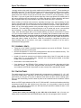
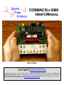
Mount a SPDT toggle
switch in the LOAD
position, and either an
SPDT push button or a
SPDT momentary toggle
switch in the INPUT
position. If you use a
momentary toggle switch
for INPUT, mount it so
that
the
momentary
position is UP.
The switches are wired
using a short piece of 20
conductor ribbon cable
terminated with a 20 pin
IDC female connector.
This connector plugs into
J5 on the main PC
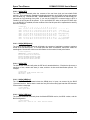
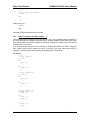
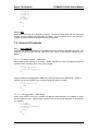
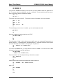
Photo 3 - Switch Panel (Rear View)
board, which you should
have installed on the
bottom of the PC board. It’s recommended that you use rainbow colored ribbon cable for the
switch panel connections, and install the connector so that the BROWN wire corresponds to pin 1
of J5, RED to pin 2 of J5, and so on.
Remember that pin 1 of J5 is the one with the square pad, and remember to count the pins of J5
while looking at it from the bottom of the PC board! If you hold the Elf 2000 PC board upside
down (i.e. solder side up) with the DE9 serial, RCA video and coaxial power connectors pointing
away from you, then the ribbon cable attached to J5 should have a BROWN conductor at the far
right side and a BLACK wire on the far left side.
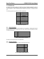
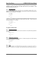
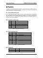
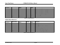
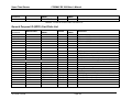
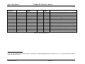
If you do it this way then wiring the switch panel is easy – Table 1 summarizes the wiring between
the switches and J5; you may also wish to refer to the Elf 2000 schematic, page 3, for more
detailed information. Notice that there are three ground connections in J5 – normally, pin 19 is
used as a ground for the eight data switches, pin 12 for the LOAD and INPUT switches, and pin
20 for the RUN and MP switches. There’s no magic to this, though, and you can assign the
grounds any way you wish.
The RUN switch is “upside down” because the associated function is really RESET (i.e. “NOT
RUN”!). When the RUN switch is down, the RUN/RESET input should be grounded (i.e. the
switch is ON) and when the RUN switch is UP (i.e. processor running) the RUN/RESET input
should be open (i.e. the switch is OFF). MP (memory protect) works the way you’d expect –
when the MP switch is UP the MP input is grounded (i.e. switch ON) and memory is protected.
PIN
1
3
5
7
9
11
13
15
Switch
N/C (VCC)
D7
D6
D5
D4
D3
D2
D1
10/1/2006 4:23 PM
Color
BROWN
ORANGE
GREEN
VIOLET
WHITE
BROWN
ORANGE
GREEN
PIN
2
4
6
8
10
12
14
16
Switch
N/C (VCC)
LOAD (NC)
LOAD (NO)
INPUT (NC)
INPUT (NO)
GND
N/C (unused)
RUN/RESET
Color
RED
YELLOW
BLUE
GREY
BLACK
RED
YELLOW
BLUE
Page 11
Spare Time Gizmos
PIN
17
19
Switch
D0
GND
COSMAC Elf 2000 User's Manual
Color
VIOLET
WHITE
PIN
18
20
Switch
MP
GND
Color
GREY
BLACK
Table 1- Switch Wiring
The LOAD and INPUT switches, both SPDT, have a common terminal (both connected to ground
in this circuit) and normally closed (NC) and normally open (NO) terminals. The normally closed
terminal corresponds to the “OFF” state of the switch (i.e. LOAD mode off, or INPUT not
pressed). In the case of a push button this generally isn’t an issue, but if you use a momentary
toggle for the INPUT switch then you’ll have to be sure get it the right way around. The same
thing is true for the LOAD switch, which is always a toggle. If you’re unsure of the internal wiring
of your switches, an ohmmeter will give a quick answer!
WARNING
SPDT toggle switches invariably have the common terminal in
the center, but push buttons frequently do not! Generally the
switch will be labeled, but if there’s any doubt, dig out your
ohmmeter!
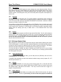
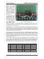
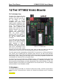
2.7 HEX KEYPAD
A push button hexadecimal keypad may also be used as an alternative to the toggle switch panel.
The keypad consists of 21 keys total – sixteen hexadecimal keys and five function keys, RESET,
GO (RUN), LOAD, MEMORY
PROTECT and INPUT. The
five
function
keys
are
illuminated from behind by T1
LEDs, and there is a small
beeper that generates a short
key beep whenever any key
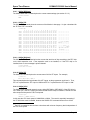
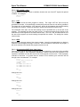
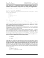
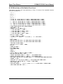
is pressed. Photo 4 shows
an
Elf
2000
keypad
assembled by Ken Rother.
There are three different
types of pushbuttons which
may be supplied with the
keypad kit. One has a white
insert inside the button; one
has a gray insert, and the last
has a red insert. Some of the
kits are supplied with all white
buttons, and some are
supplied with a mix of white
and gray or red. Since these
are surplus switches the
selection is limited to the
supply on hand and Spare
Time Gizmos doesn’t have enough of any one type to fill all the orders with the same buttons.
Photo 4 - Elf 2000 Keypad
All the buttons accept a printed insert for a legend, and after you've installed the insert the button
color won’t show any more. Notice that the gray and red buttons have their pins is a different
location than the white buttons. The PC board is designed so that each switch position has two
sets of pads to accommodate either type of button. Also notice that only the white buttons have a
hole in the back for a LED or lamp - don't use gray or red buttons for any of the five function keys
unless you intend to forgo back lighting them.
10/1/2006 4:23 PM
Page 12
Spare Time Gizmos
COSMAC Elf 2000 User's Manual
Two tips for installing the legends in the buttons. First, look closely at the buttons – there’s a
small slot on the side, just underneath the top of the cap. The slip of paper with the printing slides
in that slot. Do not try to disassemble the buttons! Also, it’s much easier to insert the legends
in the buttons before they’re soldered to the PC board. The space between the buttons is a little
tight once they’re in place, and they’re difficult to work on.
It's a good idea to do a "dry run" with the buttons and insert them all into the PC board before you
solder anything. Make sure that you have the right set of pads for each button type and that all
the buttons line up. Finally, make sure that the back light LEDs or lamps fit in the five function
keys. The five function keys accept either a T1 LED or a grain of wheat light bulb for back
lighting. If you use LEDs, you'll want to pick colors that complement that color of the button
legends. I've found that the LED back lighting is a little disappointing – it isn't quite bright enough
and the effect is a subtle in a normally lit room. It works great in the dark, however!
WARNING
Once the push button is soldered into place there's no way to
install or change the back light, so be sure you insert the LED or
lamp first! Be sure that the LED or lamp doesn't stick up so far
that it interferes with the operation of the push button.
Each back light has a separate transistor driver that can stand up to 100mA and voltages well
above VCC. This is especially useful if you use lamps instead of LEDs. If you do use lamps, you
may want to replace the LED current limiting resistors (R3, R5, R6, R9 and R12) with wire links
instead. Jumper JP1 connects VLED to VCC – if you elect to use lamps instead you may wish to
break this connection and supply VLED separately with a higher voltage and/or higher current
supply. Needless to say, VLED doesn't need to be regulated.
IMPORTANT
Look closely at JP1 and you'll see that there is a trace on the
solder side which connects the two pins by default. Normally
nothing, not even a header or shorting block, needs to be
installed at JP1. If you want to use a separate VLED supply
you'll need to cut this trace first.
Remember that it's going to be difficult to replace one of the back light lamps if it ever burns out,
so it'd be wise to operate these bulbs well below their rated voltage. Whether you use LEDs or
lamps, the LOAD and RUN ("GO") back lights are simply connected to the corresponding LEDs
on the main ELF 2000 PC board. There is no decoding for the RUN and LOAD states on the
keypad PC board and if you want to use these two LEDs/lamps you'll need to connect TP1
(LOAD) on the keypad PC board to U7 pin 16 on the main Elf 2000 PC board. Likewise, you'll
need to connect TP2 to U7 pin 15 on the Elf 2000 board.
It's not necessary to use the back lighting at all – you can simply omit the LEDs/lamps and all the
associated components if you choose. There are also alternate mounting locations for the
RESET, MEMORY PROTECT and INPUT LEDs in the upper left corner of the keypad PC board.
These will line up nicely with the LEDs already on the Elf 2000 PC board and you can install
these in place of the back lights if you prefer.
The function buttons RESET, GO, LOAD and MEMORY PROTECT all light up when the
associated condition is true. The INPUT button lights when any numeric key is pressed and then
goes out when INPUT is pressed. Notice that RESET button will also be lit while in LOAD mode.
This is normal.
Note that the MEMORY PROTECT button is not a toggle – pressing this button always sets the
MEMORY PROTECT flip flop. This condition is cleared by pressing any one of the RUN, LOAD
or RESET buttons.
10/1/2006 4:23 PM
Page 13
Spare Time Gizmos
COSMAC Elf 2000 User's Manual
The keypad contains a power on clear circuit that should cause it to always power up with RESET
on and LOAD, GO, MEMORY PROTECT and INPUT all off. The power on clear also causes a
short key beep whenever the power is switched on.
2.8 MOUNTING RAILS
The original COSMAC Elf was mounted on two strips of wood; the Elf 2000 uses two 6 ¾" x 1" x
3/8" thick strips of clear acrylic plastic instead. Drill small pilot holes in your plastic rails to line up
with the holes in the Elf 2000 PC board (there are four on each side) and the plastic switch panel
(two holes on each side). Mount the PC board and the switch panel to the plastic rails using
twelve 3/8” self tapping screws.
If you purchased a kit from Spare Time Gizmos, note that the mounting rails are part of the switch
panel kit and are not included in the basic Elf 2000 kit.
2.9 FINAL CHECKOUT
After you finish assembly, apply power before installing any ICs3. Place a DC milliammeter inline
with the power supply; with no ICs installed the current consumption should be essentially zero.
Use a DC voltmeter to verify that the voltage between pins 20 (negative) and 40 (positive) on the
microprocessor (CDP1802) socket; you should read 4.9 to 5.1V.
Next remove power and install all ICs except the CDP1802, CDP1861 (if you have it) and the
TIL311 displays. Install the TTL oscillator and the 22V10 GAL at this time. Turn on the power
and check the power consumption – it should be 100mA or less4. The Q, SC0 and SC1 LEDs
may or may not light, or they may glow faintly. Don’t worry about this. If you have access to an
oscilloscope, check that pin 1 of the CDP1802 has a 1.7897725MHz square wave.
Turn the power off and install the CDP1802 and (if you have it) CDP18615 chips. Turn on the
power and check the milliammeter – the power consumption should still be under 100mA, and
probably more like 50-75mA. Ensure that the RUN and LOAD switches are both set to OFF and
only the SC0 LED should be illuminated. Flip the LOAD switch ON and the green LOAD LED
should light; flip LOAD back to OFF and flip RUN to ON and, after a slight pause, the RUN LED
should light.
Finally, remove power one more time and install the six TIL311 displays. Notice that the TIL311s
have two notches on one end and one notch on the other end; the end with two notches is the
“top” (towards the CDP1802 socket) side. Flip the power on and check the milliammeter; the
TIL311s are TTL chips and are huge power hogs – the current drain will now be something
around 600mA! Use your voltmeter to double check the VCC one more time and verify that it’s
still between 4.9 and 5.1VDC.
If you don’t get these results, and especially if the current drain is significantly more than
predicted, then stop and figure out what’s wrong before proceeding.
If all’s well and your Elf 2000 has a switch panel then proceed to section 2.9.1, Switch Panel
Checkout. If your Elf has no switch panel but you are using the Spare Time Gizmos monitor
EPROM, proceed with section 2.9.2, EPROM Checkout.
3
You did socket all the ICs, didn’t you?
4
Assuming you are using the Atmel “Q” quarter power GAL specified in the parts list.
5
If you’re using the STG1861 replacement, do not install it at this time.
10/1/2006 4:23 PM
Page 14
Spare Time Gizmos
COSMAC Elf 2000 User's Manual
2.9.1 Switch Panel Checkout
Set all switches to the OFF position, including D0-D7 and flip LOAD to the ON position. The
LOAD LED should light and the address display should show 0000 (the data display will be
random). Flip/press INPUT and the display should read 0000 00. Now set the D0-D7 switches to
ON and flip/press INPUT again; the display should now read 0001 FF.
Next, set the data switches to 0xA5 (D7 ON, D6 OFF, D5 ON, D4 OFF, D3 OFF, D2 ON, D1
OFF, and D0 ON), flip/press INPUT and the display should show 0002 A5. Finally, set the data
switches to 0x5A, flip/press input, and verify that the display shows 0003 5A.
Set LOAD to OFF; set MP to ON, and then flip LOAD back to ON. The display will show 0000
5A. Flip/press INPUT and the display will show the contents of location 0 – 0000 00. Flip/press
INPUT three more times and you’ll see the next three bytes that you just entered; 0001 FF, 0002
A5, and 0003 5A.
If you are also using the Spare Time Gizmos monitor EPROM, then proceed with the next
section.
2.9.2 EPROM Checkout
Turn the power off and ensure that all jumpers are set as described in section 4.2 for monitor
EPROM compatibility. Connect an RS-232 terminal6 to J4 and set the terminal for 2400 baud, 8N-1 (8 data bits, no parity and 1 stop bit). Set all switches to OFF except RUN, which should be
set to ON. Turn on the power.
The RUN LED should light (if it doesn’t make sure you’ve set the RUN switch to ON!) and the
data display should show 997, followed by 98, and then gradually count down to 16. This means
that the monitor is ready for auto baud; press the ENTER (carriage return) key on the terminal.
The data LEDs will read 00 and on the terminal you should see something like this:
COSMAC ELF 2000 EPROM V15 CHECKSUM BA24 SRAM 32K INITIALIZED
Copyright (C) 2004 by Spare Time Gizmos. All rights reserved.
ElfOS BIOS Copyright (C) 2004 by Mike Riley.
For help type HELP.
>>>
If the LEDs stop counting at some number before 16, then refer to section 4.3, Power On Self
Test (POST), for help in diagnosing the problem.
6
A PC running terminal emulation software (e.g. KERMIT or HyperTerm) works fine.
7
Many of the numbers in this sequence, including the 99, go by so fast that you can’t see them.
10/1/2006 4:23 PM
Page 15
Spare Time Gizmos
COSMAC Elf 2000 User's Manual
3 HARDWARE DESCRIPTION
3.1 CONNECTORS
3.1.1 Power
J2 is the main power connector. It is a standard 2.1mm ID, 5.5mm long coaxial power connector
and the center conductor is positive. Diode D5 protects against accidental reverse polarity.
Using a standard 7805 regulator for VR1, the applied power may be anywhere from 9 to 12VDC.
Use care when applying voltages higher than 12V not to exceed the power dissipation limits of
VR1.
A fully populated Elf 2000, including all six TIL311 displays and the STG1861 video chip
substitute, uses approximately 600mA. Removing the six LED displays and the STG1861 will
reduce the current requirements to only about 100mA.
3.1.2 Console
J4 is a standard DB9 female connector. The wiring of this DE9F is such that it can connect
directly to a standard PC serial port (which uses a DB9 9 pin male connector) using a “straight
thru” (i.e. not a null modem) cable. Note that only TXD, RXD, and ground are connected.
Pin
2
3
5
Signal
TXD
RXD
GND
Table 2 – RS-232 Connector
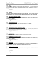
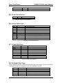
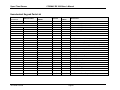
3.1.3 I/O Expansion
J3 is a general purpose expansion connector which can be used to connect to one or more
daughter boards mounted on top of the Elf 2000. Four mounting holes for #4-40 swage standoffs
to support the daughter board are also provided on the Elf 2000. Note that these daughter
boards are intended for I/O expansion only – J3 does not contain any memory address or control
signals. There’s hardly any need, since the Elf 2000 already contains 64K of memory! Table 3
shows the pin out of the I/O expansion header.
Pin
1
3
5
7
9
11
13
15
17
19
8
Signal
VCC
D0
D1
D2
D3
D7
D6
D5
D4
Q
Type
PWR
TRI8
TRI
TRI
TRI
TRI
TRI
TRI
TRI
O9
Pin
2
4
6
8
10
12
14
16
18
20
Signal
VCC
N2
N1
N0
MRD L
EF4 L
TPA
TPB
RUN
INTREQ L
Type
PWR
O
O
O
O
OD
O
O
O
OD
Tri-State.
10/1/2006 4:23 PM
Page 16
Spare Time Gizmos
Pin
21
23
COSMAC Elf 2000 User's Manual
Signal
EF2 L
GND
Type
OD10
PWR
Pin
22
24
Signal
EF3 L
GND
Type
OD
PWR
Table 3 – I/O Expansion Header (J3)
3.2 JUMPERS
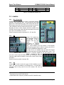
3.2.1 JP1, JP7 and JP8
Jumpers JP1, JP7 and JP8 are used in conjunction with the
CDP1861 video generator chip. JP7 connects the 1861 DMA
REQ to the CPU’s DMA OUT input; JP8 connects the 1861 INT
REQ output to the CPU’s INT REQ input, and JP1 connects the
1861’s DISPLAY STATUS output to the CPU’s EF1 input.
Normally all three of these jumpers would be installed if the
CDP1861 chip is being used, and all three would be removed if
the 1861 is not installed or not used.
Photo 5 shows the position of jumpers JP1, JP7 and JP8.
3.2.2
JP4
Jumper JP4 enables the
“auto bootstrap” feature of
the Elf 2000. If JP4 is
installed, then the CPU
begins
executing
Photo 5 - JP1, JP7 and JP8
instructions at address
0x8000 after a hardware
reset. Since 0x8000 is the first location in the EPROM,
installing this jumper has the effect of causing the CPU to
execute the EPROM bootstrap after a reset.
If jumper JP4 is not installed, then the 1802 CPU begins
executing instructions at location 0x0000 after a reset. This
address is normally mapped to the first location in the
Photo 6 - JP4
SRAM. Needless to say, it’s
your job to ensure that the RAM contents are meaningful, either by
using the toggle switch bootstrap or some other means, before using
this option.
Photo 6 shows the position of jumper JP4.
3.2.3 JP5
Jumper JP5 is used to select the type of CPU installed in the Elf
2000. JP5 must be installed for a CDP1802 CPU. If a CDP1805 or
CDP1806 chip is being used for the CPU instead, JP5 must be
removed.
9
Photo 7 - JP5
Output (driven by the ELF 2000 board).
10
Open-Drain with a 10K pull up resistor on the ELF 2000 PC board.
10/1/2006 4:23 PM
Page 17
Spare Time Gizmos
COSMAC Elf 2000 User's Manual
IMPORTANT!
As shipped from the factory, revision C and later of the ELF2K PC board
have a small trace shorting JP5 on the top side of the PC board. If you
plan to install a jumper at JP5, you must very carefully cut this trace with
a small knife first!
This means that by default, your Elf 2000 PC board is wired for an 1802 chip and, if you are using
an 1802, you don’t need to do anything. You don’t need to install a jumper at JP5 at all! If you
want to use an 1805/6 CPU, then you must first cut the trace between the two pins of JP5. If you
want to be able to select between the two CPU types, first cut the trace connecting the two pins of
JP5 and then install a jumper there.
Photo 7 shows jumper JP5.
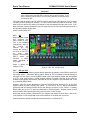
3.2.4 JP2
When installed, jumper
JP2
connects
the
INPUT switch to EF4.
This is the standard
arrangement used by
the
original
Elf;
however
you
may
remove this jumper if
you wish to use EF4
for
some
other
purpose. Note that the
INPUT
switch
still
functions in LOAD
mode regardless of
this jumper.
Photo 8 shows the
location of JP2.
Photo 8 - JP2, JP6, JP9 and JP10
3.2.5 JP9 and JP10
JP9 and JP10 are two position jumpers which determine the polarity of the RS-232 serial input
and output signals. Remember that a “proper” RS232 to TTL level shifter inverts the polarity of
the signal (i.e. the “active” or marking RS232 state is the more negative voltage and corresponds
to a TTL “high” level) and the “normal” polarity position of jumpers JP9 and JP10 is used by
software that originally expected the CDP1802 Q and EFx signals to be interfaced with a real
(e.g. MAX232) RS232 driver.
However, many Elf circuits attempted to interface RS-232 devices directly to the Q and EFx
signals without a proper RS-232 level shifter. In this case a 0V TTL signal corresponded
(assuming that the external RS232 device was willing to accept it) to the “active” or marking
RS232 state and a +5V TTL signal corresponded to a RS-232 space. Software written for this
kind of interface will expect JP9 and JP10 to be set to the “invert” position.
Notice that the two jumpers, JP9 and JP10 are “flipped” with respect to each other – that is, the
invert position on one corresponds to the normal position on the other and vice versa.
Photo 8 shows the location and the normal/invert positions of JP9 and JP10.
10/1/2006 4:23 PM
Page 18
Spare Time Gizmos
COSMAC Elf 2000 User's Manual
3.2.6 JP6
JP6 connects the RS-232 serial input to either EF3 or EF4. To disable the serial port input
completely (i.e. to leave both EF3 and EF4 free for other purposes), simply remove JP6
completely.
Photo 8 shows the location of JP2.
3.2.7 Other Jumpers
Note that jumper JP3 does not exist. It was used in an earlier revision of the PC board only.
3.3 BOOTSTRAP FLAG
Under normal conditions, the CLEAR (RESET) state sets the 1802 internal registers
X=P=IE=R(0)=0 and then the processor begins executing instructions at location 0 with R(0) as
the PC. If we want to start executing code directly from the EPROM after a RESET, it’s
necessary to “trick” the processor somehow into starting at location 0x8000 rather than 0x0000.
The 22V10 GAL, U7, is responsible for decoding the chip selects for both RAM and EPROM.
Ordinarily is uses A15 to do this; A15 = 0 selects the RAM and A15 = 1 selects the EPROM. The
hardware also contains a special “bootstrap” flag implemented by U9 section C; this flag is always
set (i.e. BOOTSTRAP = 1) by a RESET condition. This BOOTSTRAP flag is also an input to U7,
and when BOOTSTRAP is 1 the GAL modifies its chip select decoding so that the EPROM is
always selected regardless of the state of A15.
Once again, as long as the BOOTSTRAP flag is set, the EPROM will be selected for all memory
references. Address bit A15 becomes a “don’t care.” The RAM can never be selected under
these circumstances. This combination causes the processor to execute instructions from the
EPROM after a reset, even though the PC = 0x0000. As soon as possible after RESET, the
EPROM code should execute a long branch to the correct 0x8xxx address and then clear the
bootstrap flag.
Clearing the BOOTSTRAP flag is also up to the GAL via the CLR_BOOTSTRAP output. The
current GAL programming will assert this output any time N != 0, thus the first I/O instruction of
any kind after a RESET clears the bootstrap flag. This works well with the current EPROM code
since one of the first actions after a reset is to load POST code 99 into the displays, and the I/O
output instruction that loads the data display will also clear BOOTSTRAP as a side effect.
The entire BOOTSTRAP mechanism may be defeated by removing jumper JP4 (see section
3.2.2) which prevents the BOOTSTRAP flag from getting to the GAL in the first place. If JP4 is
removed, then RAM is always addressed from 0x0000 to 0x7FFF and the processor will be
executing instructions from RAM immediately after a RESET. This is most useful when you
intend to hand toggle in programs using the switches; however it can also be useful if the backup
battery is installed and the RAM contents are known to be valid.
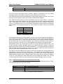
3.4 RECONFIGURING THE GAL
The 22V10 GAL is responsible for most of the random logic, address and I/O decoding in the Elf
2000. In particular, the GAL is responsible for:
¾
¾
¾
¾
¾
Decoding the EPROM and SRAM chip selects
Decoding the I/O select for the switch register and data display
Decoding the I/O select for VIDEO ON and VIDEO OFF
Handling and clearing the BOOTSTRAP flag (see section 3.3)
Deciding when the RUN and LOAD LEDs are illuminated
Besides the simple fact that it saves a handful of discrete logic chips, the other really wonderful
thing about this is that it is possible to change the way the ELF 2000 operates simply by
reprogramming the GAL.
10/1/2006 4:23 PM
Page 19
Spare Time Gizmos
COSMAC Elf 2000 User's Manual
For example, suppose you wanted to change the I/O address for the switch register from its
current default (4) to 3. No problem – just reprogram the GAL and it’s done. Absolutely no wiring
changes are required!
Or maybe your Elf 2000 doesn’t have any TIL311 displays, and you’d like to add some extra I/O
instructions so that the firmware can blink the RUN and/or LOAD LEDs? Easy – just add the new
I/Os to the GAL and you’re done. No need to even warm up the soldering iron.
Or, for another example, currently the BOOTSTRAP flag is cleared by the first I/O, any I/O, after a
RESET. Suppose you wanted to change the system so that the BOOTSTRAP flag could be
cleared only by an I/O to a specific port? Or maybe you’d rather not have it cleared by any I/O
but instead by the first real memory reference to an address ≥ $8000? You guessed it – just
reprogram the GAL!
Or, for one more example, currently SRAM is mapped from $0000 to $7FFF and EPROM from
$8000 to $FFFF. Suppose you wanted to change that around? Yep, no problem – just
reprogram the GAL!
If you have a particular piece of software that you want to run on your Elf 2000, then the GAL
gives you tremendous flexibility in changing the hardware configuration to accommodate the
software, all without changing a single wire…
3.5 SERIAL PORT
The DS275 chip used in the Elf 2000 provides true EIA (i.e. +/- 15V) signaling levels for the RS232 port, however it has one significant limitation. The DS275 is capable of half duplex operation
only. That is, the serial port can receive characters and it can transmit characters, but it cannot
do both at the same time. Since the serial port in the Elf 2000 is intended to be used with a
“software” UART algorithm in the 1802 CPU, this is not a serious limitation.
Except, that is, on one situation. There are some UART algorithms that implement the echo of
characters read at the bit level. That is, the character read routine attempts to echo each bit back
to the Q bit output as each bit is being read. That’s full duplex and will not work (you’ll get
unexplained garbage characters) with the DS275. The solution is to change to a character level
echo instead – read an entire 8 bit character and assemble all the bits into a byte, and then echo
the entire 8 bit character after input is finished. This algorithm works fine with the DS275 and the
different is imperceptible to the user.
10/1/2006 4:23 PM
Page 20
Spare Time Gizmos
COSMAC Elf 2000 User's Manual
4 SOFTWARE DESCRIPTION
You can program a 27C256 EPROM with any 1802 code you like and install it at U3, or you can
use the standard EPROM software provided by Spare Time Gizmos. The standard EPROM
contains several distinct software modules, including
•
A monitor written by Spare Time Gizmos which provides hardware diagnostics, program
debugging and downloading features.
•
A VT52 terminal emulator for use with the Spare Time Gizmos VT1802 80 column video
card. The video card is described in chapter 12.
•
A disk BIOS written by Mike Riley and compatible with the ElfOS disk operating system.
The BIOS contains many useful functions that you are free to call from your own
assembly language programs. Please refer to Appendix E for references to BIOS and
ElfOS documentation. Appendix A describes the procedure for installing ElfOS on your
Spare Time Gizmos Elf 2000 platform.
•
A simple text editor and a load-and-go assembler, written by Mike Riley, which allows you
to type in, edit, assemble and then run 1802 assembly language programs. The
Editor/Assembler is documented in Chapter 6.
•
A full featured BASIC interpreter, written by Mike Riley.
Chapter 7.
•
A Forth interpreter, also written by Mike Riley and described in Chapter 8.
BASIC is documented in
The remainder of this chapter will describe the Spare Time Gizmos monitor for the Elf 2000.
4.1 MONITOR FEATURES
The Spare Time Gizmos monitor is a multipurpose piece of software which lives in the EPROM
and adds a number of useful features to the Elf 2000.
•
A power on self test (POST) that performs a basic test of all Elf 2000 components.
•
A more extensive diagnostic that performs in depth tests of certain Elf 2000 subsystems.
•
A down loader that can receive Intel .HEX format files over the console serial port and
load them directly into memory.
•
Basic memory examination and modification commands.
•
A program break point feature, including a register dump and the ability to continue
execution after the break.
•
A bootstrap for the ElfOS disk operating system.
•
A simple command line interpreter.
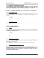
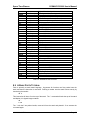
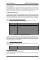
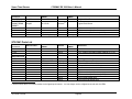
4.2 SETTING THE JUMPERS FOR THE MONITOR
The monitor requires that some of the COSMAC Elf 2000 be configured properly before it can
run. Table 4 summarizes the jumper settings required to run the EPROM monitor.
NOTE
The photos shown in section 3.2 all depict the jumpers
in the correct positions for the EPROM monitor!
10/1/2006 4:23 PM
Page 21
Spare Time Gizmos
COSMAC Elf 2000 User's Manual
Jumper
JP1
JP2
JP3
JP4
JP5
JP6
JP7
JP8
JP9
JP10
Expected setting for Monitor EPROM
Installed if you have a CDP1861/STG1861.
Otherwise removed.
Installed.
Unused (doesn’t exist!)
Installed (automatically start the monitor).
As required by your CPU chip.
RxD to EF3.
See JP1.
See JP1.
RxD invert.
TxD invert.
Table 4 - Jumper Settings for Monitor EPROM
4.3 POWER ON SELF TEST (POST)
Immediately after a RESET, provided that jumper JP4 is installed (see section 3.2.2), the CPU
begins executing instructions from the EPROM, and the first thing the EPROM code does is to
execute a simple test of the Elf 2000 components. This power on self test (aka POST) displays a
different two digit number on the data display for each test; if a particular test fails, the processor
will halt leaving the code for that test visible on the display. Thus it’s easy to identify the cause of
a failure from the two digit POST code shown.
Appendix B gives a list of the current POST codes and their meanings. These are current as of
EPROM monitor version 76. Note that many of these codes are not necessarily errors – they
simply show progress thru the sequence of tests. A POST code is only a problem if the system
halts while it is displayed.
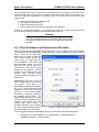
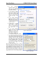
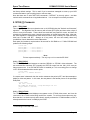
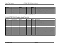
4.4 SERIAL CONSOLE AUTO BAUD
After the majority of the POST is completed, the monitor will attempt to determine the console
terminal port and baud rate by waiting for you to type either a carriage return (CR) or a line feed
(LF) character11. A carriage return will also enable monitor echo of all future input; a line feed
does not. In the latter case it’s presumed that your terminal has a local echo feature.
The data display (POST code) will show 16 while the monitor is waiting for you to type CR or LF.
Either the serial port on the main board or the UART serial port on the Disk Expansion card may
be used for the console terminal and, during the auto baud phase, the Elf 2000 will respond to
which ever port receives a CR character first. With a 3.579545 MHz clock, the Elf 2000 mother
board serial port is able to support any baud rate up to 2400bps. The UART serial port supports
any standard baud rate from 2400bps thru 19,200bps regardless of the CPU clock. The
character format used by both ports is 8-N-1 (8 data bits, no parity, and 1 stop bit) regardless of
the baud rate. After recognizing your terminal’s port and baud rate, the monitor will print a sign
on message that looks something like this:
COSMAC ELF 2000
EPROM V48 CHECKSUM BA24
SRAM 32K
INITIALIZED
The monitor will remember the console port baud rate in RAM, and if your Elf 2000 has the
Lithium battery backup option installed on subsequent startups the monitor will skip the auto baud
step and re-use the last baud rate memorized. If your Elf has the Disk Expansion card installed
with the Non-volatile RAM (NVR) option, then the monitor will remember the console port and
11
The line feed/no local echo option may be used with the mother board serial port only. The
UART serial port supports only the CR/local echo option.
10/1/2006 4:23 PM
Page 22
Spare Time Gizmos
COSMAC Elf 2000 User's Manual
baud rate in NVR even if the main memory does not have the battery backup option. If this
should become a problem, set the toggle switches to 0100 0011 (see section 4.7) before
rebooting to erase the memory (see section 4.7).
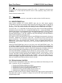
4.5 VIDEO CONSOLE EMULATION
If both the VT1802 80 column video card (Chapter 12) and the GPIO card (Chapter 13) are
installed and pass the power on self test, then the monitor will automatically use them to emulate
a VT52 style terminal as the Elf 2000 console. The VT1802 card provides the display output and
the PS/2 interface on the GPIO provides the keyboard input. Additionally, the speaker on the
GPIO card, if it is installed, will be used as the console terminal’s “bell”.
When both cards are installed and working, the monitor always uses the VT1802/GPIO
combination as the console terminal. No serial console auto baud is performed; post step 16 will
be skipped, and both serial ports are ignored by the monitor. The POST and initialization for the
UART chip is still executed if the Disk/UART/RTC card is present and you can of course still write
your own programs which use the UART.
NOTE
The “bit banged” motherboard serial port cannot be used when
the VT1802 is installed. This is because the DMA and interrupt
overhead associated with the VT1802 precludes accurate timing
for the software serial port emulation.
Console emulation works only if both the VT1802 and GPIO cards are installed. If only one is
present, then the POST will still execute the self test and initialization for that card, however the
monitor will attempt to use either the motherboard serial port or the UART as the console. If the
GPIO card is installed alone, you can still write programs which use the PS/2 keyboard port, but
the monitor will ignore it.
And if the VT1802 card is installed alone, the POST will initialize it and start the screen refresh
DMA and interrupts running, but the monitor will ignore it. You can, however, still write your own
programs which call the VT52 emulator firmware in the Elf 2000 EPROM directly and use that to
display text on the VT1802.
4.6 MONITOR DATA
The monitor reserves one page of RAM memory from $7F00 to $7FFF. Modifying bytes in this
page with the DEPOSIT command may cause unpredictable results including system hangs and
monitor crashes. Any machine language programs you write should avoid this page of memory
and, naturally, you should not attempt to download any data to it.
If you do manage to corrupt the monitor’s data page and you happen to have the battery backup
option, then even a reset or power cycle may not clear the problem! In this case you can try
setting the switch register to 0100 0011 (see section 4.7) and rebooting – this will force RAM to
be cleared. If that doesn’t work (or if you don’t have a switch register) then the only other option
is to turn the power off, remove the Lithium backup battery, wait a few minutes for the RAM to
discharge, and then turn the power back on again.
Any time the VT1802 video card is installed, whether or not the GPIO is also installed, the monitor
also reserves 2048 bytes of RAM memory from $7700 to $7EFF for use as a frame buffer and to
hold local variables for the VT52 emulator code. Any programs you write should also avoid using
this area of memory if you plan to use the VT1802.
The BIOS f_freemem function (see Appendix E) for the Elf 2000 knows about the monitor’s data
page at $7F00 and always adjusts the amount of free memory accordingly. Better yet, the BIOS
is also able to determine whether the VT1802 option is installed and, if it is, adjust the amount of
10/1/2006 4:23 PM
Page 23
Spare Time Gizmos
COSMAC Elf 2000 User's Manual
free memory downward to allow for the VT1802 frame buffer. Thus the safest and most portable
option is to always use the BIOS f_freemem function to determine the amount of available RAM.
4.7 STARTUP OPTIONS
During the power up sequence, the monitor can recognize several special patterns of the toggle
switches in the switch register and perform special startup actions. Currently three such special
patterns are recognized:
SWITCHES
1000 0001
0100 0010
0100 0011
Startup Action
special CHM startup mode
force SRAM to be initialized
force SRAM and NVR both to be initialized
Table 5 - Special Startup Options
To use one of these options, the switches must be set to this pattern before the CPU is reset or
power applied. For a normal startup sequence, the switches may be set to any other pattern; all
zeros are recommended.
4.8 USING THE MONITOR BREAKPOINT FEATURE
Whenever the monitor starts one of your machine language programs running, whether it is with
the CALL or the RUN command, it will initialize R1 with the address of a breakpoint routine that is
a part of the monitor. Provided that your program does not change the contents of R1, and
provided that your program keeps a valid stack pointer in R2, a break point can be placed in your
program with this two byte sequence:
MARK
SEP R1
; $79
; $D1
When a break point occurs, the monitor’s break point routine will save the CPU’s context,
including X, P, D, DF and registers 2 thru F, into the monitor’s data segment. This process
requires three bytes on your stack before control can be transferred to the monitor’s stack.
Registers R1 and R0 are not saved by the break point routine. Presumably this is not a problem
in the case of R1 (since you were using it for the break point program counter anyway!) but you
might regret the loss of R0. And in particular, this precludes the use of the break point feature
with any code that uses either interrupts or DMA or both.
WARNING!
Let’s say that again – the monitor’s break point feature does not
save (and hence the CONTINUE command cannot restore) the
contents of registers R0 or R1. All other CPU state is saved.
After saving the CPU state, the monitor’s break point routine will print out the entire CPU status:
BREAKPOINT @ XP=23 D=AA DF=1
R0=0000 R1=0000 R2=7F7D R3=0102
R4=FA7B R5=FA8D R6=82A0 R7=7FA8
R8=0000 R9=82DE RA=8CF7 RB=FEFF
RC=7FAF RD=0100 RE=1100 RF=7FB7
and then a command prompt. You can use the EXAMINE and or DEPOSIT commands to poke
around in what your program is doing, and you can also use the CONTINUE command to restore
the CPU’s state and continue execution of your machine language program. If you do elect to
continue, execution will resume at the next instruction after the SEP R1.
Note that the monitor prints the contents of all sixteen registers after a breakpoint, however (one
more time!) the values printed for R0 and R1 have no significance.
10/1/2006 4:23 PM
Page 24
Spare Time Gizmos
COSMAC Elf 2000 User's Manual
Since this break point feature requires some cooperation from your program (unlike other, more
powerful CPUs, which can implement a completely transparent break point) it’s worth while to go
over once again the requirements for making it work. To use the break point feature, your
program must
¾
¾
¾
¾
Not use or care about the contents of R0
Not change the contents of R1
Keep a valid stack pointer in R2
Ensure that there are at least three free bytes on the R2 stack
So long as it meets these conditions, your program can contain any number of break points and
you’ll be able to continue execution of your program after it hits one.
WARNING!
The break point feature requires the use of registers R0 and R1,
which is incompatible with the VT1802 video card. If the VT1802
is installed, the break point feature and all related commands are
disabled.
4.9 CROSS ASSEMBLING AND DOWNLOADING PROGRAMS
There are several cross assemblers for the 1802 which run on the IBM PC and other systems.
Two particularly useful examples are TASM and rcasm – refer to Appendix E for links to both of
these. Since the Elf 2000 ROM
monitor has the ability to load Intel
HEX format records directly (see
section 5.15), the output from any
cross assembler in this format can
be downloaded directly to the Elf
2000 over the console serial port.
And because each HEX file record
contains its own checksum, which is
verified by the Elf 2000 monitor, this
method even provides simple
protection against corrupted files or
downloads.
Downloading HEX files to the Elf
2000 is simple with the exception of
one caveat – since there is no
handshaking between the Elf and the
PC, the PC terminal program must
implement some form of transmit
pacing (i.e. a fixed delay between
characters) to prevent overrunning
the relatively slow Elf 2000. The
HyperTerminal program can do this;
a free (or at least no additional cost!)
version of this program has been
shipped with every version of
Microsoft Windows since Windows
95. Other communications programs
can undoubtedly do the same thing.
Figure 2 - HyperTerminal Port Properties
To set up HyperTerminal for downloading directly to an Elf 2000, follow these instructions:
1. Run HyperTerm (START MENU >> ALL PROGRAMS >> ACCESSORIES >>
COMMUNICATIONS >> HyperTerminal)
10/1/2006 4:23 PM
Page 25
Spare Time Gizmos
COSMAC Elf 2000 User's Manual
2. In
the
Connection
Description Dialog, enter a
name for the connection
(e.g. “elf2k”) and pick an icon
from the list. Click OK.
3. In the Connect To Dialog,
select the PC COM port from
the Connect Using drop
down list. Leave the other
fields (e.g. area code, phone
number, etc) blank. Click
OK.
4. In the COMx Properties
Dialog (see Figure 2), pick
2400 Bits per Second, 8
Data Bits, None (sic) Parity,
1 Stop Bits, and None Flow
control. Click OK.
5. At this point the main
HyperTerminal
window
opens. Before proceeding,
Pick File >> Properties from
the HyperTerminal menu
bar.
6. In the elf2k Properties
window (see Figure 3) that
appears,
be
sure
the
Backspace key sends Ctrl+H
radio button is selected, set
the terminal emulation to
TTY and click the ASCII Setup… button.
Figure 3- elf2k Properties
7. In the ASCII Setup Dialog (see Figure 4),
under ASCII Sending, ensure that Send
line ends with line feeds and Echo typed
characters locally are both unchecked.
Enter 150 in the Line delay edit box and 15
for the Character delay.
For ASCII
Receiving, ensure that Force incoming data
to 7-bit ASCII is checked. Click OK here,
and then click OK again in the elf2k
Properties window.
Be sure to save these settings (File >> Save) so
that you won’t have to do it again next time! Once
you’ve completed this setup, to send a HEX file to
the Elf 2000 first be sure that the monitor is ready
(press ENTER and you should receive the “>>>”
prompt), and then use Transfer >> Send Text
File… to send the .HEX file to the Elf. Note that the
HyperTerminal Send Text File Dialog defaults to
Figure 4 - ASCII Setup
10/1/2006 4:23 PM
Page 26
Spare Time Gizmos
COSMAC Elf 2000 User's Manual
showing only .TXT files, and so to see .HEX files you’ll have to select All Files (*.*) from the Files
of Type… drop down list.
WARNING!
Be sure that the HEX file you are sending is in MSDOS text
format – that is, each line ends with both a carriage return and
line feed character. Files that are in UNIX text format (i.e. lines
end with a line feed only and no carriage return) will not transmit
correctly!
10/1/2006 4:23 PM
Page 27
Spare Time Gizmos
COSMAC Elf 2000 User's Manual
5 MONITOR COMMAND REFERENCE
5.1 COMMAND REFERENCE
The Elf 2000 monitor understands simple one word commands such as “EXAMINE” or “BASIC”.
Some commands require one or more parameters, usually but not always hexadecimal numbers.
Parameters are separated from the main command and each other by spaces, for example:
>>>EXAMINE 0 100
If you make a mistake while typing a command you can rub out (erase) previous characters with
the backspace key, and you can abort the entire command line by entering CONTROL-C.
Command lines are always terminated with a CR (carriage return) character.
In general command names may be abbreviated to their shortest unique length. For example,
you may enter any one of “CONT”, “CONTI”, “CONTIN”, “CONTINU” or “CONTINUE” for the
CONTINUE command; in the following command descriptions this would be shown as
“CONT[inue]” to signify this. Occasionally some commands allow ambiguous abbreviations – for
example, “B” is always BOOT, “E” is always EXAMINE, and “D” is always DEPOSIT.
5.2 B[OOT]
The BOOT command (what else?) attempts to boot a disk operating system from the primary IDE
device12
>>>BOOT
Booting primary IDE ...
Starting...
Elf/OS Ready
$
5.3 BAS[IC], ASM, AND FOR[TH]
The BASIC command invokes the BASIC interpreter, and the ASM and FORTH commands
invoke the Editor/Assembler and FORTH languages. In all three cases, simply typing the
command and a carriage return invokes the prompt:
>>>BASIC
NEW OR OLD?
which you should answer with either the word “NEW” or “OLD”. If you answer NEW, then
memory will be initialized for a new program, but if you answer “OLD”, BASIC/ASM/Forth will
attempt to recover any existing program that may be left in RAM. Of course, if there is no
program in RAM, it will most likely crash! Note that all three languages work exactly the same
way in this respect.
The “OLD” option is especially useful when your Elf 2000 has the battery backup option for
SRAM; in this situation you can enter a long program into SRAM, turn your Elf off, and then later
turn it on and recover your original program by using the “OLD” option.
Optionally, you can shorten this dialog to a single command, e.g.
>>> FORTH OLD
12
Currently it is not possible to boot from an IDE slave device.
10/1/2006 4:23 PM
Page 29
Spare Time Gizmos
COSMAC Elf 2000 User's Manual
5.4 CALL <ADDR> AND RUN <ADDR>
Both of these commands are used to transfer control to a machine language program that you
have loaded into RAM, presumably by downloading it from a PC (see section 4.9) or possibly by
entering it directly into RAM with the DEPOSIT command. Both commands require a single
hexadecimal argument to indicate the starting address of the machine language program, for
example
>>>RUN 100
begins running the machine language program at location $0100.
The difference between these two commands is in the way the machine language program is
started. The CALL command invokes the program using the SCRT (RCA’s “standard call and
return technique”) subroutine linkage; this effectively makes your machine language program
subroutine of the monitor. In particular, the program counter will be R3, and R4, R5 and R6 will
be set up with their usual call, return and argument list pointers. R2 will point to a valid stack in
the monitor’s data page. A machine language program invoked this way can return to the monitor
by executing a SEP R4 (i.e. “subroutine return”) instruction.
On the other hand, the RUN command simulates the action of a hardware reset before invoking
the machine language program. For programs started with RUN, the program counter will be R0
and the contents of the other registers will be undefined. The only way a machine language
program invoked with the RUN command can return control to the monitor is by executing a long
branch (“LBR”) to address $8000, the monitor’s cold start entry point.
5.5 CONT[INUE]
The CONTINUE command is used after a break point (see section 0) to restore the original CPU
state and register contents. Execution continues at the next instruction after the break point.
WARNING!
Remember that the monitor break point feature does not preserve or
restore registers R0 or R1, and cannot be used with code that depends
on these registers. That includes any code that uses interrupts or
DMA!
5.6 E[XAMINE] <ADDR> AND E[XAMINE] <ADDR> <ADDR>
The EXAMINE command is used to display the contents of one or more memory bytes in both
hex and ASCII. For example, the command
>>>e 8000 80ff
produces this output:
8000>
8010>
8020>
8030>
8040>
8050>
8060>
8070>
8080>
8090>
80A0>
80B0>
80C0>
80D0>
80E0>
80F0>
0
C0
0D
30
20
69
20
2E
70
20
0A
65
64
9D
FE
F8
8D
1
80
0A
20
32
6D
72
0D
79
62
0D
20
98
7C
AF
00
5F
10/1/2006 4:23 PM
2
AA
43
00
30
65
69
0A
72
79
0A
48
F8
00
EF
BF
1F
3
C0
4F
43
30
20
67
45
69
20
0A
45
80
BD
9D
AF
30
4
80
53
6F
34
47
68
6C
67
4D
46
4C
BF
60
F7
EF
E5
5
0C
4D
70
20
69
74
66
68
69
6F
50
F8
9F
3A
F0
2F
6
C0
41
79
62
7A
73
4F
74
6B
72
2E
00
3A
D5
AD
E0
7
FF
43
72
79
6D
20
53
20
65
20
0D
AF
BD
60
FB
E0
8
06
20
69
20
6F
72
20
28
20
68
0A
F8
E0
8D
FF
64
9
C0
45
67
53
73
65
42
43
52
65
00
00
E0
F7
5F
88
A
FF
4C
68
70
2E
73
49
29
69
6C
E0
BD
64
3A
8D
9F
B
6C
46
74
61
20
65
4F
20
6C
70
64
AD
97
DA
F4
FB
C
E2
20
20
72
20
72
53
32
65
20
99
EF
F8
E0
FC
7F
D
C0
32
28
65
41
76
20
30
79
74
71
8D
FF
E0
01
3A
E
FF
30
43
20
6C
65
43
30
2E
79
00
F4
BF
64
3A
FD
F
4E
30
29
54
6C
64
6F
34
0D
70
E0
AD
F8
89
F5
8F
@.*@..@[email protected]@.N
..COSMAC ELF 200
0 .Copyright (C)
2004 by Spare T
ime Gizmos. All
rights reserved
...ElfOS BIOS Co
pyright (C) 2004
by Mike Riley..
....For help typ
e HELP....`d.q.`
d.x.?x./x.=-o.t.|.=`.:=``d.x.?x
~/o.w:U`.w:Z``d.
x.?/op-{._.t|.:u
._.0e/``d..{.:}.
Page 30
Spare Time Gizmos
COSMAC Elf 2000 User's Manual
The EXAMINE command may also be used with a single argument, in which case only one byte
is displayed (always in hex this time). For example:
>>>e 100
0100> 79
5.7 D[EPOSIT] <ADDR> <DATA> [<DATA> ...]
The DEPOSIT command (what else?) deposits one or more bytes of data in memory. It requires
a minimum of two arguments – the memory address to change and the byte to be deposited. For
example,
>>>d 100 7f
>>>e 100
0100> 7F
Additional arguments may be given to change sequential bytes after the first one. For example,
>>>d 101 1 2 3 4 5 6 7
>>>e 100 10f
0 1 2 3 4 5 6 7 8 9 A B C D E F
0100> 7F 01 02 03 04 05 06 07 FF 00 00 FF 00 00 FF 00
................
5.8 IN[PUT] <PORT>
The INPUT command reads a data byte from the specified I/O port and prints the data obtained.
For example,
>>>in 4
Port 4 = 8C
reads the console switches.
5.9 OUT[PUT] <PORT> <DATA>
The OUTPUT command writes the specified data byte to the I/O port given. For example,
>>>out 4 a5
displays “A5” on the data LEDs.
5.10 SHOW COMMANDS
5.10.1 SHO[w] TERM[inal]
The SHOW TERMINAL command prints the current console port terminal settings. BAUD1
contains the software baud rate used by the mother board “bit banged” serial port. The LSB of
BAUD1 also contains the terminal echo flag – this will be 1 if input should be echoed back to the
terminal. BAUD0 contains the hardware serial port (the disk expansion card UART) settings as
used by the BIOS F_USETBD function. If BAUD0 is zero, then the software port is the console,
and if the upper 7 bits of BAUD1 are zero the hardware serial port is the console.
>>>show terminal
BAUD1=0x11 BAUD0=0x00
If the VT1802 and GPIO combination is being used as the console terminal (see section 4.5) then
the output from SHOW TERMINAL gives the current versions of the VT52 emulator firmware and
the GPIO PS/2 keyboard APU firmware. For example
>>>show terminal
VT1802 Video Card Firmware V23
PS/2 Keyboard APU Firmware V2
10/1/2006 4:23 PM
Page 31
Spare Time Gizmos
COSMAC Elf 2000 User's Manual
5.10.2 SHO[w] RTC
The SHOW RTC command prints the contents of the real time clock and non-volatile RAM
memory. This command is intended for debugging the higher level BIOS functions that access
the RTC/NVR (e.g. “SHOW DATIME”, “SHOW RESTART”, etc) and because of that SHOW RTC
performs no error checking of any kind. If you use the SHOW RTC command when no RTC is
installed, all 0xFF bytes will be printed. If you use SHOW RTC when a 64 byte RTC/NVR chip
(e.g. the DS1287) is installed, then the contents of the first 64 bytes will be repeated twice as they
are in this example.
>>>show rtc
0 1
7D00> 02 00
7D10> 00 E0
7D20> 20 32
7D30> 74 72
7D40> 02 00
7D50> 00 E0
7D60> 20 32
7D70> 74 72
2
17
74
2C
6F
17
74
2C
6F
3
00
65
20
6E
00
65
20
6E
4
11
73
33
67
11
73
33
67
5
00
74
20
20
00
74
20
20
6
02
20
2D
30
02
20
2D
30
7
0E
64
20
32
0E
64
20
32
8
03
61
42
F0
03
61
42
F0
9
21
74
6F
32
21
74
6F
32
A
20
61
62
33
20
61
62
33
B
07
20
20
2F
07
20
20
2F
C
50
2D
41
30
00
2D
41
30
D
80
20
72
35
80
20
72
35
E
FF
31
6D
75
FF
31
6D
75
F
11
2C
73
1E
11
2C
73
1E
.........! .P...
.`test data - 1,
2, 3 - Bob Arms
trong 02p23/05u.
.........! .....
.`test data - 1,
2, 3 - Bob Arms
trong 02p23/05u.
5.10.3 SHO[w] REG[isters]
The SHOW REGISTERS command will display the contents of application program’s registers
saved at the last break point. If no break point has been encountered, then these values are
meaningless. See section 4.8 for more information on the monitor’s break point feature.
>>>show registers
BREAKPOINT @ XP=23 D=AA DF=1
R0=0000 R1=0000 R2=7F7D R3=0102
R4=FA7B R5=FA8D R6=82A0 R7=7FA8
R8=0000 R9=82DE RA=8CF7 RB=FEFF
RC=7FAF RD=0100 RE=1100 RF=7FB7
5.10.4 SHO[w] IDE
The SHOW IDE command will probe the IDE bus for attached devices. Each device (there are a
maximum of two, master and slave) is reset, and then its size and identification printed. For
example,
>>>show ide
IDE Master: 122Mb SanDisk SDCFJ-128
IDE Slave: ?Fail
5.10.5 SHO[w] MEM[ory]
The SHOW MEMORY command shows the SRAM size, in bytes, as returned by the BIOS
f_freemem function. Notice that the result is a few (256 to be exact) bytes less than 32K because
of the monitor’s data page.
>>>show memory
32512 bytes free
5.10.6 SHO[w] VER[sion]
The SHOW VERSION command prints the Monitor/EPROM version, the BIOS version, and the
BIOS configuration.
>>>show version
Monitor v50 - BIOS v1.0.4 - BIOS features 0x003D
10/1/2006 4:23 PM
Page 32
Spare Time Gizmos
COSMAC Elf 2000 User's Manual
5.10.7 SHO[w] RES[tart]
The SHOW RESTART command prints the current restart settings (see section 5.11.3).
>>>show restart
NONE
5.10.8 SHO[w] DP
The SHOW DP command prints the contents of the Monitor’s data page. It’s just a shorthand for
the “E 7F00 7FFF” command.
>>>show dp
0 1
7F00> 00 00
7F10> 00 00
7F20> 00 00
7F30> 00 00
7F40> 00 00
7F50> 00 00
7F60> 00 00
7F70> 05 00
7F80> 72 6C
7F90> 00 00
7FA0> 00 00
7FB0> 11 16
7FC0> 20 64
7FD0> 20 31
7FE0> 00 00
7FF0> 00 00
2
00
00
00
00
00
00
00
00
61
00
00
00
70
37
00
00
3
00
00
00
00
00
00
00
86
02
00
00
00
00
3A
00
00
4
00
00
00
00
00
00
00
40
4B
00
00
00
74
32
00
00
5
00
00
00
00
00
00
00
86
00
00
00
00
61
32
00
00
6
00
00
00
00
00
00
00
40
00
00
00
00
72
3A
00
00
7
00
00
00
00
00
00
00
7F
00
00
00
00
74
30
00
00
8
00
00
00
00
00
00
00
86
00
00
6C
00
00
30
00
00
9
00
00
00
00
00
00
00
40
00
00
D3
00
6F
00
00
00
A
00
00
00
00
00
00
00
7F
00
00
D3
01
6E
00
00
00
B
00
00
00
00
00
00
00
70
00
00
11
00
65
00
00
00
C
00
00
00
00
00
00
00
C8
00
00
00
73
00
00
00
00
D
00
00
00
00
00
00
05
84
00
00
03
68
30
00
00
00
E
00
00
00
00
00
00
00
C8
00
00
0E
6F
30
00
00
00
F
00
00
00
00
00
00
00
84
00
00
21
77
00
00
00
00
................
................
................
................
................
................
................
....@.@[email protected].
rla.K...........
................
........lSS....!
............show
dp.tart.one.00.
17:22:00.......
................
................
5.10.9 SHO[w] DA[time]
The SHOW DATIME command prints the current date and time of day according to the RTC chip
on the disk expansion card. If the expansion card is not installed, or if the RTC chip is not
installed, then an error message is printed instead.
>>>show datime
03/14/2005 17:24:07
5.10.10 SHO[w] EF
The SHOW EF command prints the current state of all four EF inputs. For example,
>>>show ef
EF1=0 EF2=0 EF3=1 EF4=0
This command prints the logical state of the EF inputs, as the programmer would see it. Thus,
“EF1=0” implies that the –EF1 input is HIGH and “EF3=1” implies that the -EF3 input is LOW.
5.10.11 SHO[w] CPU
The SHOW CPU command reports the type, either CDP1802 or CDP1804/5, of the CPU chip in
use. Better yet, if the RTC option (part of the Disk/RTC/NVR card) is installed13, SHOW CPU will
also compute and report the CPU clock speed.
>>>show cpu
CDP1802 - SPEED=3000000
In this case the CPU clock speed is 3000000Hz or 3MHz. The result is especially interesting if
the VT1802 video card is installed, because the SHOW CPU command does not turn off the
13
The RTC is needed so we can have a time base with a known frequency that’s independent of
the CPU clock speed.
10/1/2006 4:23 PM
Page 33
Spare Time Gizmos
COSMAC Elf 2000 User's Manual
video during the measurement. The CPU speed reported in that case is the effective CPU speed
after the video refresh overhead is taken out.
5.11 SET COMMANDS
5.11.1 SET Q
The “SET Q 1” and “SET Q 0” commands set and reset the Q output, respectively. These
commands cannot be used if the Elf 2000 onboard (bit banged) serial port is used for the
console14.
5.11.2 SET [DA]time
The SET DATIME command will set the current time and date stored in the real time clock chip.
If no disk expansion card, or no RTC chip, is installed then an error message is printed instead.
>>>set datime 3/14/2005 17:22:00
03/14/2005 17:22:00
Note that the format of the argument for SET DATIME is exactly the same format that SHOW
DATIME uses to print the current time and date.
5.11.3 SET RES[tart]
If your Elf 2000 system has some form of non-volatile memory, either in the form of battery
backup for the mother board SRAM, or in the form a NVR chip on the disk expansion card, then it
is possible to select one of three different Monitor actions on a power up or reset.
>>>set restart none
>>>show restart
NONE
The SET RESTART NONE command disables the auto restart mechanism. The Monitor enters
the command mode after either a reset or a power up.
>>>set restart boot
>>>show restart
BOOT
The SET RESTART BOOT command instructs the monitor to attempt an IDE bootstrap after a
reset or power up. This is equivalent to the BOOT command.
>>>set restart 100
>>>show restart
RESTART @0100
The SET RESTART <address> command causes the monitor to transfer control to the address
given after the self test completes. This command can only be used if the main memory (mother
board SRAM) battery backup option is installed and working.
To bypass any of the auto restart options and force the monitor to enter command mode after a
power up or reset, set the console switches to 0100 0011 before resetting. Refer to section 4.7
for the complete story.
5.11.4 SET NVR DEFAULT
The SET NVR DEFAULT command resets the contents of non-volatile RAM, either battery
backed up memory on the motherboard or the NVR chip in the Disk/UART/RTC option board, to
14
I trust that it’s obvious why this is so!
10/1/2006 4:23 PM
Page 34
Spare Time Gizmos
COSMAC Elf 2000 User's Manual
the factory default settings. This is useful if you’ve somehow managed to screw up your NVR
contents and want to get everything back to a known state.
Note that there are no other SET NVR commands – DEFAULT is the only option – and also
notice that this command has no legal abbreviations. You must spell it out exactly as shown.
5.12 TES [T] COMMANDS
5.12.1 TES[t] RAM
This command will perform an exhaustive test on all of SRAM using the "Knaizuk and Hartmann"
algorithm15. This algorithm first fills memory with all ones ($FF bytes) and then writes a byte of
zeros to every third location. These values are read back and tested for errors, and then the
procedure is repeated twice more, changing the position of the $00 bytes each time. After that,
the entire algorithm is repeated three more times, this time using a memory fill of $00 and every
third byte is written with $FF. Strange as it may seem, this test can actually detect any
combination of stuck data and/or stuck address bits.
Each pass (six iterations) requires about 30 seconds for 32K RAM on a 1.7 MHz CDP1802 and
produces the following output:
>>>test
Testing
Testing
Testing
Testing
…
ram
RAM
RAM
RAM
RAM
......
......
......
......
Pass
Pass
Pass
Pass
1
2
3
4
Errors
Errors
Errors
Errors
0
0
0
0
NOTE
This test repeats endlessly. The only way out is to reset the Elf 2000!
5.12.2 TES[t] PIX[ie]
The TEST PIXIE command attempts to exercise CDP1861 or STG1861 video subsystem. The
test command first examines EF1 (normally the STATUS output from the 1861) for a once per
frame square wave. If no CDP1861/STG1861 is installed (or if it is not working) then no change
in EF1 will be detected and the monitor prints
>>>test pixie
EF1 test... no CDP1861 detected
>>>
If a square wave is detected, then the monitor measures the period of EF1 and then attempts to
display a video test pattern. In this case, the test pattern is the familiar picture of the spaceship
Enterprise!
>>>test pixie
EF1 test... 466 OK
The COSMAC Elf Enterprise - Joseph Weisberger P-E 1976
[Toggle INPUT to continue]
>>>
5.12.3 TES[t] VT1802
The TEST VT1802 command displays a test pattern on the VT1802 video screen, and it can be
used even if the VT1802 is also being used for the console. To exit from the test press any key.
Note that this is a visual test only and it doesn’t actually evaluate the VT1802 hardware, which is
already tested to the best of our ability by the POST.
15
Proceedings of the IEEE, April 1977.
10/1/2006 4:23 PM
Page 35
Spare Time Gizmos
COSMAC Elf 2000 User's Manual
5.13 HEL[P]
The HELP command prints a short list of monitor commands and their arguments.
5.14 CLS
The CLS (“Clear Screen”) command will clear the terminal screen if the VT1802/GPIO console
terminal is in use. It has no effect if a serial console is being used.
5.15 LOADING INTEL HEX RECORDS
The monitor contains a built in loader for standard Intel format HEX records. No special
command is required – simply transmit one or more HEX records to the Elf 2000 and the monitor
will decode and load them. If the HEX record is successfully decoded, the monitor prints “OK”
and another prompt. For example:
>>>:1802000090B1B2B3B4F82DA3F8F8A2F811A1D37270C422782252F80009
OK
>>>
In case you’ve forgotten, the standard format for a HEX record is
:llaaaattdddddddddddddddddddddddddddddddddddd..cc
where ll is the number of data bytes in this record, aaaa is the loading address of the data, tt
is the record type, dddd..dd are the actual data bytes, and cc is the checksum of the entire
record. Currently the only two record types recognized by the monitor are 00 (normal data) and
01 (end of file).
It’s possible to download entire programs to the Elf 2000 this way – refer to section 4.9.
5.16 SEDIT
The SEDIT command invokes Mike Riley’s disk Sector Editor, which is resident in EPROM.
>>>sedit
SEDIT>R1A
SEDIT>H
0100: 00
0110: FF
0120: FF
0130: 00
0140: FF
0150: FF
0160: 00
0170: FF
0180: FF
0190: 00
01A0: FF
01B0: FF
01C0: 00
01D0: FF
01E0: FF
01F0: 00
SEDIT>Q
>>>
FF
FF
00
FF
FF
00
FF
FF
00
FF
FF
00
FF
FF
00
FF
FF
00
FF
FF
00
FF
FF
00
FF
FF
00
FF
FF
00
FF
FF
00
FF
FF
00
FF
FF
00
FF
FF
00
FF
FF
00
FF
FF
00
FF
FF
00
FF
FF
00
FF
FF
00
FF
FF
00
FF
FF
00
FF
FF
00
FF
FF
00
FF
FF
00
FF
FF
00
FF
FF
00
FF
FF
00
FF
FF
00
FF
FF
00
FF
FF
00
FF
FF
00
FF
FF
00
FF
FF
00
FF
FF
00
FF
FF
00
FF
FF
00
FF
FF
00
FF
FF
00
FF
FF
00
FF
FF
00
FF
FF
00
FF
FF
00
FF
FF
00
FF
FF
00
FF
FF
00
FF
FF
00
FF
FF
00
FF
FF
00
FF
FF
00
FF
FF
00
FF
FF
00
FF
FF
00
FF
FF
00
FF
FF
00
FF
FF
00
FF
FF
00
FF
FF
00
FF
FF
00
FF
FF
00
FF
FF
00
FF
FF
00
FF
FF
00
FF
FF
00
FF
FF
00
FF
FF
00
FF
FF
00
FF
FF
00
FF
FF
00
FF
FF
00
FF
FF
00
FF
FF
00
FF
FF
00
FF
FF
00
FF
FF
00
FF
FF
00
FF
FF
00
FF
FF
00
FF
FF
00
FF
FF
00
FF
FF
00
................
................
................
................
................
................
................
................
................
................
................
................
................
................
................
................
Table 6 summarizes the SEDIT commands.
IMPORTANT!
SEDIT currently only understands upper case commands!
10/1/2006 4:23 PM
Page 36
Spare Time Gizmos
Command
L
H
Rsect
N
P
D
Eofs byte byte ...
W
Aau
Cau
Q
COSMAC Elf 2000 User's Manual
Action
Show Low 256 bytes of loaded sector
Show High 256 bytes of loaded sector
Read specified sector (sect is in hex)
Load the Next sector
Load the Previous sector
Display current sector number
Enter bytes into sector at specified offset
Write sector back to disk
Load first sector of specified AU
Show AU Chain for specified AU
Quit (return to the Elf 2000 monitor)
Table 6- SEDIT Commands
10/1/2006 4:23 PM
Page 37
Spare Time Gizmos
COSMAC Elf 2000 User's Manual
6 EDITOR AND ASSEMBLER
The Elf 2000 Monitor EPROM contains a simple text editor along with a “load and go” assembler,
both written by Mike Riley. The text editor allows the user to type simple assembly language
programs into memory, and then when you’re ready the assembler assembles the program
directly to memory (hopefully a different part of memory!) and starts it. The rest of the chapter
documents the Editor/Assembler and was contributed by Mike.
Edt/Asm is a basic editor with integrated in memory assembler. Edt/Asm was designed so that it
could be run from ROM, with the text editor buffer at $1000. In this configuration programs can
be assembled in the space from $0000h to $0FFF.
6.1 EDITOR COMMANDS
A
B
D
,nD
Itext
nItext
I
nI
nG
K
nK
,nK
n,mK
N
P
nP
,nP
n,mP
R
T
U
,nU
Assemble the program
Move to bottom of buffer
Move down one line
Move down n lines
Insert text at current location
Move to line n, then insert text
Enter multi-line insert mode, end with <CTRL><C>
Enter multi-line insert mode starting at line n, end with <CTRL><C>
Make line n the current line
Kill (delete) the current line
Move to line n, and then delete line
Kill n lines starting from current line
Kill m lines starting from line n, n becomes current
New file - clears buffer
Print the current line
Print line n
Print n lines starting from current line
Print m lines starting from line n
Run program
Move to top line of buffer
Move up one line
Move up n lines
Table 7- Editor/Assembler Commands
6.2 ASSEMBLER LINE FORMAT:
label: OPCODE ARGUMENTS
; Comments
Labels and comments are optional, and not all opcodes have arguments. In addition to the 1802
instruction set, Edt/Asm provides these 4 pseudo opcodes:
ORG
DB
DW
END
10/1/2006 4:23 PM
addr
b1,b2,...bn
w1,w2,...wn
start
; Specify address for assembly
; Define a list of bytes in memory
; Define a list of words in memory
; End of assembly, also specifies start address
Page 39
Spare Time Gizmos
COSMAC Elf 2000 User's Manual
Edt/Asm currently only supports simple arguments, arithmetic expressions cannot be used.
When specifying registers, the register number may (but need not) begin with R, for example:
LDN
R8
The high byte of a value can be obtained by adding “.1” to the end of a label, for example:
LDI
STACK.1
will load the high byte of the address of STACK. In the same way,”.0” will obtain the low byte of a
value, for example:
LDI
STACK.0
6.3 EXAMPLES
To be added.
10/1/2006 4:23 PM
Page 40
Spare Time Gizmos
COSMAC Elf 2000 User's Manual
7 BASIC
7.1 INTRODUCTION
The Elf 2000 EPROM contains a very powerful BASIC Language Interpreter, written by Mike
Riley, and in addition to the software, Mike has contributed this chapter which documents his
BASIC language.
BASIC is an acronym for Beginners All purpose Symbolic Instruction Code. BASIC was
developed in the early 70s in order to provide an easy means for writing software for people new
to computers, hence Beginners in the name. BASIC is a very easy language to learn and is
capable of performing a wide range of tasks, hence all purpose. Early computers were
programmed in codes that were difficult to use and required a lot of for thought on the part of the
programmer on how data and program code is stored in memory. This made early programs
difficult to write and very difficult to modify.
Higher level languages were developed in order to abstract away the specifics on how the
computers actually worked and making it easier for programmers to write and maintain their
software. There are two basic types of higher level languages, compilers and interpreters. A
compiler takes the program that the developer wrote and translates it into the machine code that
the computer understands. Interpreters typically use intermediate code rather than direct
machine language. A line of a program is tokenized or converted to the intermediate code and
then the interpreter looks at the codes and executes subroutines in the interpreter to handle each
token.
BASIC is an interpreted language. It accepts input from the user and either immediately executes
the command or stores it in memory for later execution. The advantage of an interpreter is that it
allows you to quickly see what your commands will do. With a compiler you would have the steps
of converting your code into machine language before you could see the results of your
commands.
7.2 ENTERING PROGRAMS
7.2.1 Direct Mode
BASIC has two modes of operation: direct and stored program.
attempt to execute what you type immediately:
In direct mode BASIC will
PRINT "HELLO WORLD"
HELLO WORLD
Direct mode can also be used for doing calculations, in other words, it can be used as an
elaborate calculator. Here are some more examples:
PRINT 5*4
20
A=10
B=20
PRINT A*B
200
In direct mode you can use variables in addition to numbers. It is important to know however that
any values stored in variables will be cleared whenever a program is RUN.
10/1/2006 4:23 PM
Page 41
Spare Time Gizmos
COSMAC Elf 2000 User's Manual
7.2.2 Program Mode
In stored program mode lines that are entered are not immediately executed, but are stored into
program memory as part of a whole program. To store a line into memory you just add a line
number in front of the command:
10 PRINT"HELLO"
This line would then be added to the stored program. The numbers in front of the command
specify where in the program this line should be inserted. The lower the number is, the more
towards the beginning of the program. So for instance, line 10 will be executed before line 20.
If a line already exists with the same line number then it will be overwritten:
10 PRINT
LIST
10 PRINT
10 PRINT
LIST
10 PRINT
"HELLO"
"HELLO"
"BYE"
"BYE"
This is how your programs are edited. If you have a mistake in a line, all you have to do is type
the line again and it will be replaced.
If you specify a line number without any command, then that line will be deleted from the
program:
10 PRINT"HELLO"
20 PRINT"BYE"
LIST
10 PRINT "HELLO"
20 PRINT "BYE"
10
LIST
20 PRINT "BYE"
As in the example above it is customary not to number each line right after another, but rather to
leave space between the line numbers. This way if you need to insert something between two
lines of your program there will still be line numbers available for the new line.
BASIC allows you to put multiple commands on the same line. Each command needs to be
separated by the “:” character. For example:
10 FOR I=1 TO 10: PRINT I: NEXT I
The length of any line is limited to 252 characters.
7.2.3 Numbers
BASIC uses 16 bit integers for numeric computation. The range of numbers allowed is from
-32768 through +32767. When numbers are used in expressions, if there is no leading - sign the
number is considered positive. A + sign is not needed before positive numbers.
7.2.4 Variables
BASIC allows two types of variables, integers and strings. BASIC allows for multiple character
names which must start with A through Z and then can use A through Z as well as 0-9. Variable
names are limited in length to 248 characters, but for performance reasons should be kept to
shorter lengths.
String variables must have a $ appended to the variable name, for example A$. String variables
can hold strings of characters of up to any length up to the maximum available memory. The
storage for string variables does not need to be allocated before use; they are dynamically
created on the heap.
10/1/2006 4:23 PM
Page 42
Spare Time Gizmos
COSMAC Elf 2000 User's Manual
7.3 EXPRESSIONS
In nearly all places where numbers are expected you can use arithmetic expressions in place of
the numbers, even in the destinations of GOTO and GOSUB. Relational operators may also be
used in expressions. When a relational operator evaluates true its result is -1 otherwise it results
in 0.
The following operators and relations are valid in expressions:
Operator
*
/
+
AND, &
OR, |
=
<>
<
>
<=
>=
Operation
Multiplication
Division
Addition
Subtraction
Logical AND
Logical OR
Equality
Inequality
Less than
Greater than
Less than or equal
Greater than or equal
Table 8 - BASIC Operators
7.3.1 Order of Precedence
Expressions are evaluated with a given precedence to the operators. Operators that have the
same precedence level are processed from left to right. BASIC follows the standard convention
for operator precedence:
Operator
1
2
3
4
5
Precedence
Functions and variable references
*, /
+, AND, OR, &, |
=, <>, <, >, <=, >=
Table 9 - BASIC Operator Precedence
Precedence can be altered by the use of parentheses.
7.3.2 Expression Examples
Here are some expressions and their results to help illustrate these rules:
Expression
2*5+3
2*(5+3)
5 OR 2
5 AND 3
5 * (3 < 4)
5 * (3 = 4)
(3 < 4) AND (5 < 6)
Result
13
16
7
1
-5
0
-1
Table 10 - Examples of BASIC Expressions
10/1/2006 4:23 PM
Page 43
Spare Time Gizmos
COSMAC Elf 2000 User's Manual
In addition to numbers and variable references the following functions can also be utilized in
expressions: ASC, FLG, FRE, INP, LEN, PEEK, RND, USR, VAL, and VARPTR. These
functions are described in section 7.4.
7.3.3 String Expressions
The only valid operator for string expressions is the concatenation operator which is the +
symbol. The concatenation operator will create a new string that consists of both strings that are
arguments of the concatenation. For example:
10
20
30
40
A$="ABC"
B$="DEF"
C$=A$+B$
PRINT C$
RUN
ABCDEF
In addition to the concatenation operator there are the following string functions which may be
used in string expressions: CHR$, LEFT$, MID$, RIGHT$, and STR$. These functions are
described in section 7.4. For example:
10
20
30
40
A$="ABCDEF"
B$="XYZ"
C$=LEFT$(A$,3)+B
PRINT C$
RUN
ABCXYZ
7.4 BUILT IN FUNCTIONS
7.4.1 ASC(string-expression)
This function will return the ASCII value for the first character in the specified string expression.
For example:
PRINT ASC("ABC")
65
PRINT ASC("1")
49
7.4.2 CHR$(numeric-expression)
This function takes the expression and produces a 1 character string that is the ASCII character
for the specified expression. For example:
10 A$=CHR$(65)
20 PRINT A$
RUN
A
7.4.3 FLG()
This function will read the four CDP1802 EF inputs and produce a merged result, with EF1=1,
EF2=2, EF3=4, and EF4=8. For example, if EF1 and EF3 were active then FLG() would return 5.
10/1/2006 4:23 PM
Page 44
Spare Time Gizmos
COSMAC Elf 2000 User's Manual
7.4.4 FRE()
This FRE function allows you to determine how much memory is left. To be more precise, it
returns the memory that is above program/variable space and below the stack/heap space. For
example:
PRINT FRE()
16274
7.4.5 INP(port)
This function will read the specified input port and return the result. The Port number argument
must be between 1 and 7. Note that carelessly reading the wrong port may crash your Elf 2000!
7.4.6 LEFT$(string-expression, length)
This function will return the specified number of characters on the left side of the specified string
expression. For example,
PRINT LEFT$("ABCDEFG",3)
ABC
7.4.7 LEN(string-expression)
This function will return the length of the given string expression. For example:
PRINT LEN("ABCD")
4
7.4.8 MID$(string-expression, start-position, length)
This function will extract the middle portion of a string expression. The resulting string will start at
the specified position and be the specified length. For example:
PRINT MID$("ABCDEFG",2,3)
BCD
7.4.9 PEEK(address)
The PEEK function allows the program to retrieve a 1 byte value from memory.
7.4.10 RIGHT$(string-expression, length)
This function will return the specified number of characters on the right side of the specified string
expression. For example:
PRINT RIGHT$("ABCDEFG",3)
EFG
7.4.11 RND(range)
The RND function will generate a random number from 0 to 1 less than the specified range. For
example, if RND(6) were used, it would return a random number from 0 to 5.
7.4.12 STR$(numeric-expression)
This function will produce a string representation of a numeric expression. This function is used
to convert numbers to strings, for example:
10 A$=STR$(5*100)
20 PRINT A$
RUN
500
10/1/2006 4:23 PM
Page 45
Spare Time Gizmos
COSMAC Elf 2000 User's Manual
7.4.13 USR(address) or USR(address, expression)
The USR function is used to call a Machine Language subroutine. The address argument is
required in both versions and specifies the address of the ML routine to be executed. If the
second argument is provided, this value will be loaded into RF prior to the ML routine being
called. The return value of this function is the value in RF when the ML routine returns.
See section 7.6.2, Machine Language Subroutines, for more information on using this function.
7.4.14 VAL(string-expression)
This function will return an integer equivalent for the specified string expression. This is the
function used to convert a string representation of an integer to binary integer format. For
example:
10 A$="123"
20 I=VAL(A$)
30 PRINT I
RUN
123
7.4.15 VARPTR(variable-name)
This function returns the address of the data field for the specified variable. See section 7.6.1,
Using VARPTR, for more on how to use this function.
7.5 PROGRAM STATEMENTS
7.5.1 CLEAR
The CLEAR statement will remove all variables, variable values, strings, string values and arrays
from the heap. Essentially the CLEAR command will leave memory in the same state as if RUN
had just been executed. For example:
10
20
30
40
A=5
PRINT A
CLEAR
PRINT A
RUN
5
0
7.5.2 DATA value, value, value, ,...
The data command provides a means to store data values inside your program. These values
can then be read using the READ command. The current version of BASIC only allows for
integer values in DATA statements.
See the READ statement, section 7.5.18, for examples and further information on DATA.
7.5.3 DIM variable(dimension[, dimension, ...]), ...
The DIM statement allows you to create integer arrays. Multidimensional arrays are allowed.
Each dim argument specifies the largest valid index for the specified array and axis. A
dimensioned variable is considered a distinct entity from a scalar variable by the same name;
therefore A and A() do NOT refer to the same entity. As such you can use the same name for
both simple variables as well as arrays.
10/1/2006 4:23 PM
Page 46
Spare Time Gizmos
COSMAC Elf 2000 User's Manual
For example:
10 DIM A(5)
20 FOR A=0 TO 5:A(A)=A*2:NEXT
30 FOR I=0 TO 5:PRINT A(I);" ";:NEXT
RUN
0 2 4 6 8 10
10
20
30
40
50
60
70
80
DIM A(10,10)
FOR Y=1 TO 10:FOR X=1 TO 10:A(X,Y)=X*Y:NEXT:NEXT
FOR Y=1 TO 10:FOR X=1 TO 10
IF A(X,Y)<10 PRINT"
";
IF A(X,Y)>9 IF A(X,Y)<100 PRINT" ";
IF A(X,Y)=100 PRINT" ";
PRINT A(X,Y);
NEXT:PRINT:PRINT
RUN
1
2
2
4
3
6
4
8
...
10 20
3
6
9
12
4
8
12
16
5
10
15
20
6
12
18
24
7
14
21
28
8
16
24
32
9
18
27
36
10
20
30
40
30
40
50
60
70
80
90 100
7.5.4 END
This statement will cause the program to terminate.
7.5.5 FOR variable=start TO end [STEP step] and NEXT [variable]
The FOR statement allows you to build controlled loops into your programs. FOR requires a
variable to store the current loop value in as well as the start and ending values for the loop. The
loop will end when the value in the loop variable exceeds the end value.
STEP is optional and if omitted a step of 1 is assumed. If STEP is provided then the expression
following STEP is added to the loop variable each time through the loop.
NEXT provides the endpoint of the loop. The variable reference in NEXT is optional if the NEXT
is referring to the FOR at the same level. It is also possible to specify a variable for NEXT that is
in an outer loop, in this case all loops inside of the referenced outer loop will cease to exist and
execution continues with the referenced loop.
Here are some examples of the FOR/NEXT statement:
10 FOR I=1 TO 10
20 PRINT I;" ";
30 NEXT I
RUN
1 2 3 4 5 6 7 8 9 10
10 FOR I=1 TO 10 STEP 3
20 PRINT I;" ";
30 NEXT I
RUN
1 4 7 10
This next example may require a bit of explanation so that you will understand why the results are
the way they are. In line 40 we are testing for J=2 and if so we execute NEXT I. At this point
loop J is the innermost nested loop, but by using NEXT I this will terminate the J loop right where
it is and start the next iteration of the I loop. When the I loop finishes the END following the NEXT
I is the next executed statement, which ends the program so the print at line 60 will never be
seen.
10/1/2006 4:23 PM
Page 47
Spare Time Gizmos
10
20
30
40
50
60
70
COSMAC Elf 2000 User's Manual
FOR I=1 TO 5
FOR J=1 TO 10
PRINT I,J
IF J=2 NEXT I:END
NEXT J
PRINT "WILL NEVER SEE THIS"
NEXT I
RUN
1
1
2
2
3
3
4
4
5
5
1
2
1
2
1
2
1
2
1
2
7.5.6 GOSUB line-number
The GOSUB command allows normal program execution to be interrupted so that a subroutine
could be executed. Like GOTO, BASIC allows for computed GOSUB, for example:
GOSUB B*100
If the target line of GOSUB does not exist, then an error 3 will result.
When a RETURN command, section 7.5.21, is encountered program execution will continue with
the statement following the GOSUB.
7.5.7 GOTO line-number
The GOTO command changes the order of execution. Normally a program is executed from the
lowest numbered line to the highest numbered line. When a GOTO is encountered a jump is
taken to the specified line. BASIC allows for computed GOTO, for example:
GOTO A*1000
If the target line of a GOTO, either explicit or computed, does not exist then an error 3 will result
and program execution will be terminated.
GOTO can also be used in direct mode in order to start a program from a specified line. For
example:
10 A=5
20 PRINT A
RUN
5
A=100
GOTO 20
100
Note that when GOTO is used to start execution that variable and heap space are not cleared as
they are when using RUN to start a program.
7.5.8 IF expression [THEN] statement
The IF command allows for decisions within a program. In BASIC the THEN is optional. If when
the expression is evaluated and results in a nonzero value the statements following THEN will be
executed. If the results of the expression are zero then execution will follow through to the line
following the line containing the IF statement. For example:
10/1/2006 4:23 PM
Page 48
Spare Time Gizmos
COSMAC Elf 2000 User's Manual
10 A=5
20 IF A<10 PRINT "A":PRINT"B"
30 PRINT "C"
RUN
A
B
C
Change line 10 to:
10 A=100
RUN
C
Note that IF/THEN statements may be nested.
7.5.9 INPUT ["prompt";] variable[, variable, ...]
This statement allows a program to get input from the user. If the optional prompt is specified, it
will be printed before the program queries for input. Multiple variables may be input at the same
time and the BASIC expression evaluator is used when reading input values, so you can specify
expressions for input values.
If not enough values were given for the number of variables specified in the INPUT command,
then multiple queries will be made of the user. If the user gives more values than INPUT is
expecting, remaining values will be read by the following INPUT commands.
For example:
10 B=5
20 INPUT "VALUE=";A
30 PRINT A
RUN
VALUE=? 10
10
RUN
VALUE=? B*5
25
10 INPUT "VALUES=";A,B
20 PRINT A,B
RUN
VALUES=? 4,5
4
5
RUN
VALUES=? 4
? 5
4
5
10 INPUT "VALUE 1=";A
20 INPUT "VALUE 2=";B
30 PRINT A,B
RUN
VALUE 1=? 5
VALUE 2=? 7
5
7
RUN
VALUE 1=? 5,7
VALUE 2=
5
7
10/1/2006 4:23 PM
Page 49
Spare Time Gizmos
COSMAC Elf 2000 User's Manual
7.5.10 LET variable = value
The LET statement assigns values to variables; however the use of the LET keyword is optional
in BASIC. For example:
LET A=5*(2+7)
A=10*B
7.5.11 LIST
This command will list the entire program in memory. The usage “LIST line” will list only the
specified line number. If the specified line number does not exist, then an error will be generated.
The longer form of this statement, “LIST start-end”, will list all lines between the specified starting
and ending line numbers. Neither the starting or ending lines themselves need to exist.
The shorthand “LIST start-“ will list lines starting from the specified line up to the end of the
program. The specified line does not need to exist. If it does not exist then the first line to be
listed will be the next highest line number that does exist. The “LIST -end” shorthand will list from
the start of the program up to and including the specified line number. The ending line number
need not exist.
7.5.12 NEW
NEW clears the program space of the current program. Issue this command when you desire to
erase the current program and begin a new one. If this command is used inside of a program, it
will cause memory to be cleared and program execution to end.
7.5.13 ON expression GOTO line1, line2, line3, ...,
This form of the GOTO command will evaluate the given expression to see which of the specified
line number to jump to. If the expression evaluates to 1 then the first line will be jumped to, if the
expression evaluates to 2 then the second line will be jumped to and so forth. If the expression
evaluates to less than 1 or greater than the number of line numbers given execution will fall
through to the next statement. For example:
10 A=2
20 ON A GOTO 100,200,A*100
30 PRINT "NONE"
99 END
100 PRINT "100":GOTO 99
200 PRINT "200":GOTO 99
300 PRINT "300":GOTO 99
RUN
200
Change line 10 to
10 A=0
RUN
NONE
Change line 10 to
10 A=4
RUN
NONE
Change line 10 to
10 A=3
RUN
300
10/1/2006 4:23 PM
Page 50
Spare Time Gizmos
COSMAC Elf 2000 User's Manual
Note that just as in the standard GOTO, the line numbers may be computed.
7.5.14 OUT port, value
The OUT command allows you to write the specified value out to the specified port. The port
number must be a value from 1 to 7. Note that carelessly writing to the wrong port may crash
your Elf 2000!
7.5.15 POKE address, value
POKE will write the specified value into the specified address in memory. Care must be taken
when using POKE – if you POKE a value into a critical location it could crash your Elf 2000 and
require a reset.
7.5.16 PRINT expression_list
The print command allows a program to output values to the terminal. The expression list may
consist of no elements or multiple elements. When no expressions are given PRINT will just
move the cursor down a line on the terminal, and when multiple expressions are provided, each
expression must be separated by either a “,” or “;” character. Whenever a “,” is encountered a
<TAB> character is sent to the terminal which will tell the terminal to move the cursor to the next
tab stop. When “;” is used no cursor movement will occur. Either “,” or “;” may also be the last
character of the expression list and will have the effect of preventing the automatic carriage return
at the end of the PRINT statement.
Here are a few examples of PRINT:
10 PRINT "ANSWER=";5+7
RUN
ANSWER=12
10 PRINT "A","B";"C"
RUN
A
BC
10 PRINT "A"
20 PRINT "B"
RUN
A
B
10 PRINT "A";
20 PRINT "B"
RUN
AB
10 PRINT "A",
20 PRINT "B"
RUN
A
B
7.5.17 RANDOM
This statement allows the random number generator to be reseeded. The user will be prompted
for a value to reseed the generator with. The same seed value will always generate the same
string of random numbers.
10/1/2006 4:23 PM
Page 51
Spare Time Gizmos
COSMAC Elf 2000 User's Manual
7.5.18 READ variable, variable, variable, ...
The READ statement will read values from the current DATA pointer into the specified variables.
It is not necessary to match the number of variables in the READ list to a specific DATA
statement. For all practical purposes it does not matter how many DATA statements the data is
spread over; it is all considered linear to the READ statement.
If an attempt to read a data element beyond the last DATA statement is made then an error 9 will
occur.
The READ/DATA set of statements makes it easy to initialize variables. For example:
10
20
30
40
50
60
70
80
DATA 5,10,15,20,25,30
READ A,B,C
PRINT A,B,C
READ A,B
PRINT A,B
READ A
PRINT A
READ A
RUN
5
20
30
10
25
15
ERROR:9 in line 80
7.5.19 REM remarks
This statement marks everything else on the same line as being a remark. Remarks are ignored
by BASIC and program execution will continue with the next line of the program.
7.5.20 RESTORE [line]
The RESTORE command will reset the DATA pointer used by the READ statement. If no line is
specified, then the DATA pointer will be set to the first data item of the first DATA statement in the
program. If a line number is specified then the DATA pointer will be set to the first item of the first
DATA statement line that is on or later than the specified line. Note that it is not necessary to
specify the DATA line number exactly, however the line referenced by the RESTORE command
must exist, even if it is not a DATA line. If the line does not exist at all an error 3 will result.
For example:
10 DATA 1,2,3,4,5
20 DATA 10,11,12,13
30 READ A,B,C
40 PRINT A,B,C
50 RESTORE
60 READ A,B,C
70 PRINT A,B,C
80 RESTORE 20
90 READ A,B,C
100 PRINT A,B,C
RUN
1
1
10
2
2
11
3
3
12
7.5.21 RETURN
This command will return execution back to the statement following the last executed GOSUB
command. If there are no more GOSUB targets left on the stack then an error 4 will result and
the program will be terminated. For example:
10/1/2006 4:23 PM
Page 52
Spare Time Gizmos
COSMAC Elf 2000 User's Manual
10 PRINT "A"
20 GOSUB 100
30 PRINT "C"
99 END
100 PRINT "B"
110 RETURN
RUN
A
B
C
7.5.22 RUN
RUN begins execution of the program in memory. Execution always starts with the lowest line
number, and all variables and heap space is cleared. This command may be used inside of a
program in order to restart the program from the cleared state.
7.6 ADVANCED TECHNIQUES
7.6.1 Using VARPTR
VARPTR is a function that allows you to determine where in memory something is stored. The
following sections describe what the VARPTR function returns for the different variable types in
BASIC.
7.6.1.1 An Integer Variable – VARPTR(A)
When obtaining the address of an integer variable, VARPTR will return the address where the
variables value is actually stored. Here is an example:
10 I=5
20 PRINT PEEK(VARPTR(I))
30 PRINT PEEK(VARPTR(I)+1)
RUN
0
5
Integer variables are stored with the MSB first in memory and then the LSB second. Using the
address you get from VARPTR, you can also change the data in a variable.
10 I=5
20 POKE VARPTR(I)+1,10
30 PRINT I
RUN
10
7.6.1.2 A String Variable – VARPTR(A$)
When using VARPTR on a string variable, the address returned points to the address of where
the string data is stored. Unlike integer variables, there is one level of indirection in the address.
For example:
10
20
30
40
50
A$="ABC"
M=VARPTR(A$)
M=PEEK(M)*256+PEEK(M+1)
POKE M,49
PRINT A$
RUN
1BC
10/1/2006 4:23 PM
Page 53
Spare Time Gizmos
COSMAC Elf 2000 User's Manual
In this example, line 30 is what takes the address that VARPTR returned and then reads the
address of the actual string data. Just like in integer values, address values are stored MSB first.
Unlike many other BASICs, Elf 2000 BASIC does not use a length byte for strings. This has the
benefit that strings can be longer than 255 characters. Strings are terminated with a zero byte;
for example "ABC" would be stored in memory as 0x41, 0x42, 0x43, and 0x00.
7.6.1.3 An Array Variable – VARPTR(A(0))
When using VARPTR on an array element, the address where that element's data is stored is
returned. Here is an example:
10
20
30
40
DIM A(10)
A(0) = 5
POKE VARPTR(A(0))+1,10
PRINT A(0)
RUN
10
7.6.2 Machine Language Subroutines
Using USR() it is possible to extend the capabilities of BASIC with your own machine language
subroutines. When writing ML subroutines for use with BASIC you must make sure that all
registers modified by the ML subroutine be preserved on return back to BASIC. Control will be
transferred to the ML subroutine with R3 as the active program counter. R2 will point to BASIC's
stack. R4, R5, and R6 will all have the values for using SRET and SCAL from the BIOS. In order
to return back to BASIC you must execute a SEP RD.
Strings make a good place to store small machine language programs. Since when the string is
created the space in memory is allocated and you no longer need to worry if the subroutine gets
clobbered by the stack, heap, or variable storage.
There are two basic techniques for doing this, dynamic strings and static strings. In dynamic
strings, you want to create space on the heap where the string will be stored; if you create the
string using a string expression, the resulting string is guaranteed to be on the heap. After the
string is created you just poke your ML subroutine into the string space. The advantage of using
dynamic strings is that the original program source is not affected by the poking of the ML
subroutine. The disadvantage is that the ML subroutine must be loaded into the string every run.
Here is an example of a program using the dynamic string technique:
10
20
25
30
40
50
A$="
"+" "
M=VARPTR(A$)
M=PEEK(M)*256+PEEK(M+1)
FOR I=0 TO 4:READ N:POKE M+I,N:NEXT
I=USR(M)
DATA 227,100,174,226,221
In the static string technique, you want strings that are fixed into the program space. Normally
when a string is assigned as a constant in the program the string in the program code is used as
the string space for the variable, and it is not allocated on the heap. The advantage of this
method is that once the strings are loaded with the ML routine, you need not load them again
between runs. When the program is saved, it will be saved with the ML routines intact in the
strings. The disadvantage is that you usually end up with unprintable characters in the strings
which when the program is listed can cause havoc with the terminal. Here is an example of using
the static strings method:
10
20
25
30
50
A$="
"
M=VARPTR(A$)
M=PEEK(M)*256+PEEK(M+1)
FOR I=0 TO 4:READ N:POKE M+I,N:NEXT
DATA 227,100,174,226,221
10/1/2006 4:23 PM
Page 54
Spare Time Gizmos
COSMAC Elf 2000 User's Manual
Notice the difference in the definition of A$ – in this version since the assignment does not involve
an expression, the string pointer will point to the constant in the program text itself.
After running this program, take a look at line 10
LIST 10
10 A$="cd.b]"
The values now in the string were put there by the POKEs and now constitute the ML subroutine
as part of the program code. Now delete line 30 and change line 50:
30
50 I=USR(M)
and you should have this:
10
20
25
40
A$="cd.b]"
M=VARPTR(A$)
M=PEEK(M)*256+PEEK(M+1)
I=USR(M)
This program will now do what the first program did, but now you can save this and not ever need
to load the ML subroutine again since it is now part of the program.
7.7 ERROR CODES
Table 11 summarizes the error codes used by BASIC
Error Code
0
1
2
3
4
5
7
8
9
10
11
12
Explanation
Break (IN button or Control-C)
Statement not allowed in direct mode
Syntax Error
Invalid line number
RETURN without GOSUB
Value of range
INVLP
NEXT without FOR
No DATA for READ
Out of Memory
Bad Dimension
Unsupported feature
Table 11 BASIC Error Codes
10/1/2006 4:23 PM
Page 55
Spare Time Gizmos
COSMAC Elf 2000 User's Manual
8 FORTH
In addition to the Editor/Assembler and BASIC, the Elf 2000 Monitor EPROM contains an
interpreter for the Forth language, also written by Mike Riley. This chapter, documenting the Elf
2000 Forth language, was contributed by Mike.
8.1 STACK REPRESENTATION
In the instructions listed below, the state of the stack is shown in parentheses. Symbols before
the → represent the stack before the instruction is executed; symbols after the → represent the
stack after execution. The top of stack is to the right. Example: (1 2 → 3) This shows that 2 is on
the top of the stack, and 1 is 2nd from the top, after the instruction is executed 3 will be on the
stack, the 1 and 2 will be consumed.
8.2 ARITHMETIC OPERATORS
+
*
=
<>
and
or
xor
(a b → c)
(a b → c)
(a b → c)
(a b → c)
(a b → c)
(a b → c)
(a b → c)
(a b → c)
Add top 2 stack entries
Subtract top 2 stack entries
Multiply top 2 stack entries
Check equality, 1=equal, 0=unequal
Check inequality, 1-unequal, 0=equal
Logically and top 2 stack values
Logically or top 2 stack values
Logically xor top 2 stack values
Table 12 - Forth Arithmetic Operators
8.3 CONTROL OPERATORS
BEGIN
UNTIL
WHILE
REPEAT
DO
I
LOOP
+LOOP
IF
ELSE
THEN
>R
R>
(→)
(B →)
(B →)
(→)
(T S →)
(→ c)
(→)
(v →)
(B →)
(→)
(→)
(a →)
(→ a)
Beginning of BEGIN-UNTIL loop
Ending of BEGIN-UNTIL loop
Beginning of while-repeat loop
End of while-repeat loop
Start of DO LOOP
Put current loop count onto stack
End of DO LOOP
End of loop with specified increment
Beginning of IF-ELSE-THEN structure
ELSE portion of IF-ELSE-THEN
End of IF-ELSE-THEN
Move top of data stack to return stack
move top of return stack to data stack
Table 13 - Forth Control Operators
8.4 VARIABLES
VARIABLE name
@
!
C@
10/1/2006 4:23 PM
(a → v)
(v a →)
(a → v)
Create a variable (not allowed in functions)
Retrieve value from address
Store value at address
Retrieve byte value from address
Page 57
Spare Time Gizmos
COSMAC Elf 2000 User's Manual
(v a →)
(n →)
C!
ALLOT
Store byte value at address
Increase the last defined vars storage space
Table 14 - Forth Variables
8.5 FUNCTION DEFINITION
(→)
(→)
: name
;
Create a function
End of function definition
Table 15 - Forth Function Definitions
8.6 STACK OPERATORS
DUP
DROP
SWAP
OVER
ROT
-ROT
DEPTH
.
U.
EMIT
KEY
(a → a a)
(a →)
(a b → b a)
(a b → a b a)
(a b c → b c a)
(a b c -- c a b)
(→ a)
(a →)
(a →)
(a →)
(→ v)
Duplicate top stack value
Drop top stack value
Swap top 2 stack entries
Copy 2nd stack value to top
Rotate 3rd stack item to top
Rotate top of stack to 3rd position
Get number of items on stack
Print top of stack as signed integer
Print top of stack as unsigned integer
Print top of stack as ASCII character
Read a char from the keyboard and place on stack
Table 16 - Forth Stack Operators
8.7 OTHER FUNCTIONS
CR
MEM
WORDS
SEE name
FORGET name
." text "
INP
OUT
EF
BYE
(→)
(→ a)
(→)
(→)
(→)
(→)
(p → v)
(p v →)
(→ v)
(→)
Print a CR/LF pair
Return amount of memory
Display vocabulary words
See what is bound to a name
Remove a variable or function
Print specified text on the terminal
Read I/O port “p” and push the value
Write value “v” to I/O port P
Read the 4 EF inputs
Return to the Elf 2000 Monitor
Table 17- Other Forth Functions
8.8 EXTENDED FUNCTIONS
These extended functions are implemented as pre-loaded Forth programs. As such they can be
viewed with the SEE command and removed with the FORGET command.
1+
12+
2FREE
LSHIFT
10/1/2006 4:23 PM
(v → v)
(v → v)
(v → v)
(v → v)
(→)
(v c →)
Add 1 to the top of stack
Subtract 1 from the top of stack
Add 2 to the top of stack
Subtract 2 from the top of stack
Display free memory
Left shift value v by c bits
Page 58
Spare Time Gizmos
RSHIFT
FILL
CLEAR
SPACES
+!
-!
*!
NOT
0=
@+
>0
<0
>
<
>=
<=
..S
?
NEG
MAX
MIN
?DUP
ABS
BL
SPACE
NIP
TUCK
TRUE
FALSE
CLS
MOD
INVERT
TYPE
SGN
2DUP
PICK
/MOD
COSMAC Elf 2000 User's Manual
(v c →)
(ad ch cn →)
(→)
(v →)
(v a →)
(v a →)
(v a →)
(v → v)
(v → v)
(a → a v)
(v → v)
(v → v)
(a b → v)
(a b → v)
(a b → v)
(a b → v)
(→)
(a →)
(v → v)
(a b → v)
(a b → v)
(a → a | a a)
(v → v)
(→ 32)
(→)
(b a → a)
(b a → a b a)
(→ 1)
(→ 0)
(→)
(a b → v)
(a → v)
(a v →)
(v → v)
(b a → b a b a)
(a → v)
(a b → r q)
Right shift value v by c bits
Fill cn bytes with ch starting at ad
Clears the stack of all entries
Display specified number of spaces
Add value to specified variable address
Subtract value from specified variable address
Multiply specified variable address by value
Return 0 if TOS <> 0, otherwise 1
Returns 1 if TOS is zero, otherwise 0
Like @ except preserve address incremented by 2
Return 1 if TOS > 0 else 0
Return 1 if TOS < 0 else 0
Return 1 if a > b else 0
Return 1 if a < b else 0
Return 1 if a >= b else 0
Return 1 if a <= b else 0
Display entire contents of stack
Display value at address
Negate a number
Return largest of 2 numbers
Return smallest of 2 numbers
Duplicate TOS if nonzero
Return absolute value of a number
Place a blank on the stack
Display a single space
Drop 2nd item from stack
Place copy of TOS before 2nd on stack
Place true value on stack
Place false value on stack
Clear screen
Get remainder of a/b
Invert the bits of TOS
Display v bytes from address a
Return sign of number
Duplicate top 2 stack values
Duplicate a'th element of stack on top
Perform both mod and remainder functions
Table 18 - Extended Forth Functions
8.9 A BASIC FORTH TUTORIAL
Forth is primarily a stack based language. Arguments for functions are first pushed onto the
stack and then the instruction is executed. Pushing a number onto the stack is done merely by
mentioning the number:
ok 5
This instruction will leave 5 on the top of the stack. The '.' command will take the top of the stack
and display it in signed integer notation:
ok .
5 ok
The '.' took the 5 we pushed earlier, removed it from the stack and printed it. If we execute the
command again:
10/1/2006 4:23 PM
Page 59
Spare Time Gizmos
COSMAC Elf 2000 User's Manual
ok .
stack empty
ok
the interpreter will complain about an empty stack and abort any further processing. Commands
can be placed multiply on a line, with just spaces separating each command:
ok 5 4 . .
4 5 ok
In this example, 4 was the last value pushed onto the stack, therefore the first value popped off
by the first '.' command. To keep the prompt off the line with the answers, you can use the CR
command:
ok 5 4 . . CR
4 5
ok
Note also that commands are executed from left to right, and there is never any order of
operations other than left to right. It is also possible to display text using the ." operator:
ok ." HELLO WORLD!!!" CR
HELLO WORLD!!!
ok
Arithmetic can be performed as well. Try this example:
ok 5 4 + . CR
9
ok
Again, notice all the arguments are pushed onto the stack before the command is executed.
Equality is tested with the = operator:
ok 5 4 = . CR
0
ok 5 5 = . CR
1
Note that when two numbers are equal, a 1 is left on the stack, whereas 0 is left when they are
not equal. The DEPTH command will place onto the top of the stack the number of items on the
stack:
ok 4 5 6 DEPTH . CR
3
ok
Note that the depth command does not include its own answer in the total. The top two stack
values can be swapped using the SWAP command:
ok 2 3 . . CR
3 2
ok 2 3 SWAP . . CR
2 3
ok
The top of the stack can be duplicated using the DUP command:
ok 2 . . CR
2 stack empty
ok 3 DUP . . CR
3 3
ok
10/1/2006 4:23 PM
Page 60
Spare Time Gizmos
COSMAC Elf 2000 User's Manual
The IF command can be used for conditional execution. IF examines the top of the stack to
determine what to execute:
ok 1 IF 1 . THEN 2 . CR
1 2
ok 0 IF 1 . THEN 2 . CR
2
ok
When IF finds 0 on the stack, execution begins after the matching THEN. It is also possible to
have an ELSE. Try these:
ok 1 IF 1 . ELSE 2 . THEN 3 . CR
1 3
ok 0 IF 1 . ELSE 2 . THEN 3 . CR
2 3
If an ELSE is found before the next THEN on a failed IF test, the ELSE code block will be
executed. There are 3 looping constructs in FORTH. The first is the DO LOOP. This is a
controlled loop with a specific start and a specific end. The I command can be used inside of a
loop to retrieve the loop counter:
ok 10 0 DO I . LOOP CR
0 1 2 3 4 5 6 7 8 9
ok
Notice that the loop terminates once the end condition is reached. The test occurs at the LOOP
command, therefore the loop is not executed again when I reaches 10. Notice also that a loop is
always executed at least once:
ok 10 15 DO I . LOOP CR
15
ok
To increment the loop counter by something other than 1, use the +LOOP command:
ok 10
0 2 4
ok 10
0 3 6
0 DO I . 2 +LOOP CR
6 8
0 DO I . 3 +LOOP CR
9
The next two loop types are uncontrolled; these loops are executed so long as the top of stack is
non-zero at the time of test. The BEGIN UNTIL loop has its test at the end, and therefore just
like DO loops, the loop will always be executed at least once:
ok 5 BEGIN DUP . 1 - DUP UNTIL CR
5 4 3 2 1
ok
Notice we used the DUP command here first to make a duplicate of our counter for the .
command, and then a second DUP before the UNTIL. UNTIL takes the top of the stack in order
to determine if another loop is needed. The second uncontrolled loop is the WHILE REPEAT loop.
This loop has its test at the beginning, therefore if WHILE finds a 0 on the stack the loop will not
even execute the first time:
ok 5 DUP WHILE DUP . 1 - DUP REPEAT CR
5 4 3 2 1
ok 0 DUP WHILE DUP . 1 - DUP REPEAT CR
ok
Variables can be created with the VARIABLE command. Notice that variables should not be
given the same names as built in commands. Here are some example variables:
10/1/2006 4:23 PM
Page 61
Spare Time Gizmos
COSMAC Elf 2000 User's Manual
ok VARIABLE A
ok VARIABLE B
If you execute a WORDS command, you will see that your new variable names now appear in the
list. To store a value in a variable we use the ! command. First we push the value we want to
store on the stack, and then mention the variable:
ok 5 A !
ok 10 B !
This stores 5 into A and 10 into B. To retrieve the values of variables, use the @ command:
ok A @ . CR
5
ok B @ . CR
10
ok A @ B @ + . CR
15
To immediately print the value in a variable, you can use the SEE command:
ok SEE A
5
ok
Note that the SEE command provides its own CR/LF.
ok SEE A SEE B
5
10
ok
The real power of forth is that it allows you to define your own commands! Commands are
defined using the : command and are terminated with the ; command. Note that Forth requires
the entire command to be created in one input cycle. Try this one:
ok : STARS 0 DO 42 EMIT LOOP ;
ok
If you look at the WORDS now, you will see another new name: STARS. You can also use the SEE
command on functions to see their definitions:
ok SEE STARS
: STARS 0 DO 42 EMIT LOOP ;
This command can now be used just like any other forth command:
ok 5 STARS CR
*****
ok
Custom functions can even be used inside other custom functions:
ok : PYRAMID 1 DO I STARS CR LOOP ;
ok
Now run it:
ok 5 PYRAMID
*
**
***
****
10/1/2006 4:23 PM
Page 62
Spare Time Gizmos
COSMAC Elf 2000 User's Manual
8.10 DEFINITIONS OF EXTENDED FUNCTIONS
This section reproduces the exact definitions (in Forth, of course) of the extended functions
described in section 8.8.
:
:
:
:
:
:
:
:
:
:
:
:
:
:
:
:
:
:
:
:
:
:
:
:
:
:
:
:
:
:
:
:
:
:
:
:
:
:
:
:
:
:
:
:
1+ 1 + ;
1- 1 - ;
2+ 2 + ;
2- 2 - ;
0= 0 = ;
>0 DUP IF -32768 AND IF 0 ELSE 1 THEN ELSE DROP 0 THEN ;
<0 DUP IF -32768 AND IF 1 ELSE 0 THEN ELSE DROP 0 THEN ;
> - DUP IF -32768 AND IF 0 ELSE 1 THEN ELSE DROP 0 THEN ;
< - DUP IF -32768 AND IF 1 ELSE 0 THEN ELSE DROP 0 THEN ;
>= - DUP IF -32768 AND IF 0 ELSE 1 THEN ELSE DROP 1 THEN ;
<= - DUP IF -32768 AND IF 1 ELSE 0 THEN ELSE DROP 1 THEN ;
CLEAR DEPTH WHILE DROP DEPTH REPEAT ;
FREE MEM U. CR ;
SPACES 0 DO 32 EMIT LOOP ;
+! DUP ROT SWAP @ + SWAP ! ;
-! DUP ROT SWAP @ SWAP - SWAP ! ;
*! DUP ROT SWAP @ * SWAP ! ;
/! DUP ROT SWAP @ SWAP / SWAP ! ;
NOT IF 0 ELSE 1 THEN ;
@+ DUP @ SWAP 2 + SWAP ;
.S 8206 @ 1 + DEPTH 1 - 0 DO DUP @ . 2 + LOOP DROP ;
? @ . ;
NEG 0 SWAP - ;
MAX DUP ROT DUP ROT > IF SWAP DROP ELSE DROP THEN ;
MIN DUP ROT DUP ROT > IF DROP ELSE SWAP DROP THEN ;
?DUP DUP IF DUP THEN ;
ABS DUP <0 IF 0 SWAP - THEN ;
BL 32 ;
SPACE 32 EMIT ;
NIP SWAP DROP ;
TUCK SWAP OVER ;
TRUE 1 ;
FALSE 0 ;
CLS 27 EMIT 91 EMIT 50 EMIT 74 EMIT ;
MOD DUP ROT DUP ROT / ROT * - ;
LSHIFT DUP WHILE SWAP 2 * SWAP 1 - DUP REPEAT DROP ;
RSHIFT DUP WHILE SWAP 2 / SWAP 1 - DUP REPEAT DROP ;
FILL SWAP -ROT DUP IF 0 DO OVER OVER C! 1 + LOOP ELSE DROP THEN DROP DROP ;
INVERT -1 XOR ;
TYPE DUP IF 0 DO DUP C@ EMIT 1 + LOOP ELSE DROP THEN DROP ;
SGN DUP IF -32768 AND IF -1 ELSE 1 THEN THEN ;
2DUP OVER OVER ;
PICK DUP DEPTH 1 - < IF 2 * 8206 @ 1 + + @ ELSE DROP 1 ERROR THEN ;
/MOD OVER OVER MOD -ROT / ;
10/1/2006 4:23 PM
Page 63
Spare Time Gizmos
COSMAC Elf 2000 User's Manual
9 THE STG1861 VIDEO BOARD
The Spare Time Gizmos CDP1861 emulator (aka the
STG1861) is built on a small daughter card that fits on
top of the main Elf 2000 board and plugs into the U2
socket. You should build and test the Elf 2000 first,
before beginning construction on the STG1861. It’s
necessary to do a trial fitting of the STG1861 daughter
board to the Elf 2000 main board in order to get the pin
length correct, and this is much easier to do before
you’ve assembled the STG1861.
When you are using the STG1861, do not install a
conventional DIP socket at U2; instead install a pair of
twelve pin 0.1” female header strips. These strips are
not part of the Elf 2000 kit but are included in the
STG1861 full kit. The female header strips mount on
the top side of the Elf 2000 PC board and point up, just
as you’d expect.
The STG1861 daughter board is physically attached to
the Elf 2000 main board by three solder in swage
standoffs, three ½” stand offs, and three #4-40 screws.
All of these parts are included in the STG1861 full kit.
You should solder the swages directly to the Elf 2000
PC board in the three large holes surrounding the U2
Photo 10 - The STG1861 Board
socket. The swages are installed with the threaded
part on the top (component) side of the PC board and are soldered on the bottom (solder) side.
Photo 9 - The Classic Pixie Demo
10/1/2006 4:23 PM
Page 65
Spare Time Gizmos
COSMAC Elf 2000 User's Manual
Note that the swages require a considerable amount of heat to solder properly and your regular
iron probably won’t be enough!
After the female headers and swages are mounted, install the three ½” #4-40 standoffs and insert
the two 12 pin wire wrap header strips into the female headers. Place the STG1861 bare PC
board on top (component side up!) of the wire wrap headers and be sure that they’re inserted thru
the correct holes for J1. You’ll find that the wire wrap pins are much longer than needed and that
the STG1861 PC board is way
above the tops of the standoffs.
Gently press down on the
STG1861 PC board – the plastic
strips on the wire wrap headers
will slide down – until the board
rests on top of the standoffs. The
black plastic strips that hold the
wire wrap headers together
should be flush against the
bottom of the STG1861 PC board.
While you have everything
arranged just so, solder the 24
wire wrap pins to the top of the
STG1861 PC board. Now you
can remove the STG1861 board,
wire wrap pins and all, and cut off
the tops of the wire wrap pins
flush with the PC board. Only
now can you solder the rest of the
components to the STG1861 and
finish assembling it. When it’s all
done, return it to its original
position on top of the Elf 2000
board and secure it in place with
three #4-40 screws.
Photo 11 - STG1861 installed on the ELF 2000
Note that the STG1861 also
requires that the Elf 2000 jumpers
JP1, JP7 and JP8 be installed
(see section 3.2.1). It’s probably
easiest if you install these before
mounting the STG1861 for the last
time.
If you are lucky enough to have a real CDP1861 Pixie chip and you want to use it with your Elf
2000, then install a standard 24 pin DIP socket at U2 and plug in your chip. It’ll work just fine! Be
sure you also install jumpers JP1, JP7 and JP8 (see section 3.2.1).
10/1/2006 4:23 PM
Page 66
Spare Time Gizmos
COSMAC Elf 2000 User's Manual
10 THE EMBEDDED ELF
10.1 INTRODUCTION
The Embedded Elf is a slightly
simplified and much smaller version
of the Elf 2000. The Embedded Elf
is exactly the same size and form
factor as the Elf 2000 daughter
cards, such as the Disk/UART/RTC
card, the VT1802 80 column video
card, or the GPIO General Purpose
I/O card. The Embedded Elf has
the same expansion bus as the Elf
2000 and stacks perfectly with the
daughter cards to form a cute little
"cube". The Embedded Elf can run
the same software as the Elf 2000
and, in fact, uses the exact same
monitor firmware EPROM as the Elf
2000.
The primary differences between
the Elf 2000 and the Embedded Elf
are that the latter lacks the switch
interface and the TIL311 displays,
although the Embedded Elf does
have eight LEDs that are used to
display the POST results. The
Embedded Elf also lacks an on
Photo 12 - Embedded Elf
board voltage regulator and
requires an external 5 volt
regulated power supply. Finally, the Embedded Elf lacks the CDP1861 Pixie circuit and cannot
be used with either the CDP1861 chip or the STG1861 module; however the Embedded Elf will
work with the VT1802 80 column video card. The Embedded Elf does have the same non-volatile
memory and bit banged serial port with EIA level shifter as the Elf 2000.
10.2 ASSEMBLY
Assembling the Embedded Elf is very straight forward, but here is some additional information
that may be useful:
JP5 is actually shorted by a small trace on the back of the PCB. If you don't need JP5 (and you
probably don't!) then it's not necessary to install anything there. Conversely, if you do want to use
JP5, you'd better cut the small trace between the two pins.
J4 (the 4 pin female header) is there for the 80 column video card (see Chapter 12). You don't
really need to install it unless you intend to use that card.
F1 (the picofuse) is shown on the schematic but isn't on the PC board.
The 0.1uF bypass capacitors aren't labeled on the PC board but they are shown on the
schematic as C11-C16. Note that the schematic shows seven, however only six are actually
used on the PC board. You don't need to install the bypass above the "SPARE" chip location.
10/1/2006 4:23 PM
Page 67
Spare Time Gizmos
COSMAC Elf 2000 User's Manual
Dallas Semiconductor doesn't recommend a bypass capacitor on the output of the DS121016
because it can cause instability. So don't install C1, either - that's the 0.1 bypass above the
SRAM chip. In the end, there are actually eight bypass caps shown on the schematic (seven on
page 3, and one for the SRAM on page 2), but only five are actually installed. Of course, nothing
really bad will happen if you install the extras anyway.
The "official" power connector is a Mode Electronics 37-6302-0 (2 pin, right angle) and the mating
shell is a 37-602-0, from http://www.mode-elec.com. Lots of other 0.1" connectors will also fit.
If you don't want battery backup for the SRAM, you don't need B1 or U9, but you'll have to install
a couple of jumpers to bypass U9 so the SRAM still works. The instructions are the same as the
Elf 2000 and can be found in section 2.3.3 of this manual.
Unlike the Elf 2000 where the crystal frequency is divided by two, the Embedded Elf crystal
frequency is the CPU frequency. You can use 2MHz, 3MHz or even 5MHz, provided that your
180x chip is fast enough.
10.3 INSTALLATION
Remember that your Embedded Elf requires a regulated 5 volt power supply!
The odd jumper designations (JP5, JP9 and JP10) are used because their function corresponds
to the Elf 2000 jumpers of the same name. Refer to sections 3.2.3 and 3.2.5 for a complete
description of these jumpers. To work with the standard Elf 2000 EPROM, the RS-232 polarity
jumpers JP10 and JP9 should be set with JP10 pins 1-2 shorted and JP9 pins 2-3 shorted. In
other words on JP10 install the shorting block on the two pins towards the edge of the board
(away from J3) and in JP9 install the shorting block on the two pins closest to J3.
The pin out for J3 (the serial port and I/O connector) is such that you can use a standard PC style
10 pin IDC to DB9 cable but be careful that your PC only connects to TXD, RXD and ground!
That's because the Embedded Elf has other signals (e.g. EF1-4 and Q) on other pins in this
connector and they won’t like being connected to RS232 voltages! If you use a PC style
cable, the best thing would be to cut out all the other wires.
10.4 PROGRAMMER'S REFERENCE
With the exception of the missing subsystems (switch register, TIL311 displays, and Pixie video)
programming the Embedded Elf is exactly the same as the Elf 2000. The monitor EPROM is the
same; the commands and languages are the same, and (with the exception of the STG1861) all
the same daughter cards can be used.
16
Sorry - I didn't know that when I designed the board!
10/1/2006 4:23 PM
Page 68
Spare Time Gizmos
COSMAC Elf 2000 User's Manual
11 THE DISK EXPANSION BOARD
11.1 INTRODUCTION
11.2 ASSEMBLY
If you didn’t build your Elf 2000, or if it’s been a
while since you did, it would be a good idea to
review the generic construction tips in sections
2.4 “Sockets and Soldering” and 2.5 “Assembly
Hints”.
Here are a few assembly tips that are unique to
the Disk Expansion Board:
The serial port connector, J3, is intended to
be a male DB9 and is wired the same as a
PC serial port connector. Therefore, if you
want to connect J3 to a PC serial port, you’ll
need to use a null modem cable. This
differs from the mother board serial port,
which uses a female connector and
interfaces to a PC with a straight thru cable.
The baud rate oscillator crystal, Y1, should
be 2.4576MHz. Other values will work and
are commonly used with the 8250/16450
UARTs, however the Elf 2000 firmware
calculates baud rates based on 2.4576MHz.
Photo 13 - Disk Expansion Board
11.2.1 Installing the CompactFlash Connector
Mounting and installing the CF socket is not a task for the faint of heart, but with patience and the
right equipment you can get thru it. Here are a few tips to help you:
Mount the CompactFlash socket first, before you solder anything else. You'll find that it's
much more difficult to work on SMD pins when they're surrounded by a forest of taller, thru
hole, parts.
The CF socket has two little alignment nipples next to the screw holes. Unfortunately the
Revision 1B PC board dimensions for these holes are incorrect and they will not fit. Use an
Xacto knife or razor blade to trim off these little nibs. Be sure the bottom surface of the
socket is flat and smooth; otherwise some of the pins may not touch the PC board.
You can use #2 (English) machine screws or M1 (Metric) screws to mount the socket. With
M1 hardware you can actually fit the hex nut on the top (socket) side - it'll fit down into the
little hexagonal cutouts in the socket. #2 English hex nuts are too large, and you'll have to
put the nuts on the bottom side of the PC board.
There are some traces on the bottom of the PC board which run too close to the socket card
mounting holes. Use nylon washers on the bottom side to ensure that there are no shorts.
Assemble all the screws, CF socket and PC board and tighten the screws finger tight.
Carefully check the socket pins for the correct alignment with their pads - the socket pins and
the pads are exactly the same size and all 50 of them should line up perfectly. Slide the
socket around a little if necessary to fix the alignment and, as a last resort, use a small probe
10/1/2006 4:23 PM
Page 69
Spare Time Gizmos
COSMAC Elf 2000 User's Manual
to bend one or more of the socket pins. You will need a magnifying lens and a good light to
make this check!
When you're happy with the pin alignment, tighten the screws and then go back and double
check the alignment again to make sure it didn't slip. When all is well, solder the two metal
feet at the front of the socket (one on the left and one on the right) first. Be careful not to melt
the socket, but apply enough heat long enough for the solder to wick all the way under the
socket and cover the pad completely. Between the soldered feet and the screws, the socket
should now be firmly locked into place.
To solder each pin, just touch the tip of the iron (you are using an ultra fine 0.015" diameter
tip, right?) to the pad on the PC board. Count to three while it heats up, and then touch the
solder (you are using 0.020" ultra fine solder, right?) to the end of the CF socket pin. Try to
avoid touching the iron tip with the solder if you can. If you do it right, the solder will only melt
on the one pad/pin that's hot, and it'll wick up between the pin and the pad.
If you look carefully at the cut ends of the CF card pins with a magnifier, you'll see that each
end is copper colored where the pin was cut off after it was tinned. When this little copper
colored end disappears because it's covered with solder, you've used enough solder.
If you use too much solder and short to an adjacent pin (and you will do this before you’re
done with all 50 pins; take my word for it!) use your super fine solder wick to remove the
excess. Solder wick generally leaves enough solder behind for a good connection and you
shouldn’t need to add more solder when you’re done.
11.2.2 Testing the CompactFlash Connector
After you’ve gone to all the trouble of soldering on the CompactFlash socket, you really should
invest fifteen or twenty minutes in testing it before you proceed. The CompactFlash socket is
extremely difficult to work on after the other parts have been mounted, and if there are any shorts
or opens you want to find out now, not later.
To check for opens, use a small sharp tool such as a dental pick to gently push on each and
every pin. If the pin moves then you need to fix it; a pin that’s firmly solder in place won’t
budge when you poke it.
Checking for shorts requires that you use an ohmmeter or continuity tester to check every
pair of adjacent pins for a short. Note that pins 13 and 38 are both connected to VCC and
these two pins are adjacent. Don’t panic when they show up as shorted! There are no other
instances of adjacent pins that are connected together.17
11.3 INSTALLATION
The Disk daughter board is physically attached to the Elf 2000 main board by four solder in
swage standoffs, four ½” stand offs, and four #4-40 screws. The swages should be soldered
directly to the Elf 2000 PC board in the four large mounting holes provided. One hole is on the
rear edge immediately to the right of the power connector; another hole is immediately to the left
of the DB9 serial port connector; the third hole is just above VR1 and just below J3, and the final
swage mounts immediately below the GAL (U7). If you have any doubts, use the expansion card
as a template to ensure that you’ve found all the right spots! Note that the swages require a
considerable amount of heat to solder properly and your regular iron probably won’t be enough!
17
It goes without saying that there should be no CF card in the socket when you perform this test,
and this also assumes that there are no other components installed on the PC board. If there are
other components or a CF card present then other spurious low resistance paths may show up.
10/1/2006 4:23 PM
Page 70
Spare Time Gizmos
COSMAC Elf 2000 User's Manual
The daughter board electrically connects to the main board with a 24 pins stacking bus
connector. These connectors are similar to the stacking connectors used on the PC/104 bus and
are special order parts, but you can order one from Spare Time Gizmos. You can undoubtedly
improvise some sort of connection using standard male and female 0.100” headers, but the
stacking connectors will allow you to stack up multiple expansion boards, one above the other.
Note that two stacking bus connectors are required to install the first daughter card – one for the
daughter card itself and one for the main COSMAC Elf 2000 PC board. The pins on the latter will
hang down below the Elf 2000 PC board, but if you’ve mounted your board in the usual way on
side rails then these pins shouldn’t cause a problem. If the extra pin length is a problem, you can
always cut them off. Needless to say, do not cut the pins on any of the daughter cards – they
won’t make contact with the mating connector if you do!
11.3.1 Connecting an External Drive
Connector J4 is a standard 40 pin header that electrically conforms18 to the standard ATA-3
specification and can be used to attach an external disk drive. The hardware is compatible with
pretty much any ATA device, however the current Monitor EPROM, BIOS, and ElfOS operating
system only work with IDE devices that
a. Support 8 bit transfer mode
b. Support logical block addressing (LBA) mode
All CompactFlash cards, except some very, very old ones, meet these requirements.
Unfortunately there are very few hard disk drives around that implement 8 bit transfer mode, and
most of those that do date from the PC/XT days and do not implement LBA mode. If you are
lucky you may be able to find a disk drive which meets these requirements, however you’ll
probably only be able to use this connector to attach an external CompactFlash card.
ATAPI devices, like CDROM drives and ZIP disks, have no chance of working with the current
firmware and software.
11.4 JUMPER SETTINGS
Revision 1B of the Disk Expansion card contains five jumpers labeled JP1 thru JP5. The
following table summarizes the function of these jumpers and the proper default setting to work
with the Spare Time Gizmos Monitor EPROM:
Jumper
JP1
JP2
JP3
JP4
Default
Removed
Removed
Removed
Installed
JP5
Removed
Function
Enables disk (Compact Flash) interrupt requests.
Enables real time clock interrupt requests.
Enables UART interrupt requests.
When installed the onboard CF card is the IDE Master.
When removed the onboard CF is the IDE Slave.
When installed erases the NVR (see section 11.4.1)
Table 19 - Disk/UART/RTC/NVR Card Jumpers
11.4.1 Erasing NVR
Jumper JP5 can be used to erase the non-volatile RAM provided that a DS12887A chip is used.
This jumper has no effect on any other RTC/NVR chips, including the DS12887.
To erase the NVR, first remove power from the Elf 2000 computer and then install jumper JP5.
Wait a second or two, remove JP5, and re-apply power. JP5 works only when the DS12887A is
18
More or less!
10/1/2006 4:23 PM
Page 71
Spare Time Gizmos
COSMAC Elf 2000 User's Manual
operating on battery power and not when VCC is applied. Do not attempt to operate the Elf 2000
and disk card with JP5 installed!
11.5 PROGRAMMER'S REFERENCE
To the programmer, a standard IDE disk interface appears as sixteen separately addressable
registers (although not all of these are implemented). Likewise, the 16450/550 UART contains ten
addressable internal registers, and the DS12887A RTC has 128 addressable registers, 14 of
which track the current date and time, and the remaining 114 are general purpose non-volatile
memory cells.
Needless to say, cramming all this into the 1802's I/O space, which can support at most seven
(yes, seven!) addressable devices requires a few compromises. The Elf 2000 Disk board uses a
two level I/O scheme, in which the programmer first outputs a device/register select code to one
port, and then accesses the selected device and register with another port. Any pair of 1802
ports may be used by reprogramming the Elf 2000 Disk board GAL, but by default, these two are
used:
Input
read status register
read selected device/register
Port 2
Port 3
Output
write device/register select
write selected device/register
Table 20 –Disk Board I/O Ports
11.5.1 Status Register
Reading the status register returns 8 bits as shown in Table 21.
IMPORTANT!
Disk Expansion PC Boards revision B and later do not implement
the status register. This includes the vast majority of boards
shipped to customers! On these boards reading the status register
returns all 1 bits regardless of the expansion board status. The Elf
2000 Monitor and ElfOS BIOS do not use this register.
Elf 2000 Disk Board Status Register
Bit 7
Bit 6
Bit 5
Bit 4
Bit 3
X
X
CD1
CD2
DASP
Bit 2
UART
IRQ
Bit 1
RTC
IRQ
Bit 0
DISK
IRQ
Table 21 - Disk Board Status Register
X → Unused bits (state is indeterminate).
CD1, CD2 → Card detect inputs from the Compact Flash card socket. Normally these
bits will both be zero when no CF card is inserted, and both will be one when a CF card is
inserted.
DASP → This bit reflects the state of the DASP output from the selected IDE disk or CF
card. This bit is normally one while the disk is busy, and zero when it is idle. This same
bit also controls the disk activity LED located next to the CF card socket.
UART IRQ → This bit will be zero if the 16450/50 is requesting an interrupt and one if it is
not. Note that the sense of this bit is backwards from the RTC and DISK IRQ bits! This
bit always reflects the state of the IRQ output from the UART chip, however before an
10/1/2006 4:23 PM
Page 72
Spare Time Gizmos
COSMAC Elf 2000 User's Manual
interrupt can actually occur jumper JP3 on the Elf 2000 Disk board must be installed and
the software must enable the 1802 interrupt system.
RTC IRQ → This bit is one if the DS12887A RTC/NVR is requesting an interrupt and zero
if it is not. This bit always reflects the state of the IRQ output from the RTC/NVR chip,
however before an interrupt can actually occur jumper JP2 on the Elf 2000 Disk board
must be installed and the software must enable the 1802 interrupt system.
DISK IRQ → This bit is one if the IDE or CF card is requesting an interrupt and zero if it is
not. This bit always reflects the state of the IRQ output from the IDE/CF subsystem,
however before an interrupt can actually occur jumper JP1 on the Elf 2000 Disk board
must be installed and the software must enable the 1802 interrupt system.
11.5.2 Device and Register Select
Bytes written to the device/register select port use one of three different formats depending on the
device selected. To select the IDE or Compact Flash interface, use the format shown in Table
22.
Elf 2000 Disk Board IDE and CF Register Selection
Bit 7
Bit 6
Bit 5
Bit 4
0
X
X
0
Bit 3
-CS1
/CS3
Bit 2
Bit 1
Bit 0
RS2
RS1
RS0
Table 22 - Disk Board IDE and CF Register Selection
-CS1/CS3 → If this bit is zero, the first IDE register set (corresponding to IBM PC I/O
addresses 01FxH) is selected. If this bit is one, the second IDE register set
(corresponding to IBM PC I/O addresses 03FxH) is selected instead.
RS2-RS0 → select an individual IDE register, 0..7.
X → "don't care" bits (should be zero for future compatibility).
Once an IDE/CF register is selected by writing to the device/register select port (port 2), the
software can then read or write the contents of that register by accessing port 3. To select the
16450/550 UART, the software should write a byte to the device/register select port with the
format shown in Table 23
Elf 2000 Disk Board UART Register Selection
Bit 7
0
Bit 6
X
Bit 5
X
Bit 4
1
Bit 3
X
Bit 2
RS2
Bit 1
RS1
Bit 0
RS0
Table 23- Disk Board UART Register Selection
RS2-RS0 → select an individual UART register, 0..7.
Again, once the UART has been selected the software can access the UART register by reading
or writing from 1802 port 3. And finally, Table 24 shows the format used to access the
DS12887A.
Elf 2000 Disk Board RTC/NVR Register Selection
Bit 7
1
Bit 6
A6
Bit 5
A5
Bit 4
A4
Bit 3
A3
Bit 2
A2
Bit 1
A1
Bit 0
A0
Table 24 - Disk Board RTC/NVR Register Selection
A6-A0 → address one of 128 internal registers in the RTC/NVR chip.
10/1/2006 4:23 PM
Page 73
Spare Time Gizmos
COSMAC Elf 2000 User's Manual
Once the DS12887A has been selected, the software can read or write the addressed memory
location by reading or writing 1802 I/O port 3.
WARNING!
A quirk of the clock/calendar chip requires that the address register
be rewritten after every RTC/NVR access. For example, it is not
possible to load the address, write a byte, and then read that byte
back. You must load the address, write a byte, reload the same
address, and only then can you read back the same byte.
11.6 PROGRAMMING TIPS AND OBSERVATIONS
11.6.1 IDE
To be added.
11.6.2 UART
The 16450/550 UART features an
internal baud rate generator which the
software must program before the
UART can be used. In the case of
the Elf 2000 Disk board, the baud rate
clock used is 2.4576Mhz, not the
3.072MHz that's shown on some
16450/550 data sheets. 2.4576 MHz
will give an integral baud rate divisor
for all standard baud rates from
300bps thru 153,600bps.
The only difference between the
16450 and the 16550 UART is that
the 16550 contains an internal 16
byte FIFO and the 16450 does not.
Either can be used in this circuit so
long as the software supports it.
Refer to the 16450/550 data sheet for
more information.
11.6.3 RTC/NVR
The DS12887A NVR/RTC chip
internally uses addresses 0x00 to
0x0D to address real time clock and
calendar registers. Addresses 0x0E
to 0x7F address 114 bytes of general
Photo 14 - Disk Board Installed on Elf 2000
purpose non-volatile RAM that can be
used for any purpose; Elf/OS and the
BIOS use these bytes to save setup and configuration information such as the console port baud
rate.
The DS12887A supports a "reset CMOS memory" feature. To use this, first remove power from
the Elf 2000 and the Disk board, then install jumper JP5 on the Elf 2000 Disk board, count to ten,
and then remove JP5. This action will reset all 114 general purpose RAM locations to 0xFF (not
zero!) and can be used to clear the current configuration. By the way, the only difference
10/1/2006 4:23 PM
Page 74
Spare Time Gizmos
COSMAC Elf 2000 User's Manual
between the DS12887A and the DS12887 is that the latter does not support the reset jumper. A
DS12887 (no "A") may be used in this circuit and everything will work except for jumper JP5.
And the only difference between the DS12887 and the DS1287 is that the latter only contains 64
bytes of NVR. RAM addresses 0x40 to 0x7F are not implemented with the DS1287. The
DS1287 and its equivalent, the Motorola MC146818A, were very commonly used in PC/AT
machines and within their limitations any of these chips will work in the Elf 2000 Disk board.
If jumper JP2 is installed and the software enables the 1802 interrupt system, the DS12887A can
be programmed to generate periodic interrupts over a wide range of intervals ranging from
milliseconds to hours.
Refer to the DS12887A, DS12887, DS1287 or MC146818A data sheet for more information.
10/1/2006 4:23 PM
Page 75
Spare Time Gizmos
COSMAC Elf 2000 User's Manual
12 THE VT1802 VIDEO BOARD
12.1 INTRODUCTION
The Spare Time Gizmos Elf 2000
VT1802 video board is able to
generate a real 80 column by 24
line text display on a CGA
compatible
CRT
or
RS-170
composite video monitor. Other
display formats, including 25 lines,
are possible by modifying the video
timing. The hardware supports
reverse video, underline, and
blinking video attributes and four
different character sets may be
selected
and
simultaneously
displayed under software control.
With
the
proper
character
generator ROM, the hardware is
also capable of displaying simple
line and box drawing graphics
characters.
The VT1802 uses the 1802's DMA
system to fetch ASCII characters
directly from a 1920 byte (80x24)
buffer anywhere in RAM or
EPROM. Unlike the CDP1861
Pixie video, the video timing for the
video card is independent of the
Photo 15 – VT1802 Card
CPU clock and any CPU crystal
frequency up to the CPU's maximum may be used. With a 3 MHz CPU clock, the DMA and
interrupt service for the 80 column card uses approximately 50% of the total CPU time.
The card outputs include a standard 9 pin female DE9F for connection to a CGA monochrome or
color monitor, and a standard RS-170 composite video output for use with a high resolution
monochrome monitor. Both CGA horizontal and vertical sync outputs can be jumper selected for
either polarity, and an analog one shot delay gives a continuously adjustable horizontal and
vertical position for either the CGA or composite output.
The Spare Time Gizmos Elf 2000 Monitor EPROM contains a VT52 terminal emulator that works
with the VT1802 and takes care of all the work necessary for maintaining the display. The
firmware allows the video display to be used independently of the console terminal or, if the PS/2
Keyboard Interface is also present, as a replacement for the console terminal. The video display
works with BASIC, Forth, Edit/ASM, or ElfOS.
12.2 ASSEMBLY
If you didn’t build your Elf 2000, or if it’s been a while since you did, it would be a good idea to
review the generic construction tips in sections 2.4 “Sockets and Soldering” and 2.4 “Assembly
Hints”.
To be added.
10/1/2006 4:23 PM
Page 77
Spare Time Gizmos
COSMAC Elf 2000 User's Manual
12.3 INSTALLATION AND SETUP
Installing the VT1802 card is very straight forward and is essentially the same as any other
daughter card, such as the Disk/UART/RTC/NVR card (refer to section 11.3). The VT1802 card
has one unique problem, however, because it requires connection to four signals which are not
on the standard 24 pin Elf 2000 expansion connector. These four signals are DMA OUT, SC0,
SC1 and EF1. On the video card these four signals are brought out to a four pin header, J2, just
to the left of the 8275 chip and just below the VIDEO GAL (U5).
If you are installing your VT1802 card on the COSMAC Elf 2000, you will need to solder four short
pieces of wire, approximately 3-4” long, to J2. Solder a single pin to the other end of each wire
and insert them into the proper holes of the CDP1861 socket (U2) on the Elf 2000. This table
summarizes the connections:
Signal
DMA OUT
SC0
SC1
EF1
CDP1861 Socket (U2)
Pin 2
Pin 21
Pin 22
Pin 9
Table 25 - Video Connections
Be sure to also install jumpers JP1 and JP7 on the Elf 2000 board!
If you are lucky enough to have one of the Embedded Elf 2000 board, then you’ll notice that the
Embedded Elf PC board has a four pin header conveniently located directly under J2 on the
VT1802 video board. Using a combination of a 2x2 female header and some extra long wire
wrap pins, it’s possible to rig up a direct connection between the two similar to the one used to
install the STG1861 PC board (see chapter 9). Of course, this connection will not “stack” as the
main bus connector does, but it’s unnecessary since the video card is the only one which requires
these extra connections.
WARNING!
For a number of reasons, the VT1802 video card is incompatible
with the CDP1861 Pixie graphics chip. At any time you can have
one or the other installed, but never both.
12.3.1 Jumper Settings
Table 26 summarizes the jumpers present on the VT1802 card. Note that none of these jumpers
affect the interface to the 1802 CPU, and so the COSMAC Elf 2000 Monitor EPROM, BIOS, and
ElfOS disk operating system don’t care how any of them are set.
Jumper
JP1
JP2
JP3
JP4
JP5
Default
Removed
Removed
Negative
Positive
Removed
Function
Selects GPA or LA to address character generator.
Selects GPA or LA to address character generator.
Selects the polarity of the vertical sync pulse.
Selects the polarity of the horizontal sync pulse.
When installed connects the video output to J5 pin 7.
Table 26 – VT1802 Card Jumpers
The 2764 EPROM used for the character generator (U3) has enough room for four complete 256
glyph character sets. Normally, if JP1 and JP2 are both removed, the upper two address bits for
this EPROM are always zero and only the first character set is used. These jumpers may be
installed to allow either the 8275 General Purpose Attribute (GPA0/1) outputs or the 8275 Line
10/1/2006 4:23 PM
Page 78
Spare Time Gizmos
COSMAC Elf 2000 User's Manual
Attributes outputs (LA0/1) to provide the upper two address bits. With careful programming of the
character generator EPROM, this feature could be used to implement the 8275 line drawing
functions, or it can be used to implement three alternate character sets.19
12.3.2 Adjustments
Trimmer TR1 adjusts the horizontal position of the video on the screen and TR2 adjusts the
vertical position. You can use these along with the controls on your monitor to position the video
correctly. If you are unable to center the video with these controls, then you might want to try
changing the sync polarity jumper(s).
Jumpers JP2 and JP3 (see section 12.3.1) select the polarity of the CGA sync signals. Most
CGA monitors are happy with positive going horizontal sync pulses and negative vertical sync,
but if yours is different then you can change these settings. Note that these two jumpers have no
effect on the composite video (J3) output.
12.3.3 Video Outputs
J5 is a standard CGA compatible video output connector, which you should be able to plug
directly into any CGA compatible monitor.20 Since CGA is normally a color standard and this card
is monochrome, the VT1802 card always outputs the same TTL video signal to pins 2, 3 and 4 of
the DB9 connector. These are the normal Red, Green and Blue connections for a color monitor
and will cause the monitor to display white text on a black background.
There are monochrome monitors that conform to the CGA standard; some of these monitors
expect monochrome video to be on pin 7 of the DB9 connector. This is a non-standard usage,
however if your monitor is one of them you can make it happy by installing jumper JP5. Color
monitors use this pin for intensity modulation, so you don’t want to install this jumper unless you
need it.
Connector J3 outputs RS-170 compatible composite video. Although the video timing is the
same as standard broadcast television,21 the video bandwidth required to display 80 column text
is 3 or 4x what a standard television can handle. You won't be able to display 80 column video
on an ordinary TV, even less so with an RF modulator, so don't even consider it! However, if you
happen to have a genuine computer monitor with at least 10 to 12 MHz of video bandwidth and a
composite video input then you should be able to use it.
12.3.4 CPU Clock Selection
The standard Elf 2000 uses a 3.579545 MHz crystal so that the CDP1861 Pixie chip can
generate the correct NTSC video timing. If you’re using the VT1802, then you have no need for
Pixie compatibility and you can safely increase the clock frequency. In fact, it’s a good idea to do
so since the video refresh overhead of the VT1802 would use almost all of the available CPU
time.
How fast you can go depends upon the CPU chip that you have. The standard “ACE” version of
the 1802 is rated for 3 MHz operation – remember that the Elf 2000 divides the crystal oscillator
frequency by two, so in this case you could safely use a 6 MHz oscillator.
19
The VT1802 firmware has escape sequence hooks for both of these options, but the standard
character generator EPROM image supplied by Spare Time Gizmos has only one, US ASCII,
character set. Sorry, but please feel free to add more!
20
Remember, CGA – not EGA or VGA. There are (or were) multi-standard monitors that could
accommodate both EGA and CGA, but they are uncommon.
21
At least in the United States!
10/1/2006 4:23 PM
Page 79
Spare Time Gizmos
COSMAC Elf 2000 User's Manual
12.4 VIDEO TIMING
The actual timing is strictly a function of the software and, except for the pixel clock, can easily be
changed. Table 27 summarizes the video timing used by the standard Monitor EPROM for 80x24
VT52 terminal emulation.
Character Timing
Pixel Clock
Pixel Time
Pixels per Character
Character Clock
Character Time
12.00000
83.33
8
1.50
666.7
MHz
ns
pixels
MHz
ns
Line Timing
Characters per line
Retrace Time
Horizontal Total
Active Scan Time
Line Time
Horizontal Frequency
Error
80
16
96
83%
64.00
15.63
0.79%
characters
characters
characters
Frame Timing
Lines per Row
Rows per Frame
Retrace Time
Vertical Total
Vertical Total
Active Scan Time
Frame Time
Vertical Frequency
Error
10
24
2
26
260
92%
16.64
60.10
0.16%
scan lines per character row
character rows
character rows
character rows
scan lines
us
kHz
(from 15.750 kHz)
ms
Hz
(from 60.00 Hz)
Table 27 - Default 80x24 Video Timing
12.5 PROGRAMMER’S REFERENCE
Table 28 lists the 1802 I/O ports used by the VT1802 video card; in addition to these ports, it also
uses the EF1 status flag. The CRTC parameter, status and command registers all directly
access the internal registers of the 8275 CRTC, and if you wish to program the video card directly
you’ll want a copy of the data sheet for that chip.
Port 1
Port 5
Input
read CRTC parameter
read CRTC status
Output
write CRTC parameter
write CRTC command
Table 28- Ports used by the VT1802
Normally there’s no need to ever access the VT1802 directly – support for the VT1802 is fully
integrated into Elf 2000 monitor EPROMs version 73 and later. If the VT1802 is installed, the
monitor’s power on self test (see section 4.3) will both test and initialize the VT1802 hardware. If
both the VT1802 and the PS/2 Keyboard Interface (part of the GPIO card described in section
10/1/2006 4:23 PM
Page 80
Spare Time Gizmos
COSMAC Elf 2000 User's Manual
13.1) are present, the monitor will automatically redirect the Elf 2000 console to these two
devices (section 4.5).
Console redirection is done thru the BIOS, and any program which does console I/O thru the
standard BIOS functions F_READ and F_TYPE will automatically be redirected to the VT1802
with no software changes. This includes all the languages and utilities built into the Elf 2000
EPROM (e.g. Forth, BASIC, Edt/Asm, etc) as well as the ElfOS disk operating system.
12.6 ESCAPE SEQUENCES
A programmer would normally interact with the VT1802 in the same way he would with any video
terminal connected to the Elf – by sending escape sequences. The firmware in the Elf 2000
EPROM attempts to emulate the escape sequences of a Digital Equipment VT52 terminal and
most of the escape sequences used mimic that terminal; however there are a few additional
escape sequences unique to the VT1802 as well as a few VT52 sequences that are unsupported
12.6.1 Standard VT52 Compatible Escape Sequences
Table 29 summarizes the VT52 compatible escape sequences supported by the VT1802.
Escape Sequence
<ESC>22 A
<ESC> B
<ESC> C
<ESC> D
<ESC> H
<ESC> I
<ESC> J
<ESC> K
<ESC> Y <row> <col>
<ESC> F
<ESC> G
Function
Cursor Up
Cursor Down
Cursor Left
Cursor Right
Cursor Home
Scroll Up (Reverse Line Feed)23
Erase to End of Screen
Erase to End of Line
Direct Cursor Addressing
Select Graphics Character Set
Select Normal Character Set
Table 29 - VT52 Compatible Escape Sequences
The <ESC>Y sequence is followed by two data bytes which indicate the line and column (in that
order) that the cursor is to move to. Both values are biased by 32 so that they appear as printing
ASCII characters. The line number character should be in the range 32 to 55 (decimal), and the
column number character may range from 32 to 112 (decimal). If either byte is out of range, then
the cursor will only move as far as the margin.
12.6.2 VT1802 Extended Escape Sequences
Table 30 summarizes the extended escape sequences supported by the VT1802. These are not
present on the VT52.
Escape Sequence
<ESC> E
<ESC> R <char>
22
Function
Home Cursor and Erase Screen
Raster Test
The symbol <ESC> refers to the ASCII code \033.
23
There is no escape sequence for a normal scroll up operation, but it’s invoked by the standard
ASCII LF (line feed) code.
10/1/2006 4:23 PM
Page 81
Spare Time Gizmos
<ESC> N <fac>
<ESC> O <ldc>
COSMAC Elf 2000 User's Manual
Store Field Attribute Code
Store Line Drawing Code
Table 30 - VT1802 Extended Escape Sequences
The Home Cursor and Erase Screen (<ESC>E) function is equivalent to the two escape
sequences <ESC> H and <ESC> J (Home Cursor and Erase to End of Screen).
The <ESC>Q sequence should be followed by a single printing character, and the cursor is then
moved to the home position and the entire screen is filled with this character.
The <ESC>N sequence stores an 8275 field attribute byte into screen memory. It should be
followed by a single ASCII character, the lower six bits of which are the desired field attributes
code. Field attributes are used to select video features such as blink, underline, and reverse.
Table 31 summarizes some of the common 8275 field attribute codes and their corresponding
ASCII character for this escape sequence; for more complete information, refer to the 8275 data
sheet.
<fac>
@
<space>
P
B
Attribute
Normal
Underline
Reverse
Blinking
Table 31 - Field Attribute Codes
Field attribute codes may be “OR”ed together to select more than one attribute at the same time.
Once selected, a field attribute continues until the end of the screen unless a Normal attribute is
written some where after it. Finally, note that field attribute codes occupy a character location in
screen memory just as do ordinary characters – this location will be blanked so that nothing is
shown on the screen in that spot, but no other character can be written to that location either.
Field attribute codes can also be used to select one of three alternate character sets in the
VT1802 character generator EPROM, however the standard character generator supplied by
Spare Time Gizmos contains only the default character set. You’re always welcome to add your
own! Note that the JP1/2 jumpers (see section 12.3.1) on the VT1802 must be set to select the
GPA0/1 outputs before alternate character sets can be used.
The <ESC>O write line drawing code sequence works much the same way, however instead of a
field attribute it stores an 8275 line drawing code. The character generator EPROM must be
programmed for the 8275 line drawing codes before this option can be used, and sadly the
default character generator image supplied by Spare Time Gizmos does not support line drawing.
You are of course welcome to add it! Note that the JP1/2 jumpers (see section 12.3.1) on the
VT1802 must be set to select the LA0/1 outputs before alternate character sets can be used.
12.6.3 VT52 Escape Sequences not Supported by the VT1802
Table 32 summarizes the VT52 escape sequences that are not implemented by the VT1802.
These will all be ignored if sent to the VT1802.
Escape Sequence
<ESC> =
<ESC> >
<ESC> Z
Function
Enter Alternate Keypad Mode
Exit Alternate Keypad Mode
Identify
Table 32- Unsupported Escape Sequences
10/1/2006 4:23 PM
Page 82
Spare Time Gizmos
COSMAC Elf 2000 User's Manual
12.6.4 Standard ASCII Control Characters Recognized by the VT1802
In addition to the escape sequences, the VT1802 firmware recognizes many standard ASCII
control characters. Table 33 summarizes these characters and their actions.
Code
0x00
0x7F
0x07
0x08
0x09
0x0A
0x0B
0x0C
0x0D
0x0E
0x0F
0x1B
Character
NUL
DEL
BEL
BS
HT
LF
VT
FF
CR
SO
SI
ESC
Function
ignored
ignored
Ring the Bell on the GPIO card
Backspace (same as Cursor Left)
Horizontal Tab
Line Feed
Vertical Tab (same as Line Feed)
Home Cursor and Erase Screen (Same as <ESC>E)
Carriage Return
Select Graphics Character Set (“Shift Out”)
Select Normal Character Set (“Shift In”)
Escape Sequence Prefix
Table 33 - Standard Control Characters
All other control characters not listed in this table are ignored.
10/1/2006 4:23 PM
Page 83
Spare Time Gizmos
COSMAC Elf 2000 User's Manual
13 THE GPIO CARD
13.1 INTRODUCTION
The Spare Time Gizmos Elf 2000 General Purpose I/O board (GPIO), integrates three
independent I/O functions onto a single card. The GPIO contains:
A PS/2 keyboard interface. A single chip microprocessor on the GPIO card handles the PS/2
protocol, converts the keystrokes to ASCII, and presents the data the 1802 as if it were a
simple parallel ASCII keyboard.
An 8255 programmable parallel I/O (PPI) chip. The 8255 is a very popular general purpose
parallel interface chip that provides 24 I/O bits. The bits can be configured as inputs, outputs,
or as an 8 bit bidirectional port with or without handshaking.
A speaker for generating tones. Arbitrary tones and even simple music may be generated by
1802 software either by toggling the Q bit or thru an output port. The speaker logic also
contains a fixed frequency oscillator that may be used to generate simple beeps without any
software intervention.
These three GPIO subsystems are functionally independent and if you don’t require all of them
you can easily build your GPIO card and omit the unused parts.
13.2 ASSEMBLY
If you didn’t build your Elf 2000, or if it’s been a while since you did, it would be a good idea to
review
the
generic
construction tips in sections
2.4 “Sockets and Soldering”
and 2.4 “Assembly Hints”.
Note that C4 is normally
unused and can be omitted.
There’s a place for it on the
PC board and no harm will
be done if you install it, but
it’s unnecessary.
You can use either a piezo
or a dynamic speaker of any
reasonable size for SP1, and
the PC board contains
several holes for this device
to accommodate different
lead spacings. If you use a
piezo speaker, be sure that it
is of the passive variety and
doesn’t already contain a
built in oscillator. Be aware
that piezo speakers have
limited frequency response
and are loudest around their
resonant frequency – you
may wish to adjust the value
of C3 to change the 7555
oscillator frequency to match
10/1/2006 4:23 PM
Photo 16 - Elf 2000 GPIO Card
Page 84
Spare Time Gizmos
COSMAC Elf 2000 User's Manual
the piezo speaker you use. If you intend to play music, you’ll be much happier with a miniature
dynamic loudspeaker.
To be added.
13.2.1 Optional Subsystems
If you don’t want the PS/2 keyboard interface, you can omit U1, U2, LED1, J2, and the associated
passive components (R1-3, F1, C1-2, Y1, etc) from the GPIO.
If you don’t want the PPI, you may omit U5 and the associated headers, J5-7. Note that you still
need U4 and U6 even if you don’t have the PPI, unless you also intend to omit the speaker too.
If you don’t need the speaker, you can omit SP1 and U7 along with the associated passive
components (R4-5, and C3). You still need U4 and U6 unless you intend to omit the PPI also.
If you don’t need either the PPI or the speaker (i.e. you want a PS/2 keyboard interface only) then
you can also omit U4 and U6 in addition to the components listed above.
13.3 INSTALLATION
Installing the GPIO card on either the Elf 2000 or the Embedded Elf is simple and is pretty much
the same as installing any other expansion card. Refer to the description of the Disk/UART/RTC
card (section 11.2.1) for more details on the standoffs and mounting screws used.
If you are using the 8255 PPI, then notice that the three PPI ports are brought out to three ten pin
headers on the left side of the GPIO card. Each of these headers has the same pin out and
contains the eight data bits from the GPIO port plus ground and VCC. You’ll need to make up
some ribbon cables to connect these headers to whatever external hardware you have.
13.4 JUMPER SETTINGS
The GPIO card contains four jumpers labeled JP1 thru JP4. The following table summarizes the
function of these jumpers and the proper default setting to work with the Spare Time Gizmos
Monitor EPROM:
Jumper
JP1
JP2
JP3
JP4
Default
EF2
Removed
-
Function
Connects the PS/2 keyboard data available flag to either EF2 or EF4.
Allows the PS/2 keyboard data available flag to interrupt the 1802.
Functionally swaps the CAPS LOCK and CTRL keys.
Enables PS/2 numeric keypad “application” mode.
Table 34 - GPIO Card Jumpers
13.5 PROGRAMMER'S REFERENCE
The GPIO card uses two ports from the 1802’s I/O address space. The default port assignments
and their usage is summarized Table 35. Like the Elf Disk/RTC/UART board, the GPIO Disk
board uses a two level I/O scheme for accessing the PPI. The programmer first writes a
device/register select code to one port, and then accesses the selected register with another port.
Port 6
Port 7
Input
Read PPI data
Read Keyboard data
Output
Write PPI Data
Write GPIO Control Register
Table 35 – GPIO Board I/O Ports
10/1/2006 4:23 PM
Page 85
Spare Time Gizmos
COSMAC Elf 2000 User's Manual
13.5.1 GPIO Control Register
The GPIO control register is used to control the speaker and select the 8255 PPI port.
Elf 2000 GPIO Board Control Register
Bit 7
X
Bit 6
X
Bit 5
SPEN
Bit 4
SP1
Bit 3
SP0
Bit 2
PPIEN
Bit 1
PPI A1
Bit 0
PPI A0
Table 36 - GPIO Control Register
SPEN → This bit must be a 1 to enable loading the SP0-1 bits. If this bit is a zero during
and output instruction, then the current SP0-1 values will not change. This allows the
firmware to change the PPI address without affecting the speaker state.
SP0-1 → These two bits select the current speaker state according to Table 39.
PPIEN → This bit must be a 1 to enable loading the PPI A0-1 bits. If this bit is a zero
during and output instruction, then the current PPI A0-1 values will not change. This
allows the firmware to change the speaker state without affecting the PPI address.
PPI A0-1 → These two bits select the PPI port addressed by 1802 port 6.
X → "don't care" bits (should be zero for future compatibility).
13.5.2 The PS/2 Keyboard Interface
From the 1802 side the PS/2 keyboard interface is very simple. The microcontroller on the GPIO
card handles the PS/2 serial protocol and converts the keyboard scan codes into ASCII. When a
character is ready, the interface asserts either EF2 or EF4, depending on the state of JP1 and
then waits. The 1802 software can read the current ASCII keystroke by executing an input from
port 7. This clears the keyboard data available flag and de-asserts EF2/4, and then the whole
process repeats with the next keystroke.
The microcontroller implements a 16 byte buffer for keystrokes to give a little “breathing room” in
the event you can type faster than the 1802 program can read. During normal operation, LED1
lights whenever there are one or more keystrokes waiting, and goes out when the key buffer is
empty. This gives a visual indication of whether the keyboard and 1802 software are
cooperating.
Resetting the 1802, with the switch panel, keypad, or the RESET button, also resets the PS/2
keyboard microcontroller which clears the keystroke buffer. After a reset, the microcontroller also
executes a simple internal diagnostic – if the diagnostic fails, then LED1 will flash rapidly.
13.5.3 PS2 to ASCII Translation
All printing characters on the PS/2 keyboard send their corresponding ASCII codes, as do TAB
(0x09), ENTER (0x0D), BACKSPACE (0x08), and ESC (0x1B). The SHIFT (both left and right),
CTRL (left control only!) and CAPS LOCK keys work as you would expect. Note that CAPS
LOCK is a "CAPS LOCK", and not a "SHIFT LOCK" (i.e. it affects only alphabetic characters).
This is standard for PCs, but not all ASCII terminals behave this way. The right CTRL (if your
keyboard has one) and ALT keys (both left and right) do nothing.
If JP3 is installed on the GPIO card (see Table 34) then the CAPS LOCK and CTRL key functions
will be swapped. This is convenient for most modern PS/2 keyboards, which have the CAPS
LOCK key where the CONTROL key ought to be.
If JP4 is installed on the GPIO card (see Table 34) then keypad “Application Mode" option is
selected, then the PS/2 numeric keypad keys send escape sequences that map approximately to
the VT52 keypad. If JP4 is not installed then the numeric keypad sends normal characters
('0'..'9', '/', '*', '+', '-' and ENTER). The escape sequences used in application mode are
10/1/2006 4:23 PM
Page 86
Spare Time Gizmos
COSMAC Elf 2000 User's Manual
summarized in Table 37. In either case, the NUM LOCK key is not implemented and never does
anything.
Key
Keypad 0
Keypad 1
Keypad 2
Keypad 3
Keypad 4
Keypad 5
Keypad 6
Keypad 7
Keypad 8
Keypad 9
Keypad .
Keypad +
Keypad /
Keypad *
Keypad Keypad ENTER
Escape Sequence
<ESC>?p
<ESC>?q
<ESC>?r
<ESC>?s
<ESC>?t
<ESC>?u
<ESC>?v
<ESC>?w
<ESC>?x
<ESC>?y
<ESC>?z
(not used)
<ESC>P (VT52 F1 BLUE key)
<ESC>Q (VT52 F2 RED key)
<ESC>R (VT52 F3 GRAY key)
<ESC>?M
Table 37 - Application Keypad Escape Sequences
The four arrow keys always send the corresponding VT52 escape sequences shown in Table 38,
regardless of the keypad application mode option.
Key
UP ARROW
DOWN ARROW
LEFT ARROW
RIGHT ARROW
Escape Sequence
<ESC>A
<ESC>B
<ESC>C
<ESC>D
Table 38- Arrow Key Escape Sequences
All the remaining keys do nothing. This includes the function keys (F1 thru F12), the Windows
keys (left, right and menu), the editing keypad (INSERT, DELETE, HOME, PAGE UP, PAGE
DOWN, and END), NUM LOCK, SCROLL LOCK, PAUSE/BREAK and PRINT SCREEN.
The keyboard LEDs are not used, including CAPS LOCK.
13.5.4 Programming the PPI
The 8255 PPI is a very versatile device and entire books have been written about using it to
interface with all manner of peripherals. This manual won’t even attempt to cover all the things
that can be done – the reader is referred to one of the many books or web pages on the topic.
13.5.5 Programming the Speaker
The two speaker bits, SP0 and SP1, in the GPIO control register (see section 13.5.1) control the
speaker state as shown in Table 39.
SP1
0
0
1
10/1/2006 4:23 PM
SP0
0
1
0
Speaker
Off
Fixed frequency tone
Follows the 1802 Q output
Page 87
Spare Time Gizmos
SP1
1
SP0
1
COSMAC Elf 2000 User's Manual
Speaker
On
Table 39 - Speaker Control Bits
Speaker Off (state 00) is just that – no sound will be heard. Speaker On (11) causes a click, and
the software can toggle between the Off and On states at audio frequencies to generate arbitrary
tones and play simple music. State 10 is essentially the same, except that the software can
toggle the speaker on and off with the 1802’s Q bit output. This is a little easier and is compatible
with many simple music playing programs for the 1802. Needless to say, this mode should only
be used if you aren’t using the Q bit for something else.
WARNING!
Remember that the Elf 2000 mother board
serial port uses Q to transmit serial data!
The fixed frequency tone (state 01) is determined by the 7555 oscillator on the GPIO card. This
state generates a continuous tone without any need for software bit toggling, and the tone
continues indefinitely until the software changes the speaker state to something else.
A hardware reset will clear both SP0 and SP1 and turn the speaker off regardless of its current
state.
10/1/2006 4:23 PM
Page 88
Spare Time Gizmos
COSMAC Elf 2000 User's Manual
A. INSTALLING ELFOS
Mike Riley’s has written an excellent disk operating system for the COSMAC Elf microprocessor
called ElfOS (see Appendix E for more information). The Elf 2000 monitor ROM already contains
the ElfOS BIOS and, if you have the Disk Expansion Card, you can run ElfOS quite well on the Elf
2000.
To install ElfOS on the Elf 2000, you first need to obtain an image of the ElfOS System Builder
Utility customized for the Elf 2000 from Mike Riley’s web site. This file, called elfos2k.hex, is in
standard Intel HEX format for downloading to the Elf 2000 as described in section 4.9. Once you
have downloaded elfos2k.hex you may proceed as follows. Note that this example uses a 128Mb
compact flash card for the system disk – the numbers you see may vary depending on the
system device you are using.
1. Install the Disk Expansion card in your Elf 2000, either insert a CompactFlash card or
connect a real IDE hard disk, and connect your Elf 2000 serial port (either one) to your
PC. Power up the Elf 2000.
COSMAC ELF 2000
EPROM V50 CHECKSUM 024B
SRAM 32K
Copyright (C) 2004-2005 by Spare Time Gizmos.
ElfOS BIOS Copyright (C) 2004 by Mike Riley.
INITIALIZED
All rights reserved.
IDE Master: 122Mb SanDisk SDCFJ-128
03/14/2005 16:28:43
For help type HELP.
2. Download the elfos2k.hex file as described in section 4.9.
motherboard serial port, this will take about twenty minutes.
At 2400 baud using the
3. After the download has completed, start the ElfOS System Builder utility
>>>run 3000
Elf/Os Installation
1>
2>
3>
4>
5>
Run hard drive init tool
Run filesystem gen tool
Run sys tool
Install binaries
Boot Elf/OS
Option ?
4. Initialize the hard disk.
Option ? 1
IDE Disk Initialization Utility
<Q>uick or <F>ull ? q
formating...
Sectors: 54272
Complete
5. Initialize the file system.
Option ? 2
IDE File System Gen Utility
Total Sectors: 54272
AU Size: 8
Total AUs: 31360
10/1/2006 4:23 PM
Page 89
Spare Time Gizmos
COSMAC Elf 2000 User's Manual
Master Dir Sector: 144
File system generation complete
6. Install the operating system kernel.
Option ? 3
System copied.
7. Install system utilities.
Option ? 4
Binary utilities installer
Install
Install
Install
Install
Install
Install
Install
Install
Install
Install
Install
Install
Install
Install
Install
Install
Install
Install
Install
Install
Install
DIR ? y Installing...
DUMP ? y Installing...
MINIMON ? y Installing...
LOAD ? y Installing...
FREE ? y Installing...
DEL ? y Installing...
STAT ? y Installing...
HEXDUMP ? y Installing...
COPY ? y Installing...
RENAME ? y Installing...
TYPE ? y Installing...
EDIT ? y Installing...
EXEC ? y Installing...
INSTALL ? y Installing...
MKDIR ? y Installing...
RMDIR ? y Installing...
CHDIR ? y Installing...
PATCH ? y Installing...
VER ? y Installing...
ASM ? y Installing...
SAVE ? y Installing...
8. And then boot!
Option ? 5
Starting...
Elf/OS Ready
$ DIR -S
DIR
DUMP
MINIMON
LOAD
FREE
DEL
STAT
HEXDUMP
COPY
RENAME
TYPE
EDIT
EXEC
INSTALL
MKDIR
RMDIR
CHDIR
PATCH
VER
ASM
SAVE
03/04/2005
03/04/2005
03/04/2005
03/04/2005
03/04/2005
03/04/2005
03/04/2005
03/04/2005
03/04/2005
03/04/2005
03/04/2005
03/04/2005
03/04/2005
03/04/2005
03/04/2005
03/04/2005
03/04/2005
03/04/2005
03/04/2005
03/04/2005
03/04/2005
00:00:00
00:00:00
00:00:00
00:00:00
00:00:00
00:00:00
00:00:00
00:00:00
00:00:00
00:00:00
00:00:00
00:00:00
00:00:00
00:00:00
00:00:00
00:00:00
00:00:00
00:00:00
00:00:00
00:00:00
00:00:00
500
307
201
180
226
90
139
218
212
75
149
1361
34
274
90
93
127
553
287
3489
338
Elf/OS Ready
$
10/1/2006 4:23 PM
Page 90
Spare Time Gizmos
COSMAC Elf 2000 User's Manual
Once you’ve built a system disk, in the future you can boot ElfOS directly from the Elf 2000
monitor EPROM using the BOOT command
COSMAC ELF 2000 EPROM V50 CHECKSUM 024B SRAM 32K INITIALIZED
Copyright (C) 2004-2005 by Spare Time Gizmos. All rights reserved.
ElfOS BIOS Copyright (C) 2004 by Mike Riley.
IDE Master: 122Mb SanDisk SDCFJ-128
03/14/2005 16:55:16
For help type HELP.
>>>BOOT
Booting primary IDE ...
Starting...
Elf/OS Ready
$
Even better, you can use the auto restart feature of the Elf 2000 Monitor EPROM to automatically
boot ElfOS any time the system is reset or power is applied. To enable automatic booting, type
this Monitor EPROM command:
>>>SET RESTART BOOT
10/1/2006 4:23 PM
Page 91
Spare Time Gizmos
COSMAC Elf 2000 User's Manual
B. POST CODES
POST
99
98
97
89
88
87
86
85
84
76
75
74
69
68
67
66
65
64
63
59
58
57
54
53
52
40
39
38
37
36
35
34
18
17
16
15
14
13
12
11
10
0F-01
00
Description
Basic CPU checks
Calculating EPROM checksum
EPROM checksum wrong
sizing SRAM
SRAM size wrong (no monitor data page)
Testing SRAM key
Monitor data page failure (bad SRAM)
Clearing memory
Initializing monitor data page
NVR/RTC initialization
RTC clock not ticking
RTC battery fail
UART Reset
UART initialization
UART loop back failure (waiting for THRE set and DR clear)
UART loop back failure (THRE won't clear)
UART loop back failure (waiting for DR set)
UART loop back failure (wrong data)
UART loop back failure (waiting for THRE set and DR clear)
PPI control register failure
PPI data bus failure
PPI address bus failure
Testing for GPIO PS/2 keyboard APU
Waiting for PS/2 APU version
No PS/2 keyboard attached
Initializing SCRT
CRTC status register test
CRTC command/error test
Initialize video frame buffer
Enable video interrupts
No video DMA
No video end of frame interrupt
Console terminal failure or polarity wrong
Special CHM bootstrap mode
Waiting for auto baud
Printing system sign on message
Initializing master IDE drive
Initializing slave IDE drive
Printing date/time
Auto restart
Auto boot
Used by ElfOS
startup completed
10/1/2006 4:23 PM
Page 93
Spare Time Gizmos
COSMAC Elf 2000 User's Manual
C. PARTS LIST
Elf 2000 Main Board Parts List
REFERENCE
MANUFACTURER
DESIGNATOR
RESISTORS
R1, R5, R6, R7, R8
R2
R3
R4
RP1, RP3
RP2
RP4
PART
NUMBER
10/1/2006 4:23 PM
Intersil
RCA
Hitachi
STOCK
NUMBER
DESCRIPTION
Anchor
Anchor
Anchor
Anchor
Anchor
Anchor
Anchor
330 ohm 1/8W 5% carbon resistor
1K ohm 1/8W 5% carbon resistor
200 ohm 1/8W 5% carbon resistor
3.3K ohm 1/8W 5% carbon resistor
10K x 9 10 pin SIP
10K x 7 8 pin SIP
10K x 5 6 pin SIP
Anchor
Anchor
Anchor
Anchor
1000uF 16V radial lead aluminum electrolytic capacitor
10uF 6V tantalum capacitor
unused
0.1uF ceramic monolithic bypass capacitor (0.1" LS)
1N914
1N4001
Anchor
Anchor
7805
CDP1802ACD3
CDP1861D
27C256
HM62256LP
Anchor
STG
Small signal switching diode
50PIV 1A power diode
unused
5.0V fixed output TO-220 regulator
8 bit microprocessor
video co-processor
32K 8 bit EPROM
32K 8 bit low power SRAM 150ns
CAPACITORS
C1
C2
C3
C4-C24
SEMICONDUCTORS
D2, D3, D4, D6
D5
D1
VR1
U1
U2
U3
U4
SUPPLIER
Anchor
Digi-Key
Page 94
Spare Time Gizmos
REFERENCE
DESIGNATOR
U5
U6
U7
U8
U9
U10
U11
U12, U13, U14
U15
U16
DISP1-6
LED1-5
OSC1
MANUFACTURER
Dallas
Atmel
24
PART
NUMBER
DS1210
74HC373
ATF22V10CQZ
74HC04
CD4044
74HC74
Dallas
Dallas
74HC244
DS123324
DS275
TIL311
ECS
2100A-035
Panasonic
C&K
CR1225
BH1225
EVQ-PAD05R
T101MH9ABE
Cui-Stack
CommConn
PJ-102AH
1184-24G2
MISCELLANEOUS
B1
PB1
S1
J1
J2
J3
J4
J5
COSMAC Elf 2000 User's Manual
SUPPLIER
STOCK
NUMBER
DESCRIPTION
Digi-Key
Anchor
Digi-Key
Anchor
Anchor
Anchor
Anchor
JDR
Digi-Key
Jameco
Anchor
Digi-Key
Mouser
Digi-Key
Digi-Key
Digi-key
Anchor
Digi-Key
Anchor
Anchor
Anchor
Anchor
Anchor
Nonvolatile SRAM controller
Octal D Latches
Flash GAL (quarter power)
Hex inverter
Quad S-R Latches
Dual D Flip Flop
unused
Dual Quad Buffer
5V 10% TO-92 EconoReset
RS-232 transceiver
LED Hexadecimal Display
Red T1 LEDs
3.579545Mhz DIP8 crystal oscillator
XC235
500K
P10890S
CKN1067
CP-102AH
Lithium coin cell
CR1225 coin cell holder
PCB mount push button switch
SPDT Tiny Toggle Switch, PCB Mount Right Angle
PCB mount phono jack (Video)
high current coaxial power jack (2.1 x 5.5mm)
24 pin dual row stacking header
PCB mount DE9F
20 pin 0.1" dual row header
DIP8 machined pin IC socket
DIP8 machined pin oscillator socket
DIP14 machined pin IC socket
Don’t use the DS1233M!
10/1/2006 4:23 PM
Page 95
Spare Time Gizmos
REFERENCE
DESIGNATOR
MANUFACTURER
COSMAC Elf 2000 User's Manual
PART
NUMBER
SUPPLIER
STOCK
NUMBER
DESCRIPTION
Anchor
Anchor
Anchor
Anchor
Anchor
Anchor
Digi-Key
STG
DIP16 machined pin IC socket
DIP20 machined pin IC socket (0.300")
DIP24 machined pin IC socket (0.300")
DIP24 machined pin IC socket (0.600")
DIP28 machined pin IC socket (0.600")
DIP40 machined pin IC socket
#4-40 mounting hardware for VR1
Heat sink for VR1
Printed circuit board
HS104-1
ELF2K-1C
Table 40 – Elf 2000 Parts List
Switch Panel Parts List
REFERENCE
DESIGNATOR
D0-7, RUN, MP
LOAD
INPUT
MANUFACTURER
PART
NUMBER
SUPPLIER
Jameco
Jameco
Jameco
Anchor
Anchor
Anchor
Tap
Tap
STOCK
NUMBER
76523CR
21936CR
28062CR
DESCRIPTION
SPST toggle switch
SPDT toggle switch
SPDT toggle switch (momentary) or push button
20 pin 0.1" dual row header
20 pin IDC connector
6" 20 conductor ribbon cable
5 1/2" x 2" x 3/16" ABS (switch panel)
6 3/4" x 1" x 3/8" Acrylic (side rails)
Front panel decal (see Appendix D)
STG
Table 41 - Switch Panel Parts List
10/1/2006 4:23 PM
Page 96
Spare Time Gizmos
COSMAC Elf 2000 User's Manual
Hexadecimal Keypad Parts List
REFERENCE
MANUFACTURER
DESIGNATOR
RESISTORS
R1, R2, R8, R10, R11
R3, R5, R6, R9, R12
R4
R7
RP1
PART
NUMBER
CAPACITORS
C1
C2, C11
C3
C4-C8
C9
C10
SEMICONDUCTORS
D1-D22
LED1-5
Q1-Q5
U1
U2
U3
U4
MISCELLANEOUS
BZ1
10/1/2006 4:23 PM
1N914
2N2222
74C9222
74C175
CD4011
74C14
SUPPLIER
STOCK
NUMBER
DESCRIPTION
Anchor
Anchor
Anchor
Anchor
Anchor
4.7K ohm 1/8W 5% carbon resistor
150 ohm 1/8W 5% carbon resistor
10K ohm 1/8W 5% carbon resistor
47K ohm 1/8W 5% carbon resistor
10K x 5 6 pin SIP
Anchor
Anchor
Anchor
Anchor
Anchor
0.1uF ceramic monolithic capacitor
2.2uF 6V tantalum capacitor
1uF 6V tantalum capacitor
0.1uF ceramic monolithic bypass capacitor (0.1" LS)
unused
10uF 6V tantalum capacitor
Anchor
Anchor
Anchor
Digi-Key
Anchor
Anchor
Anchor
Small signal switching diode
T1 LEDs
GP NPN switching transistor
16 Key Encoder
Quad D Flip Flops
Quad 2 Input NAND Gates
Hex Schmitt Trigger
Radio Shack
273-0074
Mini PC mount Piezo Beeper 3-12V
Page 97
Spare Time Gizmos
REFERENCE
DESIGNATOR
PB0-PBF
PBINPUT, PBMP,
PBLOAD, PBRUN,
PBRESET
COSMAC Elf 2000 User's Manual
Grayhill
PART
NUMBER
82-101-71
Grayhill
82-150-38
MANUFACTURER
STG
SUPPLIER
Jameco
STOCK
NUMBER
472948
DESCRIPTION
Unlighted Push Button
Unknown25
Lighted Push Button
Anchor
Anchor
Anchor
DIP14 machined pin IC socket
DIP16 machined pin IC socket
DIP18machined pin IC socket (0.300")
Printed circuit board
KEYPAD-1C
Table 42 - Hexadecimal Keypad Parts List
STG1861 Parts List
REFERENCE
DESIGNATOR
CAPACITORS
C1-C4
SEMICONDUCTORS
D1, D2
U1, U2
U3
U4
MANUFACTURER
Atmel
PART
NUMBER
1N914
ATF22V10CQZ
74HC4040
74HC165
SUPPLIER
STOCK
NUMBER
DESCRIPTION
Anchor
0.1uF ceramic monolithic bypass capacitor (0.1" LS)
Anchor
Digi-Key
Anchor
Anchor
Small signal switching diode
Flash GAL (quarter power)
12 bit counter
8 bit parallel in serial out shift register
Anchor
Anchor
Anchor
Anchor
DIP16 machined pin IC socket
DIP24 machined pin IC socket (0.300")
12 pin female header strip
12 pin wire wrap header strip
MISCELLANEOUS
25
At the moment there is no known retailer for the lighted push buttons. You can always use the unlighted ones and omit the LEDs.
10/1/2006 4:23 PM
Page 98
Spare Time Gizmos
REFERENCE
DESIGNATOR
MANUFACTURER
COSMAC Elf 2000 User's Manual
PART
NUMBER
Keystone
1560A
STG
PIXIE-1B
SUPPLIER
Anchor
Mouser
Olander
Olander
STOCK
NUMBER
DESCRIPTION
534-1560A
Shorting plugs
#4-40 swage stand offs, 0.125" high, 0.250" diameter
4-40 1/2" hex nylon M/F standoffs
4-40 1/4" Philips pan head nylon screws
Printed circuit board
Table 43 - STG1861 Parts List
Disk/UART/RTC/NVR Daughter Board Parts List
REFERENCE
DESIGNATOR
RESISTORS
R1
R2
RP1
MANUFACTURER
PART
NUMBER
CAPACITORS
C1, C2
C3-C6
C7, C8
C9, C10
C11-C17
SEMICONDUCTORS
D1, D2, D3
10/1/2006 4:23 PM
1N914
SUPPLIER
STOCK
NUMBER
DESCRIPTION
Anchor
Anchor
Anchor
10M ohm 1/8W 5% carbon resistor
330 ohm 1/8W 5% carbon resistor
4.7K 6 pin 5 resistor SIP
Anchor
Anchor
Anchor
22pf 0.1" 50V mono ceramic capacitor
1uF 35V tantalum capacitor
47uF 6V tantalum capacitor
unused
0.1uF ceramic monolithic bypass capacitor (0.1" LS)
Anchor
Small signal switching diode
Page 99
Spare Time Gizmos
REFERENCE
DESIGNATOR
D4
U1
U2
U3
U4
U5
U6
U7
U8
MISCELLANEOUS
Y1
J1
J2
J3
J4
MANUFACTURER
Dialight
Atmel
Dallas
Maxim
COSMAC Elf 2000 User's Manual
PART
NUMBER
555-2301
ATF22V10CQZ
74HC245
74HC174
DS12887A
MAX232
16C450
74HC04
SUPPLIER
STOCK
NUMBER
DESCRIPTION
Green 2mm LED (right angle PCB mount)26
Flash GAL (quarter power)
Octal bus transceivers
Hex D flip flops w/clear
Nonvolatile RAM and Real Time Clock
RS232 Line Driver/Receiver
unused
Asynchronous Communication Element (UART)
Hex Inverter
Digi-Key
Digi-Key
Anchor
Anchor
Jameco
Anchor
Anchor
Anchor
CommConn
GC/Waldom
1184-24G
53856-5010
STG
ELFDISK-1B
JP1-JP5
Anchor
STG
Digi-key
Anchor
Anchor
Anchor
Anchor
Anchor
Anchor
Anchor
Anchor
Anchor
WM18505
DB9M
2.4576Mhz HC18 crystal
24 pin stacking bus connector
Type I CF connector, SMT right angle top mount
DB9 male PCB mount
40 pin 0.1" shrouded header (IDE)
DIP16 machined pin IC socket
DIP20 machined pin IC socket (0.300")
DIP24 machined pin IC socket (0.300")
DIP24 machined pin IC socket (0.600")
DIP40 machined pin IC socket
2 pin 0.1" header (jumper)
Shorting plugs
Printed circuit board
Table 44 - Disk/UART/RTC/NVR Parts List
26
You can also use the Dialight 555-2303 LED – this LED has an integral dropping resistor for operation on 5V. If you use the 2303 LED, replace
resistor R2 with a wire link.
10/1/2006 4:23 PM
Page 100
Spare Time Gizmos
COSMAC Elf 2000 User's Manual
Embedded Elf Parts List
REFERENCE
DESIGNATOR
RESISTORS
R1
RP1, RP2
MANUFACTURER
PART
NUMBER
Dialight
Intersil
Hitachi
Dallas
Atmel
Dallas
Dallas
MISCELLANEOUS
Y1
B1
27
STOCK
NUMBER
DESCRIPTION
Anchor
Anchor
10M ohm 1/8W 5% carbon resistor
10K x 9 10 pin SIP
Anchor
Anchor
Anchor
0.1uF ceramic monolithic bypass capacitor (0.1" LS)
10uF 6V tantalum capacitor
22pF ceramic monolithic capacitor
1N4734
1N914
555-4403
CDP1802ACD3
27C256
HM62256LP
74HC373
DS123327
ATF22V10CQZ
DS275
DS1210
Anchor
Anchor
Digi-Key
STG
Anchor
Digi-Key
Anchor
JDR
Digi-Key
Digi-Key
Digi-Key
5.6V 1W DO-41 Zener diode
Small signal switching diode
Quad LED indicator with integral resistors
8 bit microprocessor
32K 8 bit EPROM
32K 8 bit low power SRAM 150ns
Octal D Latches
5V 10% TO-92 EconoReset
Flash GAL (quarter power)
RS-232 transceiver
Nonvolatile SRAM controller
CR1225
Anchor
Mouser
CAPACITORS
C1, C11, C12, C12, C14, C15, C16, C20
C2
C3, C4
SEMICONDUCTORS
D1
D2-D6
DISP1-2
U1
U2
U3
U4, U6
U5
U7
U8
U9
SUPPLIER
350-1371
3.000 MHz HC18 crystal
Lithium coin cell
Don’t use the DS1233M!
10/1/2006 4:23 PM
Page 101
Spare Time Gizmos
REFERENCE
DESIGNATOR
PB1
J1
J2
J3
MANUFACTURER
Panasonic
CommConn
Mode Electronics
3M
STG
COSMAC Elf 2000 User's Manual
PART
NUMBER
BH1225
EVQ-PAD05R
1184-24G2
37-6302-0
2510-5002
SUPPLIER
Digi-Key
Digi-Key
Digi-Key
Anchor
Anchor
Anchor
Anchor
Anchor
STOCK
NUMBER
500K
P10890S
DESCRIPTION
CR1225 coin cell holder
PCB mount push button switch
24 pin dual row stacking header
2 pin right angle PCB mount header
10 pin low profile right angle shrouded header
DIP8 machined pin IC socket
DIP20 machined pin IC socket (0.300")
DIP24 machined pin IC socket (0.300")
DIP28 machined pin IC socket (0.600")
DIP40 machined pin IC socket
Printed circuit board
MHD10K
EELF-1B
Table 45 - Embedded Elf Parts List
VT1802 80 Column Video Card Parts List
REFERENCE
MANUFACTURER
DESIGNATOR
RESISTORS
R1, R2, R3, R8
R4
R5, R7, R9
R6
R10
R11, R14, R15, R16
R12
R13
TR1, TR2
CAPACITORS
C1
10/1/2006 4:23 PM
PART
NUMBER
SUPPLIER
Anchor
STOCK
NUMBER
DESCRIPTION
Anchor
Anchor
Anchor
Anchor
Anchor
Anchor
Anchor
10K ohm 1/8W 5% carbon resistor
unused
2.2K ohm 1/8W 5% carbon resistor
4.7K ohm 1/8W 5% carbon resistor
680 ohm 1/8W 5% carbon resistor
1K ohm 1/8W 5% carbon resistor
47 ohm 1/8W 5% carbon resistor
150 ohm 1/8W 5% carbon resistor
50K PCB mount trimmer resistor
Anchor
470pF ceramic monolithic capacitor
Page 102
Spare Time Gizmos
REFERENCE
DESIGNATOR
C2
C3
C4
C12
C14
C5-C11, C13
SEMICONDUCTORS
D1-D3
Q1
U1, U5
U2
U3
U4
U6, U7
U8
OSC1
MISCELLANEOUS
J1
J2
J3
J5
10/1/2006 4:23 PM
MANUFACTURER
COSMAC Elf 2000 User's Manual
PART
NUMBER
CTS
1N914
2N3904
ATF22V10CQZ
8275
27C64
74HC166
74HC221
74HC132
MXO45HS-12.0000
CommConn
1184-24G2
Atmel
Intel
SUPPLIER
STOCK
NUMBER
DESCRIPTION
Anchor
Anchor
Anchor
Anchor
Anchor
Anchor
0.001uF ceramic monolithic capacitor
0.047uF ceramic monolithic capacitor
0.1uF ceramic monolithic capacitor
47uF 6V tantalum capacitor
0.0022uF Mylar
0.1uF ceramic monolithic bypass capacitor (0.1" LS)
Anchor
Anchor
Digi-Key
Jameco
Small signal switching diode
GP NPN switching transistor
Flash GAL (quarter power)
CRT Controller
8K x 8 EPROM
8 bit shift register
Dual Monostable Multivibrator
Quad Schmitt Trigger Dual Input NAND Gate
12.000Mhz DIP8 crystal oscillator
Anchor
Anchor
Anchor
Digi-Key
Anchor
Anchor
Anchor
Anchor
Anchor
Anchor
Anchor
Anchor
CTX164
24 pin dual row stacking header
See section 12.3
PCB mount phono jack (RS-170 Video)
PCB mount DE9F connector (CGA)
DIP8 machined pin oscillator socket
DIP16 machined pin IC socket
DIP14 machined pin IC socket
DIP24 machined pin IC socket (0.300")
DIP28 machined pin IC socket (0.600")
DIP40 machined pin IC socket
Page 103
Spare Time Gizmos
REFERENCE
DESIGNATOR
MANUFACTURER
STG
COSMAC Elf 2000 User's Manual
PART
NUMBER
ELFVIDEO-1D
SUPPLIER
STOCK
NUMBER
DESCRIPTION
Printed circuit board
Table 46 - VT1802 80 Column Video Card Parts List
General Purpose I/O (GPIO) Card Parts List
REFERENCE
DESIGNATOR
RESISTORS
R1
R2, R3, R4
R5
R6, R7
MANUFACTURER
PART
NUMBER
CAPACITORS
C1, C2
C3
C5
C13
C6-C11
SEMICONDUCTORS
D1-D2
U1
U2, U4
U3
U5
U6
U7
Atmel
Intel
Atmel
Atmel
Intersil
1N914
89C2051
74HC245
82C55A
ATF22V10CQZ
ATF16V8CQZ
7555
SUPPLIER
STOCK
NUMBER
DESCRIPTION
Anchor
Anchor
Anchor
Anchor
330 ohm 1/8W 5% carbon resistor
4.7K ohm 1/8W 5% carbon resistor
470K ohm 1/8W 5% carbon resistor
10K ohm 1/8W 5% carbon resistor
Anchor
Anchor
Anchor
Anchor
22pF ceramic monolithic capacitor
0.0022uF Mylar capacitor
47uF 6V tantalum capacitor
3.3uF 16V aluminum electrolytic capacitor
0.1uF ceramic monolithic bypass capacitor (0.1" LS)
Anchor
Digi-Key
Anchor
Jameco
Digi-Key
Digi-Key
Anchor
Small signal switching diode
Microprocessor
Octal bus transceivers
CMOS Programmable Peripheral Interface (5MHz)
Flash GAL (quarter power)
Flash GAL (quarter power)
CMOS Timer
52425
MISCELLANEOUS
10/1/2006 4:23 PM
Page 104
Spare Time Gizmos
REFERENCE
DESIGNATOR
LED1
F1, F2
SP1
Y1
J1
J2
J3
J4
J5, J6, J7
MANUFACTURER
Dialight
Littelfuse
COSMAC Elf 2000 User's Manual
PART
NUMBER
555-2301
473.500
SUPPLIER
Digi-Key
Digi-Key
STOCK
NUMBER
DESCRIPTION
F1200CT
Anchor
CommConn
Cui Stack
1184-24G2
MD-60SM
Digi-Key
Anchor
CP-2260
Anchor
Anchor
Anchor
Anchor
Anchor
STG
ELFGPIO-1B
Green 2mm LED (right angle PCB mount)28
0.5A picofuse
PCB mount dynamic speaker
11.0592MHz HC18 crystal
24 pin dual row stacking header
6 pin female right angle PCB mount DIN connector
4 pin SIP 0.1” header
unused
10 pin dual row 0.1” shrouded header
DIP8 machined pin IC socket
DIP20 machined pin IC socket
DIP24 machined pin IC socket (0.300")
DIP40 machined pin IC socket
Printed circuit board
Table 47 - GPIO Card Parts List
28
You can also use the Dialight 555-2303 LED – this LED has an integral dropping resistor for operation on 5V. If you use the 2303 LED, replace
resistor R1 with a wire link.
10/1/2006 4:23 PM
Page 105
Spare Time Gizmos
COSMAC Elf 2000 User's Manual
D. SWITCH PANEL ARTWORK
Print this page onto a sheet of self adhesive label stock and then carefully cut out Figure 5. It
should measure exactly 5 ½” by 2”. Paste Figure 5 onto a similarly sized piece of 1/8” thick ABS
plastic stock and then drill as shown. The remaining text stays behind to label your control panel.
IN
LOAD
7
6
5
4
3
2
MP
RUN
1
0
COSMAC ELF 2000
Figure 5 - Switch Panel Artwork
Figure 6 shows the actual size legends used for the keycaps on the Elf 2000 keypad. Print it on
regular paper, cut out each individual squares, and slide the slips of paper under the
corresponding keycaps.
C D E F
1110
R
1100
1101
1111
RESET
8
9 A B
L
1000
1001
1010
1011
LOAD
4
5
6
7 M G
0100
0101
0110
0111
0
1
2
3
I
0000
0001
0010
0011
INPUT
PROTECT
RUN
Figure 6 - Keycap Legends
10/1/2006 4:23 PM
Page 107
Spare Time Gizmos
COSMAC Elf 2000 User's Manual
E. RESOURCES AND REFERENCES
Spare Time Gizmos Elf 2000 home page, http://elf2k.SpareTimeGizmos.com.
COSMAC ELF and 1802 Micro Computing Group, http://groups.yahoo.com/group/cosmacelf/.
Spare Time Gizmos User’s Group, http://groups.yahoo.com/group/sparetimegizmos/.
TASM Cross Assembler, http://home.comcast.net/~tasm/.
ElfOS Disk Operating System, http://www.elf-emulation.com/elfos.html.
Rc/Asm cross assembler, http://www.elf-emulation.com/rcasm.html.
HyperTerm, http://www.hilgraeve.com/htpe/.
Kermit, http://www.columbia.edu/kermit/.
10/1/2006 4:23 PM
Page 109
Spare Time Gizmos
COSMAC Elf 2000 User's Manual
F. SCHEMATICS
This section contains the schematics for the Spare Time Gizmos COSMAC Elf 2000 and various
options.
Spare Time Gizmos Product
PCB Revision
COSMAC Elf 2000
1C
Embedded Elf
1B
Disk/UART/RTC daughter card
1B
Hexadecimal Keypad
1C
STG1861 Pixie replacement
1B
VT1802 80 column video card
1D
GPIO General Purpose I/O card
1B
10/1/2006 4:23 PM
Page 110