1
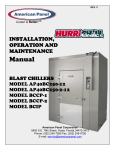
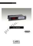
Display Case
FHG 2L & FHG 3L
Foster Refrigerator Environmental Management Policy
Product Support and Installation Contractors
Foster Refrigerator recognises that its activities, products and services can have an adverse impact upon the
environment.
The organisation is committed to implementing systems and controls to manage, reduce and eliminate its adverse
environmental impacts wherever possible, and has formulated an Environmental Policy outlining our core aims. A
copy of the Environmental Policy is available to all contractors and suppliers upon request.
The organisation is committed to working with suppliers and contractors where their activities have the potential to
impact upon the environment. To achieve the aims stated in the Environmental Policy we require that all suppliers
and contractors operate in compliance with the law and are committed to best practice in environmental
management.
Product Support and Installation contractors are required to:
1. Ensure that wherever possible waste is removed from the client’s site, where arrangements are in place all
waste should be returned to Foster Refrigerator’s premises. In certain circumstances waste may be disposed
of on the clients site; if permission is given, if the client has arrangements in place for the type of waste.
2. If arranging for the disposal of your waste, handle, store and dispose of it in such a way as to prevent its
escape into the environment, harm to human health, and to ensure the compliance with the environmental law.
Guidance is available from the Environment Agency on how to comply with the waste management ‘duty of
care’.
3. The following waste must be stored of separately from other wastes, as they are hazardous to the environment:
refrigerants, polyurethane foam, oils.
4. When arranging for disposal of waste, ensure a waste transfer note or consignment note is completed as
appropriate. Ensure that all waste is correctly described on the waste note and include the appropriate six-digit
code from the European Waste Catalogue. Your waste contractor or Foster can provide further information if
necessary.
5.
Ensure that all waste is removed by a registered waste carrier, a carrier in possession of a waste management
licence, or a carrier holding an appropriate exemption. Ensure the person receiving the waste at its ultimate
destination is in receipt of a waste management licence or valid exemption.
6. Handle and store refrigerants in such a way as to prevent their emission to atmosphere, and ensure they are
disposed of safely and in accordance with environmental law.
7. Make arrangements to ensure all staff who handle refrigerants do so at a level of competence consistent with
the City Guilds 2078 Handling Refrigerants qualification or equivalent qualification.
8. Ensure all liquid substances are securely stored to prevent leaks and spill, and are not disposed of to storm
drains, foul drain, surface water to soil.
Contents
Introduction
Technical Specification.
Temperature Controller
Controller Display and Symbols.
Setting the set point
Programming the controller.
Accessing the type “F” parameters
Accessing the type “C” parameters
Modifying the parameters
Procedure for setting the default parameter values
Classification of Parameters
Parameter Settings
Parameter Definitions
Spare Parts List
Wiring Diagrams
1
Page
2
2
3
3 to 4
4
4
4
4 to 5
5
5
6
6 to 7
8 to 13
13
14 to 17
Introduction
The display case are manufactured in two formats FHG 2L, 2 doors, and the FHG 3L, three doors.
There are also Multiplex options that are a combination of two FHG 2L cases to make a FHG 4L or a combination
of the FHG 2L and FHG 3L to make a FHG 5L.
Technical Specification.
Model
External Dimensions (m)
Internal Dimensions (m)
No. of Shelves
Shelf capacity (each)
Door System
Refrigeration System
Compressor
Height (m)
Width (m)
Depth (m)
Height (m)
Width (m)
Depth (m)
Kg
2 Door
2100
1684
900
1354
1564
550
12
40
Schott
Up to Aug
2004
Hitachi
FL200 DL
400v 3 phase
From Aug
2004
Hitachi
DS 183651
230v 1 phase
3 Door
2100
2463
900
1354
2343
550
18
40
Schott
4 Door
2100
3254
900
1354
3128
550
24
40
Schott
5 Door
2100
4035
900
1354
3907
550
30
40
Schott
Hitachi FL200
DL
400v 3 phase
(x 2)
Hitachi
DS 183651
230v 1 phase
(x 2)
R404A
2500 grms
R404A
3500 grms
Vaporisation
Hot Gas
Defrost Type
Hot Gas and
Electric (1 kW)
Hot Gas
Hot Gas and
Electric
( 1.5 kW)
R404A
2500 grms
(x 2)
Hot Gas
Hot Gas and
Electric
(2.1kW)
230/1/50
400/3/50
230/1/50 X 2
16A
Carel
PB00F0HB10
16A
Carel
PB00F0HB10
16A
Carel
PB00F0HB10
Hitachi
FL300DL
400 3 Phase
(x 2)
R404A
2500 grms +
3500 grms
Hot Gas
Hot Gas and
Electric
(2.5 kW)
400/3/50 +
230/50/1
16A
Carel
PB00F0HB10
140
266
132
210
380
198
2760
2660
5.1
280
522
264
350
646
330
Hitachi
FL300DL
400 3 Phase
Refrigerant
Electrical supply
Electrical Supply Capacity
Controller
Heat loads & Consumption
Lighting
Door frame heaters
Fan motors
Compressor consumption
Compressor Duty
Compressor Current
Watts
Watts
Watts
Watts
Watts
A
2
Temperature controller
It is strongly advised that before adjusting any Service Parameters a thorough understanding of the
following instructions should be obtained.
Carel PB00F0HB10
15
14
13
1
2
3
4
9
10
12
11
16
17
18
19
5
6
7
8
Controller Display and Symbols.
NOTE: When the buttons are pressed a brief audible signal is emitted; this signal can not be disabled.
1.
HACCP: Pressing this button displays a sub menu used to access the HACCP parameters (not used by
Foster)
2.
ON/OFF: When pressed for more than 5 seconds switches the controller on/off. When OFF the controller
display alternates between “OFF” and the air temperature as read by the air probe.
3.
PRG/MUTE:
Mutes the audible alarm and deactivates the alarm relay.
: If pressed for more than 1 second the during the reception of the automatic network address
assignment request package, starts the address assignment procedure (not used by Foster).
: If pressed for more than 5 seconds, allows access to the menu for setting the “F” (frequent)
parameters.
: If pressed for more than 5 seconds together with,
allows access for setting the “C”
(configuration) Parameters.
: If pressed for more than 5 seconds when switching the instrument ON, activates the procedure for
setting the default parameter values.
: If pressed for more 5 seconds together with,
resets any active alarm with manual reset (the message
‘rES ‘ indicates that the alarm has been reset); any delays relating to the alarms are re-activated.
4.
UP/CC: If pressed for more than 5 seconds, activates/deactivates the continuous cycle operation (the
message ‘ccE’ and ‘ccE’ indicate, respectively, the start and end of the continuous cycle request).
: If pressed together with,
for more than 5 seconds, starts the report printing procedure (provided the
printer interface is connected to the controller).
: If pressed for more than 5 seconds together with,
resets any active alarm with manual reset (the
message ‘rES ‘ indicates that the alarm has been reset); any delays relating to the alarms are reactivated.
5.
Light: If pressed for more than 1-second activates/deactivates auxiliary output 2.
6.
AUX: If pressed for more than 1-second activates/ deactivates auxiliary output 1.
7.
DOWN/DEF: If pressed for mare than 5 seconds, activates/deactivates a manual defrost (the message
‘dFb’ and dFE’ indicate, respectively, the start and end of defrost).
8.
SET: If pressed for more than 1 second displays and/or sets the set point.
: If pressed for more than 5 seconds together with
, accesses the menu for setting the type ”C”
(configuration) parameters.
: If pressed together with
for more than 5 seconds, starts the report printing procedure (provided the
printer interface is connected to the controller).
3
9.
Compressor: Illuminated when the compressor is running. Flashes when the activation of the compressor
is delayed by safety times.
10.
FAN: Illuminated when the fan starts. Flashes when the activation of the fan is prevented due to external
disabling or procedures in progress.
11.
DEFROST: Illuminated when defrost is activated. Flashes when the activation of the defrost is prevented
due to external disabling or procedures in progress.
12.
AUX: Illuminated when the auxiliary output (1 and/or 2) selected as AUX is activated.
13.
ALARM: Illuminated following the activation of the external digital input alarm. Flashes in the event of
alarms during normal operation (e.g. high /low temperature) or in the event of alarms from an external
digital input, immediate or delayed.
14.
CLOCK: Illuminated if at least one timed defrost has been set. On start up comes ON for a few seconds to
indicate that the Real Time Clock is active.
15.
LIGHT: Illuminated when the auxiliary output (1 and /or 2) is selected as the LIGHT is activated.
16.
SERVICE: Flashes in the event of a malfunction, for example EPROM errors or probe faults.
17.
DISPLAY: Displays the temperature in the range –50 to +150°C. the temperature is displayed to the tenth
of a degree between –19.9 and + 19.9°C. the display of the tenths can be disabled by setting the related
parameter.
18.
HACCP: Illuminated if the HACCP function is enabled. Flashes when there are hew HACCP alarms stored
(HA and/or HF alarm shown on the display).
19.
CONTINUOUS CYCLE:Illuminated when the CONTINUOUS CYCLE function is activated. Flashes if the
activation of the function is prevented due to external disabling or procedures in progress (e.g. minimum
compressor OFF time).
Setting the set point.
To display the set point proceed as follows:
1.
Press
for more than 1 second to display the set point.
2.
To increase the set point press
reached.
3.
To confirm the value press
or to decrease the set point press
until the desired value is
.
Programming the controller.
The parameters can be modified using the front keypad.
The operating parameters are divided into two families: Frequent parameters (type “F”) and configuration
parameters (type “C”).
Access to the configuration parameters is protected by a password that prevents unwanted modification or access
by unauthorised persons.
Accessing the type “F” parameters.
Press
for more than 5 seconds (if an alarm is active, the buzzer is muted), the display shows the code of the
first modifiable type “F” parameter.
Accessing the type “C” parameters.
1.
Press
and
together for more than 5 seconds; the display will show the number “00”.
2.
Press
until the display shows “22” ( the code allows access to the parameters)
4
3.
Confirm by pressing
.
4.
The display shows the code of the first modifiable type “C” parameter.
Modifying the parameters.
After having accessed the parameters, either type “C” or type “F”, proceed as follows.
1.
Press
or
until the parameter to be modified is reached, when scrolling through an icon appears on
the display indicating the category the parameters belong to.
2.
Alternatively, press
modified.
3.
Scroll through the menu using the
or
buttons, the display shows the codes of the various
categories of the parameters, accompanied by the display of the corresponding icon (if present).
4.
Once having reached the desired category, press
to move directly to the first parameter in the
category.
(If there are no visible parameters in the selected category pressing
will have no effect.)
5.
At this point continue to scroll through the parameters until reaching the parameter to be modified, or return
to display a menu that is used to quickly access the group of parameters to be
to the “Categories” menu by pressing
for one second.
6.
Press
to display the associated value.
7.
Increase or decrease the value by pressing
been reached.
8.
By pressing
9.
Repeat the operations point 1 or point 2.
10.
If the parameter has sub-parameters, press
11.
Press
or
12.
Press
to display the associated value.
13.
Increase or decrease the value by pressing
been reached.
14.
By pressing
15.
Press
or
buttons respectively, until the desired value has
this will temporarily save the new value and return to displaying the parameter code.
to display the first sub-parameter.
to display all of the sub-parameters.
or
buttons respectively, until the desired value has
this will temporarily save the new value and return to displaying the sub-parameter code.
to return to displaying the parent parameter.
Procedure for setting the default parameter values
To set the default parameter setting proceed as follows.
1.
Switch the instrument off.
2.
Press and hold the
button
3.
Whilst holding the
display.
button switch the instrument on again until the message ”_std_” is shown on the
Note: the standard default values are set for parameters “C” and “F”, on completion it is necessary to change the
respective parameters as detailed in the parameter settings table on page 6 and 7.
5
Classification of Parameters
The parameters, as well as being divided into type, are also grouped into logical categories identified by the initial
letters or symbols of such parameters. The following table lists the categorise and the corresponding letters.
Parameter
Category
Text
/
Temperature probe parameters
‘Pro’
r
Temperature control parameters
‘CtL’
c
Compressor safety time and activation parameters
‘CMP’
d
Defrost parameters
‘dEF’
A
Alarm parameters
‘ALM
F
Fan parameters
‘Fan’
H Configuration General configuration parameters (addresses, enabling, etc….)
‘CnF’
H HACCP
HACCP parameters
‘HcP’
RTC
RTC parameters
Icon
‘rtc’
Parameter Settings
The highlighted section indicate the Foster settings
Unit of
Measure
flag
flag
°C/°F
°C/°F
°C/°F
°C/°F
No
Code
Parameter
1
2
3
4
5
6
7
8
9
10
11
12
13
14
15
/2
/3
/4
/5
/6
/tI
/tE
/P
/A2
/A3
/A4
/C1
/C2
/C3
/C4
Measurement stability
Probe display reaction
Virtual probe
Select °C or °F
Decimal point
Display on internal terminal
Display on external terminal
Select type of probe
Configuration of probe 2
Configuration of probe 3
Configuration of probe 4
Calibration of probe 1
Calibration of probe 2
Calibration of probe 3
Calibration of probe 4
16
17
18
19
20
21
22
23
24
25
St
rd
r1
r2
r3
r4
r5
rt
rH
rL
Temperature set point
Controller differential
Minimum SET allowed
Maximum SET allowed
Operating mode
Automatic night time set point variation
Enable temperature monitoring
Temperature monitoring interval
Maximum temperature read
Minimum temperature read
26
27
28
29
30
31
32
33
34
c0
c1
c2
c3
c4
cc
c6
c7
c8
Compressor and fan start delay at start up
Minimum time between successive starts
Minimum compressor OFF time
Minimum compressor ON time
Duty Setting
Continuous cycle duration
Alarm bypass after continuous cycle
Maximum pump down (PD) time
Compressor start delay after opening PD valve
6
Default
FHG2l
FHG3L
4
0
0
0
0
1
0
0
2
0
0
0.0
0.0
0.0
0.0
4
0
0
0
0
1
0
0
2
0
0
0.0
0.0
0.0
0.0
4
0
0
0
0
1
0
0
2
0
0
0.0
0.0
0.0
0.0
°C/°F
°C/°F
°C/°F
°C/°F
flag
°C/°F
flag
hours
°C/°F
°C/°F
0.0
2.0
-50
60
0
3.0
0
-
0.0
4.0
-26
-15
0
3.0
0
-
0.0
4.0
-26
-15
0
3.0
0
-
min
min
min
min
min
hours
hours
min
sec
0
0
0
0
0
0
2
0
5
0
1
0
0
80
0
2
0
5
0
1
0
0
80
0
2
0
5
35
36
37
c9
c10
c11
Enable autostart with PD operation
Select Pd by time or pressure
Delayed compressor delay
flag
flag
sec
0
0
4
0
0
4
0
0
4
38
39
40
41
42
43
44
45
46
47
48
49
50
51
52
53
54
55
56
57
58
d0
dI
dt1
dt2
dp1
dp2
d3
d4
d5
d6
dd
d8
d9
d/1
d/2
dC
d10
d11
d12
dn
dH
Type of defrost
Interval between defrosts
End defrost temperature, evaporator.
End defrost temperature, aux. evaporator
Maximum defrost duration, evaporator
Maximum defrost duration, aux. Evaporator
Defrost start delay
Enable defrost at start up
Defrost delay at start up
Display off during defrost
Dripping time after defrost
Bypass alarm after defrost
Defrost priority over compressor protection
Display defrost probe
Display defrost probe
Base time for defrost
Compressor running time
Running time temperature threshold
Advanced defrost
Nominal defrost time
Proportional factor for variation in ‘dI’
flag
hours
°C/°F
°C/°F
min
min
min
flag
min
min
hours
flag
°C/°F
°C/°F
flag
hours
°C/°F
-
0
8
4.0
4.0
30
30
0
0
0
1
2
1
0
0
0
1.0
0
65
50
1
6
20.0
4.0
20
30
0
0
0
1
1
1
0
0
0
1.0
0
65
50
1
6
20.0
4.0
20
30
0
0
0
1
1
1
0
0
0
1.0
0
65
50
59
60
61
62
63
64
65
66
67
68
69
70
71
72
73
A0
A1
AL
AH
Ad
A4
A5
A6
A7
A8
Ado
Ac
AE
Acd
AF
Alarm and fan differential
Type of threshold for ‘AL’ and ‘AH’
Low temperature alarm threshold
High temperature alarm threshold
Low and high temperature alarm delay
Configuration of digital input 1
Configuration of digital input 2
Stop compressor from external alarm
External alarm detection delay
Enable alarms ‘Ed1’ and Ed2’
Door switch light management mode
High condenser temperature alarm
High condenser alarm temperature differential
High condenser temperature alarm delay
Off time with light sensor
°C/°F
flag
°C/°F
°C/°F
min
min
min
flag
flag
°C/°F
°C/°F
min
sec
2.0
0
0.0
0.0
120
0
0
0
0
0
0
70.0
5.0
0
0
4.0
0
0.0
0.0
120
0
0
0
0
0
0
70.0
5.0
0
0
4.0
0
0.0
0.0
120
0
0
0
0
0
0
70.0
5.0
0
0
74
75
76
77
78
F0
F1
F2
F3
Fd
Fan management
Fan start temperature
Fan off with compressor off
Fans in defrost
Fans off after dripping
flag
°C/°F
flag
flag
min
0
5.0
1
1
1
0
5.0
0
1
1
0
5.0
0
1
1
79
80
81
82
83
84
85
86
87
H0
H1
H2
H3
H4
H5
H6
H7
HPr
Serial address
Function of relay 4
Disable key / infra red
Remote control enabling code
Disable buzzer
Function of relay 5
Lock out buttons
Select PD by time or pressure
Print profile
flag
flag
flag
flag
-
1
1
1
0
0
3
0
0
0
30
2
1
0
0
3
0
0
0
30
2
1
0
0
3
0
0
0
Note: The total number of parameters is 105. For ease of set up Foster only use the ones listed. The
remaining are not used and adjustment is not recommended.
7
Parameter Definitions
/2
Measurement stability.
Defines the coefficient used to stabilise the temperature reading.
/3
Probe display rate
Sets the rate at which the temperature display is updated.
/4
Probe average (Virtual probe)
Used to choose whether to control the temperature based solely on the room probe reading, or
alternatively whether to refer to the average of the room probe S1 and probe 2(S2, see parameter /A2).
/5
Select °C or °F
Defines the unit of measure in degrees centigrade or Fahrenheit.
/6
Decimal point
Used to enable or disable the displaying of the temperature with the resolution to the tenth of a degree
between –20 and +20.
/tI
Probe displayed by instrument
Select the probe to be displayed by the instrument.
Warning: Control is always based on the virtual control probe.
/tE
Probe displayed on external terminal
Selects the probe to be displayed on the remote terminal.
/P
Select type of probe
Used to select the type of probe for temperature measurement.
Default. /P = standard NTC probe with range –50 to +90°C.
/A2
Configuration of probe 2
Used to configure the operating mode of probe 2.
Default: /A2 =2 = Defrost probe.
/A3
Configuration of probe 3
Used to configure the operating mode of probe 3.
Default: /A3 = 0 = Probe 3 absent.
/A4
Configuration of probe 43
Used to configure the operating mode of probe 43.
Default: /A4 = 0 = Probe 4 absent.
/C1
/C2
/C3
/C4
Calibration or offset probe 1
Calibration or offset probe 2
Calibration or offset probe 3
Calibration or offset probe 4
These parameters are used to correct the temperature by the probes using an offset.
Example: To decrease the temperature measured by probe 1 by 2.3 degrees, set /C1 = -2.3.
St
Set point
Establishes the controller set point.
Default: St = 0.0
rd
Control delta
Establishes the value of the differential, or hysteresis, used to control the temperature.
Default: rd = 2.0. Foster setting: rd = 4.0
r1
Minimum allowed set point
Determine the set point minimum value.
Default: r1 = -50. Foster setting: r1 = -26.
r2
Maximum allowed set point.
Determine the set point maximum value.
Default: r2 = +60. Foster setting: r2= -15.
8
r3
Operating mode
The controller can work as a thermostat and defrost controller (r3 = 0), or as a simple thermostat in direct
operation (r3 = 1), or as a simple thermostat in Reverse- cycle operation (r3 = 2).
Default setting: r3 = 0.
r4
Automatic variation of the set point in night time operation.
Default: 3.0. Not used by Foster
r5
rt
rH
rL
Enables minimum and maximum temperature monitoring.
Effective interval for monitoring the maximum and minimum temperature.
Maximum temperature measured in the interval rt.
Minimum temperature measured in the interval rt.
These parameters are used for recording the temperature. Not used by Foster.
c0
Compressor and fan start delay (if fan relay present) on start up.
When the controller is switched on the compressor and evaporator fans start after a delay (in minutes)
equal to the value set for this parameter.
Default: c0 = 0.
c1
Minimum time between two successive starts of the compressor.
Sets the minimum time (in minutes) that must elapse between two starts of the compressor irrespective of
the temperature and the set point. Setting this parameter limits the number of starts per hour.
Default: c1 = 0. Foster setting c1 = 1.
c2
Minimum compressor OFF time.
Sets the minimum time (in minutes) that the compressor must remain OFF. The compressor is not started
again until the minimum time selected (c2) has elapsed from when it last stopped.
Default: c2 = 0. No minimum OFF time is set.
c3
Minimum compressor ON time.
Sets the minimum running time for the compressor.
Default: c3 = 0. No minimum running time selected.
c4
Duty setting
If the virtual control probe fault alarm occurs (indicating a probe fault) the compressor unable to operate
based on temperature will run on a timed bases equal to the value set in c4 with a fixed OFF time of 15
minutes.
Default: c4 = 0 minutes. Foster setting c4 = 80 minutes.
cc
Continuous cycle duration.
The time (in hours) that the compressor operates continuously to lower the temperature, even below the
set point
Default: cc = 0 = the continuous cycle is disabled.
c6
Alarm bypass after continuous cycle.
The time in hours that the temperature alarm is deactivated after a continuous cycle.
Default: c6 =2 hours.
c7
Maximum pump down time.
Not used by Foster.
c8
Compressor start delay after opening PD valve.
Not used by Foster.
Default: c8 = 5
c9
Enable autostart function with PD operation.
Not used by Foster
Default: c9 = 0
c10
Select pump down by pressure or time.
Not used by Foster
Default: c10 = 0
9
c11
Delayed compressor delay
Not used by Foster
Default: c11 = 4
d0
Type of Defrost
Sets the type of defrost required.
Default: d0 = 0. Foster setting d0 = 1. Hot gas defrost terminated by evaporator probe or in the event of
probe failure by time (see dP1).
dI
Interval between defrosts.
The defrosts are performed periodically at an interval equal to the value of ‘dI’ in hours.
The interval is cyclical and is maintained if the controller is turned OFF, when the controller is turned back
ON a defrost will occur if the interval was exceeded.
Default: dI = 8. Foster setting dI = 6.
dt1
End defrost temperature, evaporator probe.
The evaporator probe termination temperature, in the event of a probe failure the defrost will be terminated
by time (see dP1).
Default dt1 = 4.0. Foster setting dt1 = 20.0.
dt2
End defrost temperature, auxiliary evaporator.
Not used by Foster.
Default: dt2 = 4.0.
dP1
Maximum defrost duration, Evaporator.
Maximum time, in minutes, for defrost in the event of evaporator probe failure.
Default: dP1 = 30. Foster setting dP1 = 20.
dP2
Maximum defrost duration, auxiliary evaporator.
Not used by Foster
Default: dP2 = 30.
d3
Defrost start delay
Not used by Foster.
Default: d3 = 0.
d4
Enable defrost at start up.
Activates a defrost when the defrost is switched on.
0 = no defrost performed when the instrument is switched on
Default: d4 = 0.
d5
Defrost delay at start up.
Not used by Foster.
Default: d5 = 0.
d6
Display during defrost.
1 = The last temperature read prior to the start of the defrost remains on the display. The display returns to
displaying the temperature when the set point is achieved.
Default: d6 = 1.
dd
Dripping time after defrost.
The time, in minutes, that the evaporator fans are delayed after defrost to allow for the evaporator to drip.
Default: d6 = 2. Foster setting d6 = 1.
d8
Bypass alarms after defrost.
The time, in hours, that the high temperature alarms is disabled for after the end of the defrost cycle
Default: d8 = 1.
d9
Defrost priority over compressor protection.
Not used by Foster
Default: d9 = 0
10
d/1
Display defrost probe.
Displays the value measured by the defrost probe.
Once d/1 has been selected press the
probe.
button to display the temperature measured by the defrost
d/2
Display defrost probe 2 reading.
Not used by Foster.
dC
Base time for defrost.
Not used by Foster
Default: dC = 0.
d10
Compressor running time.
Not used by Foster
Default: d10 = 0.
d11
Running time temperature threshold.
Not used by Foster
Default: d11 = 1.0.
d12
Advanced defrost.
Not used by Foster
Default: d12 = 0.
dn
Nominal defrost time.
Indicates the average duration of the defrost in normal operating conditions expressed as a percentage in
accordance with dP1.
Default: dn = 65. Example dn at 65% of dP1 20 minutes = 13 minutes nominal defrost duration.
dH
Proportional factor for variation in ‘dI’.
Default: dH = 50.
A0
Alarm and fan differential.
Default: A0 = 2.0. Foster setting A0 = 4.0.
A1
Type of threshold for ‘AL’ and ‘AH’.
Used to select if the values of parameters ‘AL and ‘AH’ are absolute threshold or relative to the value of the
set point.
Default: A1 = 0 = ‘AL’ and ‘AH’ are relative thresholds.
AL
Low temperature alarm threshold.
Not used by Foster.
Default: AL = 0 = alarm disabled.
AH
High temperature alarm threshold.
Not used by Foster.
Default: AH = 0 = alarm disabled.
Ad
Low and high temperature alarm delay.
Indicates the time in minutes that the alarm from when the alarm was signalled.
Default: Ad = 120.
A4
Configuration of digital input 1.
Not used by foster.
Default: A4 = 0.
A5
Configuration of digital input 2.
Not used by foster.
Default: A5 = 0.
A6
Stop compressor from external alarm.
Not used by Foster
11
A7
Default: A6 = 0.
External alarm detection delay.
Not used by foster
Default: A7 = 0.
A8
Enables alarm ‘Ed1’ and ‘Ed2’.
Not used by Foster.
Default: A8 = 0 = alarms ‘Ed1’ and ‘Ed2’ disabled.
Ado
Door switch light management mode.
Not used by Foster.
Default: Ado = 0.
Ac
High condenser temperature alarm.
Not used by Foster.
Default: Ac = 70.0.
AE
High condenser alarm temperature differential.
Not used by Foster.
Default: AE = 5.0.
Acd
High Condenser temperature alarm delay.
Not used by Foster.
Default: Acd = 0.
AF
Off time with light sensor.
Not used by Foster.
Default: AF = 0.
F0
Fan management.
F0 = Fan runs all of the time, for fans during defrost see ‘F3’.
Default: F0 = 0.
F1
Fan start temperature.
Used in conjunction with ‘F0’ when ‘F0’ = 1.
Default: F0 = 5.0. Fans remain ON while the evaporator is 5 degrees colder than the room temperature.
F2
Fans off with compressor off.
Used in conjunction with ‘F0’.
Default: F2 = 1. Foster setting F2 = 0 fans are always ON (F0 =0).
F3
Fans in defrost.
Used to determine if the fans operate or not during defrost.
Default: F3 = 1. Fans do not operate during defrost.
Fd
Fans off after dripping.
Fans can be stopped for a further period, in minutes, after defrost beyond what has been set in ‘dd’.
Default: Fd = 1 = 1 additional minute dripping time.
H0
Serial address.
Used to assign an address to the instrument so that it responds to when connected to a supervisory or
telemaintenance system.
Default: H0 = 1. Foster setting H0 = 30.
H1
Function of relay 4.
Auxiliary output used to power the doorframe lighting and frame heater.
Default: H1 = 1. Foster setting H1 = 2.
H2
Disable keypad / infra red.
Can be used to inhibit some functions relating to the use of the keypad.
Default: H2 = 1 = all enabled.
H3
Remote control enabling code.
Assigns an access code to the remote control if fitted.
Not used by Foster.
12
H4
Default: H3 = 0.
Disable buzzer.
H4 = 0 buzzer enabled. H4 = 1 buzzer disabled.
Default: H4 = 0.
H5
Function of relay 5.
Not used by Foster.
Default: H5 = 3.
H6
Lock out Buttons.
Not used by Foster.
Default: H6 = 0.
H7
Select Keypad.
Used to select the type of keypad on the controller.
Default: H7 = 0. Use the standard controller.
HPr
Print Profile.
Not used by Foster.
Default: HPr = 0 = printing report disabled.
Note:
Although there are further parameters in the controller these are not used by Foster and should be
left with the standard default settings.
Spare Parts List
Item
Compressor
Compressor
Compressor
Condenser coil
Cond Fan Motor
Cond Fan Blade
Cond Fan Shroud
Condenser coil
Condenser Fan Motor
Drier
Liquid Receiver
HP Switch
LP Switch
Sight Glass
Solenoid Valve
Vaporiser Tray Heater
Vaporiser Tray
Defrost Klixon
Defrost Heaters
Evaporator Coil
Evaporator Coil
Fan Motor
Expansion Valve Body
Expansion Valve
Orifice
Orifice
Control Panel
Control Panel
Control Panel
Controller
Interface
Probes
Isolator
16 AMP Contactor
R1/ R2 Relay
Description
Scroll Compressor FL200DL 400/3/50
Used up to August 2004
Scroll Compressor DS183651 230/1/50
Used from August 2004
Scroll Compressor FL300DL 400/3/50
Condenser Set LUVE STVF370
MOTOR 11W/S
Blade 254-26-5A
SHROUD CF-27
Condenser Coil BC6013/115
5136 Grid Mount 16W
DML 053S
VLR 122637 3/8 Sweat
Set at 28 BAR
Set at 4PSI
3/8" SGN-105
EVR6 32F1212
Copper Coil
Container White Part 758 140 81 Fish
Thermal Cutout 1/2" Autoreset
Heater Rod PGC 94 (2 off per coil)
BC6013/114 FHG2L
BC6013/114 FHG3L
5133 Ring 10W 200mm
TES2-NL68Z34300/68
Valve Exp Solder Adaptor 68-2
NO 03 68-209300/68-20
NO 02 68-2092/68-2072
FHG2L Three Phase Complete
FHG2L Single Phase Complete
FHG3L Three Phase Complete
Carel PB00F0HA10
RS 482 IROPZ48500
NTC 030WP00 IP68 3 metre
KG10BT214/04E 20AMP 4 pole
KN S1010-C240- 300
Omron G7L-1A-T 30Amp 1 Pole
13
Part Number
FHG2L
00-555449
X
00-555450
X
00-555451
00-555448
16240058
16240059
16240060
00-555474
15470027
00-555389
15482010
00-555386
00-555387
15483015
15451215
TBA
00-554948
15243602
15843181
00-555475
00-555476
00-599687
15450386
15450910
15451105
15451104
01-233868-01
01-233867-01
01-233869-01
16240051
16240053
16240052
16240211
15841105
15490420
FHG3L
X
X
X
X
X
X
X
X
X
X
X
X
X
X
X
X
X
X
X
X
X
X
X
X
X
X
X
X
X
X
X
X
X
X
X
X
X
X
X
X
X
X
X
X
X
X
X
X
X
MCB
Siemens 5SY6316 –8 TP 16 Amp 3 Pole
Wiring diagrams
The drawings numbers for the display cases are as follows:
FHG2L - 2 door unit single phase
FHG2L - 2 door unit three phase
FHG3L - 3 door unit three phase
00-233867-02
00-233868-02
00-233869-02
14
16240209
X
X
15
FHG2L - 2 door unit single phase
00-233867-02
FHG2L - 2 door unit three phase
00-233868-02
FHG3L - 3 door unit three phase
1
00-233869-02
Foster European Operations
France
Foster Refrigerator France SA
Tel: (33) 01 34 30 22 22. Fax: (33) 01 30 37 68 74.
Email: [email protected]
Germany
Foster Refrigerator Gmbh,
Tel: (49) 2333 839375. Fax (49) 2333 839377.
Email: [email protected]
Foster Refrigerator
Oldmedow Road
Kings Lynn
Norfolk
PE30 4JU
Tel: 01553 691122
Fax: 01553 691447
Website: www.fosterrefrigerator.co.uk
Email: [email protected]
a Division of ‘ITW (UK) Ltd’
DISPCASE/SM/10/04