1
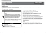
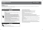
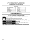
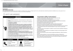
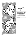
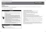
(1,1) -1- 599496B OB30Aerotech installA2 USCA.indd 4/6/09 9:40:11 AM
Installation instructions
Aerotech oven
US CA
OB30 models
Important!
SAVE THESE INSTRUCTIONS
The models shown in this document may not be available in all markets and are subject to change at any time. For current details about model and specification availability in your country, please visit our local
website listed at the end of this document or contact your local Fisher & Paykel dealer.
1 SAFETY AND WARNINGS
WARNING!
Always disconnect the oven from
the mains electricity supply
before carrying out any
maintenance operations or
repairs.
Failure to do so may result in
electrical shock or death.
SINGLE
OVEN
MODELS
Electrical hazard
DOUBLE
OVEN
MODELS
WARNING!
Very Heavy
409 lb
186 kg
Do not attempt to lift this
product unassisted.
Lifting unassisted may
cause serious injury.
242 lb
110 kg
WARNING!
Cut hazard
Take care - panel edges are sharp.
Failure to use caution could result in injury or cuts.
Important safety instructions!
Save these instructions for the local inspectors’ use.
To avoid hazard, follow these instructions carefully before installing or using this product.
Please make this information available to the person installing the product as it could reduce your
installation costs.
This oven is to be installed and connected to the electricity supply only by an authorized person.
If the installation requires alterations to the domestic electrical system, call a qualified electrician. The
electrician should also check that the socket cable section is suitable for the electricity drawn by the oven.
The oven must be grounded.
To connect the oven to the mains, do not use adapters, reducers or branching devices as they can cause
overheating and burning.
Installation must comply with your local building and electricity regulations.
Failure to install the oven correctly could invalidate any warranty or liability claims.
Before you install the oven, please make sure that
The oven will rest on a surface that can support its weight.
The countertop and oven cavity are square and level, and are the required dimensions.
The height from the floor suits the user.
The oven door can open fully without obstruction.
Electrical requirements
Connect oven with copper wire only.
Do not cut the conduit.
A U.L. listed conduit connector must be provided at the junction box.
Do not ground to a gas pipe.
Do not have a fuse in the grounding or neutral circuit.
Fuse both sides of the line.
A time delay fuse or circuit breaker is recommended. If using a time delay fuse, then fuse both sides of the
line.
Flexible armored cable from the appliance should be connected directly to the junction box.
Connect directly to the fused disconnect (or circuit breaker box) through flexible, armored or non-metallic
sheathed, copper cable (with grounding wire).
If codes permit and a separate grounding wire is used, it is recommended that a qualified electrician
determine that the grounding path and wire gauge are in accordance with local codes.
Do not use an extension cord with this appliance.
When you install the oven
Do not seal the oven into the cabinetry with silicone or glue. This makes future servicing difficult. Fisher &
Paykel will not cover the costs of removing the oven, or of damage caused by this removal.
Use the supplied screws to secure the oven to the cabinetry. Do not over-tighten the screws.
Do not stand on the door, or place heavy objects on it.
Do not lift the oven by the door handle.
Take extra care not to damage the lower trim of the oven.
(1,2) -1- 599496B OB30Aerotech installA2 USCA.indd 4/6/09 9:40:11 AM
2 PRODUCT AND CABINETRY DIMENSIONS
3 PRODUCT AND CABINETRY DIMENSIONS
Single oven models
Double oven models
II
I
II
I
C
E
B
C
E
K
B
J JI
J JI
K
A
D
A
D
H
Proud install
F
Flush install
(16-20 mm)
G
Proud install
5⁄8-13⁄16”
5⁄8-13⁄16”
H
(16-20 mm)
G
Flush install
5⁄8-13⁄16”
(16-20 mm)
F
5⁄8-13⁄16”
(16-20 mm)
G
G
1⁄8” (2.5 mm)
Installation diagrams for illustration purposes only
overall height of product
27 1⁄16” (688)
overall width of product
29 ¾” (757)
overall depth of product (without handle)
23 15⁄16” (608)
height of chassis
26 ¾” (675)
width of chassis
28 ¼” (718)
depth of chassis
22 7⁄16” (570)
depth of oven frame and control panel (excl. knobs)
1 ½” (38)
depth of oven door (open) (measured from front of oven frame)
20 7⁄8” (530)
minimum inside width of cavity
28 ½” (724)
overall width of cabinetry
30” (762)
inside height of cavity
26 13⁄16” (681)
overall height of cabinetry
27 5⁄16” (693)
minimum inside depth of cavity
Proud install 22 5⁄8” (575)
Flush install 24 1⁄8” (613)
Note: If installing a cooktop above the oven, ensure adequate clearance is provided for the cooktop as per the
cooktop manufacturer’s instructions.
1⁄8” (2.5 mm)
Ensure the cavity is completely sealed with no gaps
Product and cabinetry dimensions (inches (mm))
OB30 D
models
A
B
C
D
E
F
G
H
I
II
J
JI
K
Ensure the cavity is completely sealed with no gaps
OB30 S
models
Product and cabinetry dimensions (inches (mm))
1⁄8” (2.5 mm)
1⁄8” (2.5 mm)
A
B
C
D
E
F
G
H
I
II
J
JI
K
overall height of product
overall width of product
overall depth of product (without handle)
height of chassis
48 7⁄16” (1230)
29 ¾” (757)
23 15⁄16” (608)
47 15⁄16” (1217)
width of chassis
28 ¼” (718)
depth of chassis
22 7⁄16” (570)
depth of oven frame and control panel (excl. knobs)
1 ½” (38)
depth of oven doors (open) (measured from front of oven frame)
20 7⁄8” (530)
minimum inside width of cavity
28 ½” (724)
overall width of cabinetry
30” (762)
inside height of cavity
48 1⁄8” (1222)
overall height of cabinetry
48 5⁄8” (1235)
minimum inside depth of cavity
Proud install 22 5⁄8” (575)
Flush install 24 1⁄8” (613)
(2,1) -1- 599496B OB30Aerotech installA2 USCA.indd 4/6/09 9:40:11 AM
4 UNPACK THE OVEN AND REMOVE THE DOOR(S)
Double models featured for illustration purposes only
A
B
1
3
4
1
Important!
Ensure you remove
the long trim from
the packaging
2
4
5 ELECTRICAL CONNECTION TO JUNCTION BOX
A
cable from
power supply
red wires
red wires
Junction box location
for: undercounter
installation
Junction box
location for:
wall installation
OB30 Double
Max. current draw:
Max. load:
1
2
3
4
5
6
Disconnect the power supply.
Remove the junction box cover.
Connect the oven cable to the junction box
through the U.L.-listed conduit connector.
Connect the two black wires together with
twist-on connectors.
Connect the two red wires together with
twist-on connectors.
Connect electrical connection according to
local codes and ordinances.
box
box
OB30 Single
Max. current draw:
Max. load:
19.4 A
4.6 kW
38.3 A
9.2 kW
If local codes permit connecting the cabinetgrounding conductor to the neutral white wire
in the junction box:
7a Connect the factory-taped green and white oven
cable wires to the neutral (white) wire in the
junction box.
8a Replace the junction box cover.
white
wires
black
wires
Nameplate
white and green
grounding oven
wires - factory
taped
UL - listed
conduit connector
OR If local codes DO NOT PERMIT
connecting the cabinet-grounding
conductor to the neutral (white) wire in
junction box:
7b Separate the factory-taped green and white
oven cable wires.
8b Connect the white oven cable wire to the
neutral (white) wire in junction box.
9b Connect the green grounding oven cable
wire to a grounded wire in the junction box.
10b Replace the junction box cover.
OR
cable from
power supply
green grounding
oven wires
- factory taped
black
wires
UL - listed conduit
connector
If connecting to a four-wire electrical
system:
7c Separate the green and white oven cable wires.
8c Connect the white oven cable wire to the
neutral (white) wire in junction box.
9c Connect the green grounding oven cable wire
to the (green) grounding wire in the junction
box.
Do not connect the green grounding wire to
the neutral (white) wire in junction box.
10c Replace the junction box cover.
(2,2) -1- 599496B OB30Aerotech installA2 USCA.indd 4/6/09 9:40:11 AM
6 SECURE THE OVEN TO THE CABINETRY AND REFIT THE DOOR(S)
A
Ensure supplied spacer
is fitted between oven
and cabinetry
B
1
1
1
2
1
3
1
2
4
Take care not to
damage the lower trim
of the oven
2
7 FLUSH INSTALLATION ONLY - REPLACE THE LOWER TRIM WITH THE SUPPLIED LONG TRIM
A
B
Unscrew and remove the
installed lower trim
1
Replace with the
supplied long trim
Ensure the clips
on the long trim
locate into the
channels
1
2
Please turn over >
(1,1) -2- 599496B OB30Aerotech installA2 USCA.indd 4/6/09 9:42:48 AM
8 FINAL CHECKLIST
Make sure the appliance is level and securely fitted to the cabinetry and both
oven doors open and close freely.
Make sure all the internal packaging has been removed from the oven cavity.
Make sure all oven vents and openings are clear and are free of any
obstruction/damage.
Important!
Failure to make sure all oven vents are unobstructed may result in poor product performance.
Turn the power to the oven on. The clock should light up and flash 12:00pm.
Set the clock to the current time.
Turn the oven function knob to ‘Bake’ and the oven temperature knob to
350 oF (180 oC). Air should blow out of the vent at the bottom of the oven.
Inside the oven cavity, all three oven lights should come on. After five
minutes, open the oven door and the air inside should feel warm and the top
element should be glowing red.
Turn both the oven function knob and oven temperature knob back to OFF
and repeat for the other oven if the appliance is a double model.
9 TROUBLESHOOTING
If the appliance is not functioning correctly after installation, check the
following:
Check that the circuit breaker has not tripped or the fuse blown.
Make sure that the electrical connections have been correctly made.
Make sure that power is being supplied to the oven.
Make sure the voltage is correct across all phases.
If a problem occurs, consult the Troubleshooting section of the User Guide.
If after checking these points you still need assistance or parts, please refer to
the Service & Warranty book for warranty details and your nearest Authorized
Service Center, or contact us through our local website, listed below.
www.fisherpaykel.com
www.fisherpaykel.ca
599496B US CA 06.09