1
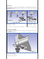
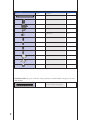
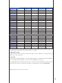
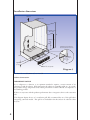
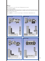
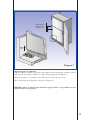
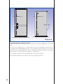
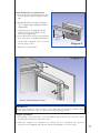
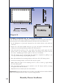
Integral Kit
Instructions
For Fisher & Paykel
Cabinet widths of
525, 635, 680, 790 mm wide
For curved door Models
Series B, C, D & G
Manual 814980
Updated August 2008
IMPORTANT
If your refrigerator has this type of front roller assembly as shown in diagram 1, then these are the
incorrect Built - in Kit instructions and dimensions you are following. Please use Built-in
Kit instructions 873918.
Diagram 1
Pre - June 1995
Post - June 1995
Kit Part Number 874561
H-Drawer Kit
876811
Kit Part Number 874560
H-Drawer Kit
876811
1985 G, H, A, J, K, L, M, P, Q, R series to June 1995
1995 R series July onward
Curved Door Models
If your refrigerator has this type of front roller assembly as shown in diagram 2, then these are
the correct instructions.
Diagram 2
Kit Part Number 814990
H-Drawer Kit
880800
1998 B series October onward
1
Parts supplied with Built-In kit
Part
Part No. 814990
Quantity
Description
Part no.
4
Rail slide
880791
4
Bracket slide
880792
2
Foot Integration
880793
8
Cap Elliptical for foot integration
880794
2
Spacers 20mm
880795
8
Screw A: (#8X 3/4 CSK POSI)
880796
2
Screw B: (#8X30 CSK POSI)
880797
8
Screw C: (#8X40 CSK POSI)
880798
4
Screw D: (#8X 1/2 PAN PH)
900373
1
Endcap Blank RH
883715
1
Endcap Blank LH
883716
5
Plug
880618
Ventilation Grill (Not part of the kit, order separately, recommended for integration of 790
wide models)
1
2
Ventilation grill
(Not part of the Kit order separately)
873917
Internal dimensions
Model 525
Width (A)
Depth (B)
Height (C)
600
600
840
C190, E150, RF190, RF150 600
600
1228
600
600
1228
C270, E210, RF270, RF210 600
600
1616
E249T, RF249T
600
600
1616
1200
E240B, RF240B
600
600
1616
811
E331T, RF331T
735
730
1446
971
E373/C373, E308
735
730
1446
E381T, RF381T
735
730
1616
1141
E372B, RF372B
735
730
1616
652
E411T, RF411T
735
730
1716
1240
E402B, RF402B
735
730
1716
652
E415H
735
730
1716
1240
E450/C450, E388
735
730
1716
E413T
780
730
1616
1141
E406B
780
730
1616
652
E440T
780
730
1716
1240
E442B
780
730
1716
652
E521T
890
730
1716
1240
E522B
890 (351/32")
730 (28 3/4")
1716 (67 9/16")
652 (2511/16")
P120, RF120
C170T, E169T, RF169T
PC/FC Centre line (D)
H-Drawer (E)
811
Model 635
480
Model 680
Model 790
Internal Dimensions width of the built in cabinet is as follows
790/680/635 models
Cabinet internal width = Product width (790, 680 or 635) + 80mm (31/8") hinge side and
20mm (3/4") door open side.
525 models
Cabinet internal width (600mm) = Product width (525mm) + 55mm hinge side and 20mm
door open side. Only 90˚ hinges are to be used. See hinging section (pg 5)
For height dimensions of the doors don't forget to take into account the thickness of the material
used in the floor and roof of the built in cabinet as the dimensions stated are all internal.
Note: All dimensions shown are internal.
3
Installation dimensions
Airflow
75mm (3")
Fridge/Freezer
door gap
C
H drawer
only
B
D
E
)
5 /8"
mm
448
(17
)
45mm
(13/4")
5 /8"
mm
448
(17
Measure from surface
the refrigerator rests on
A
55mm
(21/8")
Part No. 873917
Diagram 3
For Insert Doors add 30mm (2") to A and B
Cabinet Construction
IMPORTANT Notice
For a refrigerator to function to its optimum standard it requires a certain amount of air
clearance around the cabinet. With integration the cabinet is essentially sealed up. As a result,
the products energy, temperature and/or basic performance could be affected as compared to a
freestanding product.
If there are any issues with the products performance due to integration, this is at the customers
risk.
This diagram depicts the use of a ventilation grill. We recommend the use of this grill when
integrating 790 wide models. This grill is not included in this kit and can be ordered as Part
873917.
4
Hinges
Illustrated below are some of the types of hinging that can be used.
790, 680 & 635 Models
It is recommended that 110˚ hinges having a low profile are used, either full or half overlay such
as the GRASS brand. We recommend the use of hinges that can carry a high load, especially
when integrating 790 models.
For 525 Models, we recommend only 90˚ hinges (to allow fitment in 600 modular units).
Full overlay
Inserted door
Door open
Door open
Door closed
Half overlay
Drawer
Door closed
Butt hinge
Must add 30mm (2") to dimension A&B
Door open
Door open
Door closed
Door closed
5
100mm
(4")
150mm
(6")
75mm
(3")
Diagram 4
1 Prepare Refrigerator for Installation
a) Check that the internal cupboard dimensions are correct (see page 3)
Unpack refrigerator protecting the floor and/or paint work from damage.
b) Check that refrigerator door is hinged on desired side. Refer to use & care booklet for
instructions to change hinge side.
Remove the door handles on models 635, 680 & 790.
Fit the door end cap blank to the corner of the door. Fit small plugs to the screw holes left
when the door handle was removed.
Using screw B, attach spacers to the side of the built in cabinet on the side without hinges.
They should be positioned approximately 100mm (4") from the top front, 150mm (6") from
the front edge, and 75mm (3") rear corners of the refrigerator cabinet. These spacers along
with the foot integration bracket maintain an even gap of 20mm (3/4") between the cupboard
and the refrigerator side.
6
How To Remove Refrigeration Handles
Tasman Models
With Plastic Handles
Curved Door Models
Elegance
Inox
1. There are 3 screws on the PC door and two on the FC door that hold on the Tasman handles.
2. Remove cap-covering screws and remove screws, as shown below
3. Remove handle
1. Remove door end cap to expose the door handle plate.
2. Remove screw which holds handle bracket as shown in Photo A
3. Remove plate, (Photo B) pull handle away from door.
4. Pull bottom of handle from door.
Photo A
Flat door models
Designer
Photo B
1. Remove small screw from underneath of the handle. (Refer Photo C)
2. Use a 2.75mm Allen Key.
3. Once screws have been removed handle bosses can be removed from the door.
Photo C
Flat doors
Designer 2 Handles
Note: The designer 2 Handle has a large handle
end therefore uses a larger grub screw.
1. Using a 2.75mm Allen key remove the grub screw (refer Photo D) from the underneath of the handles.
2. Remove the handles.
3. Remove handle bosses.
Photo D
7
Diagram 5
Tilt the product back and remove the levelling foot circular base insert from the front levelling
feet, a small flat blade screw driver can be used.
Lift the product into the cabinet
100mm
(4")
to Gasket
face
Diagram 6
Lift the front edge of the product and slide the integration foot under the levelling foot.
Push the product back to allow the outer cabinet door to close. This will be approximately
100mm (4") from the front edge of the built in cabinet to the gasket face of the refrigerator.
8
Align edges
parallel on
opening side
20mm
(3/4")
Diagram 7
Align Refrigerator in Cupboard
Slide the product toward the opening side of the cupboard. The integrated foot should touch the
cupboard wall. This will set a 20mm (3/4") gap between cupboard and refrigerator.
Adjust the product so it is parallel to the cabinet front to back and side to side. This is obtained by the adjustment of the front levelling feet.
WARNING. Please be advised that adjustment of glass shelves is not possible once the
refrigerator has been integrated.
9
100mm (4")
100mm (4")
HINGE SIDE
DOUBLE DOOR REFRIGERATOR
SINGLE DOOR REFRIGERATOR
Diagram 8
Attach Slide bracket to Refrigerator Doors
Attach the slide bracket to the side of the door opposite to the hinges, 100mm (4") in from the
edge.
On a two door refrigerator use one slide bracket per door. If integrating a 790 model, we
recommend using 2 slide brackets per door - one near the bottom of the door & one near the
top of the door to evenly distribute the weight. The brackets should be attached to the opening
side of the doors near the refrigerator and freezer compartments.
On a single door refrigerator use one slide bracket at each end of the door.
Screw brackets firmly into the steel door face using countersunk screw C.
10
Attach Slide Bracket to Cupboard Door
a) Open both cupboard and refrigerator door
to 110˚ degrees. (525 Compact models to
90˚)
b) Put slide bracket in retainer, 120mm
(4 3/4") approx past refrigerator door.
(diagram 9).
c) Check that screw A (supplied with kit)
will not penetrate front surface of cupboard door (diagram 10).
d) Screw slide bracket level into the cupboard
door using screw A (supplied with the kit)
e) Check slide mechanism does not bind
through swing of door.
120mm
(4 3/4")
Diagram 9
f ) Repeat for second bracket.
Diagram 10
110˚
Screw slide bracket in level
IMPORTANT
Ensure that refrigerator doors are able to close fully and seal around the flexible gasket
on the refrigerator/freezer. This is to prevent air leaks and icing problems
Complete Installation
a) If installing a H model with a roll-out humidity drawer then fit the outer door panel
following the instructions in the next section.
b) Otherwise complete the installation by screwing the foot integration into position,
using screw (D) (supplied with the kit), and the cap elliptical to cover the screws.
11
Humidity Drawer Installation
C
D
A
E
B
Measure from surface
the refrigerator rests on
G
Diagram 11
Dimensions
Model
E415H
Dim A (mm)
735
Dim B (mm)
730
Dim C* (mm)
1716
Dim D (mm)
1240
Dim E* (mm)
480
Dim G (mm)
20
If ‘0’ overlay doors are used add 30mm to dimension ‘A’ and
‘B’
Specification subject to change without notice
12
Humidity Drawer Installation
Additional humidity drawer kit
Part
Part No. 880800
Quantity
Description
Part no.
4
Bracket
880801
12
Screw E: (#6X 1/2 PAN PH)
SP0008
1
Endcap Blank RH white
883715
1
Endcap Blank LH white
883716
1
Endcap Outer 635 white
883670
Diagram 12
Remove handle
and discard
Fit
Diagram 13
Humidity Drawer Installation
14
Diagram 14
Assembly instructions for ‘H’ drawer built-in kits
• The “H” drawer of this type of refrigerator is attached to the outer door panel of the built-in
cabinet by means of four angle brackets attached to the back of the outer drawer front.
1. Fit the Refrigerator as previously instructed into the built-in cabinet, and attach the
other door.
2. Remove the “H” Drawer handle from the top of the “H” Drawer and discard. Fit the
endcap outer and end cap blanks provided in the “H” Drawer kit.
3. Take and mark the position of the outer drawer front drawer panel against the “H”
Drawer itself, note the clearance needed between the Drawer front panel and the
door above. (Masking tape is ideal to place over the area to be marked).
The “H” Drawer can be removed from the refrigerator completely by pulling it out
to it stops and then lifting it up and pulling forward.
4. Place and mark drawer front mounting brackets at each corner of the “H” Drawer position.
5. Attach the mounting bracket to the back of the outer door panel.
Note: Check the length of the mounting screw E so that ie doesn’t go right through
the outer drawer panel.
6. The outer drawer panel can now be attached to the “H” Drawer itself by screwing
through the side of the “H” Drawer
7. Adjustment in/out is made by the slots in the brackets.
IMPORTANT: Ensure that refrigerator doors are able to close fully and seal around the flexible
gasket on the refrigerator\freezer. This is to prevent icing problems.
15
Humidity Drawer Installation