1
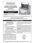
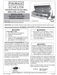
Since 1937 c ELITE 50 GOURMET UNIBODY SERIES 17 OUTDOOR GAS BARBECUE INSTALLATION AND OPERATING INSTRUCTIONS INSTALLER: Leave these instructions with consumer. CONSUMER: Retain for future reference. Photo shows Elite 50 Gourmet Slide-In with Hanger and Oven with Double Backburners. IMPORTANT: READ THESE INSTRUCTIONS CAREFULLY BEFORE STARTING INSTALLATION SAFETY WARNINGS & CODES 1. 2. 3. 4. FOR YOUR SAFETY FOR YOUR SAFETY IF YOU SMELL GAS: 1. Do not store or use gasoline or other flammable vapors and liquids in the vicinity of this or any other appliance. Shut off the gas to the appliance. Extinguish any open flame. Open lid. If odor continues, immediately call your gas supplier or Fire Department. AVERTISSEMENT S’IL Y UNE ODEUR DE GAZ : 1. 2. 3. 4. Coupez l’admission de gaz l’appareil. Éteindre toute flamme nue. Ouvrir le couvercle. Si l’odeur persiste, appeler immédiatement votre compagnie de gaz ou votre département des incendies. CODE AND SUPPLY REQUIREMENTS: This Barbecue must be installed in accordance with local codes and ordinances, or in the absence of local codes, with the latest National Fuel Gas Code, ANSI Z223.1. IN CANADA: The Barbecue must include the Canadian Certification mark and bilingual marking with bilingual instructions to comply with the Canadian Interprovincial Gas Advisory Council (IGAC) requirements. 2. A Propane cylinder not connected for use shall not be stored in the vicinity of this or any other appliance. AVERTISSEMENT 1. Ne pas entreposer ni utiliser de l’essence ni d’autres vapeurs ou liquides inflammables dans le voisinage do l’appareil, ni de tout autre appareil. 2. Une bouteille de propane qui n’est pas raccordée en vue de son utilisation, ne doit pas être entreposée dans le voisinage de cet appareil ou de tout autre appareil. WARNING: Improper installation, adjustment, alteration, service or maintenance can cause injury or property damage. Refer to this manual. For your safety, this Barbecue should be installed or inspected by a qualified installer, technician or the gas supplier. This appliance and its individual shutoff valves must be disconnected from the gas supply piping system when testing the system at pressures in excess of ½ psig. This appliance must be isolated from the gas supply piping system by closing its individual manual shutoff valves during any pressure testing of the gas supply system at pressures up to and including ½ psig. Rev 1 042804 Robert H. Peterson Co. • 14724 East Proctor Ave. • City of Industry, CA 91746 1 L-C2-07604 CONTENTS ELITE 50 SLIDE-IN SERIES 17-xxxxx-x e 141,000 BTU's with Backburners pl . m'D saQ sE es R l n ai O StOT Front to Back Depth 23-3/4" Width 51", Height 12", Open Front s rePH i u eq W RE ALSO AVAILABLE IN CABINET MODELS N CONTENTS Safety Warnings & Codes Pg. 1 Contents Pg. 2 Tools Required-Check List Pg. 3 Barbecue Parts List Pg. 3 Backburner & Oven Parts List Pg. 4 Planning for Installation of Your Barbecue Pg. 5 Gas Supply Requirements Pg. 5 Safe Use and Maintanence of Propane Gas Cylinders Pg. 6 Connecting Your Barbecue to The Gas Supply Pg. 7 Checking Your Barbecue Pg. 8 Adjusting Your Barbecue Pg. 9 Barbecue Lighting Instructions Pg. 10 Operating Your Barbecue Pg. 11 Features & Accessories Pg. 12 Barbecue Safety Information & Maintenance Pg. 13 Troubleshooting Pg. 13 Care & Cleaning Pg. 14 Cooking Times & Temps Pg. 15 Sample Recipes Pg. 15-16 Warranty Pg. 16 This manual may not be copied, photocopied, reproduced, translated, or published in any electronic or machine-readable form in whole or in part without prior written approval of Robert H. Peterson Co. For Technical Help call your local Fire Magic Dealer first 2 TOOLS REQUIRED- CHECK LIST SUPPLIED ITEM CHECK LIST TOOLS AND SUPPLIES REQUIRED FOR INSTALLATION •Elite 50 Barbecue: •Outer Flavor Grids (4) •Fire Magic Grilling Chips (1 can) •Sample Recipe Book (1) •Grill lifter (1) •Match holder (1) •Replacement Barbecue orifices (8) •Wood chip box (1)* •Backburner cover (2) * •Backburner Replacement Barbecue orifices (2)* *For Elite 50 with Backburners only: • #2 (medium) Phillips screwdriver • Two medium size adjustable wrenches • One pair of pliers • One flat blade screwdriver • * 3/8" wrench or 3/8" socket screwdriver • Pipe joint compound resistant to all gasses • C.S.A.Approved Stainless Steel Flex Connector ( See Page 4, paragraph 4-a.) *Note: 3/8" socket if orifice change is required. FIRE MAGIC ELITE 50 GOURMET UNIBODY GAS BARBECUE PARTS LIST Cooking Grids Stainless Steel Cast Iron Porcelain Cast Iron Part No. by Set (2 sets required) 3539-S-2 (22x12) 3527-4 (22x6) 3539-2 (22x12) 200070, Flavor Grid 3199-60, Electrode Assembly w/Wiring Burners Stainless Steel Cast Brass Porcelain Cast Iron Cast Iron Part No. (4 sets required, -2 per set) *3041-40-2 *3041-25-2 *3041-30-2 *3041-10-2 3030-01, Flex Tube Assembly (2) *3270-06, Burner Clips (8) 3199-36 Crossover Box (3) 3980-4105, Bolt 3981-0005, Washer (2) 3990-0010, Nut *3041-01, Air Shutter (8) *3048-03, Spring, Air Shutter (8) 3199-32, Ignitor Generator Spark Kit (4) *3000-12, Fastner Set 24185-00, Elite-50 Slide-In Unibody Burner Manifold Assembly (4) Natural Gas Propane Gas 3185-10 3185-10P 3000-65 Bezel w/Pad (6) 4185-10 Valve Manifold Assembly 24185-07, Elite-50 Face, Stainless 3012 Valve Knob (6) Note: Items marked * sold as two per package Match Holder 3083, Drip Tray Robert H. Peterson Co. • 14724 East Proctor Ave. • City of Industry, CA 91746 3 FIRE MAGIC ELITE 50 BACKBURNER & OVEN PARTS LIST EXPLODED VIEW OF BACKBURNER ASSEMBLY PARTS INCLUDED WITH THE BACKBURNER ASSEMBLY ARE INSIDE THE BROKEN LINES 4728-02 Right Backburner Assembly 4739-02 Left Backburner Assembly 4199-69 Electrode Double Rod w/Electrode Wire 3990-0037 3/4 Pal Nut EL-34 Elbow (Lid Stop) 4732-09 Woodchip Box 3001-125-1 Orifice, LP 3001-45-1 Orifice, Nat EMBE R USE IS IN RNER use. KBU in N BAC er is not ER WHE burn COV Back THIS r when OVE ace cove Repl REM REM IONN UTIO CAUT CA RE ER BEFO RE NER COV KBEFO ER BUR THISCOV NER OVE R BAC K BUR YOU THIS REM OVE TINGYOUR BAC REM LIGH TING LIGH EMBE R IS IN RNER use. KBU in N BAC er is not ER WHE burn COV Back THIS r when OVE ace cove Repl REM REM USE IONN UTIO CAUT CA RE ER BEFO RE NER COV KBEFO ER BUR THISCOV NER OVE R BAC K BUR YOU THIS REM OVE TINGYOUR BAC REM LIGH TING LIGH 3990-0025 Nut, 6-32 Hex SS 3984-4103 Screw, 10-32 x 3/8 SS Air Shutter & Adj. Screw 3986-1102 Screw, 6-32 x 1/4 SS 3030-01 Backburner Gas Line w/Compression Nuts & Sleeves 4728-010 Backburner Cover EXPLODED VIEW OF OVEN ASSEMBLY IMPORTANT Your Fire Magic Barbecue, Oven and Backburner are fully Pre-assembled and tested at the factory. DO NOT attempt to remove the oven and Backburner from the Barbecue prior to or during installation. Damage to the connecting gas line and ignitor wiring may occur. OVEN LOCK NUT The plastic straps which secure the oven to the Barbecue unit should be removed and discarded prior to lighting. EL-34, ELBOW & ORIFICE (LID STOP) IGNITOR ELECTRODE WIRE Robert H. Peterson Co. • 14724 East Proctor Ave. • City of Industry, CA 91746 4 PLANNING FOR INSTALLATION OF YOUR ELITE 50 GOURMET BARBECUE Fire Magic Barbecues are designed FOR OUTDOOR USE ONLY. WARNING: Built-in models must be installed in masonry or other type of fireproof enclosure. The unit is NOT insulated and therefore must be installed with 18" of side and back clearance from unprotected combustible materials such as wood, plastic, or stucco with wood framing. DO NOT install this unit under unprotected flammable surfaces. DO NOT install or use this appliance inside a building, garage, or any other enclosed area including recreational vehicles or boats. This is a SLIDE-IN TYPE unit designed to fit into open-front PROPANE CYLINDER ENCLOSURES enclosures. The Front Panel (Face) of the unit is removable for To prevent invisible combustible gas from accumulating in gas hookup, servicing and Burner adjustment, and MUST remain your cylinder enclosure, you must provide adequate ventilation. removable after you install the unit. This is accomplished by having one side of the enclosure left INSTALLER NOTE: This unit should be installed so that it can completely open to the outside OR by providing four (4) be removed at a later date if factory service is required. Any ventilation openings. Two openings are to be at the cylinder protrusion into the Barbecue enclosure may obstruct the frame valve level (Approx.16” above the floor) and on opposite walls and prevent the unit from sliding into place (see "Gas Supply of the enclosure. Two more openings must be at the floor level on opposite sides of the enclosure. The floor level Plumbing Requirements" below). openings must start at the floor and shall extend no higher ENSURING PROPER COMBUSTION AIR & COOLING FLOW than 5” above the floor. Each opening must have a minimum 2 Maintaining proper air flow for your Fire Magic Barbecue is of 10 square inches (64.5 cm ) of free area. To achieve the proper ventilation, you may drill a series of holes, omit the essential if it is to perform as it was designed (Fig 1). If airflow is blocked, overheating and poor combustion will result. Make grout from masonry joints or replace a brick with a hardware sure not to block the 1" front air inlet along bottom of Barbecue cloth screen. If the floor in the cabinet is raised and the Face. Note: The front air space allows access to Drip Tray. space beneath the cabinet is open to the outside, the lower ventilation openings may be in the floor. FOR YOUR SAFETY, you must provide these openings for drainage, replacement air and cross ventilation of any storage area exposed to possible leakage from gas connections, the Barbecue or Propane Cylinder. IMPORTANT: Additional requirements for safe use of Propane gas and gas cylinders appear on Pg. 6 of this manual. Figure 1 Ventilation Diagram HOUSEHOLD PROPANE GAS SERVICE Consult your gas supplier for ventilation requirements when connecting to a household Propane supply. When using Propane gas, take EXTREME CAUTION to ensure ELECTRICAL OUTLETS ample ventilation of gas vapor. Propane vapor is invisible and heavier than air. A DANGEROUS EXPLOSION could occur, All electrical outlets in area of Barbecue must be grounded. resulting in SERIOUS INJURY, OR LOSS OF LIFE if Propane Installer and User Note: Keep electrical supply cords away gas is allowed to accumulate and then ignite. from all heated surfaces. Only one Propane gas cylinder may be located in an EXHAUST REMOVAL enclosure. Extra or spare cylinders must be stored outdoors out of the reach of children and outside of any building, garage If installed under a patio roof, the grill area should be fully or other enclosed area. READ AND FOLLOW ALL WARNINGS covered by a chimney and exhaust hood. An exhaust fan with PROVIDED WITH PROPANE GAS CYLINDERS. Never a rating of 1000 CFM (cubic feet per minute) or more may be locate a cylinder under or near Barbecue unless sufficient necessary to efficiently remove smoke and other cooking byventilation and shielding is provided to prevent any heating of products from the covered area. Installation in fully-enclosed patio areas is not recommended. cylinder, regulator and rubber hose. VENTILATION OF ENCLOSURES GAS SUPPLY REQUIREMENTS GAS SUPPLY PLUMBING REQUIREMENTS Figure 2 - Gas Stub Diagram CONNECT TO GAS LINE STUB IN THIS AREA Rigid 3/4" or 1” black steel pipe, or local code approved pipe for temperatures up to 800°F (427°C), is required to conduct gas supply into enclosure opening for connection to the unit. Do not use a rubber hose within enclosure for Barbecue unit. Apply only joint compounds that are resistant to all gasses on all male pipe fittings. Make sure to tighten every joint securely. 23 3/4" DEPTH 3 NOTE: Review page 7, prior to connecting unit. If 1/2” Pipe is used, it should be no longer than five feet and only to conduct Gas Supply into Barbecue cut out for connection to the Flex Connector. The gas supply pipe should enter through the floor at rear of enclosure and terminate near the left end (Figure 2). 2 7 1 12" HEIGHT 12 51" WIDTH SAFETY NOTE: An external valve (with a removable key) in the gas line is necessary for safety when your Barbecue is not in use. It also provides for convenient maintenance Install gas line stub at least 2" away from the left side and back walls, but within 9" of the back wall and 14” from the left wall, as illustrated by the shaded area in Figure 2. No Pipe or fittings should rise higher than 2 1/2” into the bottom of the Barbecue. 5 SAFE USE & MAINTENANCE OF PROPANE GAS CYLINDERS READ AND FOLLOW ALL WARNINGS PROVIDED WITH YOUR PROPANE GAS CYLINDER. IMPORTANT FOR YOUR SAFETY When operating this appliance with a Propane gas Cylinder these instructions and warnings MUST be observed. FAILURE TO DO SO MAY RESULT IN A SERIOUS FIRE OR EXPLOSION. CYLINDER AND CONNECTOR REQUIREMENTS AND SPECIFICATIONS QUICK COUPLER OPERATION To connect the Regulator/hose assembly to the LP gas a. Propane gas cylinders and valves must be maintained in cylinder valve fitting: Press the Hand Nut on the Regulator good condition and must be relaced if there is visible damage over the Acme thread fitting on the cylinder valve. Turn the to either the cylinder or valve. Hand Nut clockwise to engage the threads and tighten until snug. The use of pliers or wrench should not be necessary. b. This Barbecue, when used with a cylinder, should be connected to a standard 5 gallon (20lb.) Propane gas cylinder To disconnect:- Turn the Hand Nut counter-clockwise until equipped with an OPD (Overfill Prevention Device). The OPD detached. (Figure 3a). has been required on all cylinders sold since October 1,1998 Important: Before using the Barbecue and after each time the to prevent overfilling. cylinder is removed and reattached, check all connections for c. Cylinder dimensions should be approximately 12 inches in leaks. Turn off the Barbecue valves and open the main cylinder diameter and 18 inches high. Cylinders must be constructed valve, then check connections with soapy water. Repair any and marked in accordance with the specifications for Propane leaks before lighting the Barbecue. Gas Cylinders of the U.S. Department of Transportation (D.O.T) CAUTION: Always turn the Propane cylinder main valve off or the National Standard of Canada,CAN/ CSA-B339, Cylinders, after each use and before moving the Barbecue and cylinder or Spheres and Tubes for Transportation of Dangerous Goods. disconnecting the coupling. This valve must remain closed d. The cylinder must include a collar to protect the cylinder while the appliance is not in use, even though the gas flow is valve and the cylinder supply system must be arranged for stopped by a safety feature when the coupler is disconnected. vapor withdrawal. Carefully inspect the hose assembly each time before the gas e. The pressure regulator and hose assembly (Figure 3A,) is turned on. A cracked or frayed hose should be replaced supplied with this outdoor cooking gas appliance must be used. immediately. Original and replacement pressure regulator and hose If the appliance is stored indoors, the cylinder must be assemblies must be those specified by the Robert H. Peterson disconnected and removed. Cylinders must be stored out of Co. for connection with a cylinder connecting device identified the reach of children and must not be stored in a building, as Type I by the Harmonized Standard ANSI Z 21.58 and CGA garage or any other enclosed area. 1.6-M95-1995 with Addenda ANSI Z 21.58a -1998 and CGA 1.6a - M98. FOR YOUR SAFETY f. The Propane gas cylinder valve must be equipped with a a. DO NOT store a spare Propane Gas cylinder under cylinder connection coupling device, described as Type I in or near this appliance. the Harmonized ANSI standard defined in paragraph e. above. This device is commonly described as an Acme Thread Quick b. NEVER fill the cylinder beyond 80 percent full. Coupler. c. IF THE INFORMATION IN “A” AND “B” IS NOT g. Your Propane Gas Cylinder may be equipped with a Type II FOLLOWED EXACTLY, A FIRE CAUSING DEATH OR Quick Disconnect (plug-in) Coupler (Figure 3B). An approved SERIOUS INJURY MAY OCCUR. regulator /hose assembly for this type of coupling is available through your dealer from R.H. Peterson Co. QCC TYPE I CYLINDER VALVE (QUICK DISCONNECT COUPLER) TYPE II CYLINDER VALVE (QUICK DISCONNECT COUPLER) MAIN VALVE HANDWHEEL BRASS COUPLING NUT PRESSURE RELIEF VALVE HANDWHEEL BRASS COUPLING SLEEVE REGULATOR UL VENT PRESSURE RELIEF VALVE REGULATOR UL NIPPLE CYLINDER LIQUID LEVEL INDICATOR (OPTIONAL) VENT HAND NUT WITH ACME THREAD HOSE CYLINDER LIQUID LEVEL INDICATOR (OPTIONAL) HOSE Figure 3A Type I Acme Thread Quick Coupler Figure 3B Type II Quick Disconnect Coupler GAS SUPPLY AND MANIFOLD PRESSURES: For Natural Gas For Propane Gas Normal 7" Water Column (w.c), Normal 11" Water Column (w.c.) Minimum 31/2" w.c. , Maximum 101/2" w.c. Minimum 8" w.c., Maximum 13" w.c. For useful advice and help with constructing your barbecue contact your local Fire Magic dealer 6 CONNECTING YOUR ELITE 50 GOURMET BARBECUE TO THE GAS SUPPLY TO CONNECT TO THE GAS SUPPLY IF THE OVEN IS SEPARATED FROM THE BARBECUE, IT WILL REQUIRE TWO PEOPLE TO INSTALL IT. a. The Elite Barbecue is supplied with an approved stainless steel flex connector to bring the gas supply from the gas line stub to the Valve Manifold. A 7/8”x 36” Connector is provided with a 1/2" female pipe adapter on one end to connect to your gas suply. a. Make sure the Backburner gas supply tubes are protruding above the side panels of the barbecue frame (Figure 4). The Backburner electrode wires should be positioned outside of the Barbecue for the Oven to sit correctly. b. Carefully place the oven on the frame so the Backburner gas supply tubes fit into lid stop elbows on the oven (Figure 6). The front lip of the oven may sit on the face of the Barbecue. CAUTION: Use only stainless steel flex connectors that are C.S.A. listed. WARNING: A rubber or plastic connector will rupture or leak, resulting in an explosion or serious injury if used inside the Barbecue enclosure. c. Hand tighten the compression nuts onto the lid stopelbows d. Use a wrench and turn the elbow (lid stop) to push the oven to the back of the Barbecue frame (Figure 5). b. Make sure that your gas supply is turned off! Then connect the 1/2" pipe adapter fitting supplied with the stainless steel flex connector to the gas supply stub. Use pipe joint compound that is resistant to all gasses on the male pipe fitting and tighten securely. DO NOT use pipe joint compound to connect the Flare Fittings. e. Tighten the compression nuts on the Backburner gas supply tubes to the elbow lid stops. Do not use pipe joint compound on these connections. f. Place the right Backburner electrode wire through the oven just in front of the elbow (lid stop). Secure with nut and screw. c. Slide your Barbecue into place, making sure not to pinch or Plug the electrode wire into the Backburner electrode (see Parts kink the gas connector. List diagram on page 3). Make sure the electrode wire does not d. Bring the flex connector around the left-hand side of the touch the Backburner. Repeat above instructions for left Barbecue. Use the Locator Angle Brackets on the left lower- Backburner electrode wire. frame to position the flex connector. Continue the flex connector g. Make sure the Barbecue Burner valves are in the "OFF" along the left side to the front of the unit and the Valve Manifold position. Turn the gas supply ‘ON’. Carefully check all gas Inlet. Be careful not to block the 1" Front Vent opening as this connections for leaks with a brush and soapy water before will obstruct Drip Tray removal. lighting. NEVER USE A MATCH OR OPEN FLAME TO TEST FOR LEAKS. e. Connect the flex connector to the Flare Fitting on the Manifold Inlet. Support the Manifold Inlet Fitting with a wrench to avoid applying excessive torque to the Manifold Assembly while tightening this connection securely. DO NOT use pipe compound on Flare Fittings. h. Refer to the "Air Shutter Adjustment” instructions below, the Backburner “Air Shutter Adjustment” instructions on page 9 and "Lighting instructions" on the back page of this manual before replacing the Barbecue face and knobs. IF THE OVEN IS FITTED CONTINUE WITH (f and g) BELOW. IF IT IS SEPERATED GO TO NEXT SECTION. f. Make sure the Barbecue Burner valves are in the "OFF" position. Turn the gas supply on. Then carefully check all gas connections for leaks with a brush and soapy water before lighting. NEVER USE A MATCH OR OPEN FLAME TO TEST FOR LEAKS. g. Refer to the "Air Shutter Adjustment Instructions" and "Lighting instructions" in this manual before replacing Barbecue face and knobs. Figure 4 Figure 5 BACKBURNER ELECTRODE WIRE 7 CHECKING YOUR BARBECUE BARBECUE FUEL ORIFICE SIZE 3. CHECK BACKBURNER FUEL ORIFICE SIZE Elite 50 Gourmet Unibody Barbecues are equipped with fuel orifices for Natural gas, unless otherwise indicated. To use with Propane gas, you must install smaller orifices to avoid hazardous overheating. If your Barbecue includes a Backburner it is equipped with a Natural Gas orifice unless otherwise indicated. To use Propane Gas, you must use a smaller orifice. The proper orifice for Natural Gas is #45 (drill size). The proper orifice for Propane Gas is #125 (1.25mm). For Elite 50 Barbecues: The proper orifice size for Natural Gas is #48 (drill size). The proper orifice size for Propane Gas Hazardous overheating will occur if a Natural Gas orifice is used with Propane Gas. If you are not sure, or if an orifice is #57 (drill size). change is necessary, refer to the instructions included with the IF YOU ARE NOT SURE YOU HAVE THE CORRECT replacement orifice which is packed with the Barbecue. BARBECUE BURNER ORIFICE SIZE IF YOU ARE NOT SURE YOU HAVE THE CORRECT a. Remove the Cooking Grids and Flavor Grids from the BACKBURNER ORIFICE SIZE Barbecue. b. If the gas supply has been connected, make sure the Burner 1. Remove the Backburner assembly (Figure 7). Valves are in the “Off” position. Then pull the Valve knobs from a. Remove the Backburner cover if in place. their stems. Use a Phillips screwdriver to turn the Face Fastener b. Unplug the Ignitor wire from the electrode. Screws counter clockwise to release the Face and remove it c. Remove the mounting screw from the mounting bracket from the Barbecue. Retain the screws and finish washers for at the left end of the Backburner assembly. Be careful not reattaching the Face. to lose the 3/8" spacer (if equipped) when screw is removed. d. Carefully pull the left end of the backburner assembly NOTE: Carefully lift the face away from the frame. The Spark forward, keeping it against the left side of the oven, until Generator for the ignition system is attached to the inside of the right end of the burner clears the orifice. the face panel. The Spark generator Knob need not be detached, but the wires must be unplugged from the generator 2. Check the size stamped on the orifice. 3. If an orifice change is necessary, use a 3/8" hex nutdriver before the face is removed. or appropriate wrench or pliers to replace the orifice. c. Using a flat blade screwdriver, pry the burner retaining clip 4. Replace the Backburner assembly, following step a. through from rear wall of the barbecue frame (see Figure 6). Remove d. above, in reverse order. the burner by; A) Pulling it to the front of the barbecue, B) Lift 5. Re-check the air shutter instructions. the far end out of the notch, C) Pull the burner away from the manifold, taking care not to lose air shutter and spring, which may become detached when the Burner is removed. OVEN LEFT SIDE d. Using a 3/8" socket, remove orifice from the orifice holder on the burner manifold and check the number stamped on the face (see "Barbecue Orifice Size" above). Repeat for each burner as necessary. MOUNTING BRACKET ELECTRODE e. If your barbecue is not orificed for the gas supply you plan to use, replace them with the orifices supplied with the barbecue or orifices supplied by your local dealer. AIR SHUTTER ORIFICE MOUNTING SCREW f. After checking orifice drill size or replacing the orifice, install the Air Shutter Spring and the Air Shutter over the orifice holder fitting, between the Burner and the Burner Manifold, in the order and position shown in Figure 6. IGNITOR WIRE Figure 7 g. Replace the burners in the holding groove, ensuring that the brass orifice and orifice holder fittings project deeply into the Burners. Replace the burner retaining clips. Figure 6 - Burner Orifice Diagram BURNER BURNER NECK SPRING AIR SHUTTER BURNER CLIP CHECKING THE BARBECUE REGULATOR The Barbecue Regulator, located behind the Front Panel (Face), must be set for the type of gas used to fuel the Barbecue. To check the regulator setting remove the cap in the center of the regulator (Fig 8A). Holding the cap vertical (see Fig 8B), the letters at bottom of the plastic stalk should indicate the gas type that the reguator is currently set up for. If regulator is not set for your gas type, remove stalk from cap, invert and replace into center of cap. Replace cap on regulator, screwing down until snug. 8 BURNER MANIFOLD WITH ORIFICE HOLDER ORIFICE BARBECUE REGULATOR. NOTE THE CAP ON TOP READ GAS TYPE HERE Figure 8A Figure 8B ADJUSTING YOUR ELITE 50 GOURMET BARBECUE REATTACHING THE FACE & IGNITOR WIRES ADJUSTING YOUR BARBECUE IMPORTANT: This appliance may not light or heat evenly Pull the Drip Tray out far enough to or cook properly unless the Air Shutters are adjusted support the Face in the vertical following installation (See "Air Shutter Adjustment" below). position. Lean the Face forward and plug the 2 wires into the terminals AIR SHUTTER ADJUSTMENT on the Spark Generator (Figure 11). The Air Shutters are located at the front of the Burners behind The wires can be plugged into either the Face and Heat Shield (see Parts List)Burner Air Shutters terminal. Figure 11 - Spark and are easily accessed by removing the Front Panel (Face) IMPORTANT: Test the Electrodes Generator and Heat Shield. Close the air shutters by turning the tabs to a for spark before securing the Face to vertical position. (Figure 9). Light your Barbecue in accordance the frame (see Page 12 for Battery Replacement). Place the with the lighting instructions (page 6) and burn for 2 minutes Face on the Frame so the Front Lip of the Face covers the lip with the valves on high and the oven open. on the frame. After burning for 2 minutes, open the Air Shutters until the ADJUSTING THE FLAME HEIGHT flames lift off, or appear not to be touching the Burners. Then begin closing the Air Shutters until the flames appear to burn The large knobs on the Face of the Barbecue control the Valves while touching the Burner Ports (Figure 9). You may then see and adjust flame height. The first position is “High,” the second short yellow tips on the flames. If flames are a lazy yellow, “Medium” and the final “Low.” Flame height can also be set open the Air Shutters until the flame is blue with yellow tipping. anywhere between the High, Medium and Low settings for all cooking requirements and methods. NOTE: Barbecues in some installations achieve a better air/ gas mixture and will ignite more quickly if the valve is first Height of the flame with the valve in low position may be regulated by means of a small adjusting screw in the center of turned beyond High to Medium or Low for lighting. the valve stem. This screw is accessible by removing the plastic valve knob which pulls straight off the end of the valve stem. TAB DIMPLE PARTIALLY OPEN NOTCH FLAME OFF PORTS 5. INSTALL THE FLAVOR GRIDS Place the Flavor Grid directly on the Burners centering the Grids over the Burners with the open side up (Fig 12). This allows heat from the Burners to be evenly distributed throughout the cooking area. Fire Magic Flavor Grids are Stainless Steel and will heat and cool quickly, making your Barbecue very responsive to the changes you specify in grill temperature. They are rust resistant and may be cleaned with standard oven cleaners. (TURN TABS) FLAME ON PORTS CLOSED Figure 9- Air Shutter Adjustment Diagram IMPORTANT: It is normal for the Backburner to smoke when it is burned for the first time. Burning your Backburner on high for approximately 15 minutes will eliminate the smoking. FLAVOR GRIDS BACKBURNER AIR SHUTTER ADJUSTMENT FLAVOR GRID LEG a. The Air Shutter on your Backburner is preset at the factory. However, due to atmospheric conditions and different gas pressures, it may be necessary to adjust the Air Shutter to obtain a proper burn. BURNER b. First remove the Backburner cover, then loosen the Air Shutter screw (See Fig. 10). It may be necessary to use pliers to turn the Air Shutter. Light the Backburner. With the control knob on "HIGH" adjust the Air Shutter to have a blue flame that is not lifting off the Burner (It may also have slightly yellow tips). c. Tighten the Air Shutter adjustment screw. Figure 12 - Flavor Grid Diagram AIR SHUTTER SCREW Figure 10 9 LIGHTING INSTRUCTIONS Read entire instructions before lighting. Follow the instructions each time you light your Fire Magic Barbecue or Backburner. FOR MANUAL LIGHTING: FOR AUTOMATIC LIGHTING: CAUTION: Always wait 5 minutes for gas to clear after any unsuccessful lighting attempt. 1. Open the lid. 2. Turn all three Barbecue gas valves and the Backburner valve to the “OFF” position. 1. Follow steps 1 through 4 of "Automatic Lighting" section 3. Turn on the gas at the source outside of the Barbecue enclosure. 2. Insert either a burning long-barrel butane lighter, a burning long-stem match or a burning match held by the match holder (attached to the drip tray) (Figure 9) through the TO Figure 9 - Match Holder F PU TUSH RN TO OF TU RN RN TU ON TO OFF HI LIGHT 4. Remove the Backburner cover if you are lighting the Backburner. OFF MARKER HIGH TO Cooking Grids to the Burners below the Flavor Grid (Figure 10). For Backburners, hold the flame against the perforated material near the Backburner. LIGHT NOTE: DO NOT turn on more than one valve at a time for either Figure 8 - Valve Control Knob automatic or manual lighting. Adjacent Barbecue Burners will cross-ignite. ME D 5. Depress either the center gas valve knob or the Backburner knob and turn to “HIGH” then immediately press the Spark Generator button (see Figure 10). The Burners should light. CAUTION: If the Burners do not light within 5 seconds depress the knob and turn the valve to “OFF”. WAIT 5 MINUTES before repeating step 5 If the Burners still do not light after several attempts, refer to the instructions for manual lighting. 3. While holding the match or lighter flame next to the Burner, depress the appropriate Valve knob and turn it counterclockwise to the “HIGH” position. The Burner should light. 4. If Burner does not light, IMMEDIATELY DEPRESS the knob and turn valve to “OFF”. WAIT 5 MINUTES before repeating steps 2 through 4 of Manual lighting instructions. NOTE: Barbecues in some installations achieve a better air/ gas mixture and will ignite quicker if the valve is first turned beyond High to Medium or Low for lighting. IF YOU SMELL GAS 1. Shut off gas to the appliance. 2. Extinguish any open flame. 3. Open lid. 4. If the odor continues, immediately call your gas supplier or fire department. REMEMBER: FOR SAFE MANUAL LIGHTING, PLACE A BURNING MATCH OR BUTANE LIGHTER BESIDE THE BURNER - THEN TURN ON THE GAS (Figure 10). 10 Backburner Valve Figure 10 - Knob Positions & Manual Lighting Backburner Ignitor Button OPERATNG YOUR BARBECUE To extend the life of your Fire Magic Barbecue, follow these Smoker Tray (Woodchip Box) steps prior to cooking: Your Backburner is supplied with a woodchip box. The 1. Begin by heating the unit at a normal cooking temperature woodchip box is designed to sit on top of the Backburner for several minutes. assembly over the notch in the heat deflector (See Fig. 13). 2. Then open the Control Valves to the “High” setting to burn This box is designed to be used when the Backburner is in use. To use the box, just fill it with your favorite woodchips and set off residue remaining from prior use. it in place. If you wish to refill the woodchip box when it is hot, 3. When the Barbecue has heated sufficiently, set heat to the you may carefully handle it using a pair of pliers. You must be desired cooking level. very cautious not to get burned. 4. When using a smoke oven, closing the cover during the The Backburner Cover preheat period will accelerate the preparation process. DO NOT a. The Backburner cover is installed by placing the curved part operate unattended at High Flame as cooking temperatures of the cover over the top of the perforated portion of the will quickly be exceeded. Backburner (See Fig. 13). Using Your Optional Backburner b. The cover should be kept in place on the Backburner when Rotisserie cooking with the Backburner is accomplished without it is not in use. This will keep your Backburner free from grease use of the main grill Burners. The cooking grids are removed splatter and debris that may hinder its performance. and if large cuts are to be barbecued, the Flavor grids may be removed to allow more clearance from the spit rod to the fire WARNING: You must remove the Backburner cover before box. Aluminum Foil or a baking pan may be placed over the lighting the Backburner. main Burners to catch excess drippings from your cooking. FLAVOR FROM WOOD CHIPS OR CHARCOAL a. Remove the Backburner cover. (Fig.13) Convenient Fire Magic Gourmet Grilling Chips* are sold in b. Place your meat on the rotisserie spit rod. Make sure it is several different popular wood types. These chips are precentered on the spit. Refer to the instructions provided with moistened and sealed in cans, a sample of which is provided with your barbecue. To use follow the instructions on the side your Fire Magic Rotisserie and counter balance. of the can. After use there is no mess to clean up, just discard the can of ashes after there is no longer any wood smoke c. Follow the lighting instructions on page10 aroma. More Fire Magic Gourmet Grilling Chips* may be d. Allow the Backburner to preheat for approximately 10 purchased through your local dealer. minutes on "HIGH" setting. You may also add wood chips, wood chunks or the natural e. Place the spit rod with the meat into the rotisserie and turn wood charcoal of your choice to the Flavor Grid. We recommend placing wood outside the direct cooking zone or wrapping it in on the motor. perforated aluminum foil. Soaking wood before use will slow f. Use a standard roasting guide to estimate the length of time burning and increase smoke flavor. Wood and charcoal ash for your meat. A meat thermometer may also be used to tell will remain in the Flavor Grid after use. The Grid can be easily when your favorite cuts are cooked to your liking. When testing removed and cleaned when unit has fully cooled. temperatures with a thermometer, turn off the rotisserie motor and turn the Backburner on "Low". This will keep the meat from over cooking on one side g. Operate your Backburner with the oven closed. This will simulate an oven effect and help your meat cook faster. The constant rotation of the spit assures even cooking and maximum retention of juices. h. On large cuts of meat or whole turkeys, it may be necessary to reduce the heat from your Backburner. Cooking your food at lower temperature for a longer period will keep the outer surface from burning, while cooking the interior of your food thoroughly. ` WOODCHIP BOX BACKBURNER COVER BACKBURNER AIR SHUTTER SCREW POSITION Figure 13 *Available from your nearest Fire Magic Dealer 11 FEATURES AND ACCESSORIES Installing and using Your Optional Rotisserie Kit 4 COUNTER BALANCE MOTOR THUMB SCREW 5 HANDLE 2 SPIT ROD 6 1 SPIT BRACKET 3 SPIT PRONGS BARBECUE RIGHT SLOT BARBECUE LEFT SLOT BARBECUE FRONT FACE Item No.Part No. 1. 2. 3. 4. 5. 6. 3600-05 3600-18 3613 3600-13 3607-40 3620 Description To use the Counterbalance supplied with your Barbecue: Elite fan cooled motor Spit bracket with offset Elite spit prongs Handle Spit rod 5/8" hex x 51 1/2" Counter Balance 1. Place meat on the spit in the normal manner. Center and balance as carefully as possible. 1. Remove the cooking grids from your barbecue. 2. Tighten the screws on the prongs, chicken holder or turkey holder to secure the meat. 3. Hold spit rod at each end and lift. Do not grip the rod. Let rod rotate so heavy side of meat hangs down naturally. 2. Place the rotisserie motor with the bracket into the slot on 4. Turn the counterbalance on the spit so the counterbalance rod and weight point upward or opposite from the heavy side the right side of your barbecue, making sure the knob and of the meat. Tighten the counterbalance rod in the hub cord are facing away from the barbecue (see above). against a flat surface of the spit rod to secure. 3. Place the spit bracket into the slot on the left side of your 5. Loosen the thumb screw and slide the weight along the barbecue with the offset out. counterbalance rod to balance the meat. Since meats are 4. Place pointed end of the spit rod into the motor. The groove not a uniform shape, it may not be possible to achieve a in the handle end of the spit will rest on the spit bracket . perfect balance. Properly balanced meat should not rotate when you hold the spit rod loosely by the ends. Note: The Counter Balance, which is included with your Rotisserie Kit, should be used to balance the load on your rotisserie and prolong the life of your motor. Heavy unbalanced 6. Make sure the counterbalance does not strike the barbecue frame when the rotisserie is started. meats can stress rotisserie motor and may cause failure. REPLACING THE SPARK GENERATOR BATTERY USING THE COOKING GRILL LIFTER Hold the Grill Lifter by gripping the center section with the NOTE: DO NOT ATTEMPT TO prongs pointing down (Using oven mitt or heavy glove if the TURN THE PLASTIC BEZEL grill is hot). Insert the notched end of the Grill Lifter into the RING. DOING THIS MAY BREAK grill, in front of the midway point (front to back- Figure 14A) THE BEZEL RING AND DAMAGE and central (left to right-Fig 14B). Twist the grill lifter (clockwise THE IGNITOR. or counter-clockwise) so the handle is parallel to the grill rods. WRONG! This “seats” the spiked end of the Grill Lifter between two rods 1. Remove the rubber cap by depressing and turning the cap enabling you to safely lift the grill out of the barbecue. Lift counterclockwise and lifting away the cap. slowly and adjust the Grill Lifter if necessary to balance. 2. The battery is now accessible for removal and replacement. Make sure that the battery spring is re-installed with the new battery, and the battery is negative (-) end up. Figure 14A Placement of the Grill Lifter in Grill Figure 14B WARMING RACK Your Fire Magic warming rack is packed seperately with the barbecue. It is assembled quickly and easily following the instructions provided. When complete, just position it as suggested to enjoy the benefits this useful accessory affords. 3. Replace rubber cap by pressing in and turning it clockwise. until it locks into place. 12 BARBECUE SAFETY INFORMATION & MAINTENANCE 5. The Drip Collector hole is clear and unobstructed. Excessive grease deposits can result in a grease fire. Each time you use your Barbecue, make sure that: 1. The area around the Barbecue is clear of flammable 6. The in-line gas valve or gas cylinder valve is always shut substances such as gasoline, yard debris, wood, etc. off when the Barbecue is not in use. 2. There is no blockage of the air flow through the vent space DRIP COLLECTION SYSTEM located below the Face of the unit. The Drip Collector in this Fire Magic Barbecue is part of the unit’s main frame, and is located below the Burners. The Drip a. The special ventilation openings in the enclosure Collector has one hole which allows excess drippings to fall are kept free and clear of debris. through during cooking while separating the firebox from the b. If connected to a Propane cylinder, the rubber hose drip tray. attached to the Regulator is carefully inspected before The Drip Collector allows you to brush or scrape residue from each use. the Barbecue inner liner into the Drip Tray. Regular cleaning of your Barbecue interior with oven cleaner or Fire Magic c. The Propane cylinder, Regulator and rubber hose are installed in a location not subject to heating above Foaming Barbecue & Grill Cleaner*, following manufacturers instructions, will prevent grease fires. 125° F (51° C). 3. When using Propane gas: 4. The Burner flames burn evenly along both sides of each Burner with a steady flame (mostly blue with yellow tipping). See “Air Shutter Adjustment” below. If Burner flames are not normal, check the orifice and Burner for insects or insect nests (see Pg.4, Sect. 2, for Burner removal and replacement). WARNING: NEVER cover the entire cooking or grill surface with griddles or pans. Overheating will occur and Burners will not perform properly when combustion heat is trapped below the cooking surface. CAUTION: NEVER spray water on a hot gas unit as this may damage porcelain or cast iron components. *Available from your nearest Fire Magic Dealer PROBLEMS & TROUBLESHOOTING If you have trouble with your Fire Magic Barbecue, please use this list to identify the problem. By trying one or more of the solutions to a possible cause you should be able to solve the problem. If this list does not cover your present problem or you have other difficulties with the barbecue, please contact your local dealer or visit our website at www.rhpeterson.com PROBLEM POSSIBLE CAUSE CORRECTION 1) Adjust air shutters (see Page 9) 1) Improper air shutter adjustment. Ignition System Failure 2) Re-plug wires into Spark generator (see Page 9) 2) Ignition wire disconnected 3) Check regulator setting (Page 8) and have Gas Co. check operating pressure at the barbecue 3) Low gas pressure 4) Dead Battery Insufficient Heat 4) Replace Battery 5) Improper air shutter adjustment 5) Adjust air shutters (see Page 9) 6) Using Propane orifice for Natural Gas 6) Change orifices (see Page 8) 7) Low Gas Pressure 7) Have Gas Company check the operating pressure at the barbecue 8) Burner ports partially blocked by debris Uneven heating Rotisserie Noisy 8) Remove burners (see Page 8) Clean out ports 9) Small spiders or insects in burner 9) Inspect burners for spider webs or other debris that may block gas flow 10) Rotisserie out of balance 10) Adjust Rotisserie counterbalance 13 CARE OF YOUR FIRE MAGIC BARBECUE CARE OF STAINLESS STEEL COMPONENTS COOKING GRIDS Your Barbecue may have a stainless steel oven and front panel. The following care instructions will keep your unit looking and working like new. Stainless steel components are constructed of the finest prime grade type 304 stainless steel. Meticulous attention has been given to maintain the attractive finish throughout the manufacturing process. Like the stainless steel used in commercial kitchens, your Barbecue requires regular cleaning and occasional buffing to maintain its bright, clean appearance. Fire Magic Cooking Grids come in two types: Stainless Steel and Porcelain-Finished Cast-Iron Grids. Both are finished with a special matte (satin) finish. This matte-finish provides a more stick-resistant cooking surface that makes outdoor barbecuing easy and enjoyable. The Stainless Steel Cooking Grids are made of type 304 stainless steel, and the coating on the Porcelain-Finished Grids provides a cooking surface that resists corrosion and increases cooking grid durability, providing years of cooking enjoyment. For best cooking performance, the wide side of the grid bars should face up. Follow the simple steps of Care and Maintenance after every use. WIPE WITH GRAIN CARE AND MAINTENANCE (Stainless Steel Grids) To maintain your Stainless Steel Cooking Grids, we recommend lightly brushing the grids after use with a brass or stainless steel wire brush. Before use, brush again if necessary and spray a light coat of vegetable oil over the cooking surface. Discoloration or stubborn food particles can be removed with a heavy-duty abrasive or stainless steel scouring pad. Grills can also be washed in an automatic dishwasher or cleaned with strong cleaning solutions, including oven cleansers. We do not recommend ordinary steel or wire brushes, which may leave tiny metal particles on the grids which cause discoloration, but not permanent damage. Figure 15 - Always rub with the grain (Porcelain Coated) Deposits of dirt and grease can be removed easily with Fire Magic Foaming Barbecue and Grill Cleaner*. Deposits should be removed before they are allowed to bake onto the finish. To remove more stubborn deposits, use a scouring pad recommended for stainless steel. Be sure to always rub in the direction of the polishing lines (Figure 15). Oven cleaner may be used, according to manufacture's instructions, to remove cooked-on food deposits. Special cleaning agents and polishing pads recommended for stainless steel are available at your local Barbecue dealer, hardware store or supermarket. A spray coat of vegetable oil and light brushing with a brass grid brush before and after use is all it takes to maintain cooking readiness and ensure long life. PROTECTING THE WHOLE BARBECUE FINISH Barbecue covers* will protect the finish and extend the life and appearance of Fire Magic Barbecues equipped with smoke ovens. The covers are designed to protect the finish against scratches, corrosion and oxidation. Each cover has been cut and sewn by hand to fit a particular smoke oven model. Flaps CAUTION: Never use ordinary steel wool or steel brushes on extend from the sides and back. In windy areas, place weights stainless steel. Tiny particles left behind may rust and stain the on the flaps or inside the sleeve on the flaps to keep the cover finish. Abrasive pads recommended for restoring the grain in from blowing off. stainless steel will, over a period of time, scratch or dull the surface of glass or porcelain-coated products. BURNER MAINTENANCE Fire Magic Burners are constructed of heavy-duty cast stainless steel and have a lifetime warranty (cast brass and porcelainized cast iron Burners are also available). Once a year inspect the Burners to insure that the ports are clear of debris. REPLACING THE SPARK GENERATOR BATTERY 1. Remove the rubber cap by depressing and turning the cap counterclockwise. 2. The battery is now accessible for removal and replacement. 3. Make sure that the battery spring is re-installed with the new battery. *Available from your nearest Fire Magic Dealer *Accessories and replacement parts may be obtained from your nearest Fire Magic Dealer. Figure 16 - Cover for Built-in Barbecue For assistance in locating a dealer, please contact our factory at the address listed below. Visit our Website at www.rhpeterson.com to view our full range of Fire Magic and Real-Fyre products and accessories. Robert H. Peterson Co. • 14724 East Proctor Ave. • • City of Industry, CA 91746 • 14 COOKING TIMES &TEMPERATURES Once your barbecue is installed, tested and working, the moment you have been working towards and waiting for; cooking a gourmet meal for your family and friends on your new Fire Magic Barbecue has arrived. In order to get you off to a wonderful start, we have included with your barbecue a few sample recipes. These mouthwatering recipes are taken from our new barbecue cookbook, “Great Gourmet Grilling” written by Chef Steven Fohl. We heartily recommend you try these recipes and if you enjoy them as much as we think you will, you may wish to purchase the complete book with over 60 recipes (including salads and desserts. It also contains many useful tips and hints so you can get the best out of your Fire Magic Barbecue, while taking a journey into a new world of taste and cooking. To order this book, just complete the Order Form at the inside the last page of the booklet. Also, to help you get the best from your barbecue, we list below some typical cooking times and temperatures, again taken from Chef Fohl's Recipe book. Typical Cooking Times and Internal (Meat) Temperatures Rare Medium Well Done 5-7 min. 16-18 min. 12-14 min. 16-20 min. 1400F 7-9 min. 18-20 min. 14-17 min. 20-25 min. 1600F 9-11 min. 22-24 min. 16-20 min. 25-28 min. 1700F Lamb 1" thick Chops 7-10 min. Roast* 20-25 min. (Temp.) 1400F 10-13 min. 25-30 min. 1500F 15-18 min. 30-35 min. 1800F Beef 1" Steaks 2" Steaks 1" Burgers Roast* (Temp.) Pork 1" thick Chops Spare Ribs 25-30 min. 45-60 min. Roast Fresh Pork* Well Done Fish Fillets, Steaks Whole Fish Poultry (Temp.) Chicken (small pieces) (large pieces) Whole birds Chicken Duck Turkey (not stuffed) (stuffed) 25-30 min. (1700F) 10-15 min. (1400F) Smoked Ham* Sausages (fresh) (fully cooked) 10-14 min. per pound 10-12 min. per inch thick 1850F 35-60 min. 45-60 min. 60-75 min. 16-20 min. per pound 11-13 min. per pound 13-15 min. per pound BON APPETIT! 25-30 min. 12-16 min. (*denotes per pound) BARBECUE RECIPES MEDITTERANEAN PORK AND SIRLOIN BURGERS Serves: 10 Prep time: 30 minutes Cook time: 15 minutes 3lbs 3lbs 1/2 1/2 1/4 1/4 1 11/2 1 11/2 1/4 2 2 1 1. 2. 3. 4. ground Sirloin ground pork cup chopped garlic cup finely chopped scallions cup parsley cup basil tablespoon cracked pepper tablespoons oregano ~ dry teaspoon chili flakes tablespoon dry basil cup water cups Jarlsburg or quality Swiss cheese, coarsley shredded tablesppons olive oil tablespoon salt Mix above ingredients well. Hand form oval burgers, weighing just about 8oz. each. Grill burgers slowly over medium low heat. serve with thick sliced tomatoes, basil leaves, Romaine lettuce, red onions, and splash of balsamic vinegar NEW YORK CUT SIRLOIN STEAKS Prep time: 15 minutes Cook time: 20 minutes 10 oz. sirloin strip steaks - New York cut Salt & pepper Oil 1. Salt and pepper steaks evenly & completely - both sides. 2. Brush or rub lightly with oil. 3. Allow to stand 5 - 10 minutes. 4. Place on hot grill and mark 2 - 4 minutes. 5. Flip and mark 2 - 4 minutes. 6. Lightly season again and brush with oil or butter. 7. Flip and cook 3 - 4 minutes. 8. Lightly season again and brush with oil or butter. 9. Flip and cook 3 - 4 minutes. • On third or fourth turn, you may want to mark a check or diamond pattern. • By searing both sides of steak, and then cooking, this method will ensure evenly cooked meat. • Allowing grilled meats to rest for 2 - 5 minutes after cooking will redistribute juices creating a more tender, juicy and evenly cooked steak. • Never press or pierce meat during cooking - a well done steak CAN be juicy & tender. 15 BARBECUE RECIPES (cont'd) LEMON ZEST & PARSLEY MARINATED TURKEY STEAKS served with Homemade Cranberry Sauce SUMMER GRILLED MARINATED VEGETABLES Serves: 10 Prep time: 1 hour + marinating time Cook time: 15 minutes Serves: 10 Prep time: 1 hour + marinating time Cook time: 20 minutes Turkey Steak 6 lbs. boneless turkey breast 1 tablespoon minced garlic 1/2 cup lemon juice 2 tablespoons lemon zest 4 tablespoons parsley - freshly chopped 1/2 teaspoon thyme - fresh 1 teaspoon sugar 1/2 cup olive oil VEGETABLES 2-4 zucchinis ~ slice 1/2" lengthwise 2-4 crookneck squash ~ slice 1/2" lengthwise 3 red bell peppers ~ cut top & bottom ~ cut side faces 2-4 tomatoes ~ firm and meaty type, slice 1/2" 2-4 eggplants ~ slice 1/2" 1 onion or scallion 1lb greenbeans ~ whole ~ trim stem end only Portobello mushrooms ~ whole caps 1. Cut turkey in 8 oz. steaks cut crosswise and pound slightly. 2. Distribute remaining ingredients over and under steaks. 3. Cover and marinate overnight. 4. Grill for approximately 5 minutes per side. 5. Serve with cranberry sauce. MARINADE (Evenly marinate vegetables for up to 24 hours) CRANBERRY SAUCE 5 cups cranberries - fresh or frozen 11/2 -2 cups sugar - adjust tartness to your liking 1 cup apricot jelly 1 cup orange juice 1. Combine all ingredients in a heavy gauge sauce pot. 2. Bring to a gentle boil for 10 - 20 minutes. 3. Adjust sweetness or tartness with sugar. 4. Remove from heat. Serve warm or cold. May store covered for up to 4 weeks in refrigerator. 1/2 11/2 1/4 1 1/4 2 1 1 1/4 1/4 11/2 cup white wine cups lemon juice cup minced garlic cup parsley ~ freshly chopped cup basil ~ freshly chopped tablespoons oregano ~ dry teaspoon chili flakes tablespoon black pepper cup salt cup sugar cups oil Grill vegetables for 20 minutes on medium heat. Chef's Note: Other vegetable options - Carrots, Belgian endive, baby artichokes, fennel, savoy cabbage, leeks. FIRE MAGIC OUTDOOR GAS BARBECUES LIMITED WARRANTY PLEASE COMPLETE AND RETURN YOUR REGISTRATION CARD WHICH IS INCLUDED WITH YOUR BARBECUE LIFETIME WARRANTY - Fire Magic Cast Stainless Steel Burners, Stainless Steel Rod Cooking Grids and Stainless Steel Housings (including liners, frames, ovens and barbecues faces) are warranted for as long as you own your Fire Magic Barbecue. FIFTEEN YEAR WARRANTY - Fire Magic Cast Brass Burners, Brass Valves, Backburner Assemblies (except ignition parts), Manifold assemblies and Porcelain Housings (including liners, frames, ovens and barbecues faces) are warranted for 15 years from the date of purchase of your Fire Magic Barbecue. THREE YEAR WARRANTY - Fire Magic Sideburners and all other Fire Magic Barbecue components (except ignition parts) are warranted for 3 years from the date of purchase of your Fire Magic Barbecue. Fire Magic ignition systems and barbecues accessories are warranted for one year from date of purchase. PLEASE KEEP A COPY OF YOUR SALES SLIP FOR PROOF OF PURCHASE This warranty applies to the original purchaser with invoice or proof of purchase and covers Fire Magic products intended for personal, family or household usage only. It does not apply to rust, corrosion, oxidation or discoloration, which may occur due to moisture or overheating, unless the affected component becomes inoperable. This waranty does not cover parts becoming defective by misuse, accidental damage, improper handling and/or installation. It does not cover labor or labor related charges. It specifically excludes liability for indirect, incidental or consequential damages. Some states do not allow the exclusion or limitation of incidental or consequential damages, so the above exclusion may not apply to you. This warranty gives you specified legal rights and you may have other rights which may vary from state to state. For additional information regarding this warranty, or infromation on how to place a warranty claim, contact your authorized Fire Magic dealer Visit our Website at www.rhpeterson.com to view our full range of Fire Magic, Real-Fyre and Hallmark products and accessories. Accessories and replacement parts may be obtained from your nearest Fire Magic Dealer. For assistance in locating a dealer, please contact our factory at the address listed below. Robert H. Peterson Co. • 14724 East Proctor Ave. • City of Industry, CA 91746 16