1
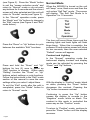
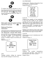
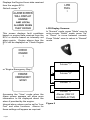
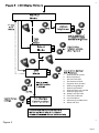
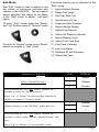
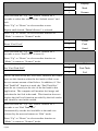
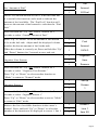
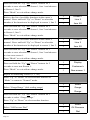
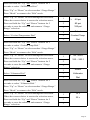
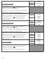
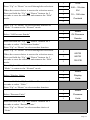
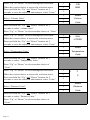
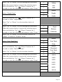
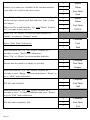
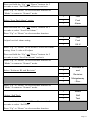
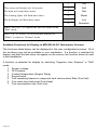
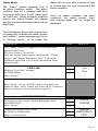
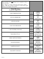
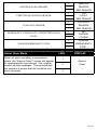
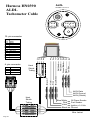
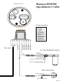
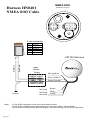
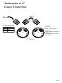
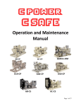
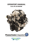
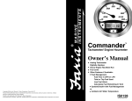
Owner’s Manual
GM ALDL MG2000™
Tachometer
IS0195
rev. A ecr#5576 8/2005
IS0195 x7 w/ corrections
Mark ups 12/20/05
Index
Figure 1 Default screens
Description
Normal Mode
Contrast and Lighting
Displayed Functions
Default screen 1
Default screen 2
Default screen 3
Default screen 4
Figure 2 Screen Sequence
Figure 3 LCD Display Screens
Edit Mode
Functions that are adjusted in Edit Mode.
Select Default Screen
Reset Fuel Used
Set Fuel Tank Full
Set Amount of Fuel
Organize User Screens
Select Gauge Range
Select Oil Pressure Dial
Select Coolant Temp Dial
Select Voltmeter
Select Water Press Dial
Select Boost Press Dial
Select Fuel Sender
Select Oil Pressure Sender
Select Display Units
Select Pressure Units
Select Volume Units
Select Temperature Units
Select Distance Units
Select Depth Units
Select Fuel Tank Size
Select Other Fuel Tank Size
Fuel Tank Calibration
Low Fuel Alarm
Software ID and Revision
Select Self Test
Alarm Mode
Low Fuel
Engine Warnings
Alarm Messages From ECU
Alarm Clear Mode
Harness HN0390
Harness HN0401 GPS NMEA0183 Cable
Harness Two inch Gauge connection
page 1
page 1
page 2
page 2
page 3
page 3
page 3
page 3
page 4
page 4
page 5
page 7
page 7
page 7
page 8
page 8
page 9
page 9
page 10
page 10
page 11
page 11
page 12
page 12
page 12
page 13
page 13
page 13
page 14
page 14
page 14
page 15
page 15
page 15
page 16
page 17
page 17
page 17
page 19
page 19
page 19
page 20
page 21
page 22/23
page 24
page 25
This page left blank intentionally.
The FARIA MG2000 Tachometer
combines the features of an ECU serial
bus gateway and several instruments
into one unit:
• The tachometer is analog in
appearance but driven by a stepper
motor for digital accuracy.
• The high resolution LCD screen
displays information for many other
functions and the various “screens”
can be configured as the user
wishes. As received, the screens
are configured as shown in Fig. 1.
The MG2000 receives digital engine data
from the Engine Control Unit (ECU) via
the GM ALDL bus and can receive GPS
information via a NMEA 0183 connection
to a suitable GPS unit. GPS information
is displayed in the MG2000 speedometer.
Analog inputs are provided for two nonengine sensors such as fuel level and oil
pressure.
The MG2000 provides a Faria Bus output
to allow use of various other 5, 4, and 2
inch instruments with the MG2000.
The Faria MG2000 Tachometer will turn
on when the ignition key is turned on and
will turn off when the ignition key is turned
off. The unit will power up showing the
default screen selected by the user.
Figure 1
The instrument has three push buttons;
“M” “Mode”, “Down”, and “Up”; that
control the functions available. The “M”
“Mode” button is used to change the
function of the LCD display and to access
submenus and adjustable settings. The
“Down” and “Up” buttons are used to
modify the settings.
Default Screens
In the “Normal” operation mode, pressing
the “Mode” button and then pressing
“Down” or “Up” button causes the display
to cycle between the available screens
Page 1
(see Figure 2). Press the “Mode” button
to exit the “screen selection mode” and
return to “Normal” mode or do not push
any buttons for 4 seconds and the current
screen will stay selected and the unit will
return to “Normal” mode (see Figure 3).
In the “Normal” operation mode, press
the “Mode” and “Up” buttons to change to
the “Edit” menus (see Figure 3 and “Edit”
mode below).
Press the “Down” or “Up” buttons to cycle
between the available “Edit” functions.
Normal Mode
When the MG2000 is turned on the unit
will “beep” once, flash once and then the
unit enters “Self Test” mode. The screen
will display “The Self Test Mode Is In
Operation” for 10 seconds.
The horn will sound three times and the
warning lights and back lights will flash
three times. When this is complete, the
software ID and revision screen will show
for two seconds, then the user selected
“Default” screen will appear.
Contrast and Lighting
Press and hold the “Down” and “Up”
buttons for two (2) secs to select an
“Edit” function to change. Within each
“Editing” function the “Down” or “Up”
buttons select settings or sub-functions.
Follow the instructions in the “Edit” mode
section of this manual to save the new
settings after you select / adjust them.
To exit the “Edit” mode after the edit is
completed, press the “Mode” button to
return to “Normal” mode.
In the “Normal“ operating mode the
instrument display contrast and display
mode can be adjusted by pressing the
“Down” and “Up” buttons.
With the display in “Positive” mode, black
on white, pressing the “Down” button
decreases the contrast. Pressing the
“Up” button increases contrast.
Continuing to press the “Up” button
causes the display to reverse to the
“Negative” mode, white on black. The
contrast in this mode is controlled the
same way as the “Positive” mode.
To return to “Positive” mode, continue to
press the “Down” button until the display
reverses.
Page 2
OIL PRESSURE
Analog input. Displays information from
the analog oil pressure sender.
Default Screen “2”
To adjust the lighting intensity of all of
the instruments in the system, press and
hold both the “Down” and “Up” buttons
for 2 seconds. The lighting intensity may
now be adjusted by using the “Down” or
“Up” buttons.
Fuel Left
Return to the “Normal” mode by pressing
and holding both the “Down” and “Up”
buttons for 2 seconds.
Displayed Functions
Tachometer
The tachometer is a digital instrument with
the appearance of an analog instrument.
The tachometer receives data directly
from the ECU so no settings are required
for the dial range. A microprocessor
controlled stepper motor moves the
pointer to display engine revolutions per
minute.
Default Screen “1”
Displays the quantity of fuel remaining
in the fuel tank based on the original
quantity of fuel in the tank when full and
the amount of fuel used based on the
GPH from the engine ECU and the time
spent at each GPH. Fuel tank size and
reset are available in the “Edit” mode.
Fuel Used
Displays the amount of fuel used since
reset based on the GPH from the engine
ECU and the time spent at each GPH.
Fuel Inst
Displays the current, instantaneous, fuel
flow in GPH.
Default Screen “3”
Engine Temp
Volts
Displays system voltage as received
from the ECU (Engine Control Unit).
Displays the coolant temperature
received from the ECU. Dial range can
be selected in the “Edit” function.
Engine Hours
Page 3
Displays the Engine Hours data received
from the engine ECU.
Default screen “4”
LCD Display Screens:
This screen displays fault conditions
based on engine data received from the
ECU or alarms based on internally set
alarm points. Engine alarms from the
ECU will be displayed as “Check Engine
!”
In “Normal” mode, press “Mode” once to
enter screen “Select” mode, press “Up”
or “Down” to move between screens.
Press “Mode” once to return to “Normal”
mode.
Screen “1”
or “Engine Emergency Stop !”.
Screen “2”
Screen “3”
Screen “4”
Alarms (ONLY IF
ALARMS ACTIVE)
Accessing the “View“ mode when the
Alarm screen appears will allow more
information to be displayed about the
alarm if provided by the engine.
Internal alarm values can be set for “Low
Fuel” and other functions. Alarms for
these settings will appear as required.
Page 4
Figure 2
40
1.
2.
3.
4.
5.
6.
7.
8.
9.
10.
11.
12.
13.
14.
Select Default Screen
Reset Fuel Used
Set Fuel Tank Full
Set Amount of Fuel
Organize User Screens
Select Gauge Range
Select Fuel Sender
Select Oil Pressure Sender
Select Display Units
Select Fuel Tank Size
Fuel Tank Calibrate
Low Fuel Alarm
Software ID and Revision
Select Self Test
Figure 3
Page 5
This page left blank intentionally.
Page 6
Edit Mode
The “Edit” mode is used to adjust or set
the values of numerous functions and
options in the MG2000. The procedure
below specifies the steps to be taken
in the “Edit” mode to adjust / set each
option.
To enter “Edit” mode, press the “Mode”
and “Up” buttons while in “Normal” mode
Functions that are set or adjusted in the
“Edit” mode:
1. Select Default Screen
2. Reset Fuel Used
3. Set Fuel Tank Full
4. Set Amount of Fuel
5. Organize User Screens
6. Select Gauge Range
7. Select Fuel Sender
8. Select Oil Pressure Sender
9. Select Display Units
10. Select Fuel Tank Size
To return to “Normal” mode, press “Mode”
button once while in “Edit” mode.
11. Fuel Tank Calibrate
12. Low Fuel Alarm
13. Software ID and Revision
14. Select Self Test
Instructions – Function
Select “Default Screen.”
LINE
DISPLAY
1
Select
2
Default
3
Screen
1
Display
2
Screen
3
1
Press and hold the “Up” and “Down” buttons for 2
seconds to select the “Default Screen.”
Press “Up” or “Down” to select another function or
“Mode” to return to “Normal” mode.
(Display Screen 1 is the “Default” at first turn on.)
Press and hold the “Up” and “Down” buttons for 2
seconds to select screen 1 as the “Default Screen” and
exit.
Press “Up” or “Down” to select another screen.
Page 7
1
Display
2
Next
3
Screen
1
Reset
2
Fuel
3
Used
1
Set
2
Fuel Tank
3
Full
Press and hold the “Up” and “Down” buttons for 2
seconds to select this screen as the “default screen” and
exit.
Press “Up” or “Down” to select another screen.
Repeat until desired “Default Screen” is selected.
Press “Up” or “Down” to select another function or
“Mode” to return to “Normal” mode.
Reset “Fuel Used”
Press and hold the “Up” and “Down” buttons for 2
seconds to reset “Fuel Used” to zero (0).
Press “Up” or “Down” to select another function or
“Mode” to return to “Normal” mode.
Set “Fuel Tank Full”
NOTE: In order to use the “Fuel Left” function, the owner
must set this function when the fuel tank is filled or use
the set current amount of fuel below. In addition, if “Set
Fuel Tank Full” function is used, the “Fuel Tank Size”
must be set correctly to the size of the fuel tank in this
application. The computer will monitor fuel usage and
calculate the fuel left in the tank. This function does not
replace the fuel level function provided by the fuel sender
and should be used with caution.
Press and hold the “Up” and “Down” buttons for 2
seconds to set “Fuel Tank Full.”
Automatically sets the fuel available to the tank size
selected by the user and returns to “Edit” mode.
Press “Up” or “Down” to select another function or
“Mode” to return to “Normal” mode.
Page 8
Set “Amount of Fuel”
1
Set
2
Amount
3
Of Fuel
NOTE: If a known amount of fuel is in the fuel tank but
it is not full, this function can be used to indicate the
amount of fuel available. The “Fuel Left” function will
then use the amount of fuel entered to calculate the “Fuel
Left.”
Press and hold the “Up” and “Down” buttons for 2
seconds to select “Current Amount of Fuel.”
Press “Up” or “Down” to set the amount of fuel known
to be in the fuel tank. Adjust until the displayed volume
matches the known amount of fuel in the tank.
1
When the volume is correctly set, Press and hold the “Up”
and “Down” buttons for 2 seconds to save and exit.
3
XXX G
1
Organize
2
User
3
Screens
1
Set up
2
Screen
3
1
1
Screen 1
2
Line 1
3
Item XX
Organize User Screens
2
Fuel
Amount
Press and hold the “Up” and “Down” buttons for 2
seconds to select “Organize User Screens.”
Press “Up” or “Down” to select another function or
“Mode” to return to “Normal” mode.
Organize Screen 1
Press and hold the “Up” and “Down” buttons for 2
seconds to select “Organize Screen 1.”
Press “Up” or “Down” to select another screen or “Mode”
to return to “Edit” mode.
Refer to the list of available functions in the ownerʼs
manual. Press and hold “Up” or “Down” to select the
number of the function to be displayed in screen 1, line 1.
Page 9
Press and hold the “Up” and “Down” buttons for 2
seconds to save selection for Screen 1, line 1 and advance
to Screen 1, line 2.
Press “Mode” to exit with no change made.
Refer to the list of available functions in the ownerʼs
manual. Press and hold “Up” or “Down” to select the
number of the function to be displayed in screen 1, line 2.
1
Screen 1
2
Line 2
3
Item XX
1
Screen 1
2
Line 3
3
Item XX
1
Display
2
Customer’s
3
New screen 1
1
Select
2
Gauge
3
Range
1
Select
2
Oil Pressure
3
Dial
Press and hold the “Up” and “Down” buttons for 2
seconds to save selection for Screen 1, line 2 and advance
to Screen 1, line 3.
Press “Mode” to exit with no change made.
Refer to the list of available functions in the ownerʼs
manual. Press and hold “Up” or “Down” to select the
number of the function to be displayed in screen 1, line 3.
Press and hold the “Up” and “Down” buttons for 2
seconds to save selection for Screen 1, line 3 and advance
to view new screen 1.
Press “Mode” to exit with no change made.
Press and hold the “Up” and “Down” buttons for 2
seconds to save new Screen 1.
Press “Mode” to exit with no change made.
Repeat for remaining screens (2, 3, etc).
Press “Up” or “Down” to select another function or
“Mode” to return to “Normal” mode.
Select “Gauge Range” (dial reading range)
Press and hold the “Up” and “Down” buttons for 2
seconds to select “Gauge Range.”
Press “Up” or “Down” to select another function.
Select “Oil Pressure Dial”
Page 10
Press and hold the “Up” and “Down” buttons for 2
seconds to select “Oil Pressure Dial.”
Press “Up” or “Down” to select another “Gauge Range.”
Press “Mode” to return to the “Edit” mode.
Press “Up” or “Down” to scroll through the selections.
When the correct choice is next to the selection arrow,
Press and hold the “Up” and “Down” buttons for 2
seconds to save the selection and return to “Gauge
Range” selection
Select “Coolant Temperature Dial”
1
>
2
60 psi
80 psi
100 psi
3
1
Select
2
Coolant Temp
3
Dial
Press and hold the “Up” and “Down” buttons for 2
seconds to select “Coolant Temp Dial.”
Press “Up” or “Down” to select another “Gauge Range.”
Press “Mode” to return to the “Edit” mode.
Press “Up” or “Down” to scroll through the selections.
When the correct choice is next to the selection arrow,
Press and hold the “Up” and “Down” buttons for 2
seconds to save the selection and return to “Gauge
Range” selection.
Select “Voltmeter Dial”
1
>
60 –220 f
100 – 250 f
2
3
1
Select
2
Voltmeter
3
Dial
Press and hold the “Up” and “Down” buttons for 2
seconds to select “Voltmeter Dial.”
Press “Up” or “Down” to select another “Gauge Range.”
Press “Mode” to return to the “Edit” mode.
Press “Up” or “Down” to scroll through the selections.
When the correct choice is next to the selection arrow,
Press and hold the “Up” and “Down” buttons for 2
seconds to save the selection and return to “Gauge
Range” selection.
1
2
>
16 v
32 v
3
Page 11
Select “Water Press Dial”
1
Select
2
Water Press
3
Dial
Press and hold the “Up” and “Down” buttons for 2
seconds to select “Water Press Dial.”
Press “Up” or “Down” to select another “Gauge Range.”
Press “Mode” to return to the “Edit” mode.
Press “Up” or “Down” to scroll through the selections.
When the correct choice is next to the selection arrow,
Press and hold the “Up” and “Down” buttons for 2
seconds to save the selection and return to “Gauge
Range” selection.
Select “Boost Press Dial”
1
2
>
30 PSI
45 PSI
3
60 PSI
1
Select
2
Boost Press
3
Dial
1
20 PSI
2
> 30 PSI
3
50 PSI
4
70 PSI
1
Select
2
Fuel
3
Sender
Press and hold the “Up” and “Down” buttons for 2
seconds to select “Boost Press Dial.”
Press “Up” or “Down” to select another “Gauge Range.”
Press “Mode” to return to the “Edit” mode.
Press “Up” or “Down” to scroll through the selections.
When the correct choice is next to the selection arrow,
Press and hold the “Up” and “Down” buttons for 2
seconds to save the selection and return to “Gauge
Range” selection.
Select “Fuel Sender”
Press and hold the “Up” and “Down” buttons for 2
seconds to select “Fuel Sender.”
Press “Up” or “Down” to select another function.
Page 12
1
>
USA
Press “Up” or “Down” to scroll through the selections.
2
240 – 33 ohm
When the correct choice is next to the selection arrow,
Press and hold the “Up” and “Down” buttons for 2
seconds to save the selection and return to the “Edit”
mode.
3
EU
4
10 – 180 ohm
5
Centroid
6
Press “Up” or “Down” to select another function or
“Mode” to return to the “Normal” mode.
Select “Oil Pressure Sender”
1
Select
2
Oil Pressure
3
Sender
Press and hold the “Up” and “Down” buttons for 2
seconds to select “Oil Pressure Sender.”
Press “Up” or “Down” to select another function.
Press “Up” or “Down” to scroll through the selections.
When the correct choice is next to the selection arrow,
Press and hold the “Up” and “Down” buttons for 2
seconds to save the selection and return to the “Edit”
mode.
1
2
3
60 PSI
80 PSI
100 PSI
Press “Up” or “Down” to select another function or
“Mode” to return to the “Normal” mode.
Select “Display Units”
1
Select
2
Display
3
Units
1
Select
2
Pressure
3
Units
Press and hold the “Up” and “Down” buttons for 2
seconds to select “Units.”
Press “Up” or “Down” to select another function.
Select “Pressure Units”
Press and hold the “Up” and “Down” buttons for 2
seconds to select “Pressure Units.”
Press “Up” or “Down” to select another choice of
“Units.”
Page 13
Press “Up” or “Down” to scroll through the selections.
1
When the correct choice is next to the selection arrow,
Press and hold the “Up” and “Down” buttons for 2
seconds to save the selection and return to select “Units.”
2
Select “Volume Units”
>
PSI
BAR
3
1
Select
2
Volume
3
Units
Press and hold the “Up” and “Down” buttons for 2
seconds to select “volume units”
Press “Up” or “Down” to select another choice of “Units”
Press “Up” or “Down” to scroll through the selections.
1
When the correct choice is next to the selection arrow,
Press and hold the “Up” and “Down” buttons for 2
seconds to save the selection and return to select “Units”
2
Select “Temperature Units”
>
GAL
LITERS
3
1
Select
2
Temperature
3
Units
Press and hold the “Up” and “Down” buttons for 2
seconds to select “Temperature Units.”
Press “Up” or “Down” to select another choice of
“Units.”
Press “Up” or “Down” to scroll through the selections.
1
When the correct choice is next to the selection arrow,
Press and hold the “Up” and “Down” buttons for 2
seconds to save the selection and return to select “Units.”
2
Select “Distance Units”
Press and hold the “Up” and “Down” buttons for 2
seconds to select “Distance Units.”
Press “Up” or “Down” to select another choice of
“Units.”
Page 14
>
F
C
3
1
Select
2
Distance
3
Units
Press “Up” or “Down” to scroll through the selections.
1
When the correct choice is next to the selection arrow,
Press and hold the “Up” and “Down” buttons for 2
seconds to save the selection and return to select “Units.”
2
kM
3
NM
1
Select
2
Depth
3
Units
Select “Depth Units”
>
Miles
Press and hold the “Up” and “Down” buttons for 2
seconds to select “Depth Units”
Press “Up” or “Down” to select another choice of
“Units.”
Press “Up” or “Down” to scroll through the selections.
1
When the correct choice is next to the selection arrow,
Press and hold the “Up” and “Down” buttons for 2
seconds to save the selection and return to select “Units.”
2
Meters
3
Fathoms
1
Select
2
Fuel Tank
3
Size
>
Feet
Press “Up” or “Down” to select another function or
“Mode” to return to “Normal” mode.
Select “Fuel Tank Size”
Press and hold the “Up” and “Down” buttons for 2
seconds to select “Fuel Tank Size”
Press “Up” or “Down” to select another function
Press “Up” or “Down” to scroll through the selections.
When the correct choice is next to the selection arrow,
Press and hold the “Up” and “Down” buttons for 2
seconds to save the selection and return to select “Units”
1
Select
2
Standard
3
Fuel Tank
4
Size
1
>
25 G
2
36 G
3
40 G
50 G
55 G
80 G
120 G
Page 15
If there is no tank size available in the list that matches
your tank size, scroll to the next screen.
Press “Up” or “Down” to set the fuel tank size displayed
on the screen to match your fuel tank size. Line 4 value
will adjust.
When set, Press and hold the “Up” and “Down” buttons
for 2 seconds to save and exit.
1
Select
2
Other
3
Fuel Tank
4
Size
1
Select
2
Other
3
Fuel Tank
4
XXX G
1
Calibrate
2
Fuel
3
Tank
1
Calibrate
2
Fuel Tank
3
Empty
1
Calibrate
2
Fuel Tank
3
Half
1
Calibrate
2
Fuel Tank
3
Full
Press “Up” or “Down” to select another function or
“Mode” to return to “Normal” mode.
Select “Fuel Tank Calibration”
Press and hold the “Up” and “Down” buttons for 2
seconds to select “Fuel Tank Calibration.”
Press “Up” or “Down” to select another function.
Ensure that fuel tank is as empty as possible.
Press and hold the “Up” and “Down” buttons for 2
seconds to save “Empty” calibration and press “Down” to
go to “Half” tank calibration.
Fill fuel tank half full.
Press and hold the “Up” and “Down” buttons for 2
seconds to save “1/2 tank” calibration and press “Down”
to go to “Full” tank calibration.
Fill fuel tank completely full.
Page 16
Press and hold the “Up” and “Down” buttons for 2
seconds to save “Full Tank” calibration and exit.
Press “Up” or “Down” to select another function or
“Mode” to return to “Normal” mode.
Select “Low Fuel Alarm” setting
1
Low
2
Fuel
3
Alarm
1
Low
2
Fuel
3
XX.X
1
Software Id
2
and
3
Revision
4
Minigateway
5
- Rev -
1
Select
2
Self
3
Test
Press and hold the “Up” and “Down” buttons for 2
seconds to select “Low Fuel Alarm.”
Press “Up” or “Down” to select another function.
Adjust low fuel alarm setting.
Press “Up” or “Down” to set desired “Low Fuel Alarm”
setting. Line 3 value will adjust.
Press and hold the “Up” and “Down” buttons for 2
seconds to save “Low Fuel Alarm” and exit.
Press “Up” or “Down” to select another function or
“Mode” to return to “Normal” mode.
Select “Software ID and Revision”
Press “Up” or “Down” to select another function or
“Mode” to return to “Normal” mode.
Select “Self Test”
Press and hold the “Up” and “Down” buttons for 2
seconds to select “Self Test.”
Press “Up” or “Down” to select another function.
Page 17
1
The
This screen will display for 10 seconds.
2
Self
The horn will sound three times.
3
Test
The warning lights will flash three times.
4
Mode
The backlights will flash three times.
5
Is in
6
Operation
When “Self Test” is complete the unit will return to the
“Edit” mode.
Press “Up” or “Down” to select another function or
“Mode” to return to “Normal” mode.
Available Functions for Display in MG2000 ALDL Tachometer Screens
The functions listed below can be displayed in the user configurable screens. All of
the functions may not be available in your installation. If a function is selected for
display and that function does not appear on the screen, the function does not exist
in this installation.
A function is selected for display by selecting “Organize User Screens” in “Edit”
mode.
1.
2.
3.
4.
5.
6.
7.
Page 18
System voltage
Oil Pressure
Coolant temperature (Engine Temp)
Engine hours
Fuel remaining based on usage and tank volume when filled (Fuel Left)
Fuel used since last reset (Fuel Used)
Fuel consumption rate (Fuel Inst)
Alarm Mode
The “Alarm” screen appears only if
an alarm condition exists. The alarm
condition may be a warning sent from
the engine ECU or a “Local” alarm such
as “Low Fuel”. When an alarm condition
occurs, the “Alarm Screen” will appear
and the screens described below will be
displayed.
alarm will re-occur after a period of time
to ensure that the user remembers the
alarm condition.
Once an alarm condition has been
corrected, the alarm screen, horn,
and warning lights will no longer be
displayed.
The descriptions below also explain how
to temporarily override the alarm screen
and audible / visual warnings and return
to “Normal” mode. In all cases, the
Alarm Mode
LINE
DISPLAY
The “Alarm” screen will appear if a local alarm or an
engine alarm occurs.
The local alarm is “Low Fuel”.
Only two engine alarms appear automatically, “Check
Engine” and “Engine Emergency Stop”. Follow the
instructions provided to view more information about
engine alarms.
LOW FUEL
Displays “Low Fuel” warning.
Red LED blinks.
Horn “Beeps”.
1
2
Low
Fuel
3
!
1
2
3
1
2
3
CHECK
ENGINE
!
Press “Mode” to turn off LED, silence alarm horn, and
return to “Run” mode. Alarm will reactivate in 15 minutes
but can continue to be deactivated as required.
ENGINE WARNINGS
Any engine alarm except “Engine Emergency Stop”
Red LED blinks.
Horn “Beeps.”
“Engine Emergency Stop” alarm.
Red LED on continuously.
Horn on continuously.
ENGINE
EMERGENCY
STOP !
Page 19
Press and hold “Up” and “Down” for 2 seconds to view
alarm messages.
Press “Mode” to silence alarm horn and return to “Run”
mode. LED will continue to function as stated until engine
alarm(s) is no longer sent by ECU.
Alarm Messages
From the Engine ECU
OVER TEMPERATURE
LOW OIL PRESSURE
LOW OIL LEVEL
LOW FUEL PRESSURE
LOW SYSTEM VOLTAGE
RPM REDUCTION
RPM LIMIT EXCEEDED
KNOCK SENSOR
IGNITION FAULT
MAGNETIC SENSOR
Page 20
1
2
3
1
2
3
1
2
3
1
2
3
1
2
3
1
2
3
1
2
3
1
2
3
1
2
3
1
2
3
HIGH
ENGINE
TEMP
LOW
OIL
PRESSURE
LOW
OIL
LEVEL
LOW
FUEL
PRESSURE
LOW
SYSTEM
VOLTAGE
RPM
REDUCTION
SEE DEALER
RPM
LIMIT
EXCEEDED
KNOCK
SENSOR
SEE DEALER
IGNITION
FAULT
SEE DEALER
MAG
SENSOR
SEE DEALER
1
2
3
1
2
3
1
2
3
1
2
3
1
2
3
MANIFOLD AIR SENSOR
THROTTLE POSITION SENSOR
COOLANT SENSOR
ENGINE ECU CABLE NOT CONNECTED OR NO
DATA
ENGINE EMERGENCY STOP
Alarm Clear Mode
When an alarm condition is corrected or
clears, the “Alarms Clear !” screen will appear
for approximately one second. The original
screen will then reappear. This ensures that
the operator is aware that the condition has
been corrected.
LINE
1
2
3
MAN AIR
SENSOR
SEE DEALER
TPS
FAULT
SEE DEALER
COOLANT
SENSOR
SEE DEALER
NO
ENGINE
FOUND
ENGINE
EMERGENCY
STOP !
DISPLAY
Alarms
Clear
!
Page 21
ALDL
Harness HN0390
ALDL
Tachometer Cable
MG2000 Tachometer
4
5
6
1
2
3
4
5
6
3
2
1
12
11
10
9
8
7
12- pin connector
Red
White
Green
Black
Violet
Pink
Blue/ White
Not Used
Not Used
Green/ Black
Black
Tan/ Blue
4- pin connector
Red
White
Green
Black & Sheild
Heat
Shrink
Tubing
Black
Pin A
Pin B
Pin C
Pin D
5 6 7 8 9 10 11 12
Not Used
Not Used
Green/ Black
Black
Tan/ Blue
12 3 4
Heat
Shrink
Tubing
Violet
Pink
Blue/White
Pin 1
Pin 2
Pin 3
Pin 4
Pin 5
Pin 6
Pin 7
Pin 8
Pin 9
Pin 10
Pin 11
Pin 12
ALDL Data
ALDL Ground
ALDL (Shield)
Blue/White
Pink
Violet
Black
Oil Press Sender
Fuel Sender
Ignition +14 Vdc
Ground
Wire Jacket
Page 22
Harness HN0390
Speedometer Cable
MG2000 Speedometer
4
5
6
1
2
3
4
5
6
3
2
1
12
11
10
9
8
7
12- pin connector
Pin 1
Pin 2
Pin 3
Pin 4
Pin 5
Pin 6
Pin 7
Pin 8
Pin 9
Pin 10
Pin 11
Pin 12
Red
White
Green
Black
Not Used
Tan/ Black
Tan
Not Used
Not Used
Not Used
Not Used
Not Used
Not Used
Not Used
Not Used
Not Used
Not Used
Air Temp/ Paddlewheel sender
Red (+V)
Tan
Tan/Black
Wire Jacket
Not Used
1 2 3 4 5 6 7 8 9 10 11 12
Green (Signal)
Bare (Ground)
Not Used
Not Used
White (Thermister)
Brown (Thermister)
Water Temp Sender
FARIA
White (Sender Signal)
Black & Shield (Ground)
Page 23
NMEA 2000
Harness HN0401
NMEA 0183 Cable
MG2000 Tachometer
4
5
6
11
10
9
8
7
1
12
2
3
6
3
2
5
1
4
6- pin connector
Pin 1
Pin 2
Pin 3
Pin 4
Pin 5
Pin 6
Not Used
Not Used
Red/ White
Red/ Blue
Not Used
Not Used
GPS100 Antenna
Red/ White
Red/ Blue
4 3
Heat
Shrink
Tubing
NMEA 0183-A
Red (Ignition)
Green (0183-A)
Shield (Ground)
NMEA 0183-B
Not Used
Ground
*Note:
Page 24
Not Used
Not Used
Brown*
White*
Yellow*
1) Cut off the connector at the end of the antenna cable
2) Cut off the following wires because they are not used: White, Yellow, Brown
3) Cut wires so that they are different lengths. This ensures they do not touch each other.
Tachometer to 2”
Gauge Connection
From
Tachometer
HN0503
4- pin connector
Pin A
Pin B
Pin C
Pin D
PJ0018
Red
White
Green
Black & Sheild
Note: To help reduce
moisture
in the gauges, be sure to
install
plug PJ0018 in all open
connectors
2" Gauges
Page 25
Notes:
Copyright 2005 by the Thomas G. Faria Corporation, Uncasville CT. All rights reserved.
No part of this publication may be reproduced in any form, in an electronic retrieval system or otherwise, without
the prior written permission of the company.
Faria® is the trademark of the Thomas G. Faria Corporation