1
IS0363
Rev. A ecn 9097 02/2014
L15 Series
L00 Series
L10 Series
L20 Series
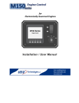
M150 Series Control Panels - Installation / User Manual
2
M150 Series Control Panels - Installation / User Manual
Table of Contents
System Startup ...........................................................................................4
Powering the System ...............................................................................4
Starting the Engine ..................................................................................5
Controlling Engine Speed .......................................................................5
Menu Navigation ....................................................................................5
Main Menu .............................................................................................5
System I/O Indicators ..............................................................................6
System Operation .......................................................................................6
Audible Alerts .........................................................................................6
Contrast Menu ........................................................................................6
Custom Alarms .......................................................................................7
Fault Codes .............................................................................................8
Language ..............................................................................................12
Maintenance Timer ...............................................................................13
Master Reset .........................................................................................14
Passcode ...............................................................................................14
Self-Test ................................................................................................16
Setting Engineering Units ......................................................................17
System Start Up ....................................................................................18
Viewing Data ........................................................................................18
Setting Throttle Type ..............................................................................22
Min/Max Engine Speeds .......................................................................23
Installing the System .................................................................................25
Installation Instructions for Type 2, 3, 3R, 3S, 4, 4X, 5, 6/6P, 12 and 13
(UL-50) Enclosures .......................................................................................25
Engine Connector .................................................................................28
External Engine Shutdown .....................................................................29
Fuel Sender ...........................................................................................29
Oil Pressure Sender ...............................................................................30
Technical Specifications ............................................................................31
System ..................................................................................................31
Factory Settings .....................................................................................31
System Block Diagram ..........................................................................32
Wiring Diagram ....................................................................................33
Connection Details ...............................................................................34
System Components .............................................................................37
Troubleshooting Guide ..............................................................................38
Appendix A - Tier 3 Data Supported ..........................................................39
Appendix B - Menu Overview ...................................................................40
3
M150 Series Control Panels - Installation / User Manual
System Startup
RPM/Gage
System/ICONS
Thro,le
/Increment
Controller
Thro,le
Decrement
Mul&?Color/
Backlight/Display
Keyswitch
Naviga&on
10A/Rese,able/
Circuit/Breaker
Expansion/
Slot
M150L15-54 Shown
Powering the System
The M150L Control Panel is powered from the engine battery connection via the
engine harness connector. Make sure the engine harness is connected to the
M150L before proceeding. To power the system turn the key switch to the “ON”
position. This will activate the control panel and apply power to the engine ECU.
All system sensors will be activated at this time. When the ignition switch is
initially set to the “ON’ position, the digital control system performs a series of
system startup checks. The tachometer needle will sweep from 0 to full range and
then back to zero. After approximately 5 seconds the system startup test will
complete and the digital display will begin to provide system data. Should the
control panel sound an audible alarm OR the digital display indicate a fault
condition do not start the engine. Review the fault condition and proceed to
correct the fault condition. See Fault section of this manual for details on system
faults.
4
M150 Series Control Panels - Installation / User Manual
Starting the Engine
To start the engine, turn the key switch to the “Start” position. Should a fault
condition exist the engine ECU may prevent the engine from starting. If the user
has connected the external engine shutdown and the input is active this will also
prevent the engine from starting. All fault conditions will be indicated by the
digital display. The display will indicate the active fault(s) by presenting a pop-up
graphic describing the fault condition.
Controlling Engine Speed
When the engine is started, the engine speed will be set to the engine minimum
speed setting. To change the engine speed toggle the throttle control (“Fast-Rabbit /
Slow-Turtle”) switch to reach the desired speed setting. The engine speed cannot
be commanded below the minimum setting or above the maximum speed setting.
See section Min/Max Engine speeds for more details.
Menu Navigation
The Mode Button is multi-functional and is used as an escape and enter key. When
the Mode key is pressed for less than 1 second it is considered an escape action.
When pressed for greater than 1 second is considered an enter function. For
example, to enter a menu selection or save an entered value the button must be
pressed and held for greater than 1 second. When escaping a menu selection,
momentary Mode Button presses are used. The only exception to these actions is
entering the main menu. From any runtime data display screen a momentary press
of the Mode Button will activate the main menu.
Main Menu
The Main Menu allows the user to access all areas of the M150L Control System.
To access the Main Menu press the Mode button. To access menu items highlight
the desired selection using the “▼” or “▲” keys and press & hold the Mode
button for 1 second.
5
M150 Series Control Panels - Installation / User Manual
System I/O Indicators
The M150L provides constant monitoring of critical system inputs and indicates
the status of these inputs on the
controller display. The external
Charge/Indicator/Status
engine shutdown, charge indicator
and throttle switch inputs are
External/Engine/Shutdown
assigned to the status icons. The
Thro,le/Switch/Status
presence of the ICON indicates the
input is active.
Note: Charge Indicator and Engine Shutdown inputs will not generate an alarm
indication when engine is not running. However, ICONS will activate if input is
active and engine is not running.
System Operation
Audible Alerts
Audible alerts can be activated for several reasons;
1)
2)
3)
4)
5)
Active Fault(s)
Acknowledged Active Fault reminder
Button Press
Setting Saved
Warning
Audible alerts for button presses, setting saved and warning beeps are configurable
and can be turned on or off from the System / Audio menu. To configure audio
settings enter Main Menu then scroll to System entry using “▼” or “▲”buttons.
Press & hold Mode button for > 1 second to select System menu. Scroll to Audio
entry using “▼” or “▲”buttons. Press & hold Mode button for > 1 second to enter
Audio Menu. Use “▼” or “▲”buttons to select audio menu entry to configure.
Contrast Menu
The Contrast Menu allows the user to adjust the display contrast settings. Enter
Main Menu then scroll to the Contrast entry using “▼” or “▲”buttons.
Select Contrast and adjust contrast using “▼” or “▲” buttons.
6
M150 Series Control Panels - Installation / User Manual
Custom Alarms
Fuel Level
A low fuel warning is configurable by the operator as
a custom alarm. This warning will occur when the
system fuel level drops below the value configured for
this setting. This is a preventative measure to warn the
operator that the fuel level is getting low. Should this
message occur check the fuel level to determine if
sufficient fuel is available. When the fuel level
exceeds the value configured the warning message is automatically removed. This
warning is generated by the control module and does not affect system operation
in any way. This warning will be displayed anytime the fuel level drops below the
level described above.
Note: The fuel level reading must be below the set-point value by .4% for > 10
seconds before alarm will sound. Fuel level reading must be above set-point value
by 2% for > 10 seconds for the alarm to clear.
To select the custom alarm for fuel level enter the Main Menu then scroll to the
System menu entry using “▼” or “▲”buttons. Press & hold Mode button for > 1
second to select the System menu. Scroll to the “CSTM ALARM” entry using “▼”
or “▲”buttons. Press & hold Mode button for > 1 second to enter custom alarm
menu selection (fuel level or oil pressure). Use “▼” or “▲”buttons to select the
desired alarm. Press & hold Mode button for > 1 second to enter the desired
menu. The alarm can be activated or de-activated from the “Status” menu
selection. The alarm set-point is set from the “Value” menu selection.
7
M150 Series Control Panels - Installation / User Manual
Oil Pressure
A low oil pressure warning will occur when the oil
pressure drops below the value configured for this
setting. Should this message occur check the oil level
to determine if the engine has sufficient oil available.
When the oil pressure exceeds the value configured
the warning message is automatically removed. This
warning is generated by the control module and does not affect system operation
in any way. This warning will not be displayed until the operator starts the engine
OR the oil pressure drops below the pressure described above, while the engine is
running.
Note: The oil pressure reading must be below the set-point value by .4% for > 10
seconds before alarm will sound. Oil Pressure reading must be above set-point
value by 2% for > 10 seconds for the alarm to clear.
To select the custom alarm for oil pressure enter the Main Menu then scroll to the
System menu entry using “▼” or “▲”buttons. Press & hold Mode button for > 1
second to select the System menu. Scroll to the “CSTM ALARM” entry using “▼”
or “▲”buttons. Press & hold Mode button for > 1 second to enter custom alarm
menu selection (fuel level or oil pressure). Use “▼” or “▲”buttons to select the
desired alarm. Press & hold Mode button for > 1 second to enter the desired alarm
menu. The alarm can be activated or de-activated from the “Status” menu
selection. The alarm set-point is set from the “Value” menu selection.
Fault Codes
Engine fault codes are generated from the engine ECU and communicated to the
control panel via the CANBus communications link. The control panel reports the
following faults using descriptive text; engine over temperature, low oil pressure,
system charge, water in fuel, and communications failure. The engine ECU can
generate additional fault codes and many engine manufacturers have engine
specific codes. The control panel will present these additional codes as a “Check
Engine” indication along with the SPN Number, FMI Code and fault count. Should
a check engine fault be displayed the operator should access the Fault Code menu
to determine the specific fault condition.
8
M150 Series Control Panels - Installation / User Manual
Active Fault Codes
All active system events (faults and warnings) are displayed on the LCD screen.
Critical faults are backlight in Red. Warnings are backlight in Amber. Fault codes
are accessed from the “Fault Codes” entry in the main menu. When a system fault
occurs the display will activate a pop-up window describing the active fault
condition and sound an audible tone. This pop-up will overlay on top of the
currently active screen.
FAULT
SYSTEM CHARGE
ENGINE
COMMUNICATIONS
CHECK ENGINE
ENGINE
TEMPERATURE HIGH
SYSTEM VOLTAGE
LOW
OIL PRESSURE LOW
EXTERNAL ENGINE
SHUTDOWN
DEFINITION
1,2Alternator
1CANBus
not charging – ECU or M150L generated
network failed – Engine ECU generated
1Engine
Fault – Engine ECU generated
1Engine
Temperature High – Engine ECU generated
1ECU
Voltage Low – Engine ECU generated
1Engine
2Engine
Oil Pressure Low – Engine ECU generated
Oil Pressure Low – M150L Custom Alarm
2External
Engine Shutdown – User generated
Table/1.0/–/System/Alarms
1Engine
ECU may enter rpm limit mode or prevent engine from starting (this
condition is controlled by engine ECU); fault may be generated without engine
running.
2Engine
continues to run – controlled by M150L control module; fault generated
when engine started or engine is running.
System Charge Indicator
A “SYSTEM CHARGE INDICATOR” warning will be
displayed when it is determined the system is
discharging. This condition can occur two ways;
9
M150 Series Control Panels - Installation / User Manual
1)
If configured from the factory, the engine ECU detects the condition and sends
a DM1 message indicating a charge warning Or …..
2)
The M150L Control Module will provide a charge warning when the
alternator field input is indicating a negative current flow. In either condition
the system will indicate an active fault to notify the operator that the system
needs attention.
Engine Communications Failure
An “ENGINE COMMUNICATION FAILURE” is
generated by the engine ECU. This fault occurs when
the throttle speed control message (TSC1) is not
received by the engine ECU at an acceptable update
rate. This is typically 10 msec.
Check Engine
The “CHECK ENGINE” fault is a non-specific fault
condition. This pop-up will occur when the engine
generates any fault condition that is not specifically
described in the fault section of this document. When
a check engine fault occurs it is recommended that
the operator go to the “Fault Codes” menu and review
the detailed engine diagnostic data.
Engine Over-Temperature
The “ENGINE TEMPERATURE HIGH” fault is
generated by the engine ECU which reads a
temperature sender located on the engine. When an
over temperature condition is determined by the ECU
a fault message is transmitted by the engine ECU
indicating an engine temperature above normal exists.
Details about the over temperature alarm can be viewed in the Fault Code menu.
External Engine Shutdown
The “EXTERNAL ENGINE SHUTDOWN” popup will
be generated when the control module has determined
the “External Engine Shutdown” signal is active. When
the external shutdown input is active (connected to
gnd) the M150L Control System will shutdown the
engine by disrupting the ignition voltage. This fault
indication is software generated in the control system.
If the external shutdown is active and the operator tries to start the engine a fault
popup screen will activate indicating the condition exists. This condition will
continue until the fault is removed.
10
M150 Series Control Panels - Installation / User Manual
System Voltage Low
The “SYSTEM VOLTAGE LOW” warning is generated
via the engine ECU. The engine ECU continuously
monitors the ECU supply voltage to determine system
voltage level. Should the system voltage become too
low the engine ECU will indicate voltage below
normal by transmitting a fault message to the control
panel. The engine fault popup screen will indicate that the system voltage is low.
Oil Pressure
The “OIL PRESSURE LOW” critical fault is typically
generated by an oil pressure sender switch mounted
on the engine. The engine ECU reads this switch and
indicates an oil pressure fault OR oil pressure switch
malfunction by transmitting a fault message to the
control panel. The fault message has multiple
definitions and could indicate oil pressure below
normal or oil pressure sensor shorted or open. This message is received by the
control panel and processed to the fault display. The display fault popup screen
will indicate “OIL PRESSURE LOW” when an active oil pressure fault message is
received. Details about the exact oil pressure failure can be viewed from the “Fault
Codes” menu.
Acknowledging Active Faults
When the control system receives a new fault, the digital
display responds by overlaying a fault pop-up graphic
onto the currently active runtime display. This
allows the operator to respond to the fault
condition and provide the necessary actions. The
display to the right represents an
unacknowledged fault for an oil pressure low
condition.
To acknowledge an active fault, press and hold
the Mode button for greater than 1 second. This
will remove the pop-up graphic and silence the
audible fault indication. The control system will
continue to backlight the LCD display indicating an active
fault or warning exists.
Should the fault condition persist and not be acknowledged, the
M150L will “Auto” acknowledge the fault after 1 minute of
continuous fault indication. An auto acknowledge produces the
same result as the user performing an acknowledge.
Press/&/Hold
Mode/Bu,on
>1/second
11
M150 Series Control Panels - Installation / User Manual
Note: If the fault condition is cleared the associated pop-up will automatically be
removed. If the fault condition remains and the fault has been acknowledged, the
audible fault indication will be re-activated every 5 minutes for 2 seconds and then
silence. This feature is a continuous reminder to the operator that a fault is present.
Stored Faults
To access fault codes, enter the Main Menu and then scroll to the Fault Code entry
using “▼” or “▲” buttons. Press & hold Mode button for > 1 second to select the
“Fault Codes” entry. Select “View”. If no fault codes exist the system will indicate
no codes. If codes exist the system will display the SPN number, FMI code and the
number of times the fault has occurred. If multiple faults exist the system will
indicate the number of faults. When more than one fault exists use the “▼” or
“▲” buttons to scroll through the fault code list.
Language
Setting Language
The M150L System provides the user with the ability to select one of 5 languages.
The languages provided are English (default), French, German, Italian and Spanish.
To select a language enter the Main Menu then scroll to the System menu entry
using “▼” or “▲”buttons. Press & hold Mode button for > 1 second to select
System menu. Scroll to “Language” entry using “▼” or “▲”buttons. Press & hold
Mode button for > 1 second to enter Language selection menu. Use “▼” or
“▲”buttons to select the desired language. Press & hold Mode button for > 1
second to enter selected language. M150L will immediately convert to the
language selected.
12
M150 Series Control Panels - Installation / User Manual
Maintenance Timer
The M150L System provides an engine maintenance timer feature. The
maintenance timer display indicates the amount of engine runtime since last
maintenance. If the system is powered but the engine is not running no
maintenance hours will be accumulated. When the maintenance timer exceeds
the configured time, the system will activate an “Engine Maintenance Required”
alert popup. If the timer is not reset the alert popup will reinitiate on each key
“ON” cycle.
Setting Maintenance Timer
The maintenance timer is configurable and resettable by the
operator. The timer will activate when set to a value > 0. To
configure the maintenance timer enter the Main Menu and
then scroll to the Engine entry using the “▼” or “▲”buttons.
Press & hold Mode button for > 1 second to select the
Engine menu. Scroll to the “MAINT TIMER” entry using “▼” or “▲”buttons. Press
& hold Mode button for > 1 second to enter Maintenance Timer Menu. Use “▼”
or “▲”buttons to set maintenance timer hours. Press & hold Mode button for > 1
second to enter the maintenance interval time. The timer has a settable range of
1-9999 hours. A setting of 0 hours turns off the timer.
Acknowledging Maintenance Timer
When the maintenance timer expires the control system will provide an alert
popup indicating the maintenance time has expired. The alert will be cleared
(acknowledged) by pressing and holding the Mode button. See acknowledging
active faults section for more details. Accessing the maintenance timer reset menu
via the “Hot Key” will also acknowledge the maintenance timer alert.
Resetting Maintenance Timer
To reset the maintenance timer enter the Main Menu and then scroll to the “RST
MAINT TIMER” entry using the “▼” or “▲”buttons. Press & hold Mode button for
> 1 second to select reset maintenance timer menu. Using the “▼” or “▲”buttons
select “YES” to reset the timer. Press & hold Mode button for > 1 second to enter
the timer reset request.
13
M150 Series Control Panels - Installation / User Manual
Resetting the maintenance timer can also be accomplished using an M150L builtin “Hot Key”. The “Hot Key” entry is accomplished by simultaneously pressing the
“▼” or “▲”buttons.
Simultaneous/pressing/will/
cause/Hot/Key/to/ac&vate
Master Reset
A Master Reset allows the user to set the M150L back to factory default settings.
Settings such as Language, Fuel Setup, Oil Pressure Sender, Throttle Type,
Engineering Units will all be reset to their factory setting when a master reset is
completed.
To select Master Reset enter the Main Menu and then scroll to the System entry
using “▼” or “▲”buttons. Press & hold Mode button for > 1 second to select
System menu. Scroll to “Master Reset” entry using “▼” or “▲”buttons. Press &
hold Mode button for > 1 second to activate the master reset program. The M150L
will require two user confirmations before proceeding with the master reset
application.
Passcode
The M150L allows the user to set a passcode which protects various parameters in
the M150L database. Setting the passcode to 0000 will disable it. Any non-zero
value for the passcode entry enables it and therefore protects critical data
parameters.
To select Passcode enter the Main Menu then scroll to the System entry using “▼”
or “▲”buttons. Press & hold Mode button for > 1 second to select System menu.
Scroll to “Passcode” entry using “▼” or “▲”buttons. Press & hold Mode button for
> 1 second enter passcode menu. The passcode menu allows the user to Disable
or Change the current passcode configuration.
14
M150 Series Control Panels - Installation / User Manual
Changing the Passcode.
When the passcode protection is enabled the M150L will prevent changes to the
following parameters;
Display Menu
# of Screens
Screen Setup
Engine Menu
Throttle Type
Oil Pressure Sender Source
Set Min RPM
Set Max RPM
Maintenance Timer
Fuel Setup Menu
Fuel Sender Source
System Menu
Custom Alarms
Master Reset
Passcode
Note: When changing or Enabling the passcode, the changes will not go into effect
until the system has seen a power cycle.
Disabling the Passcode.
Enabling the Passcode.
15
M150 Series Control Panels - Installation / User Manual
Self-Test
The self-test program allows the user to verify several areas of system operation.
The areas tested are; dial/pointer/LCD backlight intensity, LCD backlight color
(red, green, blue, white) , alarm LEDs, pointer movement (full-scale, mid-scale, 0),
non-volatile (NVM) memory, buzzer and communications channel (CAN).
16
M150 Series Control Panels - Installation / User Manual
To select Self-Test enter the Main Menu and then scroll to the System entry using
“▼” or “▲”buttons. Press & hold Mode button for > 1 second to select System
menu. Scroll to “Self-Test” entry using “▼” or “▲”buttons. Press & hold Mode
button for > 1 second to activate the Self-Test program.
Setting Engineering Units
Engineering units can be configured for the entire M150L System or individual unit
categories.
To select engineering units enter the Main Menu and then scroll to the System
entry using “▼” or “▲”buttons. Press & hold Mode button for > 1 second to select
System menu. Scroll to the “Set Units” entry using “▼” or “▲”buttons. Press &
hold Mode button for > 1 second to enter “Set Units” menu. Use “▼” or
“▲”buttons to select the desired configuration. Press & hold Mode button for > 1
second to configure the selected entry. The M150L will immediately convert to the
engineering units selected.
17
M150 Series Control Panels - Installation / User Manual
System Start Up
When powered the control panel digital display will show an introductory splash
screen showing product model number, system revision level and date. (See
display bottom left.) During this time a system self-check will be performed and
the tachometer needle will complete a full sweep of the dial range. This will take
approximately 5 seconds at which time the LCD display will present the default
runtime data screen. As shipped from the factory the default runtime display is
configured to present oil pressure. (See display bottom right.) The system is
preconfigured to provide 9 data displays. As shipped from the factory, the Oil
Pressure screen is displayed on startup after presenting the splash screen. The
additional Viewing List of displays may be presented by pressing the “▼” or “▲”
buttons. See Viewing Data section for description of all display information.
Should any Engine Fault be active on startup a fault pop-up window will be
displayed. See Faults section for more information.
Viewing Data
As shipped from the factory, the M150L contains 9 data displays in the viewing
list. These displays can be accessed via the “▼” and “▲” buttons from the runtime
menu. This list is called the “Viewing List”. The maximum number of displays that
can be configured in the “Viewing List” is 18.
Default Startup Display
To configure a particular display as the default startup display, access the desired
display from the viewing list and leave active for 5 minutes. The M150L system
will automatically set this display as the default display.
Configuring Display View List
The M150L allows the user to configure a list of displays for viewing. The “Viewing
List” is selected from the list of System Displays. Any display contained in the
“System Display List” can be assigned to any screen location in the “Viewing List”.
To access the Display View List setup, enter Main Menu then scroll to Display
entry using “▼” or “▲” buttons. Press & hold Mode button for > 1 second to
select the “Display” entry. Use the “▼” or “▲” buttons to select a particular
viewing list entry.
18
M150 Series Control Panels - Installation / User Manual
View List Screen Count
To configure the number of screens in the View List enter display menu then scroll
to “# Of Screens” entry using “▼” or “▲” buttons. Press & hold Mode button for >
1 second to select. Set screen count using “▼” or “▲” buttons. Press & hold Mode
button for > 1 second to enter screen count number.
View List Screen Setup
To configure data displays for the viewing list, enter display menu then scroll to
“Screen Setup” entry using “▼” or “▲” buttons. Press & hold Mode button for > 1
second to select. Select screen # to be configured using “▼” or “▲” buttons. Press
& hold Mode button for > 1 second to select. Select data display using “▼” or
“▲” buttons. Press & hold Mode button for > 1 second to enter data display.
See System Display List for a complete list of available data displays.
19
M150 Series Control Panels - Installation / User Manual
Default Viewing List
20
M150 Series Control Panels - Installation / User Manual
System Display List
21
M150 Series Control Panels - Installation / User Manual
Bar Graph Data
The M150L has the ability to display select data parameters in bar graph form.
When activated this feature allows the user to simultaneously display, at the
bottom of the screen, the selected data on all screens contained in the “Viewing
List”.
Example; Fuel Level Bar Graph Data.
To select the Bar Graph data display enter display menu then scroll to “Bar Graph
Data” entry using “▼” or “▲” buttons. Press & hold Mode button for > 1 second
to select. Select data to be viewed using “▼” or “▲” buttons. Press & hold Mode
button for > 1 second to enter data selection. Fuel level and engine load can be
selected.
Select Bar Graph Data
Setting Throttle Type
The M150L provides two types of throttle operation, Ramp and Two-State. To
access Throttle Type configuration, enter the Main Menu and then scroll to the
“Engine” entry using “▼” or “▲” buttons. Press & hold Mode button for > 1
second to select the “Engine” Menu. Scroll through the “Engine” menu using “▼”
or “▲” buttons until Throttle Type is highlighted. Press & hold Mode button for > 1
second to select the “Throttle Type”.
22
M150 Series Control Panels - Installation / User Manual
Ramp Throttle Operation
Ramp throttle operation allows the user to increment or decrement the desired
engine RPM value by 10 RPM. To increment engine rpm simply press the throttle
switch in the “Rabbit” position. Pressing the throttle switch in the “Turtle” direction
will decrement the engine speed by 10 rpm. Holding the throttle switch in the
“Rabbit” or “Turtle” position for > 2 seconds will cause the algorithm to speed up
and the engine speed will increment or decrement at a rate of 50* RPM / second.
Note: The user cannot adjust the engine speed above or below the configured
“Min” and “Max” engine speed settings. See section, Min/Max Engine Speeds for
more details.
2-State Throttle Operation
Two state throttle operation allows the operator to quickly choose between two
predetermined engine speeds at the single touch of the throttle control. The two
predetermined engine speeds are defined by the rpm value configured in the
Engine Settings menu for “Min” speed and “Max” speed. Pressing the throttle
control in the “Rabbit” position sets the engine rpm to the configured “Max” speed
setting. Pressing the throttle control in the “Turtle” position sets the engine rpm to
the configured “Min” speed setting.
CAUTION: Changes to settings in the “Engine” menu will take affect while the
engine is running. Any change to throttle type setting or engine min/max settings
will become active after the change is saved AND a throttle command is issued.
Min/Max Engine Speeds
The M150L allows the user to configure minimum and maximum engine rpm
limits. The minimum engine rpm value is determined by the “Min” speed setting in
the Engine menu. The maximum engine rpm value is determined by the “Max”
speed setting in the Engine menu. Once configured the M150L prevents the user
from throttling the engine above or below these values.
Min Engine Speed
To access the “Set Min RPM” setting, enter the Main Menu. Scroll to the “Engine”
menu entry using “▼” or “▲” buttons. Press & hold Mode button for > 1 second
to select the “Engine” menu entry. Scroll through the “Engine” menu using “▼” or
“▲” buttons until “Set Min RPM” entry is highlighted. Press & hold Mode button
for > 1 second to select the idle speed entry. Use the “▼” or “▲” buttons to set
the minimum engine rpm value. Press & hold Mode button for > 1 second to enter
the Min RPM speed entry.
23
M150 Series Control Panels - Installation / User Manual
Max Engine Speed
To access the “Set Max RPM” setting, enter the Main Menu. Scroll to the “Engine”
menu entry using “▼” or “▲” buttons. Press & hold Mode button for > 1 second
to select the “Engine” menu entry. Scroll through the “Engine” menu using “▼” or
“▲” buttons until “Set Max RPM” entry is highlighted. Press & hold Mode button
for > 1 second to select the run speed entry. Use the “▼” or “▲” buttons to set the
maximum engine rpm value. Press & hold Mode button for > 1 second to enter the
Max RPM speed entry.
24
M150 Series Control Panels - Installation / User Manual
Installing the System
Installation Instructions for Type 2, 3, 3R, 3S, 4, 4X, 5, 6/6P, 12 and 13
(UL-50) Enclosures
File #E207562/E229365 - Integra® Enclosures
Mounting Brackets
A mounting bracket and screw pack are provided with the Premium enclosures. To
assemble, turn the enclosure upside down on aflat surface, place the mounting
bracket over the square boss either horizontally or vertically, and fasten the
mounting bracket with the '1/4”-20 x0.25" SS, countersunk Phillips drive screws
(torque limit = 20 in. lbs.). The enclosure can be mounted either horizontally or
vertically, with the mounting brackets in any configuration, using any acceptable
fastening technique.External mounting means are provided and molded into
enclosures.
Covers/Doors
Covers/doors have a gasket pre-assembled to seal against the base. Attach to the
base in these three standard configurations:
Non-Hinged Junction Pull Box:
Screw down in four comers with screws provided. Torque for comer screws is 10
inch-pounds. (Required for type 6P Rating)
Externally Hinged Cutout Box:
Externally hinged along one side of the major dimension of the enclosure with
opposite side to the hinge screwed down with(2)# 10-32 x 0.75” SS, pan Phillips
drive screws (4X rating). To achieve 6P rating - all 4 screws will be used and
torqued to 10 inch-pounds (this applies to the Premium line).
Externally hinged along one side of the major dimension of the enclosure with
opposite side to the hinges held by lockout-type latches.
Enclosures are provided with cover/door assembled to the base. For Premium
lines, #10-32 x 0.75" SS, Phillips drive screws are provided to secure the cover/
door to the base. When re-assembling, be sure to align gasket on cover/door with
the sealing bead on the base.
Note: When starting and tightening screws, it is easiest to align and tighten screws
by first starting all four screws, then tightening opposite corner screws to 10 inchpounds.
When used as a Pull Box, installation in the U.S. shall be in accordance with
Section 314-28 of the National Electric Code, ANSI/NFPA 70-2008. Installation in
Canada shall be in accordance with Section 12-3036 of the Canadian Electrical
Code, C22.1-2006.
25
M150 Series Control Panels - Installation / User Manual
Installation Instructions Notes:
(Premium and Impact Lines)
Installation of Conduit
Conduit holes can be cut using standard hole Locations are as desired per any
applicable rules or codes.
Enclosures marked with a model type 6/6P rating require installation instructions
that specify the use of UL approved conduit hubs. Maximum Hub size for
G242410 and H181610 is 3" all other enclosures is 2". Any hub must be mounted
on a flat surface.
Metallic Conduit
Secure the conduit connector into the conduit. Then secure the conduit connector
into the pre-drilled hole in the enclosure with the connector locknut. Then secure
the grounding bushing over the connector locknut.
Nonmetallic Conduit
Either assemble the conduit connector into the conduit,or the pre-drilled hole in
the enclosure, whichever is easier, and secure with the connector locknut.
Grounding of Conduit
Any metallic conduit joining an enclosure must be grounded. Use Grounding Kit
GK001.
1)
All threaded inserts in the enclosure and for cover attachment are . #10-32.
2)
Bonding between grounding bushings/lugs or between the grounding
bushings/lugs and the devices installed inside the enclosure must be
according to applicable governing Electrical Code.
3)
Enclosure drilled for conduit or other modifications voids warranty and may
not be returned.
4)
Conduit must be aligned into or out of enclosure to prevent enclosure
damage due to bending stress on enclosure walls.
5)
Do not use PVC cement to connect fittings to enclosure.
6)
Any fittings used , including conduit fittings, must be according to applicable
Electrical Code and must maintain integrity of UL rating.
7)
If the enclosure is provided with customer-specified modifications, the
openings must be filied with listed fittings/components of the same
environmental rating.
8)
Type 2 and 3R if fitted with drain opening 1/8" min. to 1/4' max, located in
the lowest part of the bottom wall.
26
M150 Series Control Panels - Installation / User Manual
Making the Connections
The control panel has one round connector with 21 contacts. This connector is an
HDP24 Deutsch connector and provides the connection to the engine connector.
(Note: Some engine may require an interface harness for this connection. Contact
MBW Technical Support Team for details.) This connector also provides the user
connections for fuel level, oil pressure and external engine shutdown. The supply
power MUST be OFF when interconnecting the system.
Recommended order:
1)
Verify the battery / battery switch connections to engine per the engine
installation diagram. (Refer to engine manufacturer installation manual.) Verify
engine is bonded to battery return (-). Verify engine block is connected to
battery ground.
2)
Disconnect battery.
3)
Install control panel into housing. Attach engine connector to housing using
supplied locknut and ring.
4)
Fasten control panel to housing using #8 8-32 screws (not supplied).
5)
Connect engine harness connector to mating control panel connector
(HDP24-21 connector).
6)
Connect battery.
7)
Turn ignition key to “ON” position.
8)
Ensure digital display is active. If display is not active;
9)
Check battery and power connections.
10) Check the control panel resettable breaker.
11) Check ignition switch is on position.
12) Ensure system is displaying data for engine speed, oil pressure and
temperature.
27
M150 Series Control Panels - Installation / User Manual
Adding Additional Gauges
The M150L allows the user to enhance the data viewing capability of the system
by simply adding Plug N’ Play analog gauges to the main controller module. The
installation is simple requiring an interconnect cable (PN: HN0503) and the data
gauge of choice. To add an analog gauge to the system plug the first gauge into the
main controller harness using (PN:1000116-10). Any remaining gauges to be
added will be serially connected by using harness HN0503. It is recommended
that the last gauge in the sequence plug the unused connector with a dummy plug
(PN:PJ0036). See system components section for gauge types offered.
Engine Connector
The engine connector is labeled “Engine” and requires no
additional wiring. This connector mates directly to the onengine harness connector. The table below describes the
engine harness connections, associated connector pin
number and wire color.
28
Desc
PIN
Number
Engine Harness
Connector – P2
Size
Wire Color
N/C
A
Pre-Heat Lamp
16 AWG
Tan
B+
B
Battery + (10A)
16 AWG
Red
N/C
C
Sensor Return
16 AWG
Black
Start
D
Starter (30)
16 AWG
Red/Black
Ground
E
Ground
16 AWG
Black
ECU Power (Ignition)
16 AWG
Purple
Accessory (15)
16 AWG
Pink/Black
Green/Black
N/C
F
Ignition Out
G
N/C
H
Key Acc
J
N/C
K
N/C
L
N/C
M
Fuel Level
N
Fuel Level Sender
16 AWG
Oil Pressure
P
Oil Pressure Sender
16 AWG
Orange
Charge In
R
Charge Lamp
16 AWG
Dark Green
RS232 TX
S
16 AWG
White
RS232 RX
T
16 AWG
Blue
CAN Lo
U
CAN Low (twisted pair)
16 AWG
Light Green
CAN Hi
V
CAN High (twisted pair)
16 AWG
Yellow
N/C
W
16 AWG
White/Blue
ESTOP
X
16 AWG
Blue
External Engine Stop
M150 Series Control Panels - Installation / User Manual
External Engine Shutdown
To connect the external engine shutdown to the M150L install the engine
shutdown (Blue) wire in the ‘X’ terminal of the engine connector. This is supplied
with the external wire set PN:1000130-00. Connect the engine shutdown signal to
this wire. This input requires a closure to ground. See Engine Connector wiring
table for wiring details.
Fuel Sender
To connect the fuel level sender to the M150L install the Green/Black wire,
supplied in wire set PN:1000130-00, in the ‘N’ terminal of the engine connector.
Connect the fuel level sender to this wire. See Engine Connector wiring table for
wiring details.
Note: The fuel level measurement algorithm is designed to provide enhanced
filtering when the engine is running. When the engine is not running the algorithm
filtering is reduced allowing for improved response when adding fuel to the tank.
Fuel Sender Specification
The M150L Control Panel interfaces with any standard 240-33 ohm US or 10-180
ohm Euro Sender. The system can be configured for operation with either sender or
CANBus Data.
The M150L can be configured to measure analog senders or receive fuel data via
Bus Data (i.e CANBus). If Bus Data is providing the source for fuel level data
choose “BUS DATA” as the fuel setup input. See Appendix A for definition of Fuel
Level message.
Configuring the Fuel Level Input
To configure the fuel sender, enter the Main Menu. Scroll to the “Fuel Setup”
menu entry using “▼” or “▲” buttons. Press & hold Mode button for > 1 second
to select “Fuel Setup”. Scroll through the “Fuel Setup” menu using “▼” or “▲”
buttons to select the desired fuel tank. Press & hold Mode button for > 1 second to
select the desired fuel tank. Use the “▼” or “▲” buttons to select the fuel sender.
Should the sender not be installed or no connection made, the digital display will
indicate “NO DATA“ for the fuel level measurement value.
29
M150 Series Control Panels - Installation / User Manual
Oil Pressure Sender
To connect the oil pressure sender to the M150L install the Orange wire, supplied
in wire set PN:1000130-00, in the ‘P’ terminal of the engine connector. Connect
the oil pressure sender to this wire. See Engine Connector wiring table for wiring
details. A small filtering algorithm is applied to the oil pressure measurement when
an analog sender is used. The filtering removes momentary spikes in data as a
result analog sender response times.
Oil Pressure Sender Specification
The M150L Control Panel interfaces with a VDO 10-180 ohm Oil Pressure Sender.
The system can be configured for 0-5 Bar or 0-10 Bar operation.
Note: The M150L can be configured to measure analog senders or receive oil
pressure data via Bus Data (i.e. CANBus). If Bus Data is the source for oil pressure
choose “BUS DATA” as the oil pressure input. See Appendix A for definition of Oil
Pressure message.
Configuring Oil Pressure Input
To configure the system to read an external oil pressure sender, enter the Main
Menu. Scroll to the “ENGINE” menu entry using “▼” or “▲” buttons. Press &
hold Mode button for > 1 second to select the “ENGINE” menu. Scroll through the
“Engine” menu using “▼” or “▲” buttons to “Oil Pressure Src”. Press & hold
Mode button for > 1 second to select the oil pressure source menu. Use the “▼”
or “▲” buttons to select the oil pressure sender.
Should the sender not be installed or no connection made, the digital display will
indicate “NO DATA“ for the oil pressure value. Oil Pressure alarms are typically
provided by the Engine ECU. The M150L can be configured to provide a Low Oil
Pressure alarm. See Custom Alarms section for more details. The custom alarm for
oil pressure will not be active if a sender input is not available.
30
M150 Series Control Panels - Installation / User Manual
Technical Specifications
System
Display
Resolution
Operating Voltage
Color LCD
128 x 64 pixels
10.5 to 18VDC
Power Consumption – Tachometer
400 mA max
Power Consumption – Gauge Bus
90 mA max per gauge
Audible Alarm
External Engine Shutdown
Communication
Operating Temperature
Storage Temperature
Reverse Polarity Protection
Salt Spray
EMC
Dimensions (MGT020 Gauge only)
Dimensions (MGT021 Gauge only)
System Protection
4 KHZ Internal
Closure to Gnd
J1939
-20C to +70C (-4F to 158F)
-30C to +85C (-22F to 185F)
Yes
IEC60068-2-52: 1996
IEC61000 and EN55022
3.375” Dia x 4.29”
4.375” Dia x 4.18”
10A Resettable Circuit Breaker
Factory Settings
The following system settings will take affect when a master reset is applied.
PARAMETER
Display Settings
# of screens
Viewing List configuration
Bar Graph
Auto Scroll
Engine Settings
Engine Idle
Engine Run
Throttle Type
Oil Pressure Sender Source
Maintenance Timer
Fuel Setup
Fuel Sender Source
System
Custom Alarms
Language
Set Units
DEFAULT VALUE
9
See Default Viewing List
Off
Off
1000 RPM
3200 RPM
RAMP Mode
10-180 (10 Bar)
0 Hours (off)
240-33 ohm (USA Sender)
Off
English
USA units
31
M150 Series Control Panels - Installation / User Manual
System Block Diagram
External&Engine&Stop
<
(DI&&&Stop&Active&Low)
Engine&
Harness
>
Oil&&&&Pressure&(P)
Fuel&(N)
Battery
32
Fuel&Tank
M150 Series Control Panels - Installation / User Manual
Wiring Diagram
33
M150 Series Control Panels - Installation / User Manual
Connection Details
Control Harness
PN:1000116-00 The main control harness provides connections from the engine
to the main controller (tachometer), throttle switch, key switch, circuit breaker and
external engine shutdown.
Circuit Breaker
Connection
Engine Shutdown
P2
GND
P1
P4
P3
Throttle Switch
Control Harness PN:1000116-00
Control Harness Connector Details
Connector
Description
P1
6 Pin; connects to key switch, blk
P2
Engine connector
P3
6 Pin; connects to controller, gry
P4
12 Pin; connects to controller, gry
Black Quick Connect
White/Red Quick Connect
Brown Quick Connect
Red Quick Connect
Upper (rabbit) position of throttle switch
Center position of throttle switch
Lower (turtle) position of throttle switch
Battery; connection for resettable 10A breaker
(resettable breaker not included in all models)
Wire Set – OP / Fuel Level / Engine Shutdown
PN:1000130-00 Engine connector (P2) wire set. Wire set allows connection of
analog oil pressure sender, analog fuel level sender and external engine shutdown
via connector P2.
Wire Color
Description
P2 Position
Orange
Oil Pressure
‘P’
Blue
Grn/Blk
34
External Shutdown
‘X’
Fuel Level
‘N’
M150 Series Control Panels - Installation / User Manual
PN:1000116-10 Serial gauge Bus extension harness provides the ability to expand
the system display capability. This is accomplished by adding parameter specific
2” gauges to the main controller. No configuration is necessary. Just plug the
expansion gauge into the harness and the data will be available. To install the
extension harness connect the gnd of the 116-10 harness to the mating gnd
connector on the 116-00 harness. Insert the gauge bus communications and
power pins into the P4 connector of the 116-00 harness.
To Connector P4
GND
Gauge
PN:1000116-10 Serial Gauge bus harness
Serial Gauge Bus Connector Details
Wire Color
Description
Red
P4 Pin #
Power
1
White
Serial Gauge Bus A
2
Green
Serial Gauge Bus B
3
Control Harness w/Gauge Bus Extension
Circuit Breaker
Connection
Engine Shutdown
P2
P1
GND
P3
Throttle
P4
Gauge
Harness PN:1000116-50
35
M150 Series Control Panels - Installation / User Manual
Connecting a Switch Gauge
The L15 Series panel provides expansion slots to allow application specific gauges
to be field installed. Application specific switch gauges are commonly used to
provide an external engine shutdown signal. The external engine shutdown
requires a contact closure to ground to activate the engine shutdown signal. To
connect a switch gauge to the external engine shutdown the M150L provides
quick connect terminals in the control harness for easy installation.
Quick Connect
Ground
Quick Connect Pin
86 Engine
Shutdown Relay
Circuit Breaker
Connection
Engine Shutdown
P2
P1
GND
P3
Throttle
P4
Gauge
Harness PN:1000116-50
Connect the switch gauge contact (or lead terminal) to Pin 86 of the engine
shutdown relay. Connect the switch gauge ground (this is typically the gauge
housing) to the M150L ground connection shown above. When the switch gauge
set point is reached the engine shutdown relay will activate and shutdown the
engine.
36
M150 Series Control Panels - Installation / User Manual
System Components
PART NUMBER
DESCRIPTION
C1121/12 Boot;/Pushbu,on,/Blk
CLB10311B3ABA Breaker;/10A,/w/o/Boot
GE0171 Gauge;/2”,/Fuel/Level,/M150L/Series
GE0172 Gauge;/2”,//100/PSI/Oil/Press,/M150L/Series
GE0173 Gauge;/2”,//250/Deg/Wtr/Temp,/M150L/Series
G8JN1C7TMFDC12 Relay;/12v,/SPNO
HN0503 Harness;/2”/Gauge/to/Gauge,/Faria/Bus
M150L00?00 Kit;/Eng/Ctrl,/J1939,/T3,/4”?4K
M150L00?50 Kit;/Eng/Ctrl,/J1939,/T3,/5”?4K
M150L01?00 CP;/Eng/Ctrl,/J1939,/T3,/4”?4K,/8x6,/AL,/PNL/MNT
M150L01?50 CP;/Eng/Ctrl,/J1939,/T3,/5”?4K,/8x6,/AL,/PNL/MNT
M150L10?00 CP;/Eng/Ctrl,/J1939,/T3,/4”?4K,/8x7/STEEL/ENCL
M150L10?50 CP;/Eng/Ctrl,/J1939,/T3,/5”?4K,/8x7/STEEL/ENCL
M150L15?00 CP;/Eng/Ctrl,/J1939,/T3,/4”?4K,/8x13/STEEL/ENCL
M150L15?03 CP;/Eng/Ctrl,/J1939,/T3,/4”?4K,/8x13/STEEL/ENCL,/OP/TEMP/V
M150L15?04 CP;/Eng/Ctrl,/J1939,/T3,/4”?4K,/8x13/STEEL/ENCL,/OP/TEMP/V/FUEL
M150L15?50 CP;/Eng/Ctrl,/J1939,/T3,/5”?4K,/8x13/STEEL/ENCL
M150L15?53 CP;/Eng/Ctrl,/J1939,/T3,/5”?4K,/8x13/STEEL/ENCL,/OP/TEMP/V
M150L15?54 CP;/Eng/Ctrl,/J1939,/T3,/5”?4K,/8x13/STEEL/ENCL,/OP/TEMP/V/FUEL
M150L20?00 CP;/Eng/Ctrl,/J1939,/T3,/4”?4K,/NEMA/4X/ENCL
MGT020 Gateway;/4”?4K/Tach,/J1939/Ctrl
MGT021 Gateway;/5”?4K/Tach,/J1939/Ctrl
MN10027?00 Manual;/User/Install,/M150L/Series
MN10028?00 Manual;/Moun&ng/Template,/M150L00/Series
PJ0036 Plug;/Sealing,/4/Pin/Packard
VE0028 Gauge;/2”,//Volt,/M150L/Series
1000017?23 Keyswitch;/4/pos,/ACC?OFF?ON?START,/common/key
1000107?00 Switch;/Rocker,/(ON)?OFF?(ON)
1000116?00 Harness;/Control,/M150L
1000116?10 Harness;/Control/to/Faria/Bus,/M150L
1000116?50 Harness;/1000116?00/and/1000116?10//assembly
1000130?00 Wire/Set;/OP/Fuel/Shutdown
1080002?01 Plug;/Dome,/1/2”/Dia,/Blk
1080002?02 Plug;/Dome,/3/4”/Dia,/Blk
1080002?03 Plug;/Dome,/2.063”/Dia,/Blk
37
M150 Series Control Panels - Installation / User Manual
Troubleshooting Guide
Symptom
Action
Key “ON”; No display or alarm sounded ! Verify Battery is connected and battery
switch, if installed, is in “ON” position.
! Check engine fuse. If fuse blown check
engine wiring.
! Check engine harness connection at
control panel.
! Reset circuit breaker
Key “ON”; No display or alarm
sounded; Tachometer backlight
flashing; No throttle control.
! Check engine harness connection at
control panel. Engine connector pin W
is improperly wired. Pin W MUST be
open.
Key “ON”; Alarm sounded but no
display.
! Check display contrast/lighting level
! Replace tachometer gauge
Key “ON”; Display “ON”; Engine data is ! Check Engine harness connections.
missing or intermittent.
! Check main fuse on engine.
! Check for active alarms.
! Check Diagnostic Trouble Codes.
Key “ON”; Display active and showing
data but Engine will not start
! Check for system alarms.
! Check Diagnostic Trouble Code screen
for engine faults.
! Check external engine shutdown input.
Key “ON”; Display active, no engine
data, Engine will not start
! Check for system alarms.
! Check Diagnostic Trouble Code screen
for engine faults.
! Check remote engine shutdown input.
! Replace Control Panel.
Engine will Not Start; ”External Engine ! External Engine Stop input is active.
Stop” Fault
38
FAST / SLOW throttle switch does not
change engine speed.
! Engine Fault. Check DTC screen for
specific engine failure.
! Ensure Engine Speed settings do not
exceed engine manufacturer
recommendations.
Engine Speed will not ramp.
! Check User Setting menu. Throttle
Type set for 2-State.
M150 Series Control Panels - Installation / User Manual
Appendix A - Tier 3 Data Supported
Description
Identifier
PGN
Active DTCs
DM1
65226
Active DTCs (emissions related)
DM12
65236
Ambient Temperature
AMB
65269
171
Barometric Pressure
AMB
65269
108
Battery Potential Switched
VEP
65271
158
Battery Potential
VEP
65271
168
EFL/P1
65263
111
ET1
65262
110
Previously Active DTCs
DM2
65227
Previously Active DTCs (emissions)
DM23
64949
ET2
65188
1136
HOURS
65253
247
Coolant Level
Coolant Temperature
ECU Temperature
Engine Hours
Fuel Level
SPN
DD
65276
96
Fuel Pressure
EFL/P1
65263
94
Fuel Rail #1 Pressure
EFL/P2
65243
157
Fuel Rail #2 Pressure
EFL/P2
65243
1349
Fuel Rate
LFE
65266
183
Fuel Temperature
ET1
65262
174
EEC1
61443
92
IC1
65270
102
Load
Manifold Pressure
Manifold Temperature
IC1
65270
105
Oil Level
EFL/P1
65263
98
Oil Pressure
EFL/P1
65263
100
EEC1
61444
190
OI
65279
97
RPM
Water in Fuel Indication
39
M150 Series Control Panels - Installation / User Manual
Appendix B - Menu Overview
Main Menu
Contrast Menu
Display Menu
Engine Menu
40
M150 Series Control Panels - Installation / User Manual
Lighting Menu
Fault Codes
Fuel Setup
Reset Maintenance Timer
System
41
M150 Series Control Panels - Installation / User Manual
Index
Active alarm..........................................6
Adding analog gauges.........................28
Audible Alerts .......................................6
Auto Acknowledge..............................11
Bar Graph Data ...................................22
Configuring Viewing List ...................19
Connecting a Switch Gauge................36
Contrast .................................................6
Control Harness ..................................33
Controlling Engine Speed .....................5
Custom Alarms .....................................7
Fuel Level .......................................7
Oil Pressure.....................................8
Default Startup Display ......................18
Display View List .........................18, 19
Enclosure Installation ...................25, 26
Enter Button ..........................................5
Escape Button .......................................5
External Engine Shutdown ...........10, 29
Fault Codes ...........................................8
Faults
Acknowledging Active Faults .......11
Active Fault Codes .........................9
Check Engine ............................8, 10
Critical faults ..................................9
Engine Communications Failure...10
Engine Over-Temperature.............10
External Engine Shutdown ...........10
Oil Pressure ...................................11
Stored Faults .................................12
System Voltage Low .....................11
Fuel Level Measurement ....................29
Fuel Sender .........................................29
Hot Key...............................................14
Language Selection .............................12
Main Engine Connector ......................28
Main Menu ...............................5, 12, 29
Maintenance Timer
Acknowledge ................................13
42
Hot Key Access.............................14
Resetting .......................................13
Master Reset .......................................14
Max Engine Speed ..............................23
Menu Navigation
Contrast Menu ..............................40
Display Menu ...............................40
Engine Menu.................................40
Fault Codes ...................................41
Fuel Setup .....................................41
Lighting Menu ..............................41
Main Menu ...................................40
Reset Maintenance Timer .............41
System...........................................41
Min Engine Speed ..............................23
Mode Button .........................................5
Oil Pressure Measurement ..................30
Oil Pressure Sender.............................30
Passcode..............................................14
Changing .......................................15
Disable ..........................................15
Enable ...........................................15
Serial Gauge Bus ................................35
Setting Engineering Units ...................17
System ICONs
Charge Indicator..............................6
external engine shutdown ...............6
Throttle Switch ...............................6
Throttle Types
Ramp .......................................22, 23
Two State ................................22, 23
View List Screen Count ......................19
Viewing Data ......................................18
Warnings
Low Fuel .........................................7
System Charge ................................9
Wire Set OP/Fuel/Shutdown ...............35
M150 Series Control Panels - Installation / User Manual
MBW-Technologies, LLC (2 – Year) Limited Warranty
MBW Technologies, LLC (“MBW”) warrants its Electronic Module, Display
products, Electrical Cable and Electrical Connector products to be free
from defects in materials and workmanship for a period of two (2) years
from the date of shipment by MBW. Within this period, MBW will, at its
sole option, repair or replace any Electronic Module or Display that fails in
normal use and is returned to MBW (freight prepaid) within the warranty
period. MBW is not responsible for charges connected with the removal of
such product or reinstallation of replacement or repaired parts. This
warranty does not cover failures due to abuse, misuse, accident, faulty
installation or unauthorized alteration or repairs.
THE EXPRESS WARRANTY SET FORTH ABOVE IS IN LIEU OF ALL OTHER
WARRANTIES, EXPRESS OR IMPLIED, INCLUDING BUT NOT LIMITED
TO THE IMPLIED WARRANTIES OF MERCHANTABILITY AND FITNESS
FOR A PARTICULAR PURPOSE.
Statements made by any person, including representatives of MBW, which
are inconsistent or in conflict with the terms of this Limited Warranty, shall
not be binding upon MBW unless reduced to writing and approved by an
officer of MBW.
IN NO EVENT SHALL MBW BE LIABLE FOR ANY INCIDENTAL, SPECIAL,
INDIRECT, OR CONSEQUENTIAL DAMAGES, WHETHER RESULTING
FROM THE USE, MISUSE OR INABILITY TO USE THIS PRODUCT OR
FROM DEFECTS IN THE PRODUCT. Some states do not allow the
exclusion of incidental or consequential damages, so the above limitation
may not apply to you. MBW retains the exclusive right to repair or replace
the electronic module or display or offer a full refund of the purchase price
at its sole discretion. SUCH REMEDY SHALL BE YOUR SOLE AND
EXCLUSIVE REMEDY FOR ANY BREACH OF WARRANTY.
Warranty Return Procedure:
To obtain warranty service, contact MBW Technologies, LLC Technical
Support Department at (267) 932-8573 x341 or email
[email protected] to describe problem and determine appropriate
action.
43
M150 Series Control Panels - Installation / User Manual
44