1
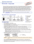
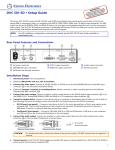
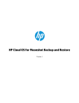
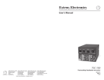
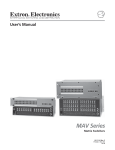
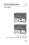
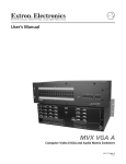
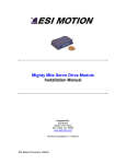
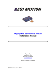
MMX 32 VGA MTP • Setup Guide RJ-45 Connector Pins: 12345678 OUTPUT 1 1 OUTPUT 2 2 3 1 2 3 MMX 32 VGA MTP AUDIO INPUT 3 OUTPUT 2 AUDIO 1 1 AUDIO L R 2 3 +5V CONTACT RGB/AUDIO POWER 12V 0.5A MAX REMOTE SYNC - TRI PRE PEAK - ON INPUT 1 Insert Twisted Pair Wires RS-232 2 AUDIO INPUT 2 AUDIO OUTPUT 1 Tx Rx This guide provides basic instructions for an experienced installer to set up and operate the Extron® MMX 32 VGA MTP mini matrix switcher. The MMX 32 VGA MTP is a compact, three-input, two-output matrix switcher suitable for small installations or portable systems. NOTE: For full installation and operating details, refer to the MMX 32 VGA MTP User Guide, available online at www.extron.com. 568 A Wire color Pin 568 B Wire color Signal 1 White-green White-orange Red+/V. sync+ 2 Green Orange Red-/V. sync- 3 White-orange White-green Mono audio+ 4 Blue Blue Green+ 5 White-blue White-blue Green- 6 Orange Green Mono audio- 7 White-brown White-brown Blue+/H. sync+ 8 Brown Brown Blue-/H. sync- NOTE: If you are using Enhanced Skew-Free™ A/V cable, use the TIA/EIA T568A standard only. d. Output 2 Audio — Connect speakers to this 5-pole, 3.5 mm captive screw connector for balanced/unbalanced audio and wire connector for dual mono output as shown below. NO GROUND HERE CAUTION: Step 2 — Connect Inputs Tip (L) Ring (R) Connect up to three video sources (RGBHV, RGBS, RGsB, RsGsBs, component video, S-video or composite video) to the female 15-HD connectors, inputs 1-3. Connect audio sources to the 3.5 mm stereo jacks and wire the audio connectors as shown at right. For unbalanced audio, connect both sleeves to the center (ground) contact. DO NOT connect the sleeves to the negative (-) contacts. Step 4 — Remote Connections Sleeve ( ) 3.5 mm Stereo Plug Connector Attach the applicable output cables (video, audio, and video and audio) as below: (unbalanced) a. Output 1 Video — Connect a display device to this female 15-pin HD connector. b. Output 1 Audio — Connect speakers to this 3.5 mm stereo jack. c. Output 2 Audio/Video (RGB) — Connect an MTP U R series or other MTP receiver to this RJ-45 UTP connector. Wire the connector as shown on the next page. Connect a projector or other RGB video output device to the receiver, and connect speakers for summed (L and R) mono audio output. Balanced Output a. Contact closure connectors — Connect an Extron MMX 32 AAP or MMX 32 MAAP contact closure remote control panel to these two 5-pole captive screw connectors to provide control for outputs 1 and 2. Connect the 5 V and Gnd (-) 2-pole captive screw connector on the AAP or MAAP to either of these connectors. Output 1 control REMOTE 1 1 2 3 +5V CONTACT Step 3 — Connect Outputs Unbalanced Output R NO GROUND HERE Turn off or disconnect all equipment power sources and mount the MMX 32 VGA MTP as required (rack, furniture, or tabletop mounted). Tip Ring L Do not tin the wires! Tip Ring R Step 1 — Mounting Tip Sleeves Tip L Installation RS-232 2 Tx Rx RS-232 connection Output 2 control NOTE: For instructions on connecting the the MMX 32 AAP or MMX 32 MAAP to the switcher, refer to page 22 of the MMX 32 VGA MTP User Guide, or refer to the MMX 32 AAP/MAAP Installation Guide. b. RS-232 connector — Connect an RS-232 control module to this 3-pole captive screw connector (see image above) to allow remote control using the Extron Simple Instruction Set™ (SIS™) or the Extron Universal Switcher Control Program. NOTE: For full SIS commands and details of the Universal Switcher Control Program, refer to the MMX 32 VGA MTP User Guide. MMX 32 VGA MTP • Setup Guide (Continued) Front Panel Operation Step 5 — Power Plug the included external 12 VDC power supply into the 2-pole captive screw connector. Wire the connector as shown at right. 3/16” (5 mm) Max. Outputs 1 and 2 — For each output press the button for the desired input (1, 2 or 3). The LED for that input lights. Smooth Ridges A A NOTE: When power is applied, the LEDs light sequentially from left to right. For first Power Supply Output Cord Tie Wrap 2-Pole Captive Screw Connector Step 6 — Pre-Peaking and Sync Selection Pre-Peaking — To compensate for signal loss over long cable runs, set the DIP switch position (up = on, down = off) as shown in the table below: SYNC - TRI PRE PEAK - ON SECTION A–A time power up, the default configuration is input 1 tied to both outputs 1 and 2, the front panel is not locked, and all states are unmuted. Input 1 LEDs for output 1 and for output 2 are both lit. If this is not a first time power up, then the LEDs for the last valid input selections light. Front Panel Security Lock Out (Executive Mode) Locking the front panel protects the switcher from unwanted tampering. While the switcher is locked, the user can select inputs only through a remote device. To lock or unlock the front panel, press the following buttons simultaneously and hold them for at least 3 seconds: • For output 1 press and hold input 1 button. Video Format Cable length Pre-Peak Off Pre-Peak On Composite, S-video, Component Signal quality at max. distance High Variable 800 ft (245 m) 1000 ft (300 m) 640 x 480 <300 ft (90 m) >350 ft (105 m) 700 ft (215 m) 750 ft (230 m) 800 x 600 <300 ft (90 m) >350 ft (105 m) 550 ft (165 m) 650 ft (200 m) 1024 x 760 <300 ft (90 m) >350 ft (105 m) 500 ft (150 m) 600 ft (185 m) 1280 x 1024 <250 ft (75 m) >300 ft (90 m) 350 ft (105 m) 450 ft (135 m) 1600 x 1200 <250 ft (75 m) >300 ft (90 m) 300 ft (90 m) 450 ft (135 m) Sync selection — To select either bi-level sync or tri-level sync on output 2, set the sync DIP switch to the desired setting (up = tri-level sync, down = bi-level sync). • For output 2 press and hold input 3 button. The front panel LEDs flash to indicate the front panel is locked. OUTPUT 1 1 2 Press and hold Input 1 Button for Output 1. OUTPUT 2 3 1 2 3 Press and hold Input 3 Button for Output 2. System Reset To reset the switcher to its factory settings, press and hold the input 3 button for output 1 while powering up the switcher. Audio Switching When you select an input, the audio and video signals from that input are routed together to the appropriate output. Audio breakaway is possible through the Extron Simple Instruction Set (SIS) or the Extron Universal Switcher Control Program. When audio breakaway is active, the front panel input LED for the audio source flashes, while the LED of the video source lights steadily. Device Control Output Control Momentarily short the rear panel Remote contact pin 1, 2, or 3 for the desired output to ground to switch to that input. Use the +5 V port when controlling the output with an MMX 32 AAP or MMX 32 MAAP panel. RS-232 Control Software control via the RS-232 connection is possible using the Extron Simple Instruction Set (SIS) or the Extron Windows®-based control program. The RS-232 connector on the MMX 32 VGA MTP is a 3-pole captive screw connector. MMX 32 VGA MTP • Setup Guide (Continued) = Output number 1 or 2 = Mute/lock 0 = off/unlocked, 1 = on/locked = Controller software version number to second decimal place = Audio/Video mute status 0 = no mute, 2 = audio mute 1 = video mute, 3 = video and audio mute Show lock status (0 = unlocked/1 = locked) Unlock front panel. Exe0] X(] Lock front panel. Output X# is tied to input X@ video. Output X# is tied to input X@ audio. Output X# mute status is X2) Mute audio output X#. Unmute audio output X#. Show audio mute status X(. Mute all audio. Unmute all audio. X@] X@] X2)] Exe1] X/x 0 – 3, 0 = disconnected 0 X/x = Input number (for tie) Lock status 1–3 Unlock front panel = Input number 1 X/x X! X@ X# X( X1( X2) Lock front panel = Has the same function as E. Front panel security lock out W X#% X#$ X#VM = Pipe (vertical bar) character. Has the same function as }. View RGB output tie View audio output tie Output mute | View ties and output mute = “Escape key” or W X#*1Z Audio mute AmtX#*1] X#*0Z Audio unmute AmtX#*0] X(] X#Z Read audio mute Global (where X# is not included, global audio mute is activated). Audio mute all 1*Z Amt1] Audio unmute all 0*Z Amt0] = Carriage return (no line feed) Audio mute = Carriage return/line feed RGB mute ] } E = Space Command/response table for SIS commands • OutX#•InX@•All] OutX#•InX@•RGB] OutX#•InX@•Aud] Symbol definitions X@*X#! X@*X#% X@*X#$ The switcher can be controlled through the use of Extron SIS commands via the RS-232 connector. For full details on SIS commands refer to the MMX 32 VGA MTP User Guide. Tie input X@ to output X#, A and V Tie input X@ RGB to output X# Tie input X@ audio to output X# Control by SIS commands Create ties Startup and use — To start up the installed software, click on the desktop icon. To use the software, refer to the MMX 32 VGA MTP User Guide, available online at www.extron.com, for details. Command Installation — Insert the supplied Extron DVD into the DVD drive on a PC that is connected to the MMX. The installation window opens automatically. Select the Software tab, scroll to the Universal Switcher control program, and click Install. Follow the on-screen instructions to complete installation. ASCII command Response Additional description (host to switcher) (switcher to host) Software Control Mute all RGB. Unmute all RGB. system or PC. X#*1B RGB mute VmtX#*1] X#*0B RGB unmute VmtX#*0] X(] X#B Read RGB mute Global (where X# is not included, global audio mute is activated). RGB mute all 1*B Vmt1] RGB unmute all 0*B Vmt0] NOTE: For RS-232 connect transmit, receive, and ground connectors to the control Mute RGB output X#. Unmute RGB output X#. Show RGB mute status X(. Tie input X@ audio and video to output X#. Tie input X@ RGB to output X#. Tie input X@ audio to output X#. The protocol for this connector is: • 9600 baud • 8-bit • 1 stop bit • no parity • no flow control Output 1 audio is tied to input 2 audio. Output mute X2) (0 = no mute, 1 = video mute, 2 = audio mute, 3 = video and audio mute). Output 2 video is tied to input 3 video. Clear all ties and unmute audio and video. Unmute all. xx-xxx-xx] X1(] 60-565-01 = MMX 32 VGA MTP switcher. Show firmware version number. ab c d V1*X@•A1*X@•V2*X@•A2*X@•Vmt1*X(•Amt1*X(•Vmt2*X(•Amt2 *X(] V1*1•A1*1•V2*2•A2*2•Vmt1*0•Amt1*0•Vmt2*0•Amt2*0 X@] 3] X@] 2] X2)] Zpx] Zpz] Response Additional description (switcher to host) NOTE: a Input 1 supplies video and audio for output 1. b Input 2 supplies video and audio for output 2. c Output 1 does not mute video or audio. d Output 2 does not mute video or audio. • The matrix switcher supports the 2-digit numeric format (01*02). NOTES: • Tie commands can be made back-to-back with no spaces. Example: 1*1!02!03*03!... N/n Q/q See below for explanation i Example: Request part number Query firmware version I/i “VM” must be upper case X#% 2% X#$ 1$ X#VM EZXXX} EZZ} ASCII command (host to switcher) Information request Information requests View RGB output tie Example: View audio output tie Example: Output mute View ties and output mute System reset (factory default) Unmute RGB Reset to factory defaults Command MMX 32 VGA MTP • Setup Guide (Continued) Extron USA - West - Headquarters Extron USA - East Extron Europe Extron Asia Extron Japan Extron China +800.633.9876 Inside USA/Canada Only +800.633.9876 Inside USA/Canada Only +800.3987.6673 Inside Europe Only +800.7339.8766 Inside Asia Only +81.3.3511.7655 +81.3.3511.7656 FAX +400.883.1568 Inside China Only +1.714.491.1500 +1.714.491.1517 FAX +1.919.863.1794 +1.919.863.1797 FAX +31.33.453.4040 +31.33.453.4050 FAX +65.6383.4400 +65.6383.4664 FAX © 2012 Extron Electronics All rights reserved. www.extron.com Extron Middle East +971.4.2991800 +971.4.2991880 FAX +86.21.3760.1568 +86.21.3760.1566 FAX 68-789-50 Rev. B 06 12