1
Product Category
FOX 3G DVC • Setup Guide
The Extron FOX 3G DVC receives fiber optic SD-SDI, HD-SDI, and 3G-SDI serial digital video signals over a single fiber and
converts them to DVI-D and analog RGB or component video. It is compatible with the FOX 3G HD-SDI Fiber Optic Extender
as well as FOX Series distribution amplifiers, switchers, and matrix switchers. The FOX 3G DVC features extraction of
embedded AES3 audio, RS-232 and USB serial control, and a fiber optic input loop-through that allows multiple FOX 3G DVC
and FOX 3G HD-SDI units to be daisy-chained. The FOX 3G DVC is compliant with SMPTE 259M, 292M, 424M, and ITU
digital video standards. The RGB output can be set for RGBHV, RGBS, and RGsB. Bi-level or tri-level sync can be selected
when the unit is set for component video output. The FOX 3G DVC MM supports multimode fiber at 850 nm for moderate
transmission distances up to 500 m (1,640 feet). The FOX 3G DVC SM supports singlemode fiber at 1310 nm for long
distances of up to 30 km (18.75 miles).
NOTE:
For full installation, configuration, and operation details, see the FOX 3G DVC User Guide, available at
www.extron.com.
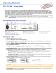
Rear Panel Features and Connections
1
2
100-240V ~ 0.3A MAX
3
6
5
4
INPUT
7
OUTPUT
AUDIO
3G/HD/SD-SDI
DVI-D
RGB / R-Y, Y, B-Y
L
LINK
BUFFERED LOOP-THROUGH
50/60 Hz
TX
R
RS-232
N/A
RX
Installation Steps
Tx Rx
a AC power connector
b Tx port (buffered
loop-through)
c Rx port
d Link LED
e DVI-D output connector
f RGB/YUV output
8
connector
g Audio output connector
h RS-232 connector
1.
Disconnect power from all equipment.
2.
(Optional) Mount the unit to a rack or furniture.
3.
Connect the video input. Connect an SD-SDI, HD-SDI, or 3G-SDI source to the SDI/HD-SDI (Rx) port of the fiber optic
LC input connector (c in the rear panel illustration above).
4.
Connect the video output. Connect a display or other output device to the DVD-D digital video connector (e) or to
the RGB/R-Y,Y,B-Y analog RGB (RGBHV, RGBS, and RGsB) or YUV component video connector (f).
5.
Connect a control device. Connect a host device such as a computer or touchpanel control system to one or both of
the following DVC ports to configure and control the DVC via Simple Instruction Set (SIS™) commands.
zz
zz
6.
RS-232 port (rear panel) — Connect a host device s to the Tx, Rx, and _ (ground) pins of this 5-pole captive
screw connector (h). The first and second pins of this connector are not used. The default protocol for this port is
9600 baud, 1 stop bit, no parity, 8 data bits, and no flow control.
Config port (front panel) — Connect a USB cable (USB A to USB mini B) between a USB port on your computer
and this port (a on the front panel illustration on the next page).
Connect the audio output. Connect an amplifier or other audio output device to the 5-pole captive screw audio
connector (g on the rear panel illustration), as shown below.
CAUTION:
R
R
Balanced Audio Output
Tip
Sleeves
Tip
L
L
Tip
Ring
Sleeves
Tip
Ring
Do not tin the wires!
Unbalanced Audio Output
For unbalanced audio, connect the sleeves to the ground contact. DO NOT connect them to negative (–)
contacts.
7.
(Optional) Daisy-chain additional FOX 3G devices. Connect another FOX 3G DVC or a FOX 3G HD-SDI to the
Buffered Loop-Through (Tx) port of the input connector (b). Up to three devices can be daisy-chained from this port.
8.
Connect power to the FOX 3G DVC by plugging a standard IEC power cord (provided) from a 100 to 240 VAC, 50-60 Hz
power source into the power receptacle (a).
1
Front Panel Features
2
1
3
4
5
MENU
ADJUST
NEXT
CONFIG
Extron
FOX 3G DVC
DIGITAL VIDEO CONVERTER
a
b
c
d
e
USB Config port
LCD screen
Menu button
Next button
Adjust knobs
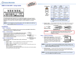
Configuring the FOX 3G DVC Using the Front Panel
Menu selections are displayed on the front panel LCD screen. To use any menu, press the Menu button repeatedly until the
desired menu is displayed (see the menu flow diagram at lower-right). Press the Next button repeatedly until the desired
submenu appears. Rotate an Adjust knob to select an item from a submenu. To return to the main menu at any time, press
Menu. After 30 seconds of inactivity, the screen displays the default cycle.
1.
From the Output Config submenus, use the Adjust knobs to select the output signal
type and the sync polarity to match the requirements of the display device.
2.
From the Advanced Config menu, Test Pattern submenu, select the Crop, Crosshatch,
Colorbars, and Grayscale test patterns to confirm that the settings of the display
device are correct.
NOTE:
3.
Default
Cycle
Menu
OUTPUT
CONFIG
Test pattern timings are based on the incoming SDI signals and are not
displayed if an active signal is not present.
Menu
Use the Audio Config submenus to configure the audio as desired.
AUDIO
CONFIG
Supported Input Resolutions
Supported
Resolutions
23.98 Hz 24 Hz 25 Hz 29.97 Hz 30 Hz 50 Hz 59.94 Hz 60 Hz
X
X
X
1080i
1080p
X
X
X
X
X
X
X
X
X
X
X
X
X
X
NTSC
X
PAL
NOTE:
30 sec.
Menu
Menu
720p
30 sec.
ADVANCED
CONFIG
30 sec.
Menu
EXIT MENU
PRESS NEXT
30 sec.
Next
X
The output resolution always matches the input resolution.
Simple Instruction Set (SIS) Commands
When setting up the FOX 3G DVC, you can issue SIS commands from your computer via RS-232 or USB as an alternative to
the front panel controls. See the FOX 3G DVC Series User Guide for a complete list of available SIS commands.
2
Command
ASCII command
(Host to Converter)
Response
(Converter to Host)
Additional Description
Mute video
1B
Vmt1]
Mute the video output.
Unmute video
0B
Vmt0 ]
Display the video output.
Mute audio
1Z
Amt1 ]
Mute the audio output.
Unmute audio
0Z
Amt0 ]
Unmute the audio output.
Enable lock (executive) mode
1X
Exe1]
Lock all front panel functions.
Disable lock mode
0X
Exe0 ]
Enable all front panel functions.
© 2011 Extron Electronics All rights reserved. www.extron.com
68-1518-51 Rev. C
09 11