1
OWNER’S MANUAL
RETAIN FOR FUTURE REFERENCE
TOLL FREE CUSTOMER SERVICE
1.888.800.1167
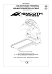
MODEL NUMBER: EVO 1CD
SERIAL NUMBER:
USER’S WEIGHT LIMITATION 350lbs.
APPLICATION STANDARD
ASSEMBLY
OPERATING INSTRUCTIONS
CONDITIONING GUIDELINES
MAINTENANCE
SERVICE
EVO 1CD Motorized Treadmill
Standard Equipment:
Optional Equipment:
BEFORE BEGINNING
precautions
For future service or related
questions.
Use the treadmill only as
described in this manual.
Please staple your receipt and/or
write in the name and phone number
of the retail store where you
purchased your EVO treadmill.
Place on a level surface, with 6
feet (2 m) of clearance behind it. Do
not place the treadmill on any surface
that blocks air openings. To protect
the floor or carpet from damage, place
a mat under the treadmill.
Name:
Phone Number:
Receipt:
Always examine your treadmill
before using to ensure all parts are
in working order.
Keep the treadmill indoors, away
from moisture and dust. Do not put
the treadmill in a garage or covered
patio, or near water.
Allow the belt to fully stop before
dismounting.
Keep children under the age of
12 and pets away from the treadmill
at all times.
WARNING: To reduce the risk of
burns, fire, electric shock, or injury
to persons, read the following
important precautions and
information before operating the
treadmill.
It is the responsibility of the owner
to ensure that all users of this
treadmill are adequately informed of
all warnings and precautions.
Always straddle the belt and allow
it to start moving before stepping
onto the belt.
When choosing a location for the
treadmill make sure that the location
and position permit access to a plug.
Do not operate the treadmill where
aerosol products are used or where
oxygen is being administered.
Precautions
When connecting the power
cord, plug the power cord into
a grounded circuit. No other
appliance should be on the same
circuit.
The treadmill should not be used
by persons weighing more than
350lbs.
Never allow more than one person
on the treadmill at a time.
Wear appropriate exercise clothing
when using the treadmill. Do not wear
loose clothing that could become
caught in the treadmill. Athletic support
clothes are recommended for both
men and women. Always wear
athletic shoes. Never use the treadmill
with bare feet, wearing only stockings,
or in sandals.
-2-
Never insert any object or body
parts into any opening.
Follow the safety information in
regards to plugging in your treadmill.
Keep the power cord away from
the incline wheels and do not run
the power cord underneath your
treadmill. Do not operate the
treadmill with a damaged or frayed
power cord.
Always unplug the treadmill before
cleaning and/or servicing. Service
to your treadmill should only be
performed by an authorized service
representative, unless authorized
and/or instructed by the
manufacturer. Failure to follow these
instructions will void the treadmill
warranty.
Never leave the treadmill
unattended while it is running.
POWER REQUIREMENTS
IMPROPER CONNECTION OF
THE EQUIPMENT GROUNDING
CONNECTOR CAN RESULT IN A
RISK OF AN ELECTRIC SHOCK.
CHECK WITH A QUALIFIED
ELECTRICIAN OR SERVICE MAN
IF YOU ARE IN DOUBT AS TO
WHETHER THE PRODUCT IS
PROPERLY GROUNDED. DO NOT
MODIFY THE PLUG PROVIDED
WITH THE PRODUCT, IF IT WILL
NOT FIT THE OUTLET, HAVE A
PROPER OUTLET INSTALLED BY
A QUALIFIED ELECTRICIAN.
This treadmill can be seriously
damaged by sudden voltage
changes in your home’s electrical
power. Voltage spikes, surges and
noise interference can result from
weather conditions or from other
appliances being turned on or off.
To reduce the possibility of treadmill
damage, always use a surge
protector (not included) with your
treadmill.
power requirements
Power Requirements:
conductor and a grounding plug.
Always plug the power cord into a
surge protector, and plug the surge
protector into an appropriate outlet
that is properly installed and
grounded in accordance with all local
codes and ordinances.
This product is for use on a nominal
120-volt circuit, and has a grounding
plug that looks like the plug illustrated
in the drawing below.
TREADMILL POWER CORD
SURGE PROTECTOR
GROUNDING PLUG
GROUNDING PIN
GROUNDING OUTLET
SURGE PROTECTOR
Surge protectors can be purchased
at most hardware stores. The
manufacturer recommends a single
outlet surge protector with a UL 1449
rating as a Transient Voltage Surge
Suppressor (TVSS) with a UL
suppressed voltage rating of 400V
or less and an electrical rating
120VAC,15 amps.
This treadmill must be grounded to
reduce the risk of electrical shock.
Grounding provides a path of least
resistance for electric current, should
the treadmill malfunction. This
treadmill comes with an electrical
cord having an equipment-grounding
ADAPTOR
SURGE PROTECTOR
GROUNDING PLUG
GROUNDING OUTLET
SCREW
-3-
BEFORE BEGINNING
preassembly
Open the boxes
Invite a friend
You are now ready to open the boxes
of your new equipment. Make sure
to inventory all of the parts that are
included in the boxes. Check the
Hardware Comparison Chart for a
full count of the number of parts
included for this product to be
assembled properly. If you are
missing any parts or have any
assembly questions call your local
Smooth Retailer.
Some of the assembly steps may
require heavy lifting. It is
recommended that you obtain the
assistance of another person when
assembling this product.
Gather your tools
Before starting the assembly of
your unit, make sure that you have
gathered all the necessary tools you
may require to assemble the unit
properly. Having all of the necessary
equipment at hand will save time
and make the assembly quick and
hassle-free.
User Weight Limitation
Please note that there is a weight
limitation for this product. If you
weigh more than 350lbs. it is not
recommended that you use this
product. Serious injury may occur
if the user’s weight exceeds the
limit shown here. This product is
not intended to support users whose
weight exceeds this limit.
Clear your work area
Make sure that you have cleared
away a large enough space to
properly assemble the unit. Make
sure space is free from anything that
may cause injury during assembly.
After the unit is fully assembled,
make sure there is a comfortable
amount of free area around the unit
for unobstructed operation.
-4-
Wrench
(1 piece)
Wrench
(1 piece)
40
Metal Cap
(2 pieces)
46
Bolt
M8 x 78mm
(2 pieces)
COMPARISON CHART
Wrench
(1 piece)
121
Screw
M8 x 19mm
(4 pieces)
0
10
8
Screw
M4 x 19mm
(4 pieces)
130
Screw
M6 x 15mm
(2 pieces)
20
30
40
16
Screw
M6 x 20mm
(2 pieces)
50
MILLIMETERS
-5-
4
Safety Key
(1 piece)
60
70
17
Screw
M8 x 15mm
(4 pieces)
80
90
100
55
Screw
#8 x 19mm
(4 pieces)
hardware
Allen Wrench
(1 piece)
For your convenience, we have
identified the hardware used in
the assembly of this product.
This chart is provided to help you
identify those items that may be
unfamiliar to you.
ASSEMBLY
assembly instructions
Step 1:
FIG-1
Remove your EVO 1CD Treadmill from
the carton and place it on the floor in an
open area as shown in FIG-1.
Raise the Right and Left Handle Uprights
(6 and 7) to the upright position and
secure with Screws (17).
-6-
ASSEMBLY
assembly instructions
Step 2:
Remove the Screw (51) then rotate the
Computer Support (3) up to the correct
position as shown and secure with the
Screw (51).
-7-
ASSEMBLY
assembly instructions
Step 3:
FIG-2
Rotate the Console (39) up to its proper
angle and secure with Screws (16) as
shown in FIG-2.
-8-
ASSEMBLY
assembly instructions
Step 4:
NOTE:
If you have the Optional Smooth Music Package
follow these instructions before attaching the
Console Tray (137).
Run the Cd Player Wires from the back of the
Console (39) first through the small hole on the
Console Tray (137), then through the tabs on the
back of the Console Tray (137) and finally through
the small hole on the side of the Console (39)
as shown.
Attach Console Tray Bracket (134) to the Console
Tray (137) and secure with Screws (135).
Attach the Console Tray (137). Insert the Console
Tray Bracket (134) into the Console (39) and
secure with the Screw (133).
NOTE: For proper use please make sure to
insert the plastic flange UNDER the metal tab
before inserting the screw.
Plastic Flange
CD PLAYER
WIRES
-9-
ASSEMBLY
assembly instructions
Step 5:
Attach the Cross Tube (45) to the Left and
Right Handle Uprights (6 and 7) and secure
with the Metal Cap (40) and Bolts (46).
Secure the Computer Support (3) to the
Right and Left Handle Uprights (6 and 7)
by tightening the Screws (18).
-10-
ASSEMBLY
assembly instructions
Step 6:
Unscrew Bolt (132). Insert the Console
Tray Support Tube (138) into the Cross
Tube (45) and secure with Bolt (132).
Do not fully tighten until later.
-11-
ASSEMBLY
assembly instructions
Step 7:
Rotate the Console Tray Support Tube
(138) and slide it into the hole
underneath the Console Tray (137).
-12-
ASSEMBLY
assembly instructions
Step 8:
Fully tighten Screws (18) and (51) and
Bolts (46) and (132) at this time.
-13-
ASSEMBLY
assembly instructions
Step 9:
Connect the Motion Control Sensor and Hand
Pulse Sensor wires then attach the Right and
Left Handlebars (30 and 12) to the Right and
Left Handle Uprights (6 and 7) and secure
using Screws (121).
Connect the
sensor wires
Connect the
sensor wires
Connect the sensor wires
-14-
ASSEMBLY
assembly instructions
Step 10:
Mount the Handle Cover Right - 1 (42) and the
Handle Cover Right - 2 (44) to the Right Handle
Upright (6) and secure with Screws (55) and (8).
Mount the Handle Cover Left - 1 (43) and the
Handle Cover Left - 2 (41) to the Left Handle
Upright (7) and secure with Screws (55) and (8).
-15-
ASSEMBLY
assembly instructions
Step 11:
Attach the Base Frame End Caps (14) to
the Left and Right Handle Upright (6 and 7)
and secure using the Screws (130).
-16-
OPTIONAL EQUIPMENT ASSEMBLY
When connecting the Speakers to the
Console first plug the Speaker Wires into
the sides of the Console. Then insert the
Speakers into the sides of the Console and
secure with Knobs.
assembly instructions
Speaker
Console
Connecting the Speakers and CD Player:
Speaker
Knob
Knob
Plug the two wires from the Console Tray
into the CD Player then place it on the Tray
as shown in FIG 3.
NOTE: There are three plugs located on
the left side of the CD player. The rear plug
is the AC power. The middle plug (Line
Out) is not used at all. Leave that one open.
The front plug is called Headphones Out
and is used for the speakers (or headphones
if you like).
Warning: On the right side of the CD Player
there is a button called “Hold”. This button
should ALWAYS be set to OFF. If it is on,
the unit will not play.
FIG-3
CD Player, right side
CD Player
Console Tray
CD Player, left side
AC Power
-17-
Headphones Out
Line Out (not used)
1. Stand behind the treadmill
and lift the deck up.
2. Raise the deck up until
CL
IC
K
FOLD UP FOR STORAGE
folding instructions
Your treadmill can be folded up for space
saving storage. To do this first be sure
that the deck is at the lowest incline
level. Simply lift the deck up from the
rear of the treadmill and fold up until it
locks in place. TO PREVENT INJURY
BE SURE YOU HAVE A FIRM HOLD
WHEN RAISING THE DECK. You will
hear a “click” sound as the lock engages.
the lock engages.
-18-
ROLL AWAY FOR STORAGE
roll away instructions
How to roll away the EVO 1CD Treadmill:
After folding the treadmill tilt it to one side (you
may need the help of a friend), reach under
the Base Frame (1) and pull down the Caster
Bracket (49). Repeat this procedure on the
other side. Then to roll away for storage simply
grab the handlebars and push as shown below.
NOTE: After moving the treadmill to the
desired location, make sure to put the Caster
Brackets (49) back into their upright position
in order to stabilize the treadmill for use.
Pull down to roll away.
Put up to stabilize for use.
-19-
UNFOLD FOR USE
unfolding instructions
To unfold the treadmill for use begin by
standing behind and supporting the deck
with your hands. Next release the lock
with your foot by stepping on the release
lever. TO PREVENT INJURY BE SURE
YOU HAVE A FIRM HOLD ON THE
DECK BEFORE RELEASING THE
LOCK. Slowly lower the deck until it
rests securely on the ground.
Release Lever
1. Support the deck and release
the lock with your foot.
2. Slowly lower the deck until it
rests securely on the ground.
-20-
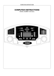
CONSOLE OPERATION
INCLINE / AGE
TIME / DISTANCE
PRESET
PROGRAMS
PRESET PROGRAMS
ENTER
INCLIN
E
START
STOP
SPEED
MESSAGE CENTER
SAFETY KEY
POWER ON
Set the POWER SWITCH, located on the base frame, to ON and insert the SAFETY KEY. All the LED lights
will auto scan.
SLEEP MODE
The computer will automatically enter SLEEP MODE if left idle for 5 minutes without any input in POWER ON
status. Press any button to return to POWER ON status when the computer is in the SLEEP MODE.
ENGLISH / METRIC CONVERSION
To switch the computer display information from English (miles, pounds, inches) to Metric, set the POWER
SWITCH, located on the base frame, to ON. Press and hold the ENTER button. Insert the SAFETY KEY. The
computer will sound one short BEEP, the English LED light will turn off and the Metric LED will light up. Repeat
the same procedure to switch between the Metric and English. Press the STOP button to confirm the change
and return to POWER ON status.
-21-
computer instructions
CALORIES / CALORIES PER HOUR
HEART RATE
CONSOLE OPERATION
computer instructions
COOL DOWN
For every program, there is a preset COOL DOWN feature at the end of each program. When the program is
complete, the speed will return to 2MPH/3.2KMH, the incline level will return to level 0 and the time will countdown
1 minute. After the timer 1 minute countdown is complete, the treadmill will stop and return to POWER ON status
after 30 seconds. If you wish to return to POWER ON status faster than 30 seconds, press the STOP button at
any time.
QUICK START
In POWER ON status, press the START button to QUICK START. The Speed starts from 0.5MPH/0.8KMPH and
the Incline Level starts from 0. Press the SPEED UP/DOWN buttons to change the Speed. Press the INCLINE
UP/DOWN buttons to change the incline level.
During the exercise press STOP to pause the program. The Speed and Incline Level return to the beginning
levels while the other information (Time, Distance, Calories) is paused. To recall values and resume exercising
press START. Pressing the STOP button again within 30 seconds returns all data to zero and the computer
returns to POWER ON status. If no buttons are pressed within 30 seconds the computer automatically returns
to POWER ON status and all data returns to zero.
GOAL COURSE TIME
When the computer is in POWER ON status press the
button on the console. The LED on
button will light
up. If no buttons are pressed after this within 3 minutes the program will return to POWER ON status. If you
wish to return to POWER ON status, press the STOP button any time.
The TIME LED will light up, show the preset time as 15:00 and blink. After press the
button. Press the
INCLINE UP/DOWN buttons to set your ideal workout time then press the START button to start. After pressing
the START button the TIME counts down from the preset time. The other information counts up until the treadmill
stops. The Speed starts from 2MPH/3.2KMPH and the incline starts from level 0. Press the SPEED UP/DOWN
buttons to adjust the speed. Press the INCLINE UP/DOWN buttons to adjust the incline level.
During exercise press STOP to pause the program. Speed and Incline Level return to the beginning levels while
the other information (Time, Distance, Calories) is paused. To recall values and resume exercising press START.
Pressing the STOP button again within 30 seconds returns all data to zero and the computer returns to POWER
ON status. If no buttons are pressed within 30 seconds the computer automatically returns to POWER ON status
and all data returns to zero.
GOAL COURSE DISTANCE
When the computer is in POWER ON status press the
button on the console. The LED on
button lights
up. If no buttons are pressed within 3 minutes the program will return to POWER ON status. If you wish to return
-22-
CONSOLE OPERATION
The DISTANCE LED will light up, show the preset distance as 3MI/5KM and begin blinking. After press the
button. Press the INCLINE UP/DOWN buttons to set up the ideal distance then press the START button to
start. After pressing the START button the DISTANCE counts down from the preset distance. The other
information counts up until the treadmill stops. The Speed starts from 2MPH/3.2KMPH and incline starts from
level 0. Press the SPEED UP/DOWN buttons to adjust the speed. Press the INCLINE UP/DOWN buttons to
adjust the incline level.
During exercise press STOP to pause the program. Speed and Incline Level return to the beginning levels while
the other information (Time, Distance, Calories) is paused. To recall values and resume exercising press START.
Pressing the STOP button again within 30 seconds returns all data to zero and the computer returns to POWER
ON status. If no buttons are pressed within 30 seconds the computer automatically returns to POWER ON status
and all data returns to zero.
GOAL COURSE CALORIES
When the computer is in POWER ON status press the
button on the console. The LED
button lights up.
If no buttons are pressed within 3 minutes the program will return to POWER ON status. If wish to return to
POWER ON status, press the STOP button any time.
The CALORIES LED will light up and show the preset calories burned as 050 and blinking. After press the
button. Press the INCLINE UP/DOWN buttons to set up the desired calories then press the START button
to start. After pressing the START button the CALORIES count down from the preset calories. The other
information counts up until the treadmill stops. The Speed starts from 2MPH/3.2KMPH and the incline starts
from level 0. Press the SPEED UP/DOWN buttons to adjust the speed. Press the INCLINE UP/DOWN buttons
to adjust the incline level.
During exercise press STOP to pause the program. The Speed and Incline Level return to the beginning levels
while the other information (Time, Distance, Calories) is paused. To recall values and resume exercising press
START. Pressing the STOP button again within 30 seconds returns all data to zero and the computer returns
to POWER ON status. If no buttons are pressed within 30 seconds the computer automatically returns to POWER
ON status and all data returns to zero.
20 MINUTE FAST RUN
When the computer is in POWER ON status press the
button on the console then press START to start the
program. If no buttons are pressed within 3 minutes the program will return to POWER ON status. At this time
the LED
button will light up. The Time counts down from 20:00. The other information will count up until
the treadmill stops. The SPEED and INCLINE level follow the preset program.
During exercise press STOP to pause the program. The Speed and Incline Level will return to the beginning
-23-
computer instructions
to POWER ON status, press the STOP button any time.
CONSOLE OPERATION
computer instructions
levels while the other information (Time, Distance, Calories) is paused. To recall values and resume exercising
press START. Pressing the STOP button again within 30 seconds returns all data to zero and the computer
returns to POWER ON status. If no buttons are pressed within 30 seconds the computer automatically returns
to POWER ON status and all data returns to zero.
During the exercise changes in both SPEED and INCLINE follow the preset program. You can still press the
SPEED UP/DOWN and INCLINE UP/DOWN to change the program. Any change only effects the current
workout period. The computer does not record any changes for future use on this program.
40 MINUTE JOG
When the computer is in POWER ON status press the
button on the console then press the START button
to start the program. If no buttons are pressed within 3 minutes the program will return to POWER ON status.
At this time the LED
button will light up. The TIME counts down from 40:00, and the other information will
count up until the treadmill stops. The SPEED and INCLINE levels follow the preset program.
During exercise press the STOP to pause the program. Speed and Incline Level return to the beginning levels
while the other information (Time, Distance, Calories) is paused. To recall values and resume exercising press
START. Pressing the STOP button again within 30 seconds returns all data to zero and the computer returns
to POWER ON status. If no buttons are pressed within 30 seconds the computer automatically returns to
POWER ON status and all data returns to zero.
During the exercise changes in both SPEED and INCLINE follow the preset program. You can still press the
SPEED UP/DOWN and INCLINE UP/DOWN to change the program. Any change only effects the current
workout period. The computer does not record any changes for future use on this program.
60 MINUTE WALK
When the computer is in POWER ON status press the
button on the console then press the START button
to start the program. If no buttons are pressed within 3 minutes the program will return to POWER ON status.
At this time the LED
button will light up. The TIME counts down from 60:00, and the other information will
count up until the treadmill stops. The SPEED and INCLINE level follow the preset program.
During exercise press STOP to pause the program. The Speed and Incline Level will return to the beginning
levels while the other information (Time, Distance, Calories) is paused. To recall values and resume exercising
press START. Pressing the STOP button again within 30 seconds returns all data to zero and the computer
returns to POWER ON status. If no buttons are pressed within 30 seconds the computer automatically returns
to POWER ON status and all data returns to zero.
During the exercise changes in both SPEED and INCLINE follow the preset program. You can still press the
SPEED UP/DOWN and INCLINE UP/DOWN to change the program. Any change only effects the current
workout period. The computer does not record any changes for future use on this program.
-24-
CONSOLE OPERATION
When the computer is in the POWER ON status, press the
button on the console.
USER AGE
SETUP:
USER AGE SET UP
The AGE LED will light up and show the preset age of 35. Press INCLINE UP/DOWN to set the user age then
press ENTER. If you do not press the INCLINE UP/DOWN button or do not press ENTER to confirm the age
within 30 seconds, the AGE LED will start blinking for 5 seconds in 30 second intervals to alert you. If you do
not want to continue this program, press the STOP button to return to the POWER ON status. When you press
the SPEED button to set the age, the heart rate LED will show the target heart rate along with the user age.
WORKOUT TIME
SETUP:
WORKOUT TIME SET UP
After the AGE SET UP procedure, the WORKOUT TIME SET UP procedure starts. The TIME LED will show
the preset time of 60:00. Press INCLINE UP/DOWN to set up the time. Press ENTER to confirm. If you do
not press the INCLINE UP/DOWN button or do not press ENTER to confirm the time within 30 seconds, the
TIME LED will start blinking for 5 seconds in 30 second intervals to alert you. If you do not want to continue
this program, press the STOP button to return to POWER ON status.
-25-
computer instructions
HEART RATE CONTROL
CONSOLE OPERATION
computer instructions
ACTIVATE HEART RATE CONTROL
After WORKOUT TIME SET UP, press the START button to activate the HEART RATE CONTROL program.
The Time will count down from the preset time and, the other information will count up until the treadmill stops.
The SPEED starts from 2MPH/3.2KM and the INCLINE starts from Level 0. The computer will sensor the actual
heart rate and adjust the incline level every minute. When the actual heart rate is lower than the standard (Preset)
heart rate, the incline will be elevated up one level. When the actual heart rate is maintained between the
standard heart rate and maximum heart rate, the incline level will not change. When the actual heart rate is over
the maximum heart rate, the incline level will be lowered one level.
During exercise press STOP to pause the program. The Speed and Incline Level will return to their beginning
levels while the other information (Time, Distance, Calories) is paused. To recall values and resume exercising
press START. Pressing the STOP button again within 30 seconds returns all data to zero and the computer
returns to POWER ON status. If no buttons are pressed within 30 seconds the computer automatically returns
to POWER ON status and all data returns to zero
-26-
CONSOLE OPERATION
computer instructions
MOTION CONTROL INSTRUCTION:
1. Press the
on and off:
switch on the console to switch the motion control function
When the LED light is ON the MOTION CONTROL is active.
When the LED light is OFF the MOTION CONTROL is off.
2. After switching on the MOTION CONTROL wave your right hand
approximately 6 inches above the motion sensor on the right handle bar to
increase the speed. The sensor will sound one short BEEP per scan and
speed up by 0.1 MPH per BEEP. Holding your right hand approximately 6
inches above the right sensor constantly results in the sensor sounding one
long BEEP per second and speeding up by 0.5 MPH per BEEP.
3. Wave you left hand approximately 6 inches above the motion sensor on
the left handle bar to decrease the speed. The sensor will sound one short
BEEP per scan and decrease speed by 0.1 MPH. Holding your left hand
approximately 6 inches above the left sensor constantly results in the sensor
sounding one long BEEP per second and decreasing speed by 0.5 MPH per
BEEP.
Use right senor to increase
speed.
4. Wave both hands approximately 6 inches above both motion sensors at
the same time. The sensor will sound two short BEEPs then stop the belt.
Always switch off the MOTION CONTROL function by pressing the
before turning off the power to the treadmill.
switch
Use left sensor to decrease
speed.
-27-
Use both sensors to stop
belt.
-28-
NOTES
notes
STABILIZER ADJUSTMENT
An uneven floor or improper stabilizer level can
cause the treadmill to wobble during use as
well as the incline adjustment to function
incorrectly. Please follow the procedure
described below to make sure the treadmill
stabilizer is adjusted correctly prior to use. You
may need the assistance of another person to
perform this adjustment.
1. To perform the stabilizer adjustment you
first need to bring the treadmill to the highest
incline level as shown in figure A. After you’ve
completed the assembly procedure plug in the
power cord and switch on the POWER
SWITCH. Insert the Safety Key and press the
START button to quick start the treadmill. Press
the INCLINE UP button until Level 12 shows
on the console. This is the highest incline level.
Now press the STOP button and pull out the
Safety Key. Switch off the POWER SWITCH
and unplug the power cord.
Bring the treadmill to the
highest incline level.
B
2. Inspect the four stabilizers (two per side)
located underneath the base frame. The
treadmill should sit on the floor with all 4
stabilizers resting firmly on the floor as shown
in figure B. Shake the handlebars back and
forth to check if they are resting firmly on the
floor. If they are not, pull the handlebar
backward to adjust the two front stabilizers and
push the handlebar forward to adjust the two
rear stabilizers as shown in figure C. Simply
turn the stabilizers like a screw to adjust their
heights. Repeat this until all 4 stabilizers sit
firmly on the floor.
Check to make sure the stabilizers
are resting firmly on the floor.
C
-29-
Pull the handlebar
backward or forward to
access the stabilizers.
stabilizer adjustment
A
Stabilizer adjustment instruction:
IMPORTANT STEPS
maintenance
How to Maintain the EVO 1CD
Treadmill:
Proper maintenance is very important
to ensure your treadmill is always in top
working condition. Improper
maintenance could cause damage or
shorten the life of your treadmill and
exceed the LIMITED WARRANTY
coverage.
2. If your belt tends to walk to the left,
rotate the left tension bolt clockwise 1/4
turn at a time, and follow with a test. If
the belt continues to walk to the left,
simply adjust the right tension bolt
counterclockwise.
3. If your belt appears to be loose, simply
tighten both bolts evenly 1/4 turn. If it
appears tight, simply loosen both bolts
evenly 1/4 turn.
IMPORTANT: Never use abrasives or
solvents to clean the treadmill. To
prevent damage to the computer, keep
liquids away and keep it out of direct
sunlight.
Inspect and tighten all parts of the
treadmill regularly. Replace any worn
parts immediately.
BELT ADJUSTMENT:
BELT ADJUSTMENT
The running belt has been adjusted
properly by the factory. However
transportation, uneven flooring or other
unpredicted reasons could cause the
belt to shift off center resulting in the
belt rubbing with the plastic side rail or
end caps and possibly causing damage.
To adjust the belt back to it’s proper
position please follow the directions
below:
Tension bolts for belt adjustment
1. If your belt tends to walk to the right,
rotate the right tension bolt clockwise.
We recommend adjustments of 1/4 turn
at a time, and follow with a test. If your
belt continues to walk to the right, simply
adjust the left belt tension bolt by turning
it 1/4 turn counterclockwise, follow with
a test.
-30-
MAINTENANCE INSTRUCTIONS
CLEANING:
Routine cleaning of your treadmill
will extend the product's life.
Warning! To prevent electrical
shock, be sure the power to the
treadmill is OFF and the unit
unplugged from the wall electrical
outlet before attempting any
cleaning or maintenance.
After each workout: Wipe off the
console and other treadmill
surfaces with a clean, water
dampened soft cloth to remove
excess perspiration.
IMPORTANT: Never use abrasives
or solvents to clean the treadmill.
To prevent damage to the
computer, keep liquids away and
keep it out of direct sunlight.
Weekly: Use of a treadmill mat is
recommended for ease of cleaning.
Dirt from your shoes contacts the
belt and eventually makes it to
underneath the treadmill. Vacuum
underneath treadmill once a week.
DECK LUBRICATION:
The walking belt has been prelubricated at the factory. However,
it is recommended that the walking
board be checked periodically for
lubrication to ensure optimal treadmill
performance. Your treadmill should
not have to be lubricated usually
within the first year or 500 hours of
use. Call your local Smooth dealer
for service or questions regarding
EVO products.
3. While lifting the side of the walking
belt, position the spray nozzle
between the walking belt and the
board approximately 6" from the front
of the treadmill. Apply the silicone
spray to the walking board, moving
from the front of the treadmill to the
rear. Repeat this on the other side
of the belt. Spray approximately 4
seconds on each side.
4. Allow the silicone to "set" for 1
minute before using the treadmill.
Every 30 days or 30 hours of
operation, lift the sides of the walking
belt and feel the top surface of the
walking board as far as you can
reach. If you feel signs of silicone,
no further lubrication is required. If
it feels dry to the touch, follow the
instructions below.
Please use Lube 'N Walk (can be
purchased from your dealer or call
the number on the front of the
manual), or a non-petroleum based
silicone such as "Napa 8300"
(available at most stores).
To apply lubricant to the walking
belt:
1. Position the walking belt so that
the seam is located on top and in
center of the walking board.
2. Insert the spray nozzle into the
spray head of the lubricant can.
-31-
SPRAY FROM
FRONT TO BACK
maintenance
WARNING! Before performing any
maintenance to your treadmill,
always unplug the power cord from
the surge protector.
WARRANTY
warranty
Warranty Coverage: Smooth Fitness, Inc. ("Smooth Fitness") warrants to the original purchaser that each new product to be free from
defects in workmanship and material, under normal use and conditions.
Period of Coverage: The Warranty on this product runs from the date of your purchase for a period of LIFETIME on the frame, TEN (10)
years on the motor, FIVE (5) years on the belt, deck and rollers, THREE (3) years on the electronics and ONE (1) year on labor. Smooth
Fitness reserves the right to inspect damaged parts for misuse.
It is recommended that the Original Receipt be kept with the product manual.
Remedy Provided by Smooth Fitness: Smooth Fitness will provide a replacement part free of charge if a defect is found during the Warranty
period. You must pay any charges for shipping and handling outside of the Continental United States and for labor. To obtain service call
your local Smooth Retailer.
Any redemption may be by repair or replacement of the affected parts and/or product at the sole discretion of Smooth Fitness,
by personnel approved by Smooth Fitness. If repairs are required, the unit will be repaired at the location of use or by return to the factory
as deemed appropriate by Smooth Fitness.
Parts repaired or replaced pursuant to this Warranty shall be warranted for the unexpired portion of the Warranty applying to the original
product. Any technical advice furnished before or after delivery in regard to the use or application of Smooth Fitness products is furnished
without charge and on the basis that it represents Smooth Fitness' best judgment under the circumstances but that the advice is used at
your sole risk.
Procedure for Obtaining Your Remedy Under This Warranty: To obtain service call your local Smooth Retailer. To help them assist you,
please have the following information ready:
Model name or number from the cover of the manual;
Serial number located on the frame of the unit; and
The part description and the order number.
Limitations on Warranty: This Warranty will only apply to the original end user. This Warranty does not cover any problems, damages or
failures that are caused by accident, improper assembly, failure to observe cautionary labels on the product, failure to operate the product
correctly, abuse or freight damage. Smooth Fitness does not warrant against any damage or defects that may result from repair or alterations
made to the product by an unauthorized repair facility.
This Warranty shall terminate if you sell or otherwise transfer this product. This Warranty does not apply to any product shipped or handled
outside of the United States or Canada. This Warranty does not apply if the product is used for rental or commercial use. Consequential
and incidental damages are not recoverable under this Warranty. (Some states do not allow the exclusion or limitation of incidental or
consequential damages, so the above limitation or exclusion may not apply to you.)
THIS WARRANTY IS EXPRESSLY IN LIEU OF ALL OTHER EXPRESS WARRANTIES. ALL IMPLIED WARRANTIES, INCLUDING
WARRANTIES OF MERCHANTABILITY OR FITNESS FOR ANY PARTICULAR PURPOSE, ARE LIMITED IN DURATION TO ONE (1)
YEAR FROM THE EFFECTIVE DATE OF THIS WARRANTY. SMOOTH FITNESS IS NOT LIABLE FOR CONSEQUENTIAL OR INCIDENTAL
DAMAGES RESULTING FROM ANY DEFECT IN PARTS NOR FOR ANY BREACH OF EXPRESS OR IMPLIED WARRANTIES. SMOOTH
FITNESS' SOLE LIABILITY UNDER THIS WARRANTY IS LIMITED TO THE TERMS DESCRIBED IN THIS FORM. THIS WARRANTY
GIVES YOU SPECIFIC LEGAL RIGHTS, AND YOU MAY ALSO HAVE OTHER RIGHTS WHICH VARY FROM STATE TO STATE.
For assistance with assembly or to order replacement parts, simply call your local Smooth Retailer. To help them assist you, please have
the following information ready:
Model name or number from the cover of the manual;
Serial number located on the frame of the unit; and
The part description and order number.
-32-
IMPORTANT STEPS
Before beginning
Before using this product, please
consult your personal physician for
a complete physical examination.
Frequent and strenuous exercise
should be approved by your doctor.
If any discomfort should result from
your use of this product, stop
exercising and consult your doctor.
Proper usage of this product is
essential. Please read your manual
carefully before exercising.
How you begin your exercise
program depends on your physical
condition. If you have been inactive
for several years, or are severely
overweight, you must start slowly
and increase your time gradually, a
few minutes per week.
Please keep all children away from
the equipment during use and when
equipment is unattended.
Always wear appropriate clothing,
including athletic shoes, when
exercising. Do not wear loose
clothing that could become caught
during exercising.
Make sure that all bolts and nuts are
tightened when equipment is in use.
Periodic maintenance is required on
all exercise equipment to keep it in
good condition.
Initially you may be able to exercise
only for a few minutes in your target
zone. However, your aerobic fitness
will improve over the next six to eight
weeks. Don’t be discouraged if it
takes longer. It’s important to work
at your own pace. Ultimately, you’ll
be able to exercise continuously for
30 minutes. And the better your
aerobic fitness, the harder you will
have to work to stay in your target
zone. But remember these
essentials:
>Contact your physician before
starting a workout or training
program. Have your doctor review
your training and diet programs to
advise you of a workout routine you
should adopt.
>Begin your training program slowly
with realistic goals that have been
set by you and your doctor.
>Supplement your program with
some type of aerobic exercise such
as walking, jogging, swimming,
dancing and/or bicycling.
-33-
Monitor your pulse frequently. If you
do not have an electronic heart rate
monitor, have your physician show
you the proper way to manually check
your pulse by using your wrist or
neck. Establish your target heart
rate based on your age and
condition.
>Drink plenty of fluids during the
course of your routine. You must
replace the water content lost from
excessive exercising to avoid
dehydration. Avoid drinking large
amounts of cold liquids. Fluids should
be at room temperature when
consumed.
important steps
Warning
To make sure your heart is beating
in its target zone, you’ll need to know
how to monitor your heart rate. The
easiest way is to feel the pulse in
the carotid artery on either side of
your neck, between the windpipe
and the large neck muscles. Count
PULSE IN BEATS PER MINUTE
EXERCISING IN YOUR TARGET ZONE
target heart rate
Finding your pulse
the number of beats in ten seconds,
then multiply by six. This gives you
the number of beats per minute.
How fast should your heart beat
during aerobic exercise? Fast
enough to reach and stay in its
“target zone,” a range of beats per
minute that is largely determined by
your age and physical condition. To
determine your target zone, consult
the chart we have provided.
ADVANCED•Sports, athletic conditioning or
interval training
200
190
FITNESS•Optimal training, aerobic
or cardiovascular
170
HEALTH•Beginner, low intensity with long
duration produces fat burning
180
160
150
140
130
120
110
100
90
80
70
20
25
30
35
40
45
50
55
60
65
70
AGE IN YEARS
Aerobic exercise is any
sustained activity that sends oxygen
to your muscles via your heart and
lungs. It will improve the fitness of
your lungs and heart: your body’s
most important muscle. Aerobic
fitness is promoted by any activity
that uses your large muscle groups
- arms, legs or buttocks, for example.
Your heart beats quickly and you
-34-
breath deeply. An aerobic exercise
should be part of your entire exercise
routine.
MUSCLE CHART
muscle chart
The exercise routine that is
performed on this product
will develop lower body
muscle groups. These
muscle groups are shown
on the chart below.
Trapezius
Anterior Deltoid
Posterior Deltoid
Pectoralis Major
Serratus Anterior
Triceps
Bicep
Latissimus Dorsi
Abdominals
Sartorius
Gluteals
Quadriceps
Hamstrings
Tibialis
Gastrocnemius
(Calf)
-35-
WARM UP AND COOL DOWN
stretching routine
Inner Thigh Stretch
A successful exercise program
consists of a warm-up, aerobic
exercise, and a cool-down. Do the
entire program at least two and
preferably three times a week, resting
for a day between workouts. After
several months, you can increase
your workouts to four or five times
per week.
Warming up is an important part of
your workout, and should begin every
session. It prepares your body for
more strenuous exercise by heating
up and stretching out your muscles,
increasing your circulation and pulse
rate, and delivering more oxygen to
your muscles. At the end of your
workout, repeat these exercises to
reduce sore muscle problems. We
suggest the following warm-up and
cool-down exercises:
Sit with the soles of your feet together
with your knees pointing outward. Pull
your feet as close into your groin as
possible. Gently push your knees
towards the floor. Hold for 15 counts.
Hamstring Stretch
Sit with your right leg extended. Rest the
sole of your left foot against your right inner
thigh. Stretch toward your toe as far as
possible. Hold for 15 counts. Relax and
then repeat with left leg extended.
Head Roll
Rotate your head to the right for one count,
feeling the stretch up the left side of your
neck. Next, rotate your head back for one
count, stretching your chin to the ceiling
and letting your mouth open. Rotate your
head to the left for one count, and finally,
drop your head to your chest for one count.
-36-
Calf-Achilles Stretch
Lean against a wall with your left leg in
front of the right and your arms forward.
Keep your right leg straight and the left
foot on the floor; then bend the left leg
and lean forward by moving your hips
toward the wall. Hold, then repeat on
the other side for 15 counts.
Side Stretch
Open your arms to the side and continue
lifting them until they are over your head.
Reach your right arm as far upward
toward the ceiling as you can for one
count. Feel the stretch up your right side.
Repeat this action with your left arm.
-37-
Toe Touch
Slowly bend forward from
your waist, letting your back
and shoulders relax as you
stretch toward your toes.
Reach down as far as you can
and hold for 15 counts.
stretching routine
Shoulder Lift
Lift your right shoulder up toward
your ear for one count. Then
lift your left shoulder up for one
count as you lower your right
shoulder.
A MAJORITY OF THE LISTED HARDWARE IS ALREADY IN PLACE
parts list
NUMBER
DESCRIPTION
QUANTITY
ORDER NUMBER
01
02
03
04
05
06
07
08
09
10
11
12
13
14
15
16
17
18
19
20
21
22
23
24
25
26
27
28
29
30
31
32
33
34
35
36
37
38
39
40
41
42
43
44
45
46
Base Frame
3*12 Screw
Computer Support
Safety Key
Plastic Ring
Right Handle Upright
Left Handle Upright
4*19 Screw
6*13 Washer
Motion Control
End Cap
Left Handlebar
M6 Nut
Base Frame End Cap
11*6 Washer
M6*15 Screw
M8*15 Screw
M8*25 Screw
M6*55 Screw
M5*8 Screw
Power Switch
M14*54 Screw
M10 Nylon Nut
Base Frame End Cap-Left
Base Frame End Cap-Left-1
Base Frame End Cap-Right-1
Base Frame End Cap-Right
8*43 Screw
M14 Nut
Right Handlebar
Topple Bolt
Cushion
Bushing
Wheel Shaft
Lock Washer
Right Side Strip
Spring
16*8 Washer
Console
Metal Cap
Handle Cover-Left-1
Handle Cover-Right-1
Handle Cover-Left-2
Handle Cover-Right-2
Cross Tube
M8*78 Bolt
1
4
1
1
1
1
1
20
2
2
2
1
2
2
2
2
4
13
2
2
1
2
3
1
1
1
1
1
2
1
4
4
6
2
2
1
1
1
1
2
1
1
1
1
1
2
EVO1CD-01
EVO1CD-02
EVO1CD-03
EVO1CD-04
EVO1CD-05
EVO1CD-06
EVO1CD-07
EVO1CD-08
EVO1CD-09
EVO1CD-10
EVO1CD-11
EVO1CD-12
EVO1CD-13
EVO1CD-14
EVO1CD-15
EVO1CD-16
EVO1CD-17
EVO1CD-18
EVO1CD-19
EVO1CD-20
EVO1CD-21
EVO1CD-22
EVO1CD-23
EVO1CD-24
EVO1CD-25
EVO1CD-26
EVO1CD-27
EVO1CD-28
EVO1CD-29
EVO1CD-30
EVO1CD-31
EVO1CD-32
EVO1CD-33
EVO1CD-34
EVO1CD-35
EVO1CD-36
EVO1CD-37
EVO1CD-38
EVO1CD-39
EVO1CD-40
EVO1CD-41
EVO1CD-42
EVO1CD-43
EVO1CD-44
EVO1CD-45
EVO1CD-46
-38-
A MAJORITY OF THE LISTED HARDWARE IS ALREADY IN PLACE
DESCRIPTION
QUANTITY
ORDER NUMBER
47
48
49
50
51
52
53
54
55
56
57
58
59
60
61
62
63
64
65
66
67
68
69
70
71
72
73
74
75
76
77
78
79
80
81
82
83
84
85
86
87
88
89
90
91
92
M8 Nylon Nut
Foot Up Lock
Caster Bracket
Caster
M5*10 Screw
4*10 Screw
Motor Hood-Top
Left Side Strip
8*15 Screw
Rear End Cap
M5*12 Screw
M10*30 Screw
Spring Bracket (S)
Running Board
M10*35 Screw
Tube Clamp
Gear Sleeve
Bumper
U Bracket
M16*54 Screw
Bumper
35*18 Washer
M16 Nut
Elevation Motor
22*8 Washer
Bumper
M8*15 Screw
M10*120 Screw
14*10*18.5 Bushing
M10*63 Screw
Cushion
M8*89 Bolt
M10*136 Screw
Motor
Motor Holder
Motor Belt
Front Roller Shaft
Front Roller
Control Board
Shock
Transfer Board
Cushion
Rear Roller
Rear Roller Shaft
M10 Screw
15*8 Washer
2
1
2
2
1
14
1
1
34
1
2
8
2
1
1
2
1
1
1
1
1
1
1
1
2
1
2
1
2
1
2
1
1
1
1
1
1
1
1
1
1
10
1
1
15
10
EVO1CD-47
EVO1CD-48
EVO1CD-49
EVO1CD-50
EVO1CD-51
EVO1CD-52
EVO1CD-53
EVO1CD-54
EVO1CD-55
EVO1CD-56
EVO1CD-57
EVO1CD-58
EVO1CD-59
EVO1CD-60
EVO1CD-61
EVO1CD-62
EVO1CD-63
EVO1CD-64
EVO1CD-65
EVO1CD-66
EVO1CD-67
EVO1CD-68
EVO1CD-69
EVO1CD-70
EVO1CD-71
EVO1CD-72
EVO1CD-73
EVO1CD-74
EVO1CD-75
EVO1CD-76
EVO1CD-77
EVO1CD-78
EVO1CD-79
EVO1CD-80
EVO1CD-81
EVO1CD-82
EVO1CD-83
EVO1CD-84
EVO1CD-85
EVO1CD-86
EVO1CD-87
EVO1CD-88
EVO1CD-89
EVO1CD-90
EVO1CD-91
EVO1CD-92
-39-
parts diagram
NUMBER
A MAJORITY OF THE LISTED HARDWARE IS ALREADY IN PLACE
parts list
NUMBER
DESCRIPTION
QUANTITY
ORDER NUMBER
93
94
95
96
97
98
99
100
101
102
103
104
105
106
107
108
109
110
111
112
113
114
115
116
117
118
119
120
121
122
123
124
125
126
127
128
13*6.5 Washer
M6*45 Screw
Spring Bracket
M8*30 Screw
Metal Plate
Roller
Frame
Bushing
Plastic Clamp-Top
Plastic Clamp-Bottom
Plastic Cap
Lever Arm Cap-Front
Lever Arm Cap-Rear Left
Lever Arm Cap-Rear Right
Elevation Frame
Motor Cover Bottom
Pivot Shaft
10MM Lock Washer
3/8"*30 Screw
Bearing
22*10 Washer
Support
Pivot Shaft
14*10*8 Bushing
Motor Hood-Bottom
M8*43 Screw
M6*70 Screw
M5*8 Screw
M8*19 Screw
Running Belt
Micro Switch
M3*8 Screw
Screw
Speaker Holder
Speaker Holder Cap
Cap
3
2
2
4
2
2
1
4
2
2
2
2
1
1
1
1
1
2
2
2
2
1
1
2
1
2
1
4
4
1
1
2
1
4
4
2
EVO1CD-93
EVO1CD-94
EVO1CD-95
EVO1CD-96
EVO1CD-97
EVO1CD-98
EVO1CD-99
EVO1CD-100
EVO1CD-101
EVO1CD-102
EVO1CD-103
EVO1CD-104
EVO1CD-105
EVO1CD-106
EVO1CD-107
EVO1CD-108
EVO1CD-109
EVO1CD-110
EVO1CD-111
EVO1CD-112
EVO1CD-113
EVO1CD-114
EVO1CD-115
EVO1CD-116
EVO1CD-117
EVO1CD-118
EVO1CD-119
EVO1CD-120
EVO1CD-121
EVO1CD-122
EVO1CD-123
EVO1CD-124
EVO1CD-125
EVO1CD-126
EVO1CD-127
EVO1CD-128
130
131
132
133
134
135
136
137
138
M6*20 Screw
M10 Nylon Nut
M8*25 Bolt
M5*10 Screw
Console Tray Bracket
M8*10 Screw
Cover
Console Tray
Console Tray Support Tube
2
1
1
1
1
3
1
1
1
EVO1CD-130
EVO1CD-131
EVO1CD-132
EVO1CD-133
EVO1CD-134
EVO1CD-135
EVO1CD-136
EVO1CD-137
EVO1CD-138
-40-
MANY PARTS SHOWN HAVE BEEN PRE-ASSEMBLED BY THE FACTORY
parts diagram
-41-
-42-
A MAJORITY OF THE LISTED HARDWARE IS ALREADY IN PLACE
parts diagram
MANY PARTS SHOWN HAVE BEEN PRE-ASSEMBLED BY THE FACTORY
parts diagram
-43-
Smooth Fitness
717 Fellowship Road
Suite C
Mt. Laurel, NJ 08054
1.888.800.1167
Copyright © 2002