1
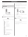
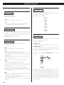
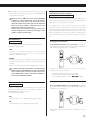
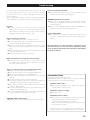
D01141820A
I-03
Integrated Amplifier
OWNER’S MANUAL
CAUTION: TO REDUCE THE RISK OF ELECTRIC SHOCK, DO NOT
REMOVE COVER (OR BACK). NO USER-SERVICEABLE PARTS
INSIDE. REFER SERVICING TO QUALIFIED SERVICE PERSONNEL.
The lightning flash with arrowhead symbol, within an
equilateral triangle, is intended to alert the user to the
presence of uninsulated “dangerous voltage” within the
product’s enclosure that may be of sufficient magnitude
to constitute a risk of electric shock to persons.
The exclamation point within an equilateral triangle is
intended to alert the user to the presence of important
operating and maintenance (servicing) instructions in the
literature accompanying the appliance.
IMPORTANT SAFETY INSTRUCTIONS
1) Read these instructions.
2) Keep these instructions.
3) Heed all warnings.
4) Follow all instructions.
5) Do not use this apparatus near water.
6) Clean only with dry cloth.
7) Do not block any ventilation openings. Install in accordance with
the manufacturer’s instructions.
8) Do not install near any heat sources such as radiators, heat
registers, stoves, or other apparatus (including amplifiers) that
produce heat.
9) Do not defeat the safety purpose of the polarized or groundingtype plug. A polarized plug has two blades with one wider than
the other. A grounding type plug has two blades and a third
grounding prong. The wide blade or the third prong are provided
for your safety. If the provided plug does not fit into your outlet,
consult an electrician for replacement of the obsolete outlet.
10)Protect the power cord from being walked on or pinched
particularly at plugs, convenience receptacles, and the point
where they exit from the apparatus.
11) Only use attachments/accessories specified by the manufacturer.
12)Use only with the cart, stand, tripod, bracket, or
table specified by the manufacturer, or sold with
the apparatus. When a cart is used, use caution
when moving the cart/apparatus combination to
avoid injury from tip-over.
13)Unplug this apparatus during lightning storms or when unused
for long periods of time.
14)Refer all servicing to qualified service personnel. Servicing is
required when the apparatus has been damaged in any way, such
as power-supply cord or plug is damaged, liquid has been spilled
or objects have fallen into the apparatus, the apparatus has been
exposed to rain or moisture, does not operate normally, or has
been dropped.
2
o Do not expose this apparatus to drips or splashes.
o Do not place any objects filled with liquids, such as vases, on the
apparatus.
o Do not install this apparatus in a confined space such as a book
case or similar unit.
o The apparatus draws nominal non-operating power from the
AC outlet with its POWER or STANDBY/ON switch not in the ON
position.
o The apparatus should be located close enough to the AC outlet so
that you can easily grasp the power cord plug at any time.
o The mains plug is used as the disconnect device, the disconnect
device shall remain readily operable.
o Products with Class © construction are equipped with a power
supply cord that has a 3-prong grounding plug. The cord of such
a product must be plugged into an AC outlet that has a protective
grounding connection.
o If the product uses batteries (including a battery pack or installed
batteries), they should not be exposed to sunshine, fire or excessive
heat.
o Caution should be taken when using earphones or headphones
with the product because excessive sound pressure (volume) from
earphones or headphones can cause hearing loss.
WARNING: TO PREVENT FIRE OR SHOCK HAZARD,
DO NOT EXPOSE THIS APPLIANCE TO RAIN OR
MOISTURE.
CAUTION
o DO NOT REMOVE THE EXTERNAL CASES OR CABINETS TO EXPOSE
THE ELECTRONICS. NO USER SERVICEABLE PARTS ARE WITHIN.
o IF YOU ARE EXPERIENCING PROBLEMS WITH THIS PRODUCT,
CONTACT ESOTERIC FOR A SERVICE REFERRAL. DO NOT USE THE
PRODUCT UNTIL IT HAS BEEN REPAIRED.
For U.S.A.
This equipment has been tested and found to comply with the
limits for a Class B digital device, pursuant to Part 15 of the FCC
Rules. These limits are designed to provide reasonable protection
against harmful interference in a residential installation. This
equipment generates, uses, and can radiate radio frequency energy
and, if not installed and used in accordance with the instructions,
may cause harmful interference to radio communications. However,
there is no guarantee that interference will not occur in a particular
installation. If this equipment does cause harmful interference to
radio or television reception, which can be determined by turning
the equipment off and on, the user is encouraged to try to correct
the interference by one or more of the following measures:
• Reorient or relocate the equipment and/or the receiving
antenna.
• Increase the separation between the equipment and receiver.
• Connect the equipment into an outlet on a circuit different
from that to which the receiver is connected.
• Consult the dealer or an experienced radio/TV technician for
help.
CAUTION
Changes or modifications to this equipment not expressly
approved by TEAC CORPORATION for compliance will void the
user’s warranty.
Contents
Thank you for choosing ESOTERIC. Read this manual carefully
to get the best performance from this unit.
What’s in the box. . . . . . . . . . . . . . . . . . . . . . . . . . . . . . . . . . . . . . . . . . . . . . . . . . . . . 3
What’s in the box
What’s in the box
Check to be sure the box includes all the supplied accessories shown
below.
Please contact the store where you purchased this unit if any of these
accessories are missing or have been damaged during transportation.
Before Use. . . . . . . . . . . . . . . . . . . . . . . . . . . . . . . . . . . . . . . . . . . . . . . . . . . . . . . . . . . . 4
Identifying the Parts (Main Unit). . . . . . . . . . . . . . . . . . . . . . . . . . . . . . . . . . . . . . 5
Remote control unit (RC-1251) x 1
Identifying the Parts (Remote Control Unit). . . . . . . . . . . . . . . . . . . . . . . . . . . 6
Remote Control Unit. . . . . . . . . . . . . . . . . . . . . . . . . . . . . . . . . . . . . . . . . . . . . . . . . . 7
Connections. . . . . . . . . . . . . . . . . . . . . . . . . . . . . . . . . . . . . . . . . . . . . . . . . . . . . . . . . . 8
Speaker Connections. . . . . . . . . . . . . . . . . . . . . . . . . . . . . . . . . . . . . . . . . . . . . . . 10
Connections When Using as a Pre Amplifier. . . . . . . . . . . . . . . . . . . . . . . . . . 11
Batteries (AA, R6 or SUM-3) x 2
Basic Operation. . . . . . . . . . . . . . . . . . . . . . . . . . . . . . . . . . . . . . . . . . . . . . . . . . . . . . 12
Dimmer/Muting. . . . . . . . . . . . . . . . . . . . . . . . . . . . . . . . . . . . . . . . . . . . . . . . . . . . . 13
Power cord x 1
Balance and Input Level Settings. . . . . . . . . . . . . . . . . . . . . . . . . . . . . . . . . . . . 14
Additional Settings. . . . . . . . . . . . . . . . . . . . . . . . . . . . . . . . . . . . . . . . . . . . . . . . . . 15
Troubleshooting. . . . . . . . . . . . . . . . . . . . . . . . . . . . . . . . . . . . . . . . . . . . . . . . . . . . . 19
Specifications . . . . . . . . . . . . . . . . . . . . . . . . . . . . . . . . . . . . . . . . . . . . . . . . . . . . . . 20
Rear Panel Layout . . . . . . . . . . . . . . . . . . . . . . . . . . . . . . . . . . . . . . . . . . . . . . . . . . 21
Felt pads x 3
o To protect the supporting furniture surface, you may stick the
felt pads to the bottom of the feet.
Owner’s manual (this document) x 1
o Keep this manual for future reference.
Warranty card x 1
3
Before Use
Read this before attempting any operations.
CAUTION
o Do not place any objects on this unit.
Placement of the unit
This unit is heavy. Take care to prevent injuries when lifting and
installing it.
o High-quality tool steel is used for the spike feet, securely attached
to the bottom of the unit. Although the outer feet may appear
loose, the weight of the unit causes them to become firm and
secure. The design effectively damps and reduces vibration.
Spike foot
Bottom plate
of the unit
Protection foot
o The voltage supplied to the unit should match the voltage as
printed on the rear panel. If you are in any doubt regarding this
matter, consult an electrician.
o Do not open the cabinet as this might result in damage to the
circuitry or cause electric shock. If a foreign object should get into
the unit, contact your dealer or service company.
o When removing the power plug from the wall outlet, always pull
directly on the plug, never yank on the cord.
Retaining screws
To protect the supporting furniture surface, you may stick the
supplied felt pads to the bottom of the protection feet.
o Place the unit in a stable location near the audio system that you
will use.
o Choose the installation location of your unit carefully. Avoid placing
it in direct sunlight or close to a source of heat. Also avoid locations
subject to vibrations and excessive dust, heat, cold or moisture.
o As the unit may become warm during operation, always leave
sufficient space around the unit for ventilation.
Make sure there is at least 8” (20 cm) of space above and at least 2”
(5 cm) of space on each side of the unit.
When you install the unit in a rack, use one which has ventlations
and take care of temperature of the unit.
o Do not place this unit on a thick carpet.
o When the unit is turned on, switching on the TV may cause lines
to appear on the TV screen, depending on the condition of the
electric waves of the TV broadcast. This is not malfunction in the
unit or the TV. If you see such lines, keep this unit well away from
the TV set.
4
o Do not cover this unit with a cloth.
Maintenance
If the surface of the unit gets dirty, wipe it with a soft cloth or
use diluted mild liquid soap. Allow the surface of the unit to dry
completely before using.
For safety, disconnect the power cord from the socket before
cleaning.
o Never spray liquid directly on this unit.
o Do not use thinner or alcohol as they could damage the surface of
the unit.
o Avoid allowing rubber or plastic materials to touch this product for
long periods of time. It could damage the cabinet.
Identifying the Parts (Main Unit)
A
B
C
A INPUT
Turn this knob to select a source. Select the terminal that is
connected to the device you want to play (page 12).
In setup mode, turn this knob to change the setting of each item
(pages 14, 15).
o You can assign names to the input terminals. You can also set
the terminals to be skipped when you do not want to use them
(pages 17, 18).
D E
F
E PHONES
For private listening, insert a 6.35 mm (1/4”) stereo headphone
plug into this jack, and then adjust the volume by turning the
VOLUME knob.
TO AVOID DAMAGING YOUR HEARING
Do not connect headphones to the PHONES jack while
wearing them. Moreover, do not disconnect headphones or
turn the unit on or off while wearing them.
Very loud sounds could be output from the headphones if
volume is not turned down prior to plugging on or prior to
unplugging. It may cause damage to your hearing.
B POWER
Press this button to turn the unit on and off.
The blue indicator lights when the unit is turned on.
Turn the volume to a minimum level before you turn
the unit on or off. Failure to do so may cause sudden
loud noises and hearing damage when you turn on the
unit next time.
o Turn off the power when not using this unit.
C Display
Displays the current input terminal names, volume, setting items
etc.
D Remote sensor
When operating the remote control unit, point it towards this
area on the front panel.
F VOLUME
Tur n this k n o b cl o ck w is e to in creas e vo lum e an d
counterclockwise to reduce the volume.
o When the volume value exceeds the maximum total gain value
of this unit, the volume display blinks. Lower the volume until the
display stops blinking.
o When you set the RCA2 terminals to “THRU”, the VOLUME knob
does not work on RCA2 signal inputs (page 16).
o When you set the PRE OUT terminals to “REC”, the VOLUME knob
does not work on this output. In this setting the unit sends a fixed
output level for recording (page 16).
A sudden loud noise heard over the speakers may damage
your hearing or the speakers. Turn the volume to a minimum
level before you begin playback of source devices. Then
gradually increase the volume as desired.
5
Identifying the Parts (Remote Control Unit)
The buttons not mentioned in this chapter do not work with the I-03.
However, they can be used for other Esoteric products.
a ON (confirm settings)
Some settings can be changed using this button in “Additional
settings” (pages 16, 18).
You can also assign names to the terminals using this button
(page 18).
a
o You can not turn the power on or off using this button.
b INPUT (</>)
e
Press these buttons to select a source. Select the input terminal
that is connected to the device that you want to play (page 12).
In setup mode, press these buttons to change the setting of each
item (pages 14, 15).
c DIMMER
Use this button to select one of four brightness levels for the
display and indicator lamps (page 13).
d SETUP
b
f
c
d
Press this button to enter the setup mode for balance and output
level adjustments (page 14).
Press this button for more than 2 seconds to enter additional
setup modes (page 15).
g
e CLEAR
In setup mode, use this button to exit the setup mode (pages 14,
15).
f VOLUME (+/−)
Use these buttons to adjust the volume.
o When you set the RCA2 terminals to “THRU” (page 16), or when
you set the PRE OUT terminals to “REC” (page 16), the VOLUME
control buttons do not work.
g MUTING
Press this button to mute the sound. Press this button again to
restore the sound (page 13).
To simplify explanations, instructions in this manual might refer to
the main unit or remote control unit only. In such cases, the same
controls on the remote control and main unit will operate similarly.
6
Remote Control Unit
The included remote control allows this unit to be operated from a
distance.
Point the remote control unit at the main unit’s remote sensor
within 23 feet (7 m) of the main unit.
Remote sensor
7 m
(23 feet)
Battery Replacement
If the operating range between the remote control unit and main
unit decreases, the batteries are exhausted. In this case replace the
batteries with new ones.
For more information about collection of batteries, please contact
your local municipality, your waste disposal service or the point of sale
where you purchased the items.
Precautions concerning batteries
Misuse of batteries could cause them to rupture or leak leading
to fire, injury or the staining of nearby things. Please read and
observe the following precautions carefully.
o Be sure to insert the batteries with correct positive (¥) and
negative (^) orientations.
o Use batteries of the same type. Never use different types of
batteries together.
o Depending on the angle, reception might be difficult. Use the
remote control from directly in front of the unit as much as
possible.
o Even if the remote control unit is used within its effective range,
operation by remote control might be impossible if there are any
obstacles between the unit and the remote control.
o If direct sunlight or strong artificial illumination shines on the
remote sensor, the remote control might not function.
o If the remote control unit is operated near other devices that
generate infrared rays, or if other remote controls that use infrared
rays are operated near the unit, this unit might operate incorrectly.
The other devices might also operate incorrectly.
o Both rechargeable and non-rechargeable batteries can be used.
Refer to the precautions on their labels.
o If the remote control will not be used for a long time (more than a
month), remove the batteries to prevent them from leaking.
o If the batteries leak, wipe away the leakage inside the battery
compartment and replace the batteries with new ones.
o Do not use batteries of types other than those specified. Do not
mix new batteries with old ones or use different types of batteries
together.
o Do not heat or disassemble batteries. Never throw batteries into
fire or water.
o Do not carry or store batteries with other metallic objects. The
batteries could short circuit, leak or explode.
Battery Installation
o Never recharge a battery unless it is confirmed to be a
rechargeable type.
Use a Philips screwdriver to remove the cover from the bottom of
the remote control, and slowly pull out the battery case. Insert two
AA batteries in the correct ¥/^ orientations, reinsert the case
and close the cover.
7
Connections
After all other connections are complete, connect the power cord plug to the AC wall socket.
o Read the instructions of each component you intend to use with this unit.
o Be sure to connect each plug securely. To prevent hum and noise, do not bundle the connection cords.
Turntable
Recorder etc.
AUDIO IN
R L
RCA audio cable
XLR pin assignment
1. COMMON
2. HOT (+)
3. COLD (−)
A
B
C
D
Super Audio CD Player
etc.
8
Power cord
R
L
AUDIO OUT
RCA audio cable
XLR cable
A
R
L
AUDIO OUT
Super Audio CD Player/
Tuner etc.
Wall socket
A Analog audio input terminals [INPUTS]
C Analog audio output terminals [PRE OUT]
Inputs analog 2-channel audio signals.
Connect these terminals to Super Audio CD players, tuner, etc.
using commercially available XLR or RCA audio cables.
Outputs analog 2-channel audio signals.
Connect these terminals to recorder, etc. using commercially
available RCA audio cables.
Connect the R terminal on this unit to the right (R) terminal of the
input source device and the L terminal on this unit to the left (L)
terminal of the input source device.
o You can also connect this unit directly to a power amplifier. This
option allows you to use this unit as a pre amplifier, see page 11
“Connections When Using as a Pre Amplifier)”.
XLR1/2 terminals
Use balanced XLR audio cables.
Push in the XLR plug until the lever clicks. To remove the XLR
plug, hold down the lever and pull it out.
o When connecting to a recorder, set the Pre out setting to “REC”
(page 16).
RCA1/2/3/PHONO terminals
Use RCA audio cables.
D Power cord receptacle
Connect the power cord to the power cord receptacle.
After all other connections are complete, connect the power
cord plug to the AC wall socket.
Make sure to connect:
White plug e White jack (L: left channel)
Red plug e Red jack (R: right channel)
Do not use any power cords other than the one included
with this unit or a power cord specified by ESOTERIC. Use of
other power cords may result in fire or cause electric shock.
RCA2/PHONO terminal
You can select whether to use the RCA2 terminals as input
terminals or as signal through terminals (page 16).
When a front speaker is used together with an AV amplifier,
connecting the RCA2 terminals to the FRONT L/R of the AV
amplifier’s pre out terminal and setting RCA2 to “THRU” (signal
through terminals) will allow the front speaker to be used as a
front speaker for the AV amplifier. By this means, the volume
of the front speaker can then be controlled with the AV
amplifier’s volume control.
RCA3/PHONO terminal
You can also connect a turntable to this terminal.
When connecting to a turntable, set the RCA3 setting to
“PHONO” (page 17).
o Connect the ground lead of the turntable to the GND
terminal [SIGNAL GND] terminal of the I-03.
ESOTERIC uses ESOTERIC MEXCEL stress-free cable as a
reference. The following items are available in the ESOTERIC
MEXCEL cable series.
RCA audio cable
XLR audio cable
RCA digital cable
XLR digital cable
BNC digital cable
Speaker cable
Power cable
B GND terminal [SIGNAL GND]
Connection of this terminal with the ground terminal of another
chassis may improve sound quality.
o Note that this is NOT an electrical safety ground (earth).
o When a turntable is connected to the RCA3/PHONO terminal,
make sure to connect the ground lead of the turntable to this
terminal.
9
Speaker Connections
After all other connections are complete, connect the power cord plug to the AC wall socket.
o Read the instructions of each component you intend to use with this unit.
o The metal portions of the two separate wires should not touch or an electrical short can occur. Shorted wires can
create a fire hazard or induce a failure in your equipment.
o Be sure to connect each plug securely. To prevent hum and noise, do not bundle the speaker cables together with the
power cord.
Left speaker
Right speaker
Speaker cables
Connect the speakers to the SPEAKER terminals using commercially
available speaker cables.
How to connect
Connect the left channel of the SPEAKER terminals to the left speaker,
and the right channel of the SPEAKER terminals to the right speaker.
Make sure to connect:
o Use the shortest speaker cables possible. As cables become longer,
electrical resistance increases and damping characteristics may
deteriorate. Moreover, inductance and capacitance also increase,
degrading the quality of high frequency sounds.
o Ideally, left and right speaker cables should be the same length.
¥ SPEAKER terminal e ¥ terminal of the speaker
Using ¥ side of the speaker cable
^ SPEAKER terminal e ^ terminal of the speaker
Using ^ side of the speaker cable
o Generally, the ¥ side of the speaker cable is marked to make it
distinguishable from the ^ side of the cable.
o Turn the terminal cap counterclockwise to loosen, clockwise to
tighten.
10
Connections When Using as a Pre Amplifier
Using speaker cables with bare wire
Turn the terminal cap counterclockwise to loosen it. Insert the bare
wire end properly into the terminal hole, and then tighten the
terminal cap.
o Do not insert the insulation coating into the terminal hole. Insert
only bare wire.
After all connections are complete, connect the power cord
plug to the AC wall socket.
o Read the instructions of each component you intend to use with
this unit.
o Be sure to connect each plug securely. To prevent hum and noise,
do not bundle the connection cords.
Right speaker
Left speaker
o Make sure it is fastened securely by pulling the cable lightly.
Using speaker cables with spades
Turn the terminal cap counterclockwise to loosen it. Fit the spade
around the terminal, and then tighten the terminal cap.
Speaker
terminals (R)
o The inside diameter of spades should be 8 mm (5/16") or more.
Using speaker cables with banana plugs
With the terminal cap tightened, insert the plug into the jack on
the end of the cap.
Power amplifier
RCA audio cable
o Make sure it is fastened securely by pulling the cable lightly.
AUDIO IN
R L
Speaker
terminals (L)
o Read the instructions supplied with the banana plug.
For European customers
In accordance with European safety regulations, it is not possible
to connect banana plugs into the speaker terminals on European
models. The holes into which banana plugs are inserted have
been covered with black caps. Connect the speakers using spades
or bare wires. If the black caps become separated from the
terminals, return them to their original position.
Connect the PRE OUT terminals to the analog audio input terminals of
the power amplifier using commercially available RCA audio cables.
Make sure to connect:
White plug e White jack (L: left channel)
Red plug e Red jack (R: right channel)
o After the connection, set the Pre out setting to “ON1” or “ON2”
(page 16).
11
Basic Operation
1 Turn on the power of the connected input source devices.
4 Play the source, and then adjust the volume by turning
the VOLUME knob.
2 Press the POWER button to turn on the I-03.
The blue indicator lights.
Sudden loud noises may cause hearing damage and other
issues. Before starting playback, minimize the volume, and
adjust it to a suitable level after playback begins.
o When connected to an external power amplifier, turn on the
power of the power amplifier after turning on the I-03.
3 Turn the INPUT knob to select an input source.
Turning the unit off
To prevent sudden noise from the speakers, make sure to turn the unit
off in the following way:
1 Stop the playback of the connected component.
o When connected to an external power amplifier, turn off the
power amplifier first.
The selected source is shown on the display.
Turning the INPUT knob changes the input source as follows:
2 Turn the VOLUME knob counterclockwise direction to set
the volume to minimum.
XLR1
XLR2
RCA1
RCA2
RCA3/PHONO*
Failure to do so may cause sudden loud noises and hearing
damage when you turn on the unit next time.
*When you use RCA3 as a PHONO input, select “PHONO” in the
RCA3 setting (page 17).
o You can assign names to the input terminals and change the
input source names displayed. You can also set the terminals to
be skipped when you do not want to use them (pages 17, 18).
12
Dimmer/Muting
3 Press the POWER button to turn off the I-03.
Dimmer
You can change the brightness of the display and indicator lamps.
4 Turn off the power of the connected input source devices.
Press the DIMMER button to change the brightness.
Each time the DIMMER button is pressed, the brightness changes
as follows:
3 Full brightness
2
Listening with headphones
1
0 Off
o When you press a button or turn a knob, the illuminations turns to
the full brightness for 5 seconds.
o In setup mode, the illuminations turn on with full brightness.
For private listening, insert a 6.35 mm (1/4”) stereo headphone
plug into the PHONES jack, and then adjust the volume by
turning the VOLUME knob.
Muting
You can mute the sound temporarily.
TO AVOID DAMAGING YOUR HEARING
Do not connect headphones to the PHONES jack while
wearing them. Moreover, do not disconnect headphones or
turn the unit on or off while wearing them.
Very loud sounds could be output from the headphones if
volume is not turned down prior to plugging on or prior to
unplugging. It may cause damage to your hearing.
Press the MUTING button to mute the sound.
Press the MUTING button again to restore the sound.
o While muting is engaged, “MUTING” and the name of the selected
input terminal alternately blink on the display.
o You can also restore the sound by turning the VOLUME knob or by
pressing the VOLUME buttons (+/−).
13
Balance and Input Level Settings
Balance and output level can be adjusted in the following steps:
o You can specify different settings for each input terminal.
1 Turn the INPUT knob to select the input source.
Speaker balance
Display: Bal >***
Adjusts the left/right speaker output balance.
The higher the R value, the more the sound will be balanced to
the right speaker. The higher the L value, the more the sound
will be balanced to the left speaker.
The default setting is “0.0” (center).
R6.0 (dB)
(0.5dB steps)
0.0 (Center)
(0.5dB steps)
2 Press the SETUP button repeatedly to select the menu
L6.0 (dB)
item to be set.
Output level
Display: Level>***
Adjusts the sound level of the selected input terminal.
The default setting is “0.0” (dB).
+18.0 (dB)
(0.5dB steps)
0.0 (dB)
Each time the SETUP button is pressed, the item changes as
follows:
(0.5dB steps)
Bal >
Speaker balance
-18.0 (dB)
Level> Output level
Return to the previous display
(Exit setup mode)
o If no button is pressed for more than 10 seconds or the CLEAR
button is pressed, the setup mode will be canceled and return
to the previous display.
3 Press the INPUT buttons (</>) to change the setting.
4 Press the SETUP button repeatedly to exit the setup
mode.
o You can also press the CLEAR button or wait for more than
10 seconds to exit the setup mode.
o Memorized settings are stored even after the power cord has
been disconnected.
Note for settings and sound quality
Bal (Speaker balance) and Level (Output level) are selections
related to sound output. These settings and the volume level
are detected comprehensively by a micro computer and wholly
controlled by a singular volume control amplifier.
It is therefore different from normal amplifiers where sound signals
pass through several circuits. In this design implementation,
there is no deterioration in sound quality caused by any of these
settings.
14
Additional Settings (1)
Additional settings are available.
o See “Available setup items and settings” from the next page for
each setting.
Changing settings
1 Press
and hold the SETUP button for more than
2 seconds.
Hold down
more than 2 sec.
“Disp>” appears on the display and the unit enters the setup
mode.
o The item names will change according to the current input
terminal or settings you have made.
o If no button is pressed for more than 10 seconds or the CLEAR
button is pressed, the setup mode will be canceled and return
to the previous display.
3 Press the INPUT buttons (</>) to change the setting.
See “Available setup items and settings” from the next page for
each setting.
Repeat steps 2 and 3 as required.
2 Press the SETUP button repeatedly to select the menu
item to be set.
4 Press the SETUP button repeatedly to exit the setup
mode.
Each time the SETUP button is pressed, the item changes as
follows:
Disp>
Volume display
VolTable>
Volume curve
PreOut>
Pre out
POutLv
Pre out output level
RCA2>
RCA2 throughout
RCA3>
RCA3 PHONO input
MM/MC>
PHONO Cartridge
o You can also press the CLEAR button or wait for more than
10 seconds to exit the setup mode.
o Memorized settings are stored even after the power cord has
been disconnected.
XLR1 =
XLR2 =
RCA1 =
Assigning input terminal names/
Setting input terminal to be skipped
RCA2 =
RCA3 =
FLaOFF>
Auto display darkening
Setup>
Returning to factory settings
Return to the previous display
(Exit setup mode)
15
Additional Settings (2)
Available setup items and settings
Pre out output level
Display: POutLv***
Volume display
Display: Disp>***
Changes the volume display.
The default setting is “Step”.
Adjusts the pre-amp function output level.
This setting menu is available when “ON1”, “ON2”, or “REC” is
selected in the Pre Out setting (see left).
The default setting is “0.0” (dB).
+18.0 (dB)
Step
The volume level changes in steps from 0 to 99.
(0.5dB steps)
dB
The volume level changes in steps from -∞ dB dB to 0.0 dB.
“---“ is displayed when no sound (-∞ dB) comes out.
0.0 (dB)
(0.5dB steps)
Volume curve
Display: VolTable>***
The volume of this unit can be adjusted within the range of –∞ dB
to 0.0 dB. This volume range is assigned to 99 steps (hereafter
referred to as “volume curve”). You can select the volume curve
from 5 different types (A, B, C, D, and E).
The default setting is “A”.
Pre out
Display: PreOut>***
Changes the output setting of the PRE OUT terminals.
The default setting is “OFF”.
OFF
Output from the PRE OUT terminals is deactivated.
ON1
Output from the PRE OUT terminals is activated.
Sound signals are output from both the speakers connected
directly to this unit and to those of a device connected to PRE
OUT terminals.
Select “ON1” when you use bi-amping by connecting an external
power amplifier to this unit.
The volume can be adjusted by turning the VOLUME knob.
ON2
Output from the PRE OUT terminals is activated.
No sound signals are output from the speakers connected to
this unit. In addition, the power amplifier function of this unit is
deactivated.
Select “ON2” when you use this unit only as a pre-amplifier.
The volume can be adjusted by turning the VOLUME knob.
o When headphones are plugged in to this unit, sound signals
are output as they are.
REC
Output from the PRE OUT terminals is activated and the unit
sends a fixed output level for recording.
The volume level adjusted using the VOLUME knob is ignored.
Sound signals are output as they are.
Select “REC” when you connect a recorder to the PRE OUT
terminals.
16
-18.0 (dB)
RCA2 throughout
Display: RCA2>***
You can select whether to use the RCA2 terminals as normal input
terminals or as signal through terminals.
The default setting is “NML”.
NML (Normal)
Select this to use the RCA2 terminals as normal input terminals.
THRU (Through)
The volume level adjusted using the VOLUME knob is ignored
when this setting is selected. Sound signals passing through the
RCA2 terminals are output as they are.
After selecting “THRU”, press the ON button to activate the
setting.
“THRU” appears on the display instead of the volume level. This
setting is also known as “Home theater pass-through.”
When a front speaker is used together with an AV amplifier,
connecting the RCA2 terminals to the FRONT L/R of the AV
amplifier’s pre out terminal and setting RCA2 to “THRU” (signal
through terminals) will allow the front speaker to be used as a
front speaker for the AV amplifier. By this means, the volume of
the front speaker can then be controlled with the AV amplifier’s
volume control.
o When “THRU” is selected for RCA2 terminals and sound signals
are output from the terminals, you cannot use the VOLUME knob/
control buttons of this unit.
When you select “THRU”, be sure to connect the RCA2
terminals to a device that allows you to control the
volume level at the device side. Also make sure to
adjust the volume level of the device to the minimum
before you select “THRU”. Gradually increase the
volume level of the connected device.
Failure to do so may allow very loud sounds to be
output suddenly and it could cause damage to the
speakers and/or to your hearing.
Assigning input terminal names/
Setting input terminal to be skipped
Display: (Input terminal name) = ***
You can assign names to the input terminals and change the
input source names displayed. You can also set the terminals to be
skipped when you do not want to use them.
For example, when a super audio CD player is connected to
the RCA2 terminals and a DVD player is connected to the RCA3
terminals, the RCA2 and RCA3 terminals can be set to “SACD” and
“DVD” respectively while the other terminals can be set to “*skip”.
When the INPUT knob is turned, only “SACD” and “DVD” will be
selected, making it easier to select only the terminals you want to
use.
RCA3 PHONO input
Display: RCA3>***
You can assign the RCA3 terminals as a phono input terminals.
The default setting is “LINE”.
Changing the terminal name
Press the INPUT buttons (</>) repeatedly to change the
current input terminal name while the input terminal name (XLR1,
XLR2, RCA1, RCA2 or RCA3) and “=” are displayed.
LINE
Select this to use the RCA3 terminals as line input terminals.
Select this setting when you connect a device other than a
turntable to the RCA3 terminals.
PHONO
Select this to use the RCA3 terminals as phono input terminals.
Select this setting when you connect a turntable to the RCA3
terminals.
When you select this setting, set the cartridge type (see below).
If a device other than a turntable is connected to the
RCA3 terminals with “PHONO” selected, a sudden loud
noise could be heard over the speakers. Be sure to
select “LINE” when a device other than a turntable is
connected to the RCA3 terminals.
PHONO Cartridge
Display: MM/MC>***
Select the cartridge type of your turntable connected to this unit.
This setting menu is available when “PHONO” is selected in the
RCA3 PHONO input setting (see above).
The default setting is “MM”.
Each time the INPUT buttons (</>) is pressed, the available
terminal names changes as follows:
CD w DAC w SACD w DVD w CD-R w DVD-R w TAPE w MD w TUNER w PC w MP3 w AUX w TV w VIDEO w VCR w * skip w 88888(editable)
Setting the terminal to be skipped
Press the INPUT buttons (</>) repeatedly until “*skip”
appears while the input terminal name (XLR1, XLR2, RCA1, RCA2
or RCA3) and “=” are displayed.
MM
Select this when you use a MM (Moving magnet) cartridge.
MC
Select this when you use a MC (Moving coil) cartridge.
o The skip function will not work when all terminals are set to
“*skip”.
17
Additional Settings (3)
Creating your own input terminal name.
1 Press the INPUT buttons (</>) repeatedly until
“88888 ” appears while the input terminal name
(XLR1, XLR2, RCA1, RCA2 or RCA3) and “=” are displayed.
Auto display darkening
Display: FLaOFF>***
Sets the time before the display turns off automatically when no
operation is done for the specific period of time.
The default setting is “30m”.
15m
Turns off the display automatically when no operation is done for
15 minutes.
30m
Turns off the display automatically when no operation is done for
30 minutes.
2 Press the ON button.
60m
Turns off the display automatically when no operation is done for
60 minutes.
OFF
The unit does not turn off the display automatically.
o If the display is left on with the same indication for a long
time, brightness irregularities can occur. For this reason, we
recommend that you enable automatic display darkening.
Returning to factory settings
3 Input the letters.
Press the INPUT buttons (</>) to move the cursor.
Press the the VOLUME buttons (+/–) to select the letters.
Display: Setup>***
Memorized settings are stored even after the power cord has
been disconnected. If you have made changes through the setup
process, and want to restart from a known set of options, restore
the unit to the default factory settings as follows:
While “Setup>” is displayed, press the ON button to execute
the initialization process.
o You can input up to 5 letters.
4 When you have finished inputting the letters, press the
ON button to confirm the selection.
“Setup CLR” appears on the display and the unit returns to the
factory settings.
Available Letters
Alphabet: A to Z, a to z
Numbers: 0 to 9
Symbols: ! " # $ % & ' ( ) * + , - . / : ; < = > ? @ (blank) 8
18
Troubleshooting
If you experience any problems with the unit, please take a moment
to look through this chart and see if you can solve the problem
yourself before you call your dealer or ESOTERIC customer service/
technical support.
Moreover, the problem might be caused by something other than this
unit. Confirm that connected devices are also being used properly.
No power.
eCheck the connection to the AC power source. Check and
make sure the AC source is not a switched outlet and if it is, the
switch is turned on. Make sure there is power to the AC outlet by
plugging another item such as a lamp or a fan.
Remote control does not work.
ePress the POWER button of the main unit to turn it on.
eBe sure that batteries have been installed. If the batteries are
exhausted, change the batteries (Page 7).
eUse the remote control unit within the ef fective range
(23 feet/7 m) and point it toward the remote sensor on the front
panel.
eMake sure that there are no obstacles between the remote
control unit and the main unit.
eIf a fluorescent light is near the unit, turn it off.
Cannot select the input terminal.
eThe input terminal might be set to be skipped. Assign the input
terminal a name other than “*skip” (page 17).
VOLUME knob/buttons do not work.
eWhen you set the RCA2 terminals to “THRU” (signal through
terminals), the VOLUME knob/buttons do not work on their
terminals (page 16).
eWhen you set the PRE OUT terminals to “REC”, the VOLUME knob/
buttons do not work on their terminals (page 16).
Volume display blinks.
eThe volume value exceeds the maximum total gain value of
the volume control. Lower the volume until the display stops
blinking.
Since this device uses a microcontroller, external noise and
other interference can cause the unit to malfunction. If this
occurs, turn the power off and restart operations after waiting
for about one minute.
Other units with remote controls operate incorrectly.
eNote that other units with remote controls may operate
incorrectly because of infrared light “overspill” when you operate
the remote control of this unit.
There is no sound or only a very low-level sound is heard.
eAdjust the volume by turning the VOLUME knob.
eSelect the proper input source by turning the INPUT knob.
eIf the muting is engaged, press the MUTING button.
eCheck that the speakers and components are connected
properly.
eCheck the operation of the connected component.
eThe connected speakers will make no sound when headphones
are plugged into this unit. Disconnect the headphones.
eWhen you use this unit as a pre amplifier, set the Pre out setting
to “ON1” or “ON2” (page 16).
eThe connected speakers will make no sound when the Pre out
setting is set to “ON2” (page 16).
eThe connected speakers will make no sound when the protection
circuit is activated. Check the items on the right.
“AMP ERR!” blinks on the display.
eThe protection circuit is activated. Check the items on the right.
Protection Circuit
This unit has a built-in protection circuit.
“AMP ERR!” blinks on the display when the protection circuit is
activated. In this case, check the following items:
Check the speaker cables
eThere might be a ¥/^ short in a speaker cable. Turn the
unit off, and then check the cables.
Check if the volume is too high
eLower the volume.
Check if the unit is too warm
eT he protection circuit might be activated because the
temperature inside the unit has become too hot.
Turn the unit off, and wait to let it cool down.
Always be sure to allow adequate space for airflow around
the unit when in operation.
If the protection circuit continues to be activated, please
contact your dealer or an ESOTERIC authorized service center.
19
Specifications
Speaker Outputs
Rated output power. . . . . . . . . . . . . . . . . . . . . . . 240 W + 240 W (1 kHz, 6 Ω)
Maximum output power
320 W + 320 W (1 kHz, 0.1 %, 6 Ω) (JEITA)
Total harmonic distortion. . . . . . . . . . . . . . . . . . . . . . . . . . . 0.03 % (1 kHz, 6 Ω)
Frequency response. . . . . . . . . . . . . . . . . . . 5 Hz - 70 kHz (+1 dB, –3 dB, 6 Ω)
Signal-to-noise ratio (S/N). . . . . . . . . . . . . . . . . . . . . . . . . . . . . . . 110 dB (JEITA)
Minimum required impedance.. . . . . . . . . . . . . . . . . . . . . . . . . . . . . . . . . . . . 4 Ω
Speaker output terminals. . . . . . . . . . . . . . . . . . . . . Binding posts x 1 stereo
Accessories
Remote control unit (RC-1251) x 1
Batteries (AA, R6 or SUM-3) x 2
Power cord x 1
Felt pads x 3
Owner’s manual (this document) x 1
Warranty card x 1
External dimensions
Analog audio inputs
Jacks. . . . . . . . . . . . . . . . . . . . . . . . . . . . . . . . . . . . . . . . . . . . . RCA jacks x 3 stereo
RCA2: can be connected to an AV-amplifer’s pre-output
RCA3: can be switched among LINE, PHONO MM and PHONO MC
XLR jacks x 2 stereo
Input impedance. . . . . . . . . . . . . . . . . . . . . . . . . . . . . . . . . . . . . . . . . LINE: 100 kΩ
PHONO MM: 47 kΩ
PHONO MC: 100 kΩ
Analog audio outputs
445mm (17 1/2”)
162mm
(6 3/8”)
468mm (18 3/8”)
Jacks. . . . . . . . . . . . . . . . . . . . . . . . . . . . . . . . . . . . . . . . . . . . . RCA jacks x 1 stereo
Output impedance. . . . . . . . . . . . . . . . . . . . . . . . . . . . . . . . . . . . . . . . . . . . . . 470 Ω
General
Power supply
European model . . . . . . . . . . . . . . . . . . . . . . . . . . . . . . . . . . . AC 230 V, 50 Hz
U.S.A./Canadian model. . . . . . . . . . . . . . . . . . . . . . . . . . . . . AC 120 V, 60 Hz
Korean model. . . . . . . . . . . . . . . . . . . . . . . . . . . . . . . . . . . . . . AC 220 V, 60 Hz
Power consumption. . . . . . . . . . . . . . . . . . . . . . . . . . . . . . . . . . . . . . . . . . . . 280 W
External dimensions (W x H x D)
445 x 162 x 468 mm (17 1/2” x 6 3/8” x 18 3/8”)
(including protrusions)
Weight. . . . . . . . . . . . . . . . . . . . . . . . . . . . . . . . . . . . . . . . . . . . . . . . . . . . 31 kg (68 lb)
Operating temperature. . . . . . . . . . . . . . . . . . . . . . . . . . . . . . . . +5 °C to +35 °C
Operating humidity . . . . . . . . . . . . . . . . . . . . 5 % to 85 % (no condensation)
Storage temperature . . . . . . . . . . . . . . . . . . . . . . . . . . . . . . . . . –20 °C to +55 °C
20
o Design and specifications are subject to change without notice.
o Weight and dimensions are approximate.
o Illustrations may differ slightly from production models.
Rear Panel Layout
21
For European customers
Disposal of electrical and electronic equipment
(a) All electrical and electronic equipment should be disposed
of separately from the municipal waste stream via collection
facilities designated by the government or local authorities.
(b) By disposing of electrical and electronic equipment correctly,
you will help save valuable resources and prevent any potential
negative effects on human health and the environment.
(c) Improper disposal of waste electrical and electronic equipment
can have serious effects on the environment and human
health because of the presence of hazardous substances in the
equipment.
(d) The Waste Electrical and Electronic Equipment (WEEE)
symbol, which shows a wheeled bin that has been
crossed out, indicates that electrical and electronic
equipment must be collected and disposed of
separately from household waste.
(e) Return and collection systems are available to end users. For
more detailed information about the disposal of old electrical
and electronic equipment, please contact your city office,
waste disposal service or the shop where you purchased the
equipment.
Disposal of batteries and/or accumulators
(a) Waste batteries and/or accumulators should be disposed of
separately from the municipal waste stream via collection
facilities designated by the government or local authorities.
(b) By disposing of waste batteries and/or accumulators correctly,
you will help save valuable resources and prevent any potential
negative effects on human health and the environment.
(c) Improper disposal of waste batteries and/or accumulators can
have serious effects on the environment and human health
because of the presence of hazardous substances in them.
(d) The WEEE symbol, which shows a wheeled bin that
has been crossed out, indicates that batteries and/
or accumulators must be collected and disposed of
Pb, Hg, Cd
separately from household waste.
If a battery or accumulator contains more than the
specified values of lead (Pb), mercury (Hg), and/or cadmium
(Cd) as defined in the Battery Directive (2006/66/EC), then the
chemical symbols for those elements will be indicated beneath
the WEEE symbol.
(e) Return and collection systems are available to end users.
For more detailed information about the disposal of waste
batteries and/or accumulators, please contact your city office,
waste disposal service or the shop where you purchased them.
22
China RoHS
o The information in the following table is only applicable to products for sale in the People’s Republic of China.
o The products sold in the European area are manufactured in accordance with the European RoHS Directive.
o Les informations contenues dans le tableau suivant sont applicables uniquement aux produits en vente en République populaire de
Chine.
o Les produits vendus en Europe sont fabriqués conformément avec la directive européenne RoHS.
o La información de la siguiente tabla se aplica únicamente a los productos de venta en la República Popular China.
o Los productos vendidos en el espacio europeo se fabrican en conformidad con la directiva europea RoHS.
I-03
23
TEAC CORPORATION
1-47 Ochiai, Tama-shi, Tokyo 206-8530 Japan Phone: (042) 356-9156 e-mail: [email protected]
TEAC AMERICA, INC.
7733 Telegraph Road, Montebello, California 90640 U.S.A. Phone: (323) 726-0303 e-mail: [email protected]
TEAC CANADA LTD.
5939 Wallace Street, Mississauga, Ontario L4Z 1Z8, Canada Phone: (905) 890-8008
TEAC MEXICO, S.A. DE C.V.
Río Churubusco 364, Colonia Del Carmen, Delegación Coyoacàn, CP 04100, México DF, México Phone: (5255)5010-6000
TEAC UK LTD.
Suites 19 & 20, Building 6, Croxley Green Business Park, Hatters Lane, Watford, Hertfordshire, WD18 8TE, U.K. Phone: (0845) 130-2511
TEAC EUROPE GMBH
Bahnstraße 12, D-65205 Wiesbaden-Erbenheim, Deutschland Phone: 0611-71580
This appliance has a serial number located on the rear panel. Please record the
serial number and retain it for your records.
Model name: I-03
Serial number:
0411. MA-1693A