1
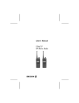
LBI-39110 Mobile Communications ALLEGRATM DUPLEX PORTABLE RADIO Operator's Manual TABLE OF CONTENTS Page IMPORTANT SAFETY INFORMATION ........................................ 4 SAFETY INFORMATION ......................... 5 OPERATING PROCEDURES.................. 6 INTRODUCTION...................................... 8 USER INTERFACE.................................. BUTTON .............................................. KEYPAD............................................... Function Portion........................... Numeric Portion ........................... Extended Features-1 ................... Extended Features-2 ................... DISPLAY .............................................. Status Indicators .......................... 10 10 10 10 12 12 14 14 14 ALERT TONES ........................................ 15 EDACS APPLICATIONS...................... 15 OPERATION ............................................ 17 Copyright© April 1994, Ericsson GE Mobile Communications Inc. 2 GENERAL ............................................ 17 Turning The Radio ON/OFF........................................ 17 Volume Adjust .............................. 17 EDACS OPERATION ........................... 17 System SelectionRamping Names ......................... 17 System SelectionDirect Number Entry ............................................ 18 Group SelectionRamping Names .......................... 18 This manual is published by Ericsson GE Mobile Communications Inc., without any warranty. Improvements and changes to this manual necessitated by typographical errors, inaccuracies of current information, or improvements to programs and/or equipment, may be made by Ericsson GE Mobile Communications Inc., at any time and without notice. Such changes will be incorporated into new editions of this manual. No part of this manual may be reproduced or transmitted in any form or by any means, electronic or mechanical, including photocopying and recording, for any purpose, without the express written permission of Ericsson GE Mobile Communications Inc. TABLE OF CONTENTS (CONTINUED) Group SelectionDirect Number Entry..................... 18 Unlocking The Radio .................... 18 Locking The Radio........................ 19 Programmable Flex Keys ............. 19 Interconnect Dialing...................... 19 REDIAL Key ................................. 19 Individual Call Dialing ................... 19 Individual Call Notification............. 20 Storing An Individual Call ID......... 20 Using Special Call Lists ................ 20 Storing A Telephone Number To The Call List ............................ 21 Recalling calls from the call list..... 21 Simplex Operation ........................ 21 */System Key usage ..................... 21 CLR key Usage & Last Digit Clear And Display Clear ............... 22 1/ALERT Key................................ 22 2/Call Timer .................................. 22 4/EXT MIC.................................... 23 5/SIMPLEX ................................... 23 6/MUTE ........................................ 23 8/SCAN......................................... 24 9/SCAN ADD/DEL ....................... 0/SPC .......................................... Pause........................................... PROGRAMMABLE OPTIONS ............. Call Time-outs.............................. Emergency................................... Automatic Login ........................... Wide Area System Scan............. Supervisory Mode........................ Programmable Audio/Display ...... Priority System Scan.................... Group Options.............................. TX Disable-Group Option............. Rx Disable-Group Option............. Control Channel Limits................. 24 24 24 25 25 25 26 26 26 26 26 26 26 26 27 CLEANING INSTRUCTIONS................... 27 BATTERIES AND RECHARGING ........... 27 AVAILABLE OPTIONS............................. 34 FREQUENTLY CALLED NUMBERS ....... 35 3 IMPORTANT SAFETY INFORMATION * Some of the following information may not apply to your particular product. However, as with any electrical product, precautions should be observed during handling and use. * * * * * * * 4 Save this manual, it contains important safety and operating instructions. Before using the product, please follow and adhere to all warnings, safety and operating instructions located on the product and in the user's manual. Save all instructions for future reference. Do Not expose product to water or moisture. Example: near bathtub, laundry sink, wet basement, swimming pools, etc. Do Not expose product to extreme temperatures such as found near a hot radiator or stove, or in a car parked in the summer sun. Do Not expose product to lighted candles, cigarettes, cigars, open flames, etc. Care should be taken so that objects do not fall or liquids do not spill into the product. * * * * * Do Not use auxiliary equipment not recommended or sold by the manufacturer. To do so may result in a risk of fire, electric shock or injury to persons. Connect optional AC adapter only to 110 VAC power source as marked on the product. Connect the DC power cord only to 12-14 VDC power source as marked on the product. To reduce risk of damage to electric cord, pull by AC adapter rather than cord when disconnecting unit. Make sure the cord is located so that it will not be stepped on, tripped over or otherwise subjected to damage or stress. To reduce risk of electrical shock, unplug unit from power source before attempting any cleaning, then use soft cloth dampened only with water. DANGER - Never alter AC cord or plug. If it will not fit outlet, have a proper outlet installed by a qualified electrician. Improper connection can result in risk of an electric shock. * * * Do Not attempt to disassemble the product. This product does not contain customer serviceable components. Damage Requiring Service - This product should be serviced by qualified service personnel when: A. The power supply cord or the plug has been damaged; or B. Objects have fallen, or liquid has been spilled into the product; or C. The product has been exposed to rain or moisture; or D. The product does not appear to operate normally or exhibits a marked change of performance; or E. The product has been dropped, or the cabinet damaged. If an outdoor antenna is connected, be sure the system is grounded so as to provide some protection against voltage surge and built-up static charges. An outdoor antenna should be located away from power lines. SAFETY INFORMATION The operator of any portable radio should be aware of certain hazards common to the operation of vehicular radio transmissions. A list of possible hazards follows: 1. Explosive Atmospheres Just as it is dangerous to fuel a vehicle with the motor running, be sure to turn the radio off while fueling the vehicle. Do not carry containers of fuel in the trunk of the vehicle when the radio is mounted in the trunk. 2. Interference to Vehicular Electronics Systems Electronic fuel injection systems, electronic anti-skid braking systems, etc., are typical of the type of electronic devices that may malfunction due to the lack of protection from radio frequency energy present when transmitting. If the vehicle contains such equipment, consult the dealer of your vehicle and enlist his aid in determining if such 5 electronic circuits perform normally when the radio is transmitting. 3. Dynamite Blasting Caps Dynamite blasting caps may be caused to explode by operating a radio within 500 feet of the blasting caps. Always obey the "Turn Off Two Way Radios" signs posted where dynamite is being used. When transporting blasting caps in your vehicle: 4. a. Carry the blasting caps in a closed metal box with a soft lining. b. Leave the radio OFF whenever the blasting caps are being put into or removed from the vehicle. Radio Frequency Energy To prevent burns or related physical injury from radio frequency energy, do not operate the transmitter when anyone outside of the vehicle is within two feet of the antenna. 6 5. Liquefied (LP) Gas Powered Vehicles Portable radio installations in vehicles powered by liquefied petroleum gas with the LP gas container in the trunk or other sealed-off space within the interior of the vehicle must conform to the National Fire Protection Association standard (NFPA) 58 requiring that: a. The space containing the radio equipment shall be isolated by a seal from the space containing the LP gas container and its fittings. b. Outside filling connections shall be used for the LP gas container. c. The LP gas container shall be vented to the outside of the vehicle. OPERATING PROCEDURES Two-way FM radio systems must be operated in accordance with the rules and regulations of the Federal Communications Commission (FCC). Operators of two-way radio equipment must be thoroughly familiar with the rules that apply to the intended type of radio operation. Following these rules helps to eliminate confusion, assures the most efficient use of existing radio channels, and results in a smoothly functioning radio network. When using this two-way radio remember these rules: 1. 2. 3. It is a violation of FCC rules to interrupt any distress or emergency message. As the radio operates in much the same way as a telephone "party line", always listen to make sure that the line is clear - that no one else is on the air - before sending messages. If someone is sending an emergency message - such as reporting a fire, or asking for help in an accident - KEEP OFF THE AIR! Emergency calls have priority over all other messages. NOTE ® The EDACS trunking environments have automatic identification features built in and do not require the user to identify by means of call letters. 4. The FCC requires that conversations be kept brief and confined to business. To save time, use coded messages whenever possible. 5. Using a radio to send personal messages (except in an emergency) is a violation of the FCC rules. Send only those messages that are essential for business operation. 6. It is against Federal law to repeat or otherwise make known anything overheard on the radio. Conversations between others sharing a channel must be regarded as confidential. 7. The FCC requires the operator to transmit station identification at certain times by means of call letters. Refer to the FCC rules Use of profane or obscene language is prohibited by Federal law. It is against the law to send false call letters, or a false distress or emergency message. 7 for your station's particular type of operation for the proper procedure. 8. No changes or adjustments shall be made to the equipment except by an authorized or certified electronics technician. INTRODUCTION This manual describes how to use the Allegra Duplex Portable Radio. The Allegra Duplex is a synthesized, microprocessor-based, high performance duplex portable FM radio providing reliable two-way communications in Enhanced Digital Access Communications System (EDACS) trunking environments. Duplex operation is provided in EDACS systems while operating in the Telephone Interconnect Mode. At all other times, the radio 8 provides simplex communications, i.e. when placing group calls in the EDACS environments or when operating in the conventional mode. In an EDACS trunked environment the user selects a communications system and group. In this mode, channel selection is transparent to the user and is controlled via digital communication with the system controller. This provides advanced programmable features and fast access to communication channels. The exact operation of the radio depends on the operating mode, the radio's programming, and the particular radio system. Most features described in this manual may be enabled or disabled through programming. Consult the system administrator for the required features to be programmed into the radio. The portable radio has an antenna which can be unfolded so that it points directly upwards and, when not in use, can be folded down completely. The 20-button keypad, an internal speaker and a liquid crystal display (LCD) for radio status information are located on the front of the radio. Viewed from the radio's front, a Push-To-Talk (PTT) button is located on the left side . 9 The keypad is used for manual number entry for individual calls, access to a telephone interconnect system and activation of various EDACS or conventional features. The keypad is divided into both a function portion and a numeric portion as is found on a basic push-button telephone. The display has an eight alphanumeric character line (upper line) used to show the operational mode of the radio and has a numeric character line (middle line) used to show talk time. Eight status indicators, used to indicate various operating conditions, such as; function key pressed, transmitter on, service available, radio in use, horn alert active, radio locked or transmit muted, are located below the character lines within the display. USER INTERFACE BUTTON PUSH–TO–TALK Enables the radio's transmitter. (PTT) BUTTON PTT must be held down to transmit during simplex opera tion. 10 KEYPAD Function Portion Two functions button; 1. Momentarily Press. Terminates any ongoing activity. If the radio is designated as supervisory, it drops any ongoing group call. 2. Press and Hold (approximately 2 seconds). Applies power to the radio. Press and hold the ON/END button to turn the radio on. All status indicators turn on momentarily and after 2 seconds a short beep is heard and the message “---ON---” will be displayed on the LCD. Press a second time to turn the radio off. After 2 seconds short beep is heard and the message “TURN OFF” will be displayed on the LCD. When turned off, the radio retains the last user selections (unless programmed for a particular power up option). Initiates a call by sending the number shown in the display, or functions as the PTT button if no number has been previously entered. Clears the last digit entered when pressed and released. Press and hold for at least one second to clear the entire number. NOTE When the VOLUME UP or VOLUME DOWN button is pressed, the volume setting can be momentarily displayed on the LCD (e.g., VOL=15) if the radio is not actively receiving a call and the function is enabled through programming. If not programmed with a power up volume level, the radio retains the last setting used when the radio was powered off. Stores numbers in memory locations. Activates extended features. The extended features are labeled above each associated key on the keypad. is pressed before the associated key to enable the secondary function of that key. The extended keyboard is available as long as the FCN icon is displayed Recalls numbers from memory locations. 11 VOLUME UP BUTTON DURING A CALL - sends the DTMF tone for #. Increases the volume level. 15 is the maximum level. Provides a pause during keypad entry of the DTMF numbers. This function is activated, when a first number 0..9 of the request telephone number was pressed. VOLUME DOWN BUTTON Decreases the volume level. 00 is the minimum level unless programmed otherwise. Extended Features - 1 Numeric Portion — Enters telephone numbers and activates extended features. Ramps through the system list and selects a system. DURING A CALL - sends the DTMF (Dual-Tone Multi-Frequency) tone for *. IN DISPATCH MODE - brings up the dial tone. Ramps through the group and channel list and selects a group or channel . 12 Press keys or buttons. Key first then one of the following Function Comments ALERT Enables/disables the horn alert feature. Once to turn on, again to turn off. TIME Displays call timer (active if call is in progress, last call length if call is not in progress). OVERDIAL Enables overdial mode for placing/storing dispatch overdial calls. EXT MIC Toggles between external and internal microphone. SIMPLEX Toggles between simplex only and duplex operation. MUTE Enables/disables microphone mute during duplex operation. LOCK Locks the radio and keypad. (Provided code has been pre-programmed). SCAN Enables/disables group scan operation. ADD/DEL Adds or deletes groups from the scan list. SPC Enters Special Call Mode. SYSTEM Changes the ramp direction for systems or directly accesses systems. GROUPS/ Changes the ramp CHANNELS direction for groups or channels or directly accesses groups. A Flex Keys that can be used in two ways: B 1) quick dial frequently called or emergency numbers, C 2) extended functions such as Special Calls, Public Address, Horn Alert, Emergency, or Home System/Group. Each "Flex Key" can store one number for a total of three. RING Set the one of the four ring volume level. RING MIN, RING -2-, RING -3-, RING MAX 13 Extended Features - 2 Press and hold following keys twice. Key Function first and one of the Comments TESTMODE Enters testmode (if enabled). ver group key to display Hold current software Group Version (as GXX VXX). Status Indicators Eight status indicators show the various operating characteristics of the radio. Indicators are displayed to show the current operating status of the radio. FCN Indicates an extended function is currently being selected. PWR Indicates the transmitter is active. SERV Indicates the radio is in the range of a system and the control channel is available . DISPLAY The radio's display is shown below. The alphanumeric field is used to display system and group or channel names and also operational messages to the user. This line contains eight 14-segment alphanumeric characters. The middle numeric field displays call time length in minutes and seconds. The bottom line displays eight status flags . Indicates the radio is receiving a signal on the selected channel or group. (IN USE) 14 EDACS APPLICATIONS A B ∆ þ Indicates the radio is configured to notify the user via an external alarm that an individual call has been received. Not used. Indicates the radio’s keypad is locked. Mute icon - indicates the radio has the transmit audio disabled (only valid during duplex operation). ALERT TONES The Allegra Duplex radio generates a set of unique alert tones to indicate operating status. The following section identifies and describes the alert tones used in the Allegra Duplex radio for Conventional and EDACS applications . CALL ORIGINATE ALERT If programmed, a short tone is sounded whenever the PushTo-Talk (PTT) button is keyed and the radio has acquired a channel. This tone indicates the user may begin communications. CALL QUEUED If one short, high pitched tone sounds after the transmitter is keyed, this indicates that the system has placed the request in a queue. This tone sounds at both the transmitting unit and the receiving unit(s), indicating to the user on the receiving end that they will receive a call shortly. If the PTT is unkeyed while in queue, the radio autokeys (automatically keys) push-to-talk when a channel becomes available (see AUTOKEY). 15 AUTOKEY When the PTT is keyed to place a call on the system, but the PTT is released before the channel is assigned (e.g. a queued call), the radio automatically keys on the channel when it gets the assignment. The radio generates a long beep and holds the transmitter keyed for two seconds. Pressing the PTT button keeps the channel and sends the message before this two second time-out has expired. SYSTEM BUSY If you key the PTT bar and hear three short, medium pitched tones, this indicates that the receiving party is already on the system or the system is busy and its queue is full. You must rekey later to access the system. 16 CALL DENIED A single low pitch beep sounds when the PTT switch is keyed and the request is denied by the system. This happens if the unit is an invalid user or if the unit is requesting an unavailable service. OUT OF RANGE SYSTEM INOPERATIVE A single low pitched tone sounds immediately after the PTT switch is keyed indicating the radio is out of range of the repeater. The radio tries to place the call for a short period (3 seconds) after the initial attempt. The radio generates a second low pitched tone when it gives up trying to place the call. The system is off the air or the radio needs servicing when the radio is within calling range, and these tones are heard. OPERATION GENERAL Turning The Radio ON/OFF The radio is powered ON by pressing and holding the button. All status indicators turn on momentarily and after 2 seconds a short beep will be heard and a message “---ON---” will be displayed on the LCD. A self diagnostic test is performed when the radio is first turned on if enabled through programming. To turn the radio Volume Adjust The user can adjust the volume at any time and buttons. If the volume is using the adjusted while a call is in progress, no audible beeps are heard. If no call is in progress, a short beep is heard, in addition to the visual indication, if enabled. Additionally, the user selected “off-hook” volume level is saved separately from the user selected “on-hook” volume level. EDACS OPERATION System Selection-Ramping Names button again. After OFF press and hold the 2 seconds a short beep will be heard and a message “TURN OFF” will be displayed on the LCD. When turned off, the radio retains the last user selections (unless programmed for a particular power up option). key is used to Additionally, the terminate interconnect and individual calls. The operator can ramp through the programmed system names list by pressing and releasing the key. If the radio is programmed for a non-split display then the selected talk group is displayed when the radio is idling. The first time the key is pressed the radio displays the selected system name. This name remains on the display 17 for the programmed display time-out period. If the is released and then pressed again during this time the radio ramps to the next system name in the list. If the radio is programmed for a split display then both the selected system and group are displayed when the radio is idling. The first time the key is pressed the radio ramps to the next system name in the list. The ramp direction through the system name list is selectable. It is toggled by pressing the key. Group Selection-Ramping Names The desired group is selected by pressing and releasing . The ramp direction of the group selection is changed by pressing then and . Group Selection-Direct Number Entry Direct group selection can be made by entering (1) the group selection digit(s), (2) pressing , (3) pressing . If an invalid group number is entered, the first group is selected. System Selection-Direct Number Entry Unlocking The Radio Direct system selection can be made by entering (1) the system selection digit(s), (2) pressing , (3) pressing . If an invalid number is entered, the first system is selected. 18 After the portable is locked the user can unlock the portable by keying in the lock code. If an incorrect digit is entered simply start over with the correct code. If the lock code is forgotten, contact the system operator. Locking The Radio REDIAL Key The radio can be locked by pressing . The ∆ icon is displayed. In this followed by mode calls cannot be originated. This feature is operational only if a lock code is entered during radio programming. Lock codes can be 1 to 15 digits long. Programmable Flex Keys Pressing the key and then the key, redials the last number dialed. Individual Call Dialing To place an individual call, the user enters the desired LID number and presses the PTT. To program the Flex Keys enter the following key sequence: Flex keys automatically recall and execute the function stored at that location without further 1. Enter the desired phone number/LID. user intervention. 2. Press the -(A), function. Pressing -(B) or followed by -(C) activates the a phone number or the if the number is a radio LID or dispatch overdial/ID. Interconnect Dialing To place an interconnect call, the user simply enters the desired number using the digit (9-0) keys and presses the key. key if the number is key. 3. Press the 4. Press the A, B, or C key that is to be associated with this call number. 19 When a Flex Key is PC programmed, it is locked, thus preventing the user from re-programming its function. Storing An Individual Call ID This type of call is dynamically stored to the call list by following the following steps: Individual Call Notification 1. When an individual call is received the caller's ID is stored and is displayed for a programmable time period. After the display time has expired, the last individual call received is recallable by pressing the button or entering Special Call mode. The caller's ID is not saved if the radio is turned off. The user is alerted to the presence of missed individual calls via one of two methods. The default first method is for the radio to display "C*" as the first two characters in the display. The alternate method allows the user to PC program an eight character alphanumeric such as "*MSG*". In combination with these notification methods, the personality can be set-up so that the radio beeps until the user clears the call or toggles the hookswitch. 20 Enter the desired individual call ID then key. 2. followed by the Enter the two digit storage location for the number (00 to 50). The new individual call ID is now added to the call list. Using Special Call Lists In the Allegra Duplex Portable, the difference between a "Call List" and "Special Call List" is that the Call List consists of user modifiable phone numbers and radio LIDs. It operates similarly to a pre-stored phone list in a cellular phone. A "Special Call List" is PC programmable and is not user modifiable. Storing A Telephone Number To The Call List call list using the through the list. The number of dial locations (10, 20, 30, 40, or 50) available is set through radio programming. The maximum number of digits stored in any location is 14. The user may dynamically add phone numbers to the call list by following these steps: 1. Enter the phone number, then followed by 2. , . Enter the two digit storage location for the number (00 to 50). The new phone number is now added to the call list at the specified location. Recalling calls from the call list Each pre-stored call number has a corresponding phone number. To dial the phone number, select the 2 digit call number and press key to scroll forward Simplex Operation The user can choose to terminate duplex operation and still maintain the interconnect call in progress by pressing followed by . This key sequence toggles between simplex and duplex operation. */System Key usage The /System ramp button is used in multiple contexts. When pressed while in monitor mode (i.e. radio is not in a special or interconnect call) the radio ramps through available systems in one direction. If followed by /System is pressed, system ramping takes place in the opposite direction. If this key is pressed after any key other than returned. the is . Alternately, the user can scroll through the 21 CLR key Usage - Last Digit Clear And Display Clear To clear the last digit entered in the display, momentarily press display, press and hold second. . To clear the entire for at least one For functions without associated icons the current status is displayed by pressing key followed by the desired function. At that time the current state is displayed in the radio's character display. If the state is to be changed, the user must again press the desired function key at which time the new state is displayed. Once the user is satisfied with the selection, let the display expire by not pressing any keys, or press that the current activity has ended. to signify Additionally, if the radio is programmed as a supervisory radio, the 22 key can be used to terminate activity, i.e. clear emergencies ( A, B, or C for 2 seconds), drop calls, etc. 1/ALERT Key The horn alert option can be pre-programmed to: 1) generate a 1 second horn blast, 2) generate three 1/2 second horn blasts, or 3) generate a continuous horn blast when a call is received. This function is enabled or disabled by pressing and then . Pressing PTT during the alert tone prevents blowing the horn. The horn alert remains enabled for subsequent calls until disabled. 2/Call Timer The call timer function causes the time duration for the current interconnect call to be displayed. Note that the call timer starts when an interconnect call is initiated. During a conversation the call timer is displaying on the middle line of LCD. The time display is automatically removed after a preset time-out or can be removed from the 5/SIMPLEX display by pressing followed by . refresh by pressing Time of the last interconnect call will be displayed. When operating in the simplex mode, the MUTE icon follows the state of the transmit audio. While in simplex mode, PTT must be pressed prior to speaking. (NOTE: Applicable only in the interconnect mode.) 4/EXT MIC (HANDSFREE) 6/MUTE The external mic (Handsfree) option routes audio to an external Portable or Vehicle Handsfree This function enables the user to mute the transmit audio when operating in the duplex mode. To disable the microphone so the called party . Call timer can be unit. To enable the external mic, press followed by . Toggling this function provides the user with the capability to have private conversations or allow other passengers in the vehicle to participate in the conversation (Vehicular Option). The character display shows "INT MIC" if the internal speaker/mic is currently active. To toggle the state to the external speaker/mic press cannot hear the conversation, press followed by . MUTE is displayed. Re-enable the microphone using the same key press sequence. The call is muted only for the duration of the current interconnect call. key twice while the FCN icon is on. (NOTE: With an external device connected the Allegra will always “power-up” with the external unit enabled.) 23 8/SCAN with “S” means the group is “in scan”. To exit, Scan operation is controlled by this key sequence (i.e. followed by /SCAN). Display will read “SCAN ON” or “SCAN OFF”. (Note: Scan must be off to add/delete groups). press the key. 0/SPC the scan list. To edit the scan list, press Entering followed by /SPC accesses the Special Call List. This list is a programmable set of call numbers that the user can invoke by scrolling to the desired call number in the alpha-numeric display and then depressing the PTT. Scrolling forward through this list is done followed by by pressing 9/SCAN ADD/DELETE Note: scan must be turned off before editing . The upper display line will again. The show “SCAN A/D”. Press display should change to the current group name. Press to ramp up to the group to be changed. Then press to ramp through the scan options. For a trunked system, these options are “not in scan” and “in scan”. For a conventional system, the options are “not in scan”, “in scan” a “priority 2 channel”, or a “priority 1 channel”. The scan state replaces the first two letters of the group name. The complete group name means the group is “not in scan”. A display line beginning 24 /GROUP. Scrolling backward through this list is done by pressing followed by /GROUP. (See Special PC programming functions in TQ-3373, for programming of the Special Call List.) Terminate Special Call List access by pressing . Pause A pause is entered into a stream of DTMF numbers being dialed via the keypad. The operator enters or pause is PC programmable. . The length of PROGRAMMABLE OPTIONS Call Time-outs The Allegra Duplex Portable provides several time-out options to accommodate user needs. They are summarized below: Carrier Control Timer (CCT) This timer is provided to limit continuous transmit time (when not in a duplex mode of operation). A single value can be selected that applies to all trunked operation. Each conventional channel has the option of enabling or disabling the timer on a per channel basis. Voice Scan Lockout Timer Provides a time limit that disables group scanning following initiation of a voice call. Special Call time-out Drops the radio out of special call mode after a specified period of operator inactivity. Individual/Interconnect Call time-out A time-out that drops the radio out of an individual/interconnect call after a specified period of time. Emergency Any one of the three Flex Keys (A, B, or C) can be programmed to function as the emergency button. If the radio is programmed as a supervisory radio, it is allowed to clear emergencies from the system. When the message “EMRGNCY” is displayed, pressing the button followed by the Emergency button (combination A, B, or C) causes the radio to attempt to clear the emergency. 25 Automatic Login Priority System Scan The Allegra Duplex Portable supports Automatic Login for EDACS trunked systems. This option allows the Allegra Duplex Portable to search for a second operating system while locked onto the control channel of the selected system. If a second control channel is found, the radio switches to that system. The scan frequency is programmable. Wide Area System Scan The Allegra Duplex Portable supports Wide Area Roaming. When scanning, there is a programmable time interval that determines when the radio starts scanning the next site. Supervisory Mode When a Allegra Duplex Portable is programmed as supervisory, it is capable of handling all normal supervisory functions. Programmable Audio/Display Each EDACS system has a programmable option to handle display and audio during emergency conditions. When an emergency occurs, the display option can be programmed to hold the display unchanged until the PTT button is pressed or the emergency is cleared. The audio option, similarly, causes the radio to remain muted until PTT is pressed or the emergency is cleared. 26 Group Options Each EDACS trunked system uses a set of groups. Each set allows for a home Group ID, Dynamic Regroup/encoding, and Emergency calls. In addition to each group ID the following options are supported. TX Disable-Group Option This option prevents keying a radio on a particular group (monitor only). Rx Disable-Group Option This option prevents unmuting a radio on a particular group. Control Channel Limits This option provides for limited scanning of a frequency set for a control channel. When programmed, the radio is only capable of scanning a subset of channels for a control channel. This is useful in large wide area scanning systems to speed up the scan process. CLEANING INSTRUCTIONS The radio can be cleaned with a damp cloth, using a mild solution of liquid detergent and water or with a soft cloth and furniture polish. Never use an abrasive or a petroleum based solvent cleaner. BATTERIES AND RECHARGING BATTERIES Battery Voltage Indicator A battery voltage is shown on the alphanumeric line of the display, when BATT keys ). “BATT-6,0” means are pressed ( , that the battery has a charge of 6.0 Volts. A fully charged battery will have 6.5 Volts or more. A battery which is almost empty will have 5.6 Volts or less. Low Battery Alarm As a reminder that the attached battery needs recharging or replacing, an alarm signal sounds for a short time and the message “LOW BATT” appears in the display. Additionally, the red low battery LED indicator located on the top side of the radio will flash. If the radio is left on, the low battery alarm will be repeated several times and, eventually, the radio will turn itself off. 27 If the low battery alarm sounds will a call is in progress, you should end the call . If the call continues, the radio will turn itself off after a short period. CARE AND MAINTENANCE INSERTING AND REMOVING A BATTERY Standard Battery Removal: The batteries are of the Nickel-Cadmium type. They have a long maintenance-free service life if properly treated. * * * 28 Never let a battery get into contact with metal objects that may short-circuit the battery poles, for example a bunch of keys in a pocket. Do Not disassemble a battery. A battery may explode if disposed of in a fire. Insertion: Optional High Capacity Battery If you are uncertain of the state of charge of a battery, you can attach the battery to the radio. If Removal: Grasp and move buttons in direction away from radio unit. Lift battery up and away from radio unit. the radio does not come on when the (Power) key is pressed, the battery is probably empty. Insertion: SLIDE INDICATOR The battery has a slideable indicator which you can use to tell an empty battery from a charged battery. Slide the indicator to the left if the battery is empty, to the right if the battery is charged. 29 RECHARGING Avoid recharging a battery before the low battery alarm has been issued, unless a Smart Charging Accessory is used. Never recharge a battery when the ambient temperature is below 10°C or 50°F, or above 40°C or 105°F. push it in. As the connector makes contact, the arrow-shaped LEDs on the charger’s face flash yellow. Charging a Battery Out of the Phone 1. Locate the end of the battery with rectangular charging contacts. The contacts are labeled + and -. 2. If you are charging a Standard battery, lift the retaining tab in the vertical compartment to hold the battery in place. Using Rapid Multi-Charger The charger will not charge if the ambient temperature is below 25°F or above 105°F or if the battery voltage is below 3 V. 1. Plug the AC converter into an AC outlet. 2. Position the converter cable connector so that it fits in the jack on the end of the charger and 30 If you are charging a High Capacity battery in the vertical compartment, leave the tab down. 3. Place the battery in the vertical compartment with the rectangular charging contacts down and the inner surface of the battery toward the center of the charger. 4. When you remove the battery from the charger, move the orange slide indicator on the battery to the plus position as a reminder that the battery is fully charged. Charging While the Battery is in the Phone 1. 2. Place the phone in the vertical compartment with the keypad facing the center of the charger. When the battery is seated, the LED shows red to indicate that the battery is charging. Charging Your Battery To place Standard or High-capacity batteries in the horizontal compartment, use the following procedure. Make sure the retaining tab in the vertical compartment of the charger is down. 31 1. Locate the end of the battery with round charging contacts. 2. Orient the battery with its inner surface down and place the round charging contacts on the pins in the horizontal compartment. Press the battery into place. The arrow LED pointing to the horizontal compartment should light up. 1. To remove a Standard battery, press the battery forward toward the pins and pull up. To remove a High-capacity battery, squeeze and pull back on both of the battery’s side release buttons and lift up and away from the charger. 2. When you remove the battery from the charger, move the orange slide indicator on the battery to the plus position as a reminder that the battery is fully charged. Removing Battery Using the Rapid Travel Charger Follow these procedures to remove a Standard or a High-capacity battery from the horizontal compartment. 32 1. Connect the charger cable to the bottom of the radio unit. This will permit the charging of the standard battery (only) or to power the radio. 1. 2. 2. Plug the AC Adapter into a 120 VAC wall outlet. Using Smart Charging Accessories Some accessories supply power that the radio controls to charge the battery. Most batteries can be charged in under 2 hours. When charging has been completed, or the phone is off, the power is reduced. The phone may remain connected to the accessory for as long as you wish. If the battery has not been used for several months, connect the radio to the accessory for a few minutes before turning on the radio. 3. Use the radio as you normally would, until the low battery alarm has been issued. Allow the radio to remain on until it turns itself off. Charge the battery using either the desk-top charger or a Smart Charging Accessory. After discharging and recharging the battery this way, it can be used for a longer period before the next recharge is required. To get the longest period between charges, repeat this procedure 3 or 4 times. Also if battery has not been used for several months, it may require 3 or 4 charge-discharge cycles to return to full capacity. Restoring Battery Capacity If you often recharge a battery before the low battery alarm has been issued, the battery’s ability to accept charge will be impaired. This will result in less and less operating time between recharges. To restore the battery, perform the following: 33 AVAILABLE OPTIONS The following equipment options are available for the Allegra Duplex Portable. Refer to your radio supplier for ordering information. OPTION DESCRIPTION DYPA5Z 900 mAh Standard Battery DYPA7A 1400 mAh High Capacity Battery DYCH5B AC Rapid Multi-Charger for Slimline, Standard & High Capacity Batteries 34 DYCH5DF AC Rapid Travel-Charger DYCF1F Power Adapter Plus, allows the Allegra to be powered through a vehicle cigarette lighter receptacle and/or re-charges a standard or slimline battery. DYMN7A Vehicle Handsfree Install Package. PART NUMBER FREQUENTLY CALLED NUMBERS MEMORY LOCATION NAME TELEPHONE NUMBER 01 02 03 04 05 06 07 08 09 10 11 12 13 14 15 16 17 18 19 20 21 22 23 24 35 25 26 27 28 29 30 31 32 33 34 35 36 37 38 39 40 41 42 43 44 45 46 47 48 49 50 36 NOTES: 37 NOTES: 38 WARRANTY A. Ericsson GE Mobile Communications Inc. (hereinafter "Seller") warrants to the original purchaser for use (hereinafter "Buyer") that Equipment manufactured by Seller shall be free from defects in material, workmanship and title, and shall conform to its published specifications. With respect to any Equipment not manufactured by Seller (except for integral parts of Seller's Equipment to which the warranties set forth above shall apply). Seller gives no warranty, and only the warranty, if any, given by the manufacturer shall apply. Batteries are excluded from this warranty but are warranted under a separate Nickel-Cadmium Battery Warranty. B. Seller's obligations set forth in Paragraph C below shall apply only to failures to meet the above warranties (except as to title) occurring within the following periods of time from date of sale to the Buyer and are conditioned on Buyer's giving written notice to Seller within thirty (30) days of such occurrence: 1. for fuses, incandescent lamps, vacuum tubes and non-rechargeable batteries, operable on arrival only. 2. for parts and accessories (except as noted in B.1) sold by Seller's Service Parts Operation, ninety (90) days. 3. for all other Equipment of Seller's manufacture, one (1) year. C. If any Equipment fails to meet the foregoing warranties, Seller shall correct the failure at its option (i) by repairing any defective or damaged part or parts thereof, or (ii) by making available at Seller's factory any necessary repaired or replacement parts. Any repaired or replacement part furnished thereunder shall be warranted for the remainder of the warranty period of the Equipment in which it is installed. Where such failure cannot be corrected by Seller's reasonable efforts, the parties will negotiate an equitable adjustment in price. Labor to perform warranty service will be provided at no change only for the Equipment covered under Paragraph B.3, and only during the first three (3) months following the date of sale to the Buyer. Thereafter, labor will be charged at prevailing rates. To be eligible for no-charge labor, service must be performed by an authorized General Electric Service Station or other Services approved for these purposes either at its place of business during normal business hours, for mobile or personal equipment, or at the Buyer's location, for fixed location equipment. Service on fixed location equipment more than thirty (30) miles from the Service Station or other approved Service’s place of business will include a charge for transportation. Equipment located off-shore is not eligible for no-charge labor. D. Seller's obligations under Paragraph C shall not apply to any Equipment, or part thereof, which (i) has been modified or otherwise altered other than pursuant to Seller's written instructions or written approval or, (ii) is normally consumed in operation or, (iii) has a normal life inherently shorter than the warranty periods specified in Paragraph B, or (iv) is not properly stored, installed, used, maintained or repaired, or, (v) has been subjected to any other kind of misuse or detrimental exposure, or has been involved in an accident. E. The preceding paragraphs set forth the exclusive remedies for claims (except as to title) based upon defects in or nonconformity of the Equipment, whether the claim is in contract, warranty, tort (including negligence), strict liability or otherwise, and however instituted. Upon the expiration of the warranty period, all such liability shall terminate. The foregoing warranties are exclusive and in lieu of all other warranties, whether oral, written, expressed, implied or statutory. NO IMPLIED OR STATUTORY WARRANTIES OF MERCHANTABILITY OR FITNESS FOR PARTICULAR PURPOSE SHALL APPLY. IN NO EVENT SHALL THE SELLER BE LIABLE FOR ANY INCIDENTAL, CONSEQUENTIAL, SPECIAL, INDIRECT OR EXEMPLARY DAMAGES. This warranty applies only within the United States. ECX-362R 6/90 Printed in U.S.A. 39 EMERGENCY NUMBERS Police State Police Fire Poison Control Ambulance Life Saving and Rescue Squad Printed in U.S.A.