1
SifoWorks U100 User Manual 1.0
OD7100UME01 – 1.0
IMPORTANT NOTICE
No portion of O2Micro specifications/documents or any of its subparts may be reproduced in any
form, or by any means, without prior written permission from O2Micro.
O2Micro and its subsidiaries reserve the right to make changes to their documents and/or
products or to discontinue any product or service without notice, and advise customers to obtain
the latest version of relevant information to verify, before placing orders, that information being
relied on is current and complete. All products are sold subject to the terms and conditions of
sale supplied at the time of order
acknowledgement, including those pertaining to warranty,
patent infringement, and limitation of liability.
O2Micro warrants performance of its products to the specifications applicable at the time of sale
in accordance with O2Micro's standard warranty. Testing and other quality control techniques
are utilized to the extent O2Micro deems necessary to support this warranty. Specific testing of
all parameters of each device is not necessarily performed, except those mandated by
government requirements.
Customer acknowledges that O2Micro products are not designed, manufactured or intended for
incorporation into any systems or products intended for use in connection with life support or
other hazardous activities or environments in which the failure of the O2Micro products could
lead to death, bodily injury, or property or environmental damage ("High Risk Activities").
O2Micro hereby disclaims all warranties, and O2Micro will have no liability to Customer or any
third party, relating to the use of O2Micro products in connection with any High Risk Activities.
Any support, assistance, recommendation or information (collectively, "Support") that O2Micro
may provide to you (including, without limitation, regarding the design, development or
debugging of your circuit board or other application) is provided "AS IS." O2Micro does not make,
and hereby disclaims, any warranties regarding any such Support, including, without limitation,
any warranties of merchantability or fitness for a particular purpose, and any warranty that such
Support will be accurate or error free or that your circuit board or other application will be
operational or functional. O2Micro will have no liability to you under any legal theory in
connection with your use of or reliance on such Support.
COPYRIGHT © 2007, O2Micro International Limited
Table of Contents
Getting Started....................................................................................... 1
Logging into the System................................................................................1
Logging Out from the System ........................................................................2
System Administration
1.
2.
3.
Administrator Management ................................................................. 3
1.1 Administrator Accounts............................................................................3
1.2 Permitted Login IPs .................................................................................4
Basic System Configurations................................................................ 5
2.1
2.2
2.3
2.4
Basic Settings ........................................................................................5
System Date and Time Settings ................................................................7
Language Settings ..................................................................................8
Software Update.....................................................................................8
Network Settings ............................................................................... 9
3.1
3.2
3.3
3.4
3.5
3.6
Configuring the Physical Interfaces ............................................................9
Configuring Multiple Subnets .................................................................. 15
Route Table ......................................................................................... 17
Setting DHCP ....................................................................................... 17
Dynamic DNS ....................................................................................... 19
Host Table ........................................................................................... 20
Access Policy Management
4.
5.
6.
Policy Object Management .................................................................21
4.1
4.2
4.3
4.4
4.5
Address Objects.................................................................................... 22
Service Objects .................................................................................... 24
Schedule Objects .................................................................................. 25
Quality of Service ................................................................................. 26
Content Blocking Objects ....................................................................... 27
Authentication ..................................................................................29
5.1
5.2
5.3
5.4
5.5
Internal Authentication Server Settings.................................................... 29
Using an External RADIUS Server............................................................ 30
Using an External POP3 Server ............................................................... 31
Authentication Users ............................................................................. 31
Authentication User Groups .................................................................... 32
Virtual Service ..................................................................................33
6.1 Mapped IP ........................................................................................... 33
6.2 One-to-Many Virtual Server Mappings...................................................... 35
7.
8.
Firewall Policy Management ................................................................37
7.1
7.2
7.3
7.4
7.5
7.6
7.7
Outgoing Policies .................................................................................. 37
Incoming Policies .................................................................................. 40
WAN to DMZ Policies ............................................................................. 42
LAN to DMZ Policies .............................................................................. 43
DMZ to WAN Policies ............................................................................. 45
DMZ to LAN Policies .............................................................................. 45
Application Examples............................................................................. 46
VPN ................................................................................................51
8.1
8.2
8.3
8.4
IPSec AutoKey...................................................................................... 51
PPTP Server ......................................................................................... 55
PPTP Client .......................................................................................... 57
Trunk .................................................................................................. 59
Security Features
9.
Mail Security ....................................................................................61
9.1
9.2
9.3
9.4
Configuring the Basic Settings ................................................................ 61
Mail Relay ............................................................................................ 61
Anti-Spam ........................................................................................... 62
Anti-Virus ............................................................................................ 69
10. Intrusion Detection and Prevention......................................................71
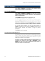
10.1 Basic IDP Settings ............................................................................... 71
10.2 IDP Signatures ................................................................................... 72
10.3 IDP Log Report ................................................................................... 74
11. Anomaly Flow IP ...............................................................................75
11.1 Basic Settings..................................................................................... 75
11.2 Anomaly Flow IP Log ........................................................................... 76
System Monitoring
12. System Monitoring ............................................................................77
12.1
12.2
12.3
12.4
12.5
Logs.................................................................................................. 77
Report ............................................................................................... 80
Statistics ........................................................................................... 81
Wake on LAN...................................................................................... 84
System Status .................................................................................... 84
Getting Started
The SifoWorks U100 system supports Web-based administration,
thus enabling you to configure the system from different operating
systems simply through a standard web browser.
Logging into the System
Activate your preferred web browser (such as Internet Explorer,
Firefox etc.) and enter the system’s IP address into the address bar.
You can use the HTTP (http://IP) protocol to access the WebUI if
enabled in the system’s interface configuration. Please refer to
chapter 3, section 3.1 for details on enabling access through the
HTTP protocol.
Note: On your first login, you should connect to the device’s LAN
interface with default IP address 192.168.1.1. You can then proceed to
configure the system for administrator access via the other interfaces.
Please refer to the SifoWorks UTM Quick Start Guide for details on
setting up access to the SifoWorks web UI.
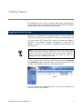
At the prompt, login with your administrator account username
and password. Upon successful login, you will be greeted with the
system’s web interface as shown in the figure below:
You can navigate the system functions via the menu displayed on
the left column of the interface.
SifoWorks U100 User Manual 1.0
1
Getting Started
Logging Out from the System
For security reasons, you should logout of the system after you
have completed your configuration operations. From the left menu,
select “System > Logout > Logout”. At the prompt, confirm that
you want to logout of the system.
You will need to restart your browser if you wish to re-login.
2
SifoWorks U100 User Manual 1.0
1
Chapter
Administrator Management
1.1 Administrator Accounts
SifoWorks U100 comes with a default administrator account with
the username “admin” and password “admin”. This account
cannot be deleted from the system. For security purposes, we
recommend that you change the default password of this account.
Please refer to section 1.1.2 for information on changing account
password.
The SifoWorks U100 default administrator account acts as a main
administrator with read-write authority. This means that this
administrator account is authorized to perform configurations on
the system. There can only be 1 main administrator in the system.
You can also add multiple sub-administrator accounts. All subadministrators are assigned with a read authority. Hence, these
administrators are only authorized to view the system settings and
access the “Monitor” function.
From the left menu bar, select “System > Administration >
Admin” to view the list of administrators. Click the [Remove]
button corresponding to an administrator account in the list to
delete the account.
1.1.1 Adding a New Sub Administrator Account
From the bottom of the list, click [New Sub Admin] to add a new
sub administrator account. Enter the Sub admin name and
account password in the next screen. Retype the password to
confirm and click [OK] to add the new sub administrator.
SifoWorks U100 User Manual 1.0
3
Chapter 1: Administrator Management
1.1.2 Changing an Account Password
From the administrator list, click the [Modify] corresponding to the
account you want to edit. In the next screen, enter the account’s
current password, new password and retype the new password
to confirm. Click [OK] to save the changes.
1.2 Permitted Login IPs
SifoWorks U100 enables the main administrator to restrict the IP
addresses from which administrators can log into the system.
Select “System > Administration > Permitted IPs” to view the
list of permitted IP addresses. You can edit or delete permitted IP
addresses by clicking the appropriate [Modify] or [Remove]
respectively.
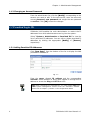
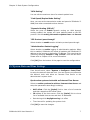
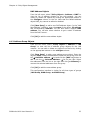
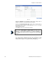
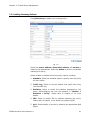
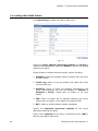
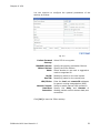
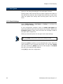
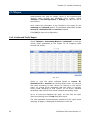
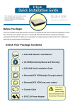
1.2.1 Adding Permitted IP Addresses
Click [New Entry] from the bottom of the list to display the Add
permitted IP address UI.
Fig. 1.1
Enter the name, allowed IP address and the corresponding
netmask. Select whether to allow users logged in through this IP
address to access the Ping and HTTP services.
Note: After configuring the permitted IP, you must disable Ping and
HTTP system management services from the “Interface” function.
Please refer to Chapter 3, section 3.1 for configuration details.
4
SifoWorks U100 User Manual 1.0
2
Chapter
Basic System Configurations
2.1 Basic Settings
Select “System > Configure > Setting” from the left menu. Here,
the main administrator can setup a number of basic system
settings described in the following sections.
2.1.1 Importing/Exporting System Settings
In the “SifoWorks Configuration” portion on the top of the page,
you can import a previously saved configuration file into the system.
Click [Browse…] to select the file to import and click [OK] from
the bottom of the page.
Click the [Download] button to export the current configurations
into a file to be stored in the local disk.
Select Reset factory setting and click [OK] from the bottom of
the page to reset all system configurations to the default factory
setting.
Note: The system will be automatically rebooted after importing the
configuration file. A warning message will be displayed and users will
be able to re-login to the system in about 2 minutes.
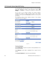
2.1.2 Email Alert Notification Settings
This function enables the system to send email alerts informing
administrators of detected attacks or network emergency conditions.
In the “System Name Setting” portion, enter the device name
used to identify this SifoWorks U100 device.
SifoWorks U100 User Manual 1.0
5
Chapter 2: Basic System Configurations
In the “E-mail Setting” portion, select enable E-mail alert
notification and setup the corresponding parameters including the
sender’s address, SMTP server address and up to 2 recipient email addresses. Click [Mail Test] to check that the configured
recipients are able to receive the alert notification emails.
Click [OK] from the bottom of the page to save the setting.
2.1.3 Reboot System
From the bottom of the page, click [Reboot] to restart the
SifoWorks U100 device.
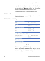
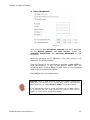
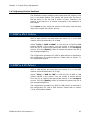
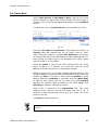
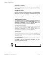
2.1.4 Basic Network Settings
Fig. 2.1
“Web Management (WAN Interface)”
Here you can change the HTTP port number. Note that when this
is modified, the administrator must change his browser’s port
number accordingly when attempting to enter the SifoWorks U100
WebUI (for example, http://192.168.1.1:8080).
6
SifoWorks U100 User Manual 1.0
Chapter 2: Basic System Configurations
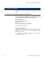
“MTU Setting”
You can edit the maximum size of a network packet here.
“Link Speed/Duplex Mode Setting”
Here, you can set the transmission mode and speed of SifoWorks’ 2
WAN ports when connected to other devices.
“Dynamic Routing (RIPv2)”
Select the ports to enable dynamic routing on. With dynamic
routing enabled, the system will route packets based on the RIP
protocol. Set the routing information update timer and timeout.
“SIP Protocol pass-through”
Select whether to enable session initiation protocol pass-through.
“Administration Packet Logging”
Select whether to enable logging of administration packets. When
this is enabled, SifoWorks will record all packets with SifoWorks’ IP
address as the source or destination IP address. This record can be
viewed by selecting “Monitor > Log > Event” from the left menu.
Please refer to Chapter 12 for more information.
Click [OK] from the bottom of the page to save the configurations.
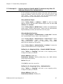
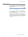
2.2 System Date and Time Settings
From the left menu, select “System > Configure > Date/Time”
to setup the device’s date and time. You can choose to synchronize
the device’s clock with either an Internet Time Server or the
administrator’s system clock.
Synchronize system clock with an Internet Time Server
Select to enable synchronize with an Internet time Server and
setup the parameters accordingly including:
•
GMT offset. Click the [Assist] link to view a list of countries
and their respective GMT offset value.
•
IP address of the time server. Click the [Assist] link to view a
list of available time servers and their IP addresses.
•
Date during which daylight saving is in effect
•
Time interval for updating the system clock.
Click [OK] to save the changes.
SifoWorks U100 User Manual 1.0
7
Chapter 2: Basic System Configurations
Synchronize device’s
system clock
clock
with
administrator
PC’s
Click the [Sync] button next to Synchronize system clock with
this client to synchronize SifoWorks’ clock with the system clock of
the administrator’s PC.
2.3 Language Settings
Select “System > Configure > Language” from the left menu.
The SifoWorks U100’s system can be displayed in 1 of 3 languages
including English, Simplified Chinese and Traditional Chinese. Select
your desired language and click [OK] to change the UI display to
the selected language.
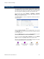
2.4 Software Update
You can update the system’s software using the appropriate update
files here. Select “System > Administration > Software
Update”. Click [Browse…] and select the upgrade file. Click [OK]
to begin the update.
Note: The update process takes roughly 3 minutes. The system will be
automatically rebooted after the update is completed.
We strongly recommend that you do not turn off the PC or leave the
webUI during this period as it may result in unexpected system
problems.
8
SifoWorks U100 User Manual 1.0
3
Chapter
Network Settings
3.1 Configuring the Physical Interfaces
SifoWorks U100 provides 4 interface ports for connection to the
network. This includes 1 LAN port, 2 WAN ports and 1 DMZ ports.
You must first setup the IP address of each port before SifoWorks
can successfully communicate with each connected network.
You can also refer to the SifoWorks UTM Quick Start Guide for
examples on setting up these interfaces.
3.1.1 LAN Interface
Select “Interface > LAN” to configure the LAN interface port.
Enter the IP address and netmask of the connected LAN.
Enabling Ping will allow users on the connected LAN to ping this
interface’s address. Enable HTTP to allow administrators to login to
the device’s WebUI from the connected LAN.
Click [OK] to save the configurations. Please restart the system for
the new LAN IP address to be effective.
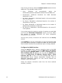
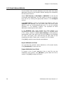
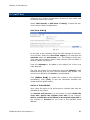
3.1.2 WAN Interface
Select “Interface > WAN” to configure the WAN interface ports.
The list shows the current configurations for the two WAN ports.
Note that the “WAN1” port cannot be disabled while the “WAN2”
port is disabled by default.
Fig. 3.1
SifoWorks U100 User Manual 1.0
9
Chapter 3: Network Settings
From the top of the list, select the balance mode between the two
WAN ports. The available modes include:
•
Auto:
SifoWorks
will
automatically
adjust
the
downstream/upstream bandwidth between the two WAN ports.
•
Round-Robin: SifoWorks
bandwidth in order.
•
By Traffic: Bandwidth is distributed based on the accumulative
traffic on each port.
•
By Session: Bandwidth is distributed based on the number of
connections on each port.
•
By Packet: Bandwidth is distributed based on the number of
packets and connections on each port
•
By Source IP: Bandwidth is distributed based on the source IP
of the packets.
distributes
the
WAN
download
You can also select the maximum number of sessions on each WAN
port from the Saturated Connections column of the list. When
this number is reached, SifoWorks will direct subsequent
connections to the next port.
Set the port’s priority of access to the Internet from the Priority
column.
Click [Modify] to edit the configuration of the corresponding WAN
port. Note that the settings for WAN1 and WAN2 are similar except
that the WAN2 interface has an additional option of being disabled.
Configure the WAN Interface
Setup the service used to perform connection tests on the WAN
interface. If “DNS” is selected, enter the DNS Server IP address
and corresponding Domain name. If “ICMP” is selected, enter the
Alive Indicator Site IP address. You can click the [Assist] link
next to the DNS Server IP Address, Domain name or Alive
Indicator Site IP to view a list of the available DNS Server IP
addresses/DNS Server Domain Name/Alive Indicator Site IP
addresses respectively. Specify the time interval between the
sending of each alive packet.
Select the Internet connection mode from the three methods
available, including:
10
SifoWorks U100 User Manual 1.0
Chapter 3: Network Settings
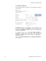
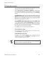
1. “PPPoE”
This refers to ADSL modem connections. The configuration interface
is shown below:
Fig. 3.2
Current Status: The current connection status. You can click the
[Connect] or [Disconnect] button to connect or disconnect the
connection respectively.
IP Address: Displays the IP address of the connection.
Enter the user name and password as registered with the
Internet service provider (ISP). Specify whether the connection IP
address is fixed or dynamic. Enter the IP address, netmask and
default gateway of the connection.
Configure the maximum downstream and upstream bandwidth
of the connection and set the idle time.
SifoWorks U100 User Manual 1.0
11
Chapter 3: Network Settings
2. “Dynamic IP Address”
This is for cable modem connections. The configuration interface is
shown below:
Fig. 3.3
IP Address displays the IP address currently assigned to this
connection by the ISP. Click [Renew] to obtain an IP address from
the ISP. Click [Release] to stop the use of this IP address and
disconnect from the ISP.
If required by the ISP, click [Clone MAC Address] to
automatically configure the system’s MAC address. Enter the
hostname, domain name, user name and password as
provided by the ISP.
Specify the maximum downstream and upstream bandwidth of
this connection.
12
SifoWorks U100 User Manual 1.0
Chapter 3: Network Settings
3. “Static IP Address”
Fig. 3.4
Here, enter the static IP address, netmask, and the IP addresses
for the default gateway and DNS Servers. Specify the
maximum downstream and upstream bandwidth for this
connection.
Note that specifying the IP addresses of the DNS servers is not
needed for the WAN2 interface.
From the bottom of the configuration interface, enable HTTP to
allow administrators to login to the device’s WebUI from the
connected WAN. Enabling Ping will allow users on the connected
WAN to ping this interface’s address.
Click [OK] to save the configurations.
Warning: Allowing WAN users to access the system’s WebUI may
compromise the security of the system and network. We therefore
recommend that you disable HTTP and PING on the WAN interfaces.
If the administrator needs to access the WebUI from the WAN network,
we recommend that you setup permitted IPs instead. Please refer to
Chapter 1, section 1.2 for configuration details.
SifoWorks U100 User Manual 1.0
13
Chapter 3: Network Settings
3.1.3 DMZ Interface
Select “Interface > DMZ” to configure the DMZ interface port.
Select the working mode from the drop down menu and enter the
corresponding IP address and netmask. The modes include:
•
“Disable”: Disable the use of the DMZ port.
•
“NAT”: In NAT mode, DMZ exists as an independent virtual
subnet. The virtual subnet must not be the same as the
configuration for the LAN interface.
•
“DMZ_Transparent”: In this mode, the DMZ exists within the
same subnet as the WAN interface. For this mode to be
available, the WAN interface connection mode must be “Static
IP Address”.
From the bottom of the configuration interface, enable HTTP to
allow administrators to login to the device’s WebUI from the
connected DMZ. Enabling Ping will allow users on the connected
DMZ to ping this interface’s address.
Click [OK] to save the settings.
14
SifoWorks U100 User Manual 1.0
Chapter 3: Network Settings
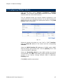
3.2 Configuring Multiple Subnets
From the left menu, select “System > Configure > Multiple
Subnets”. This function allows administrators to setup multiple
subnets within the LAN or DMZ network.
The list displayed shows the various subnets configured in the
system and their corresponding settings. You can edit or delete any
subnet from the list by clicking the appropriate buttons. Click [New
Entry] to add a new subnet.
Fig. 3.5
Select the whether the subnet is in the “LAN” or “DMZ” interface.
Enter the Alias IP address of this subnet and the corresponding
netmask.
Setup the WAN Interface IP addresses of WAN1 and/or WAN2
that the subnet communicates with. Click the [Assist] link to view
a list of the WAN IP addresses.
Select the Forwarding Mode for each WAN interface the subnet
communicates with. NAT mode allows multiple subnet addresses to
connect to the Internet through different WAN IP addresses.
Routing mode
Click [OK] to add the new subnet.
SifoWorks U100 User Manual 1.0
15
Chapter 3: Network Settings
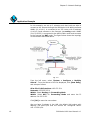
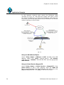
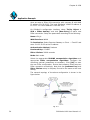
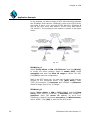
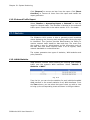
Application Example
In this example, we set up 2 subnets such that both are able to
connect to the Internet through the SifoWorks U100 WAN interfaces.
WAN1 (10.10.10.1) is connected to an ISP router with IP address
10.10.10.2 and connects to the Internet via routing mode. WAN2
(211.22.22.22) is connected to the ADSL/Cable router and connects
to the Internet via NAT mode. The figure below shows the topology
of the network described above.
Fig. 3.6
From the left menu, select “System > Configure > Multiple
Subnet”. From the bottom of the list displayed, click [New Entry]
and setup as follows:
Alias IP of LAN Interface: 162.172.50.1
Netmask: 255.255.255.0
WAN1: Select Routing for Forwarding Mode
WAN2: Select NAT for Forwarding Mode and enter the IP
address 211.22.22.22.
Click [OK] to save the new subnet.
We now have 2 subnets in the LAN, the default LAN subnet with
address 192.168.1.0/24 and the subnet we configured earlier
162.172.50.0/24.
16
SifoWorks U100 User Manual 1.0
Chapter 3: Network Settings
Setup the relevant outgoing Policy rules in “Policy > Outgoing”
such that:
1. All hosts in the default subnet with IP address 192.168.1.xxx can
only access the Internet through the WAN2 interface via NAT mode.
Hosts in this subnet cannot use their private IP to access the
internet via routing mode.
2. All hosts in the second subnet with IP address 162.172.50.xxx
can access the Internet via routing mode through the WAN1
interface. In this mode, the host’s IP address (162.172.50.xxx) is
made public to the Internet servers.
3. All hosts in the second subnet can also access the Internet via
NAT through the WAN2 interface. Here, the internet servers will
only see the WAN2 interface’s IP address.
Please refer to chapter 7, section 7.1 for details on configuring
outgoing policies.
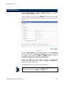
3.3 Route Table
Select “System > Configure > Route Table” to view the list of
static routes configured in the system. From the list, you can edit
or delete the routes by clicking the appropriate buttons.
Fig. 3.7
Click [New Entry] to view the add new static route configuration
interface. Enter the relevant parameters including destination IP,
netmask, default gateway and interface of the static route.
Click [OK] to add the new static route.
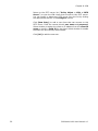
3.4 Setting DHCP
Here you can setup the DHCP server for the LAN and DMZ
interfaces. Select “System > Configure > DHCP” from the left
menu to view the configuration interface.
SifoWorks U100 User Manual 1.0
17
Chapter 3: Network Settings
Fig. 3.8
Select to Enable DHCP Support and enter the Domain Name
where the server is situated.
Enter the IP addresses of the primary and secondary DNS server
and WINS Server. You can also select to automatically get DNS
server’s IP address. The system will use the IP address of the LAN
interface as the address of the primary DNS server.
Specify the Client IP Range used for DHCP lease for the LAN
interface and the DMZ interface separately. You can define up to
2 IP ranges for each of the 2 interfaces.
Note that
1. IP addresses within a range must be in the same subnet.
2. Addresses in Client IP range 2 must be within the same subnet
as Range 1.
3. Client IP range 2 cannot contain the same IP addresses as
Client IP range 1.
Enter the leased time for each IP address lease. The default lease
time is 24 hours. Click [OK] to save the configurations.
18
SifoWorks U100 User Manual 1.0
Chapter 3: Network Settings
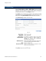
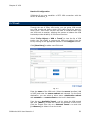
3.5 Dynamic DNS
The dynamic DNS service translates specific domain names to the
corresponding host computer which IP address is not static. Users
can access the host using just the domain name without having to
know the dynamic IP address provided by the computer’s ISP.
From the left menu, select “System > Configure > Dynamic
DNS”. You can setup the use of dynamic DNS (DDNS) servers by
the system through this function.
Click [New Entry] to view the configuration interface as shown in
the figure below:
Fig. 3.9
Select the Service Provider you are registered with. You can click
the [sign up] link to enter the service provider’s website to sign up
for the DDNS service.
Enter the WAN IP address or select to automatically fill in the IP
according to the address of WAN interface selected.
Enter the registered user name, password, and the domain
name of the host. Click [OK] to add the new dynamic DNS.
The icon in the leftmost column of the DDNS list displays the status
of the corresponding DDNS. The icons include:
Update
Successful
SifoWorks U100 User Manual 1.0
Incorrect username
or password
Connecting
to server
Unknown
error
19
Chapter 3: Network Settings
3.6 Host Table
Select “System > Configure > Host Table” to setup mappings
between virtual IP addresses and the host name. The virtual IP
address must be the IP address of SifoWorks’ LAN or DMZ interface.
Internal users will be able to access services on this host using the
virtual IP address mapped to it.
Note: The IP address of the user’s primary DNS server must be the
same as SifoWorks’ LAN port or DMZ Port IP address.
20
SifoWorks U100 User Manual 1.0
4
Chapter
Policy Object Management
In the SifoWorks system, objects refer to the various components
that make up the system's rules. These include addresses, services
as well as address groups and service groups, but exclude the type
of actions (such as permission, prohibition, forwarding, etc.)
specified by rules. An object definition consists of a name, which is
a character string arbitrarily defined by the administrator when it is
created; and its entity, which might be the IP Address, the group of
IP Address, service or service group associated with the defined
object.
Defining an object essentially associates a name that is easier to
remember to an entity or a group of entities. This way, not only
are administrators relieved from remembering all the components,
the process of making rules is also simplified and more intuitive
since security policies can now be managed in an object oriented
perspective.
After objects are defined, you can use them directly in subsequent
rule-making process when defining policies and VPN.
The use of objects allows different pieces of information to be
linked together by a specific object relationship. The linked
information can then be easily managed by referring to a single
object. This concept is useful in a network environment where there
are a large number of IP addresses, different logic working groups,
and different network services. For example, you can define the IP
Address groups of a logic team as a single object even if the groups
are located in different network segments. This way, you can
directly refer to an address object when defining a rule, instead of
entering multiple IP addresses. Also, when the members of the
logic team change, you can modify the object definition rather than
modify the SifoWorks system's policy rules.
This chapter introduces the various objects available in the
SifoWorks system.
SifoWorks U100 User Manual 1.0
21
Chapter 4: Policy Object Management
4.1 Address Objects
The use of address objects allows administrators to associate a
name to IP addresses. These can be the address of a host in the
network or the address of a sub network. Depending on the
network it belongs to, you can define a single LAN IP address, WAN
IP address or a DMZ IP address object.
To further simplify the policy making process, the system also
allows the definition of address groups for each of the 3 networks.
Address groups allow you to group single IP address objects into 1
group object. Therefore, you must first define the necessary single
address objects before defining address groups.
4.1.1 Single Address Objects
LAN Address Objects
From the left menu, select “Policy Object > Address > LAN” to
view the list of address objects for the LAN network. You can
modify or delete the objects by clicking the appropriate button in
the Configure column on the list. Note that the default address
object Inside_Any cannot be edited or deleted.
Click [New Entry] to add a new LAN address object. In the “Add
New Address” interface, enter the name of the object, IP address
and corresponding netmask. You can also enter a specific MAC
address to be mapped to the IP address. You can also select
whether to get a static IP address from the DHCP server.
Tip: Click [Clone MAC Address] for the system to automatically enter
the current user PC’s MAC address.
Click [OK] to add the new address object.
WAN Address Objects
From the left menu, select “Policy Object > Address > WAN” to
view the list of address objects for the WAN network. You can
modify or delete the objects by clicking the appropriate button in
the Configure column on the list. Note that the default address
object Outside_Any cannot be edited or deleted.
Click [New Entry] to add a new WAN address object. In the “Add
New Address” interface, enter the name of the object, IP address
and corresponding netmask.
Click [OK] to add the new address object.
22
SifoWorks U100 User Manual 1.0
Chapter 4: Policy Object Management
DMZ Address Objects
From the left menu, select “Policy Object > Address > DMZ” to
view the list of address objects for the LAN network. You can
modify or delete the objects by clicking the appropriate button in
the Configure column on the list. Note that the default address
object DMZ_Any cannot be edited or deleted.
Click [New Entry] to add a new DMZ address object. In the “Add
New Address” interface, enter the name of the object, IP address
and corresponding netmask. You can also enter a specific MAC
address. You can also select whether to get a static IP address
from the DHCP server.
Click [OK] to add the new address object.
4.1.2 Address Group Objects
From the left menu, select “Policy Object > Address > LAN
Group” to view the list of address group objects for the LAN
network. You can edit or delete any object from the list by clicking
on the appropriate buttons in the configure column.
Click [New Entry] to add a new address group object. Enter the
object’s name. Select the addresses to add into the group from the
left Å-Available address -Æ list and click the [Add >>] button to
add it into the Å- Selected address -Æ list on the right. Select
the addresses from the list on the right and click [<<Remove] to
remove the selected addresses from the group.
Click [OK] to add the new address group.
This configuration interface is similar for all three types of groups
(LAN Group, WAN Group, and DMZ Group).
SifoWorks U100 User Manual 1.0
23
Chapter 4: Policy Object Management
4.2 Service Objects
Service embedded objects are defined by TCP, UDP services
provided in the network.
4.2.1 System Pre-defined Service Objects
SifoWorks U100’s system predefines a number of commonly used
TCP and UDP services such as DNS, HTTP, and LDAP etc. These
services cannot be modified or deleted.
Select “Policy Object > Service > Pre-defined” to view the
details of the pre-defined services which includes the protocol type
and port number of the service.
4.2.2 Custom Service Objects
In addition to pre-defined services, administrators can also define
customized services to suit their needs. Select “Policy Object >
Service > Custom” to view the list of user-defined service objects.
Click [New Entry] to add a new service object. Note that for
custom services, the client port number ranges from 0 to 65535
while the server port number ranges from 0 to 65535.
Fig. 4.1
Enter the service name. Select whether the service uses the “TCP”
protocol, “UDP” protocol or select “other” and specify the protocol
number. Enter the client and server port number range for the
selected protocol. Each service object can use up to 8 protocols,
each with their corresponding client and server port number ranges.
Click [OK] to add the new service object.
24
SifoWorks U100 User Manual 1.0
Chapter 4: Policy Object Management
4.2.3 Service Group Objects
From the left menu, select “Policy Object > Service > Group” to
view the list of service group objects. You can edit or delete any
object from the list by clicking on the appropriate buttons in the
configure column.
Click [New Entry] to add a new service group object. Enter the
object’s name. Select the services to add into the group from the
left <--- Available service ---> list and click the [Add >>]
button to add it into the <--- Selected service ---> list on the
right. Select the services from the list on the right and click
[<<Remove] to remove the selected services from the group.
Click [OK] to add the new service group.
4.3 Schedule Objects
You can define schedule objects to setup schedules when specific
policies are in effect. From the menu, select “Policy Object >
Schedule >Setting” to view a list of schedules.
Click [New Entry] to add a new schedule. Enter the schedule
name and specify the time period for each day of the week the
schedule is set to take effect. Click [OK] to save the new schedule.
Note that schedule objects will only take effect when used in policy
definitions. Please refer to Chapter 6 for details on managing
policies.
Application Example
In this example, we want to configure SifoWorks such that LAN
users can only access the FTP servers between 9am to 5pm on
weekdays.
Select “Policy Object > Schedule > Setting” and click [New
Entry] to add a new schedule. Enter “FTP Access” for schedule
name. Select Start Time as “09:00” and End Time “17:00” for
Monday to Friday. Click [OK] to save the new schedule.
Select “Policy > Outgoing” and click [New Entry] to add a new
outgoing policy. In the Schedule field of the “Add New Policy”
interface, select the “FTP Access” schedule object. Select “FTP” for
Service. Click [OK] to save the new policy. Please refer to chapter
7, section 7.1 for details on configuring outgoing policies.
SifoWorks U100 User Manual 1.0
25
Chapter 4: Policy Object Management
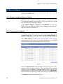
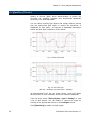
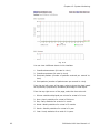
4.4 Quality of Service
Quality of Service (QoS) allows administrators to control the
incoming and outgoing upstream and downstream bandwidth
according to the WAN bandwidth.
You can define multiple QoS objects and assign different policies
with the appropriate QoS object to control the distribution of
bandwidth for that policy. An example of bandwidth distribution
before and after QoS is applied is shown below:
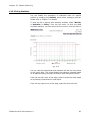
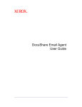
Fig. 4.2 Flow before QoS
Fig. 4.3 Flow after QoS
(Max bw = 400Kbps, Guaranteed bw = 200Kbps)
As demonstrated from the two charts above, using QoS allows
administrators to more efficiently utilize the network’s bandwidth.
From the menu, select “Policy Object > QoS > Setting” to view
a list of QoS objects. You can modify or remove the object by
clicking on the appropriate buttons in the configure column.
Click [New Entry] to add a new QoS object.
26
SifoWorks U100 User Manual 1.0
Chapter 4: Policy Object Management
Enter the name of the QoS object and configure the maximum and
guaranteed bandwidth for the downstream and upstream
bandwidth of WAN1 and WAN2 (if WAN2 is enabled). You should
configure the bandwidth according the bandwidth provided by the
connected ISP.
Set the QoS priority and click [OK] to save the new object.
Note that you must assign QoS objects to policies for the QoS
settings to be effective.
4.5 Content Blocking Objects
You can setup policies to allow or block specific contents from the
network through the use of content blocking objects. These include
filtering based on URL, download file types, instant messaging etc.
You must enable content blocking when defining policies to
activate the use of these content blocking objects.
4.5.1 URL
Select “Policy Object > Content Blocking > URL” to view a list
of content blocking URL defined in the system. You can modify or
delete URL objects by clicking the appropriate button in the
configure column.
Click [New Entry] and enter the URL string. To restrict a
particular URL, enter either the complete domain name or the
keyword of the website. To allow a particular URL, add the symbol
“~” before the domain name or keyword.
Click [OK] to save the new object.
SifoWorks U100 supports the use of the “*” meta-character in the
URL string. That is, a URL string “www.gov.*” will match all URLs
beginning with the string “www.gov.”. An object with the URL
string as “*” only will match all URLs. Such an object represents a
“forbid all” URL content filter.
Note that when a policy is enabled with content blocking, the
system matches the URL to the URL objects in a top-down fashion.
Hence, the forbid all (“*”) object must always be the last object in
the list.
For example, the URL list has 2 objects, “*” and
“~www.google.com”. The system attempts to connect to URL
“www.google.com”.
Case 1: “~www.google.com” is above “*” on the list. The system
will match the URL it is attempting to access with the URL object
SifoWorks U100 User Manual 1.0
27
Chapter 4: Policy Object Management
list in a top down manner. Hence, it matches the URL with the
object “~www.google.com” and therefore, grants the access. The
matching mechanism stops.
Case 2: “*” is above “~www.google.com” in the list. In a similar
top down fashion, the system attempts to match “*” with
“www.google.com”. This returns a match and the system will now
forbid the access since “*” represents forbid all URLs.
4.5.2 Script
Select “Policy Object > Content Blocking > Script”. You can
specify whether to block the use of specific scripts when accessing
the Internet. These include Popup, Java, ActiveX and Cookie
scripts. Click [OK] to save the configuration.
4.5.3 Peer-to-Peer Application
Select “Content Blocking > P2P”. Here, you can select to block
the use of the P2P applications such as Bittorrent, eDonkey etc.
After selection, click [OK] to save the configuration.
4.5.4 Instant Messengers
Select “Content Blocking > IM”. Here you can select to block the
use of instant messaging applications such as MSN, Yahoo
Messenger etc. After selection, click [OK] to save the configuration.
4.5.5 Download Files
Select “Content Blocking > Download”. This function allows you
to block the downloading of certain file types via the HTTP protocol.
You can select the desired file extension from the list. Select All
Types to block the download of all file types. You can also select
audio and video types to block the download of audio or video
files via HTTP.
Click [OK] to save the configuration.
4.5.6 Upload Files
Select “Content Blocking > Upload”. Similar to the download
blocking object, this function allows you to block the uploading of
certain file types via the HTTP protocol. Select the desired file
extension from the list or click all types to block the uploading of
all files.
Click [OK] to save the configuration.
28
SifoWorks U100 User Manual 1.0
5
Chapter
Authentication
In the authentication function group, you can setup basic
authentication settings, authentication server settings and
authentication users. Both internal and remote users can be setup
to require authentication before he can access the Internet.
To activate the use of the authentication user and user group
objects defined here, they must be used in firewall policies and VPN
connections.
5.1 Internal Authentication Server Settings
Select “Policy Object > Authentication > Auth Setting” to
enter the configuration interface. Here, you can setup manage
SifoWorks U100’s authentication settings including the parameters:
Authentication Port: Port number used for the authentication
server
Re-login if Idle: The idle time after which an authenticated user is
required to re-login.
Re-login after user login successfully: The system will require
the user to re-login when this amount of time has passed since the
user was last authenticated.
Disallow re-login if the auth user has login: Select this to not
forcefully re-login an authenticated user.
URL to redirect when authentication succeed: Enter the URL to
redirect the user to upon successful authentication.
Message to display when user login: Enter the message to
display to the user at the login page.
Click [OK] to save the configuration.
SifoWorks U100 User Manual 1.0
29
Chapter 5: Authentication
5.2 Using an External RADIUS Server
SifoWorks also allows administrator to use an external RADIUS
server as the authentication server. Users will need to be
authenticated through the external RADIUS server before he is
allowed access to the Internet. You should setup your external
RADIUS server accordingly.
Select “Policy Object > Authentication > RADIUS”. Enable
RADIUS server authentication and enter the server IP address
and port. Enter the shared secret key for the authentication
between SifoWorks U100 and the RADIUS server.
Select whether to enable the use of the external RADIUS server via
a wireless network.
Click [OK] to save the configuration.
Application Example
In this example, we use an external RADIUS server with IP
172.168.30.12 and port number 1812.
Setup your RADIUS server and RADIUS users accordingly.
Select “Policy Object > Authentication > RADIUS” and enter
the RADIUS server’s information accordingly.
Select “Policy Object > Authentication > Auth Group”. Add a
new authentication user group with the name “Radius”
representing all authentication users of the RADIUS server. From
the <--- Available Authentication User ---> list, select “(Radius
User)” and click [Add>>] to add the RADIUS users to the group.
Select “Policy > Outgoing” and add a new outgoing policy. In the
Authentication User field, select the user group “Radius” defined
above from the drop down menu. Click [OK] to add the outgoing
policy.
When a radius user attempts to access the Internet through a web
browser, the browser will display an Authentication page,
prompting the user for his user name and password. The user
can only access the Internet after he is successfully authenticated
by the RADIUS server.
30
SifoWorks U100 User Manual 1.0
Chapter 5: Authentication
5.3 Using an External POP3 Server
You can also setup a POP3 authentication server as the external
authentication server. Users will need to be authenticated through
the external POP3 server before he is allowed access to the Internet.
Select “Policy Object > Authentication > POP3”. Enable POP3
server authentication and enter the server IP address or
domain name and server port. Click [OK] to save the
configuration.
5.4 Authentication Users
You must setup the users who are required to be authenticated by
the authentication servers for use in the formulation of firewall
policies and VPN connections.
Select “Policy Object > Authentication > Auth User” to view
the list of authentication user objects already defined in the system.
You can modify or delete an object from the list by clicking on the
appropriate buttons in the configure column.
Click [New Entry] to add a new authentication user. Enter the
authentication user name and password. Retype the password to
confirm and click [OK] to save the new authentication user.
Note: If an external RADIUS server is to be used, please add the
authentication users directly on your RADIUS server.
When authentication users (internal/remote) attempt to access
external websites, they will be automatically redirected to the login
page where they can enter their authentication information. Upon
successful authentication, their web browser will be automatically
redirected to the website they were attempting to access.
SifoWorks U100 User Manual 1.0
31
Chapter 5: Authentication
5.5 Authentication User Groups
You can also group the authentication users into user groups for
easier management. Select “Policy Object > Authentication >
Auth Group” to view a list of authentication user group objects in
the system. You can modify or delete an object from the list by
clicking on the appropriate buttons in the configure column.
Click [New Entry] to add a new user group. Enter the group name
and select the authentication users to add into the group from the
<--- Available Authentication User ---> list. Click [Add>>] to
move the selected users into the <--- Selected Authentication
User ---> list. Note that “(Radius User)” refer to users defined on
the external RADIUS server and “(POP3 User)” refer to users on the
external POP3 server.
Click [OK] to add the new authentication user group.
32
SifoWorks U100 User Manual 1.0
6
Chapter
Virtual Service
The IP addresses provided by the ISP are frequently not sufficient
for an enterprise’s entire network. Therefore an enterprise usually
assigns a private IP address to each host and server in its network
and uses the network address translation (NAT) function to route
the addresses to the actual physical IP address. Private IP
addresses are also favored as enterprises do not want to allow
direct external accesses to its internal servers for security reasons.
SifoWorks U100 virtual server achieves this requirement. The actual
IP address of the system’s WAN interface is set as the virtual
server’s IP address. SifoWorks then translates this public IP address
into the private IP address of the server in the LAN network. Note
that virtual server objects defined are only effective when added in
access policies.
6.1 Mapped IP
Here, you can setup the private LAN IP address to map the public
WAN interface IP address to. External users connect to SifoWorks’
WAN interface via the public IP address. The system then uses the
configuration in this function to map the connection to the LAN’s
private IP address.
Select “Policy Object > Virtual Server > Mapped IP”. From the
list, you can edit or delete any mapped IP object by clicking on the
appropriate buttons in the configure column.
Click [New Entry] to add a new mapping. Select the WAN
interface and enter the public WAN IP address accessible by
external users. You can click the [Assist] link for a list of WAN IP
addresses available for the selected interface. Enter the private LAN
IP address to map to and click [OK] to save the new mapping.
SifoWorks U100 User Manual 1.0
33
Chapter 6: Virtual Service
Application Example
In this example, external users access the SifoWorks’ WAN
interface (61.11.11.11). We setup the system such that it maps
this public IP address to a private LAN IP address (192.168.1.10)
from which the FTP and Web services can be accessed. The desired
network topology is shown below:
Fig. 6.1
Setup a LAN Address Object
Select “Policy Object > Address > LAN” and add a new LAN
address object with name “Internal_Server”, IP address
“192.168.1.10”, netmask “255.255.255.255” and the appropriate
MAC address.
Setup a Virtual Service Mapped IP
Select “Policy Object > Virtual Service > Mapped IP”. Click
[New Entry] to add a new mapping. Enter the WAN IP
(61.11.11.11) and enter the LAN IP address (192.168.1.10) in the
Map to Virtual IP field. Click [OK] to add the new object.
34
SifoWorks U100 User Manual 1.0
Chapter 6: Virtual Service
Services
Select “Policy Object > Service > Group” and add a new service
group for FTP and Web services (“Main_Service”). Select the
services “DNS”, “FTP” and all Web based services such as “HTTP” as
the group members. Click [OK] to add the service group.
Setting up the Policies
Select “Policy > Incoming” and add an incoming policy to enable
the mapping of incoming traffic from the public WAN IP address to
the private LAN IP address. The configuration for the policy is as
follows:
Source Address: Outside_Any
Destination Address: Internal_Server (the Virtual service Mapped
IP object defined earlier)
Service: Main_Service
Action: Permit
External users will now be able to access the internal FTP and Web
servers on the LAN (192.168.1.100) subnet using the public IP
address.
6.2 One-to-Many Virtual Server Mappings
Using the virtual service function, administrators can also setup
such that a single public IP address can be mapped to up to four
different LAN network servers providing the same service. Using
this one-to-many capability, the virtual server can balance the
network load between up to four internal servers providing the
same service. This reduces the load on a single server and
introduces redundancy into the system.
Select “Policy Object > Virtual Service > Server 1”. From the
top of the list, click [click here to configure] to setup the public
WAN IP address for this virtual server. Click [New Entry] to setup
the private server providing the service.
SifoWorks U100 User Manual 1.0
35
Chapter 6: Virtual Service
Fig. 6.2
Select the service to be provided by this server. Please refer to
chapter 4, section 4.2 on setting up service objects.
Specify the external service port number that is made public to
the external users. Specify the IP addresses of up to 4 internal
load balance servers.
Click [OK] to save this virtual service object.
Tip: From the “Policy Object > Virtual Service” sub menu, you can
map up to 4 public WAN IP addresses (by choosing “server1” to
“server4”) to the private IP addresses of the internal servers. Note that
each “server” menu option can only be configured with 1 public WAN IP
address.
The virtual servers configured here will only be effective if used
when specifying the source or destination addresses in policies.
Please refer to Chapter 7 for details on policy management.
36
SifoWorks U100 User Manual 1.0
7
Chapter
Firewall Policy Management
The firewall policy management system is one of the core functions
of the SifoWorks U100 security gateway device. All data packets in
the network (other than VPN packets) are matched with the policies
defined in the system. A data packet is permitted as long as it
matches one policy with the permit action.
You can setup different policies based on the inbound and outbound
networks of the traffic. As policy objects are used to configure the
policies, you must first add the objects. Please refer to Chapter 4
and Chapter 5 for object configuration details.
7.1 Outgoing Policies
Outgoing policies are used when the source IP is in the LAN
network while the destination is in the WAN network.
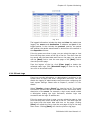
Select “Policy > Outgoing” to view the list of outgoing policies
defined in the system. You can modify or delete policies from the
list by clicking the appropriate buttons in the configure column.
Click the [Pause] button to temporarily pause the use of the
corresponding policy.
Action Column
The Action column in the list displays the action performed on the
data packets matching the policy.
Permit
packets on
all WAN
interfaces
SifoWorks U100 User Manual 1.0
Only permit
packets on
the WAN1
interface
Only permit
outgoing packets
on the WAN2
interface
Deny packets
that matches
the policy
37
Chapter 7: Firewall Policy Management
Option Column
Administrators can enable various options such as enable traffic log,
content blocking etc. when defining policies. The Options column
in the list shows the options that are enabled for each policy.
Traffic Log
Statistics
Authentication User
Schedule
Content Blocking
QoS
IDP
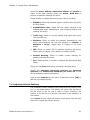
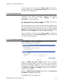
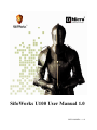
7.1.1 Adding Outgoing Policies
Click [New Entry] to add a new outgoing policy.
Fig. 7.1
38
SifoWorks U100 User Manual 1.0
Chapter 7: Firewall Policy Management
Select the source address, destination address and service to
match to the data packets. Select the Action, WAN Port to
perform on packets matching this policy.
Select whether to enable the various policy options including
1. Schedule: Select the schedule object to specify when the policy
will be in effect.
2. Authentication User: Select the user object required to be
authenticated when attempting to send outgoing packets that
matches this policy.
3. Traffic Log: Select to log the packets that match this policy
into the traffic log.
4. Statistics: Select to collect the statistics generated by this
policy. Administrators can view the statistics in “Monitor >
Statistics > Policy”. Please refer to Chapter 12 for more
details.
5. IDP: Select to enable IDP for packets matching this policy.
Please refer to Chapter 10 for details on configuring IDP.
6. Content Blocking: Select to enable content blocking for
packets matching this policy.
7. QoS: Enable quality of service by selecting the appropriate QoS
object.
Select the VPN trunk that will be monitored using this policy.
Specify the maximum concurrent sessions and maximum
upstream and downstream bandwidth per source IP for the
source addresses matching this policy.
Enter a brief comment for this policy if desired and click [OK] to
add the new outgoing policy.
7.1.2 Adjusting Policies’ Positions
The SifoWorks system matches each packet with the policies in the
list in a top down fashion. The system will check from the first to
the last policy in the list until a match is found. Therefore, the
position of the policies is of utmost importance to the operation of
the firewall.
In the move column, select the position of the policy from the drop
down list to adjust the policies’ priority.
SifoWorks U100 User Manual 1.0
39
Chapter 7: Firewall Policy Management
7.2 Incoming Policies
Incoming policies are used when the source IP is in the WAN
network while the destination is in the LAN network.
Select “Policy > Incoming” to view the list of incoming policies
defined in the system. You can modify or delete policies from the
list by clicking the appropriate buttons in the configure column.
Click the [Pause] button to temporarily pause the use of the
corresponding policy.
Action Column
The Action column in the list displays the action performed on the
data packets matching the policy.
Permit packets on all
WAN interfaces
Deny packets that
matches the policy
Option Column
Administrators can enable various options such as enable traffic log,
content blocking etc. when defining policies. The Options column
in the list shows the options that are enabled for each policy.
Traffic Log
Statistics
Schedule
Network Address Translation
QoS
IDP
40
SifoWorks U100 User Manual 1.0
Chapter 7: Firewall Policy Management
7.2.1 Adding Incoming Policies
Click [New Entry] to add a new incoming policy.
Fig. 7.2
Select the source address, destination address and service to
match to the data packets. Select the Action to perform on packets
matching this policy.
Select whether to enable the various policy options including
1. Schedule: Select the schedule object to specify when the policy
will be in effect.
2. Traffic Log: Select to log the packets that match this policy
into the traffic log.
3. Statistics: Select to collect the statistics generated by this
policy. Administrators can view the statistics in “Monitor >
Statistics > Policy”. Please refer to Chapter 12 for more
details.
4. IDP: Select to enable IDP for packets matching this policy.
Please refer to Chapter 10 for details on configuring IDP.
5. QoS: Enable quality of service by selecting the appropriate QoS
object.
SifoWorks U100 User Manual 1.0
41
Chapter 7: Firewall Policy Management
6. NAT: Select to enable network address translation
Select the VPN trunk that will be monitored using this policy.
Specify the maximum concurrent sessions and maximum
upstream and downstream bandwidth per source IP for the
source addresses matching this policy.
Enter a brief comment for this policy if desired and click [OK] to
add the new incoming policy.
7.2.2 Adjusting Policies’ Positions
The SifoWorks system matches each packet with the policies in the
list in a top down fashion. The system will check from the first to
the last policy in the list until a match is found. Therefore, the
position of the policies is of utmost importance to the operation of
the firewall.
In the move column, select the position of the policy from the drop
down list to adjust the policies’ priority.
7.3 WAN to DMZ Policies
WAN to DMZ policies are used when the source IP is in the WAN
network while the destination is in DMZ. This is used when external
users access configured virtual service, mapped IP services etc.
Select “Policy > WAN to DMZ” to view the list of WAN to DMZ
policies defined in the system. You can modify or delete policies
from the list by clicking the appropriate buttons in the configure
column. Click the [Pause] button to temporarily pause the use of
the corresponding policy.
The configuration procedure for WAN to DMZ policies is identical to
the configuration for incoming policies. Please refer to section 7.2
for configuration details.
42
SifoWorks U100 User Manual 1.0
Chapter 7: Firewall Policy Management
7.4 LAN to DMZ Policies
LAN to DMZ policies are used when the source IP is in LAN while
the destination is in DMZ.
Select “Policy > LAN to DMZ” to view the list of LAN to DMZ
policies defined in the system. You can modify or delete policies
from the list by clicking the appropriate buttons in the configure
column. Click the [Pause] button to temporarily pause the use of
the corresponding policy.
Action Column
The Action column in the list displays the action performed on the
data packets matching the policy.
Permit packets on all
network interfaces
Deny packets that
matches the policy
Option Column
Administrators can enable various options such as enable traffic log,
content blocking etc. when defining policies. The Options column
in the list shows the options that are enabled for each policy.
Traffic Log
Statistics
Schedule
Network Address Translation
IDP
SifoWorks U100 User Manual 1.0
43
Chapter 7: Firewall Policy Management
7.4.1 Adding LAN to DMZ Policies
Click [New Entry] to add a new LAN to DMZ policy.
Fig. 7.3
Select the source address, destination address and service to
match to the data packets. Select the Action to perform on packets
matching this policy.
Select whether to enable the various policy options including
1. Schedule: Select the schedule object to specify when the policy
will be in effect.
2. Traffic Log: Select to log the packets that match this policy
into the traffic log.
3. Statistics: Select to collect the statistics generated by this
policy. Administrators can view the statistics in “Monitor >
Statistics > Policy”. Please refer to Chapter 12 for more
details.
4. IDP: Select to enable IDP for packets matching this policy.
Please refer to Chapter 10 for details on configuring IDP.
5. NAT: Select to enable network address translation
Specify the maximum concurrent sessions for the source
addresses matching this policy.
Enter a brief comment for this policy if desired and click [OK] to
add the new LAN to DMZ policy.
44
SifoWorks U100 User Manual 1.0
Chapter 7: Firewall Policy Management
7.4.2 Adjusting Policies’ Positions
The SifoWorks system matches each packet with the policies in the
list in a top down fashion. The system will check from the first to
the last policy in the list until a match is found. Therefore, the
position of the policies is of utmost importance to the operation of
the firewall.
In the move column, select the position of the policy from the drop
down list to adjust the policies’ priority.
7.5 DMZ to WAN Policies
DMZ to WAN policies are used when the source IP is in the DMZ
network while the destination is in WAN.
Select “Policy > DMZ to WAN” to view the list of DMZ to WAN
policies defined in the system. You can modify or delete policies
from the list by clicking the appropriate buttons in the configure
column. Click the [Pause] button to temporarily pause the use of
the corresponding policy.
The configuration procedure for DMZ to WAN policies is identical to
the configuration for outgoing policies. Please refer to section 7.1
for configuration details.
7.6 DMZ to LAN Policies
DMZ to LAN policies are used when the source IP is in the DMZ
network while the destination is in LAN.
Select “Policy > DMZ to LAN” to view the list of DMZ to LAN
policies defined in the system. You can modify or delete policies
from the list by clicking the appropriate buttons in the configure
column. Click the [Pause] button to temporarily pause the use of
the corresponding policy.
The configuration procedure for DMZ to LAN policies is identical to
the configuration for LAN to DMZ policies. Please refer to section
7.4 for configuration details.
SifoWorks U100 User Manual 1.0
45
Chapter 7: Firewall Policy Management
7.7 Application Examples
Here we list a number of examples for the application of firewall
policies.
7.7.1 Example 1 – Monitoring the Activities of Internal Users
Here we setup a policy to monitor the network activities of internal
users. Select “Policy > Outgoing” and click [New Entry] to add
a new outgoing policy. Configure the policy as follows:
Source Address: Inside_Any
Destination Address: Outside_Any
Action: Permit All
Select to enable Traffic Log and Statistics.
Click [OK] to add the new policy.
Results of Configuration
The system will now record all outgoing activities from LAN users.
Administrators can view this log by selecting “Monitor > Log >
Traffic” from the menu.
Select “Monitor > Statistics > Policy” to view the statistics
generated by the policy.
46
SifoWorks U100 User Manual 1.0
Chapter 7: Firewall Policy Management
7.7.2 Example 2 – Restrict Access to Specific WAN IP; Access to Any Other IP
Addresses Require User Authentication
In this example, we setup the system such that LAN users cannot
access the WAN IP “165.13.32.21/32” and “203.123.24.3/32”. LAN
users “User1”, “User2” and “User3” must be authenticated before
they can access all other addresses on the Internet.
Setup Address Object
Select “Policy Object > Address > WAN” to add new WAN
address objects. Add two WAN address objects with the above IP
address and netmask.
Select “Policy Object > WAN Group” to add a new WAN address
group object “Restrict_WAN_Group”. Select the two WAN address
objects added previously and add them into the group.
Setup Authentication User
Select “Policy Object > Authentication > Auth User” and add
the 3 authentication users, User1, User2 and User3.
Select “Policy Object > Authentication > Auth Group” to add a
new
authentication
user
group
with
the
name
“Restrict_Auth_Group”. Select the 3 authentication users added
above as the members of this group.
Select “Policy Object > Authentication > Setting” to setup the
system authentication server as appropriate.
Define the 1st Outgoing Policy – Restrict WAN IP Access
Select “Policy > Outgoing” and add a new outgoing policy.
Configure the policy as follows:
Source Address: Inside_Any
Destination Address: Restrict_WAN_Group (the WAN address
group object setup above)
Action: Deny All
Click [OK] to save the new policy.
Define the 2nd Outgoing Policy – Authentication
Select “Policy > Outgoing” and add a new outgoing policy.
Configure the policy as follows:
Source Address: Inside_Any
Destination Address: Outside_Any
SifoWorks U100 User Manual 1.0
47
Chapter 7: Firewall Policy Management
Action: Permit All
Authentication User: “Restrict_Auth_Group” (the authentication
group object setup above)
Click [OK] to add the new policy.
Results of the Configuration
2 new policies will be added in the policy list. The system will check
packets based on the priority in which the policy was added. Hence,
each packet will first be checked if its destination address is either
“165.13.32.21/32” or “203.123.24.3/32”. The packet will be
discarded if the address matches.
If not, the system will match the packet against the next policy in
the list. If the packet comes from User1, User2 or User3, the 2nd
policy will be matched successfully and the system will prompt the
user for authentication before granting access.
48
SifoWorks U100 User Manual 1.0
Chapter 7: Firewall Policy Management
7.7.3 Example 3 – Setup a Mail Server in DMZ Accessible by LAN and WAN Users
In this example, we setup the system to allow both LAN and WAN
users to a Mail Server located in DMZ. The address of the mail
server is 60.12.11.11. Users must be able to both send and receive
mail from the mail server.
Setup Mail Server Address Object
Select “Policy Object > Address > DMZ” and add a new DMZ
address object (“Mail_Server”) with the mail server’s IP address
60.12.11.11/32.
Setup Service Object
Select “Policy Object > Service > Group” and add new service
group object with the name “E-Mail”. Select the pre-defined
services “DNS”, “POP3” and “SMTP” as the group members.
Setup Policies for WAN Users
Setup a policy to allow WAN users to send mail to the mail server.
Select “Policy > WAN to DMZ” and add a new policy under this
category with the following configuration:
Source Address: Outside_Any
Destination Address: Mail_Server
Service: E-Mail
Action: Permit
Click [OK] to save the new policy. Next, setup a policy to allow
WAN users to receive mail from the mail server. Select “Policy >
DMZ to WAN” and add a new policy with the following
configuration:
Source Address: Mail_Server
Destination Address: Outside_Any
Service: E-Mail
Action: Permit
Click [OK] to save the new policy.
Setup Policies for LAN Users
Setup a policy to allow LAN users to send mail to the mail server.
Select “Policy > LAN to DMZ” policy and add a new policy with
the following configuration:
Source Address: Inside_Any
SifoWorks U100 User Manual 1.0
49
Chapter 7: Firewall Policy Management
Destination Address: Mail_Server
Service: E-Mail
Action: Permit
Click [OK] to save the new policy. Next, setup a policy to allow LAN
users to receive mail from the mail server. Select “Policy > DMZ
to LAN” and add a new policy with the following configuration:
Source Address: Mail_Server
Destination Address: Inside_Any
Service: E-Mail
Action: Permit
Click [OK] to save the new policy.
Results of the Configuration
Both LAN and WAN users can now send and receive mail from the
internal DMZ mail server.
50
SifoWorks U100 User Manual 1.0
8
Chapter
VPN
On the SifoWorks U100 system, you can setup a IPSec based
virtual private network (VPN) to provide users with secured remote
access into the LAN.
As external users need to be authenticated before they are allowed
remote access into the LAN, you must have configured the
authentication server on the SifoWorks system. Please refer to
Chapter 5 for details on configuring the authentication servers.
8.1 IPSec AutoKey
To create a VPN connection, the system administrator must first
setup IPSec Autokey. The autokey IKE (Internet Key Exchange)
protocol provides a method of negotiating the keys to setup a
secured VPN tunnel between 2 security gateways.
Select “Policy Object > VPN > IPSec Autokey” to view the list
of IPSec autokeys in the system. You can modify or edit an IPSec
object by clicking the appropriate buttons in the configure column.
Click [Connect] to establish a VPN connection with the destination
gateway. Click [Disconnect] to disconnect an established VPN
connection.
Click [New Entry] to add a new autokey. The first half of the
configuration interface consists of essential fields.
SifoWorks U100 User Manual 1.0
51
Chapter 8: VPN
Fig. 8.1
Setup the parameters as follows:
Name:
52
Name of this autokey
WAN Interface:
The WAN interface used for VPN traffic
To Destination:
IP address of the destination gateway. You
can either select whether the gateway has
a fixed IP or domain name or a dynamic
IP.
Authentication
Method:
Select the authentication method between
the two gateways
Preshared Key:
Preshared key between SifoWorks and
remote gateway. The preshared
configured on both gateways must be
same for the VPN connection to
established
Encapsulation/
ISAKMP:
Select the algorithms used to encapsulate
the data transferred during the setup of
security associations (SA) between the two
gateways. Note that the Group selected
must be identical for both gateways
Encapsulation/
IPSec
Algorithm:
Select the algorithms used to encapsulate
the data transferred during the IPSec
tunnel setup. You can select whether to
encapsulate both authentication and normal
data traffic or only authentication data.
the
key
the
be
SifoWorks U100 User Manual 1.0
Chapter 8: VPN
You can continue to configure the optional parameters of the
autokey as follows:
Fig. 8.2
Perfect Forward
Secrecy:
ISAKMP Lifetime:
IPSec Lifetime:
Mode:
Select PFS for encryption
Specify the security association lifetime
Specify the IPSec lifetime
Select whether to use main or aggressive
mode to negotiate SA
My ID:
Identifying name for the local system
Peer ID:
Identifying name for the remote peer
GRE/IPSec:
Manual Connect:
Dead Peer
Detection:
Enter the local and remote IP addresses
for generic routing encapsulation (GRE)
Select to enable manual VPN connection
Specify the delay and timeout of
sending packets used to detect dead peer
connection.
Click [OK] to save the IPSec autokey.
SifoWorks U100 User Manual 1.0
53
Chapter 8: VPN
Application Example
Here we setup a IPSec VPN connection with company B with WAN
IP address 211.22.22.22. The local SifoWorks’ WAN1 IP address is
61.11.11.11. LAN IP address is 192.168.10.X
On SifoWork’s configuration interface, select “Policy Object >
VPN > IPSec Autokey” and click [New Entry] to add a new
IPSec connection. Setup the parameters according to the following:
Name: VPN_A
WAN Interface: WAN1
To Destination: Select Remote Gateway or Client -- Fixed IP and
enter 211.22.22.22 as the IP address
Authentication Method: Preshare
Preshared Key: 1234567
IPSec Lifetime: 28800 seconds
Mode: Main mode
Select the appropriate ISAKMP encapsulation algorithms and
appropriate IPSec encapsulation algorithms. Configure the
remaining optional parameters as necessary. Click [OK] to save
the new IPSec configuration. Ensure that company B has setup an
IPSec connection accordingly. Note that the preshared key and
IPSec lifetime setup in company B must be the same as the local
setting.
The network topology of the above configuration is shown in the
figure below:
Fig. 8.3
54
SifoWorks U100 User Manual 1.0
Chapter 8: VPN
8.2 PPTP Server
Select “Policy Object > VPN > PPTP Server” to configure
SifoWorks as the PPTP server.
From the top of the list, click [Modify] to edit the basic PPTP
server settings. The configuration interface is shown in the figure
below:
Fig. 8.4
Select to Enable PPTP server. Select whether to use encryption
for this server. Enter the Client IP Range and the IP addresses of
the primary and secondary DNS and WINS servers. Check to
allow PPTP clients to connect to the Internet.
Specify the idle time after which the user is automatically
disconnected. Also specify the number of retry and timeout for
each echo-request packet sent.
Click [OK] to save the PPTP server configuration.
Tip: You can also enable or disable the PPTP server from the top of
the list by clicking on the [enable] or [disable] link.
SifoWorks U100 User Manual 1.0
55
Chapter 8: VPN
Return to the PPTP server list (“Policy Object > VPN > PPTP
Server”) to view the VPN clients that connect to this PPTP server.
You can modify or delete any PPTP server from the list by clicking
the appropriate buttons in the configure column.
Click [New Entry] to add a new client that can connect to this
PPTP server. Enter the remote client’s user name and password.
Select whether to assign the client an IP address from the client IP
range or specify a fixed IP for the client. Select whether to enable
the client can be manually disconnected.
Click [OK] to add the new user.
56
SifoWorks U100 User Manual 1.0
Chapter 8: VPN
8.3 PPTP Client
Select “Policy Object > VPN > PPTP Client”. Here, you setup
the PPTP clients that connect to a remote PPTP server. From the list
displayed, you can modify or remove a PPTP client by clicking on
the appropriate buttons in the configure column.
The uptime column displays the connection time between the PPTP
client and the server. Click [Connect] to connect the client to the
PPTP server. Click [Disconnect] to disconnect from the server.
Click [New Entry] to add a new PPTP client.
Fig. 8.5
User Name:
Password:
Client’s user name
Client’s password
Server IP or
Domain Name:
IP address or domain name of the PPTP
server to connect to. Select whether to
encrypt the address when establishing
connection with the server
WAN Interface:
Select which WAN interface the client uses
to communicate with the remote server
NAT:
Manual Connect:
Select to enable NAT
Select to enable manual connection of the
client to the remote server
Click [OK] to save the new PPTP client.
SifoWorks U100 User Manual 1.0
57
Chapter 8: VPN
Application Example
In this example, we want to setup a PPTP VPN connection between
two SifoWorks U100 devices. SifoWorks_A acts as the PPTP server
with WAN IP 61.11.11.11 and LAN IP 192.168.10.X. SifoWorks_B
acts as the PPTP client with WAN IP 211.22.22.22 and LAN IP
192.168.20.X. The topology of the network is shown in the figure
below:
Fig. 8.6
SifoWorks_A
Select “Policy Object > VPN > PPTP Server” and click [Modify]
to modify the server settings. Select to enable PPTP. Select
encryption and enter the client IP range as 192.44.75.1-254.
Click [OK] to save the configuration.
Back in the PPTP server list, you now have to add a user that can
connect to the configured server. Click [New Entry]. Enter
“PPTP_B_Connection” in Username and “123456” in password.
Select to assign client IP by “IP Range”.
SifoWorks_B
Select “Policy Object > VPN > PPTP Client” and click [New
Entry]. Enter “PPTP_B_Connection” in username and “123456” in
password. Enter the server IP address as 61.11.11.11
(SifoWorks_A WAN IP) and select encryption. For WAN interface,
select “WAN1”. Click [OK] to save the new PPTP client.
58
SifoWorks U100 User Manual 1.0
Chapter 8: VPN
Result of Configuration
SifoWorks_B can now establish a PPTP VPN connection with the
server at SifoWorks_A.
8.4 Trunk
Through the use of IPSec VPN trunks, you can group VPN tunnels
into VPN trunks and define which VPN traffic should be send by
which trunk. VPN trunks can also be used to forward traffic from
one VPN trunk to another, allowing the system to balance the VPN
load and provide reliability of VPN tunnel services.
Select “Policy Object > VPN > Trunk” to view the list of VPN
trunks. You can modify or remove any VPN trunk object from the
list by clicking on the appropriate buttons in the configure column.
Click [New Entry] to add a new VPN trunk.
Fig. 8.7
Enter the name of the VPN trunk. Select the source interface (LAN
or DMZ) and enter the source subnet and netmask. For the trunk
destination, you can select to either enter a destination subnet
and netmask or a remote client as the trunk’s destination.
From the <--- Available Tunnel ---> list, select the VPN tunnels
and click [Add>>] to add the tunnels as members of this trunk.
Click the tunnels from the <--- Selected Tunnel ---> and click
[<<Remove] to delete it from the trunk.
SifoWorks U100 User Manual 1.0
59
Chapter 8: VPN
Enter the keep alive IP address. This address is used to check the
status of the tunnel and should be an existing server’s IP address in
the remote LAN. Select whether to show remote network
neighborhood.
Click [OK] to save the new VPN trunk.
Note: You must setup policies using the added VPN trunks before they
take effect.
60
SifoWorks U100 User Manual 1.0
9
Chapter
Mail Security
SifoWorks U100 system incorporates a function that checks for and
maintains the security of sent and received emails in the network.
Emails will go through anti-spam and anti-virus checks before going
through the mail relay function to forward the mails to the
appropriate mail servers.
9.1 Configuring the Basic Settings
Select “Mail Security > Configure > Setting” to setup the basic
configuration of the mail security function. Specify the maximum
size of mails that should be scanned for spam and viruses. You can
also select whether to add a message to the subject line for
mails that are not scanned. Enter the message to be inserted at the
front of the subject line in the textbox provided.
Click [OK] to save the configuration.
9.2 Mail Relay
After mails are scanned by the SifoWorks system, the system
forwards the mails to their respective mail servers according to the
settings in the mail relay function.
Select “Mail Security > Configure > Mail Relay” to view a list of
mail servers to relay mails to. You can modify or remove any mail
relay server from the list by clicking on the appropriate buttons in
the configure column.
Click [New Entry] to add a new relay server. If the mail server is
located internally (LAN or DMZ), select Domain name of internal
mail server and enter the domain name and IP address of the
mail server. If the mail server is located externally, select allowed
external IP of mail relay and enter the external IP address and
netmask. Click [OK] to add the new mail relay server.
SifoWorks U100 User Manual 1.0
61
Chapter 9: Mail Security
9.3 Anti-Spam
Here you can setup the settings for the anti-spam function.
Filtering spam mails received by the system reduces the burden on
the mail servers and can also increase work efficiency as the users
need not spend time sorting and removing spam mail from his
inbox.
9.3.1 Basic Settings
Select “Mail Security > Anti-Spam > Setting” to configure the
basic anti-spam settings.
In this configuration interface, select to enable anti-spam and
select the network where the mail servers are located. Specify the
threshold score of spam mails and enter the message to add to
the spam mail’s subject line.
Select your desired options for the spam mail check settings.
Tip: Click [Test] to test that the checks are working correctly.
Select the action to perform on the detected spam mails. When the
mail’s recipient is on an internal mail server, you can either delete
the mail, continue to deliver the mail to the recipient or forward
the mail to the specified mail address.
Click [OK] to save the configuration.
62
SifoWorks U100 User Manual 1.0
Chapter 9: Mail Security
9.3.2 Spam Rules
Select “Mail Security > Anti-Spam > Rule”. Here, a list of rules
for the checking of spam mails can be viewed. You can modify or
remove a rule by clicking the appropriate buttons in the configure
column.
To add a new rule, click [New Entry] from the bottom of the list.
Fig. 9.1
Enter the rule name and comments if any. Select the whether to
classify mails that matches this rule as “spam” mails or “ham”
mails. Also select whether to enable auto-training for the system
to automatically learn the classification of mails matching this rule.
Auto-training will take place at the scheduled time daily. Please
refer to section 9.3.5 for details.
Select the action to take on the mails matching the rule. If the
action “forward to” is selected, you must also enter the email
address to forward the mail to in the adjacent textbox.
Within a single rule, you can add multiple matching patterns. The
list below displays the criteria that are matched to mails by this rule.
Specify the item of the mail to check and the pattern to check
against. Select the condition of the check and click [Next Row]
to add the new criteria into the list. Note that the conditions
available for selection differ according to the check item. Click
[Remove] to delete a criteria from the list.
When “And” is selected in the combination field, only mails
matching every criteria in the list will match this rule. If “Or” is
selected, a mail matches the rule as long as it fulfils one of the
criteria in the list.
Click [OK] to add the new rule.
Note: System spam rules take priority over the email whitelist and
blacklist.
SifoWorks U100 User Manual 1.0
63
Chapter 9: Mail Security
9.3.3 Email Address Whitelist
You can setup a list of email addresses such that mails from these
addresses are sent to the recipient without having to be checked by
the anti-spam function.
Select “Mail Security > Anti-Spam > Whitelist” to view the list
of allowed email addresses. You can modify or remove an address
from the list by clicking the appropriate buttons in the configure
column.
Click [New Entry] to add a new allowed email address. Enter the
whitelist email address. You can either input the entire email
address (such as “[email protected]”) or use the wildcard
character “*”. For example “*yahoo*” will represent all email
addresses containing the word “yahoo”.
In the direction field, select whether the email address is to
correspond to the mail’s sending email (“from”) or recipient email
(“To”). Lastly, enable or disable auto-training for the system to
automatically learn that mails with this email address are classified
as “ham” (non-spam) mail. Auto-training will take place at the
scheduled time daily. Please refer to section 9.3.5 for details.
Click [OK] to add the new allowed email address.
Export Whitelist to Client
You can save the system’s email whitelist to a file stored locally.
Click [Download] to export the list.
Import Whitelist from Client
To import a list of email addresses from a local file into the
SifoWorks U100 system, click [Browse…] and select the file to
upload. Click [OK] to begin the import.
64
SifoWorks U100 User Manual 1.0
Chapter 9: Mail Security
9.3.4 Email Address Blacklist
You can setup a list of email addresses such that mails from these
addresses are automatically blocked by the system.
Select “Mail Security > Anti-Spam > Blacklist” to view the list
of restricted email addresses. You can modify or remove an address
from the list by clicking the appropriate buttons in the configure
column.
Click [New Entry] to add a new restricted email address. Enter the
blacklist email address. You can either input the entire email
address (such as “[email protected]”) or use the wildcard
character “*”. For example “*yahoo*” will represent all email
addresses containing the word “yahoo”.
In the direction field, select whether the email address is to
correspond to the mail’s sending email (“from”) or recipient email
(“To”). Lastly, enable or disable auto-training for the system to
automatically learn that mails with this email address are classified
as “spam” mail. Auto-training will take place at the scheduled time
daily. Please refer to section 9.3.5 for details.
Click [OK] to add the new blacklisted email address.
Export Blacklist to Client
You can save the system’s email blacklist to a file stored locally.
Click [Download] to export the list.
Import Blacklist from Client
To import a list of email addresses from a local file into the
SifoWorks U100 system, click [Browse…] and select the file to
upload. Click [OK] to begin the import.
Note: The email whitelist is of higher priority than the email blacklist. This
means that if the same email address is present in both the whitelist and
blacklist, the email will be classified as “ham” mail.
SifoWorks U100 User Manual 1.0
65
Chapter 9: Mail Security
9.3.5 Automatic System Spam Mail Training
You can setup such that the system can learn from the mails that
have been detected as spam or ham previously. Select “Mail
Security > Training” to configure the settings for system spam
training.
The top part of the interface displays the training statistics
including the number of spam and ham mails in the system
available for training and the free space available for storing mails
for training.
The remaining portion of the interface consists of the training
parameters you can configure.
Fig. 9.2
Training Database
Click [Download] to export the system’s training database into a
file for local storage.
Click [Browse…] and select a database file to import into the
system.
Click [Reset Database] to reset the system database.
66
SifoWorks U100 User Manual 1.0
Chapter 9: Mail Security
Spam Mail for Training
Import a file containing a spam mail that was erroneously judged
as non-spam. This trains the system to recognize the mail as spam
mail in future.
Ham Mail for Training
Import a file containing a ham mail that was erroneously judged as
spam mail. This trains the system to recognize the mail as ham
mail in future.
Note that the training files to be imported can be any data file type
as long as it is in ASCII.
Spam Account for Training
The system can be trained to recognize the spam mails present in a
mail account. Configure the account’s POP3 server domain name,
username and password. You can click [Account Test] to test
the connection of the system to the configured account.
Ham Account for Training
The system can be trained to recognize the ham mails in a mail
account. Configure the account’s POP3 server domain name,
username and password. You can click [Account Test] to test
the connection of the system to the configured account.
Training Time
Here, you can setup a daily schedule for automatic learning to take
place in the system. Select the time to begin updating the training
database per day.
You can also click [Training Now] to manually begin the system
training immediately.
Click [OK] to save the configurations made above and begin
importing the selected files if any.
Note: If the training file was exported from an email software, please close
the e-mail software before importing the file.
SifoWorks U100 User Manual 1.0
67
Chapter 9: Mail Security
9.3.6 Spam Mail Log List
All spam mails detected will be logged in the system regardless of
the action taken. Administrator can select “Mail Security > AntiSpam > Spam Mails” to view the list of spam mails detected and
logged in the system.
Fig. 9.3
The system separates the spam mail log for [Internal] mail
servers and [External] mail servers. Click the respective buttons
on the top right corner of the list to view the mail log list for the
internal or external mail servers.
You can sort the list by recipient email address, total spam mail
and total mail scanned by clicking on the corresponding columns
in the list. An orange arrow next to the column name indicates that
the list is currently sorted by that column. A down arrow indicates
the list is sorted in descending order while an up arrow indicates
ascending order.
68
SifoWorks U100 User Manual 1.0
Chapter 9: Mail Security
9.4 Anti-Virus
SifoWorks U100 further incorporates a function to scan emails sent
to the mail servers for viruses.
Select “Mail Security > Anti-Virus > Setting” to setup the antivirus function’s basic configurations.
Anti-Virus Setting
Fig. 9.4
In this part of the interface, setup the basic settings for the antivirus function. Select the virus scan engine to be used and the
networks where the mail server is in. The SifoWorks U100 antivirus scan can be used on mails in both internal (LAN and DMZ) or
external (WAN) mail servers.
Enter the message to be added to the subject line of the virus
mails detected.
The time the system’s virus definitions were last updated is also
displayed along with the time interval between each update. The
current virus definition file version is also displayed.
Click [Update NOW] to update the system’s virus definitions
immediately. Click [Test] to test the connection between the
system and the update server.
Action of Infected Mail
Here, setup the action to be performed on infected mails that are
detected by the system.
For internal mail servers, you can choose to either delete the
virus mail, deliver the original virus mail to the recipient,
deliver a notification mail instead of the original virus mail to
the recipient or forward the virus mail to the specified email
address.
SifoWorks U100 User Manual 1.0
69
Chapter 9: Mail Security
For external mail servers, you can only choose to either deliver
a notification mail instead of the original virus mail to the
recipient or deliver the original mail to the recipient.
Click [OK] to save the configurations.
9.4.1 Virus Mail Log List
All virus mails detected will be logged in the system regardless of
the action taken. Administrator can select “Mail Security > AntiVirus > Virus Mails” to view the list of virus mails detected and
logged in the system.
The system separates the virus mail log for [Internal] mail servers
and [External] mail servers. Click the respective buttons on the
top right corner of the list to view the mail log list for the internal or
external mail servers.
You can sort the list by recipient email address, total virus mail
and total mail scanned by clicking on the corresponding columns
in the list. An orange arrow next to the column name indicates that
the list is currently sorted by that column. A down arrow indicates
the list is sorted in descending order while an up arrow indicates
ascending order.
Tip: SifoWorks’ anti-virus and anti-spam functions are enabled by
default. The system can scan for virus and spam mails based on default
settings without any administrator configuration.
70
SifoWorks U100 User Manual 1.0
10
Chapter
Intrusion Detection and Prevention
Through SifoWorks’s intrusion detection and prevention (IDP)
functionality, administrator’s can setup the system to detect and
prevent attacks such as SYN attacks, on the network from both
internal and external sources.
10.1 Basic IDP Settings
Select “IDP > Configure > Setting”
configuration for the IDP function.
to setup the basic
Fig. 10.1
The first part of the screen, as shown in the figure above, displays
the information on the IDP signature version and last update
time. Click [Update NOW] to update the IDP signature definitions.
Click [Test] to test the connection of SifoWorks to the update
server.
Select to enable anti-virus checks for the various protocols and
click [OK] to save the configuration.
In the bottom part of the screen, select the default action to
perform on high, medium and low risk attack packets detected.
Also select whether to log the information of the detected packets.
SifoWorks U100 User Manual 1.0
71
Chapter 10: Intrusion Detection and Prevention
10.2 IDP Signatures
Select “IDP > Signature” to manage the IDP signatures used to
detect whether a packet is an attack packet.
10.2.1 Traffic Anomalies
Select “IDP > Signature > Anomaly” to view a list of unusual
network activity such as syn flood, udp flood etc. and the detection
status of such anomalies.
Click [Modify] corresponding to the anomaly to edit.
For “SYN flood”, “UDP flood” and “ICMP flood” attacks, you can
select to enable the detection for such attacks and specify the
maximum threshold of packets from the same source before a
flood attack is detected. Enter the blocking time of the sending IP
of the packets from which a flood is detected. Select the action to
perform on the packets and whether to log the packets’ information.
For all other traffic anomalies, you can only select whether to
enable the detection of such attacks, the action to perform on the
attack packets detected and whether to log the packets’
information.
Click [OK] to save the settings.
10.2.2 Pre-defined IDP Signatures
The SifoWorks U100 system has several pre-defined IDP signatures
used to detect the various attacks. You can update the IDP
signatures by downloading signature definition files into the system.
Please refer to section 10.1 for details.
By default, the system enables the detection of attacks based on all
pre-defined IDP signatures. Select “IDP > Signature > Predefined” to view a list of the IDP signatures and their status. A
partial list is shown in the figure below.
72
SifoWorks U100 User Manual 1.0
Chapter 10: Intrusion Detection and Prevention
Fig. 10.2
The IDP signatures are categorized into various groups including
“Backdoor” attacks, “DDOS” attacks etc. Click the [+] button to
view the list of signatures under each group.
The Risk column shows the risk level of the corresponding attack
(H = high, M = medium, L = low).
Click [Modify] to modify the status of an IDP signature. You can
only edit the action to perform and whether to log the information
of the packets detected to be carrying such an attack.
10.2.3 Self-defined IDP Signatures
Aside from the downloaded pre-defined IDP signatures,
administrators can also define customized signatures to meet their
network’s needs. Select “IDP > Signature > Custom” to view a
list of administrator-defined IDP signatures. You can edit or remove
any signature from the list by clicking on the appropriate buttons in
the configure column.
Click [New Entry] to add a new IDP signature.
Enter the name of the signature and select the protocol of the
packets to be matched to this IDP rule. Enter the source port and
destination port of the packets to be matched. Specify the
signature’s risk level and action to be performed on the packets.
Select to log the packets’ information. Enter the content matching
criteria of the signature. All packets containing this content string
will be matched to the signature and the corresponding action will
be carried out on the packet.
Click [OK] to save the new IDP signature.
SifoWorks U100 User Manual 1.0
73
Chapter 10: Intrusion Detection and Prevention
10.3 IDP Log Report
The system logs the information of all packets matching the
signatures with the log option selected. This facilitates the
monitoring of IDP activities in the network and aids administrators
in maintaining the security of the network.
Select “IDP > IDP Report > Log” to view the list of logs collected
by the system.
Logged information includes the time of occurrence, event
occurred, signature classification, the packet’s incoming interface,
the IP address where the attack originated from, the victim IP
address and port number and the action taken on the packet.
74
SifoWorks U100 User Manual 1.0
11
Chapter
Anomaly Flow IP
Administrators can use the anomaly flow IP function, to block
specific internal IP addresses from which virus or intrusion attacks
are detected to be originating from.
11.1 Basic Settings
Select “Anomaly Flow IP > Setting” to setup the basic settings
of the function.
Anomaly Flow IP Setting
Here, specify the maximum number of sessions per second
allowed for each source IP. When the number of sessions
established per second exceeds this threshold, the IP will be
detected as an anomaly flow IP.
Enable anomaly flow IP blocking and specify the blocking time
in seconds.
Select whether to enable E-mail alert notification and/or
NetBIOS alert when anomaly flow is detected. Specify the IP
address of the administrator if NetBIOS alert notification is
enabled.
Click [OK] to save the configuration.
Non-detected IP
The second half of the interface displays a list of anomaly IP
addresses that will not be checked for anomaly flow. You can
modify or delete an IP address from the list by clicking on the
appropriate buttons in the configure column.
SifoWorks U100 User Manual 1.0
75
Chapter 11: Anomaly Flow IP
Click [New Entry] to add a new IP address. Select the interface
where the IP is located. Enter the IP address and netmask and
click [OK] to save the new IP.
11.2 Anomaly Flow IP Log
The system records the IP on which anomaly flow is detected.
Administrators can view the logged records by selecting “Anomaly
Flow IP > Virus-infected IP” from the left menu.
The logged information includes the interface where the IP
address is located in, the IP address and the time when the alarm
was raised.
76
SifoWorks U100 User Manual 1.0
12
Chapter
System Monitoring
SifoWorks U100 offers a variety of monitoring functions such as log,
reports, statistics etc. to facilitate the task of monitoring and
debugging network events and problems.
12.1 Logs
Administrators can view a list of logs collected by the system by
selecting “Monitor > Log”. Log files aid in the administrator’s task
of debugging errors in the network.
The log files are categorized into 3 groups, traffic logs, event logs
and connection logs.
12.1.1 Traffic Logs
Traffic logs records information regarding all network traffic flow.
Select “Monitor > Log > Traffic” to view a list of the logs
collected by the system. Logging of the traffic packets can be
enabled when defining the system’s policies. Please refer to
Chapter 7 on policy management for details.
SifoWorks U100 User Manual 1.0
77
Chapter 12: System Monitoring
Fig. 12.1
The logged information includes the date and time the packet was
logged, the source and destination IP address and port of the
logged packet. It also includes the protocol used by the packet
and whether the packet was allowed or denied from the network in
the disposition column.
If the log spans more than 1 page, you can select the page to view
from the drop down menu at the top of the list. The menu lists the
log record with the latest date and time on the page. You can also
use the [Next] link to view the next page or the [Back] link to
view the previous page.
From the bottom of the list, click [Clear Logs] to delete the
collected traffic logs. Click [Download Logs] to save the log list
into a file to be stored locally.
12.1.2 Event Logs
Event logs records information on administrator’s activities in the
system such as logins and other configuration activities. You can
enable the logging of administrative activities when configuring the
basic system settings. Please refer to Chapter 2, section 2.1.4 for
details.
Select “Monitor > Log > Event” to view the log list. The logged
information includes the date and time of event occurrence and a
description of the event. For example, a login event would include
a description stating the login username, whether login was
successful and the login IP address etc.
If the log spans more than 1 page, you can select the page to view
from the drop down menu at the top of the list. The menu lists the
log record with the latest date and time on the page. Clicking
[Next] will refresh the list to view the next page of logs in the drop
down menu. Clicking [Back] will view the previous log page.
78
SifoWorks U100 User Manual 1.0
Chapter 12: System Monitoring
From the bottom of the list, click [Clear Logs] to delete the
collected traffic logs. Click [Download Logs] to save the log list
into a file to be stored locally.
12.1.3 Connection Logs
Connection logs records information regarding the
connections on the system. Select “Monitor >
Connection” to view the log list.
network
Log >
The logged information includes the date and time of occurrence
and a description of the connection event.
If the log spans more than 1 page, you can select the page to view
from the drop down menu at the top of the list. The menu lists the
log record with the latest date and time on the page. Clicking
[Next] will refresh the list to view the next page of logs in the drop
down menu. Clicking [Back] will view the previous log page.
From the bottom of the list, click [Clear Logs] to delete the
collected traffic logs. Click [Download Logs] to save the log list
into a file to be stored locally.
12.1.4 Log Backup Settings
Select “Monitor > Log > Log Backup” to setup the automatic log
backup configuration in the system.
Fig. 12.2
Select to enable log mail support. When this is enabled,
SifoWorks will automatically send the log list to the email server
when the log exceeds 300Kbytes in size. The logs will then be
cleared from the system. Setup the email server to send the log to
in “System > Configure > Setting”. Please refer to Chapter 2,
section 2.1.3 for details.
Select to enable syslog messages and specify the syslog host
IP address and port number/range.
Click [OK] to save the configuration.
SifoWorks U100 User Manual 1.0
79
Chapter 12: System Monitoring
12.2 Report
Administrators can view an overall report of the outbound and
inbound traffic through the SifoWorks U100 system. Select
“Monitor > Accounting Report > Setting” to setup the use of
this function.
Here, select the information to be recorded in the report for the
outbound and inbound reports. The selectable parameters include
source IP, destination IP and service accessed.
Click [OK] to save the configuration.
12.2.1 Outbound Traffic Report
Select “Monitor > Accounting Report > Outbound” to view the
overall report generated by the system for all outgoing traffic
through the system.
Fig. 12.3
Select to view the report collected based on source IP,
destination IP or service from the drop down menu. You can sort
the report according to each column by clicking on the column
name. An orange arrow represents that the report is currently
being sorted according to that column. An up arrow indicates
ascending order while a down arrow indicates descending order.
Up to 10 items are displayed per page. You can view the other
items by selecting from the top drop down menu.
The total upstream and downstream statistics for all report items
spanning all pages, is displayed at the bottom of the list.
80
SifoWorks U100 User Manual 1.0
Chapter 12: System Monitoring
Click [Remove] to remove an item from the report. Click [Reset
Counters] to remove all items from the report and restart the
report generation.
12.2.2 Inbound Traffic Report
Select “Monitor > Accounting Report > Inbound” to view the
report for inbound traffic. The interface is identical to the outbound
traffic report. Please refer to the above section 12.2.1 for details.
12.3 Statistics
The SifoWorks U100 system is able to generate overall statistical
charts displaying the incoming and outgoing traffic flowing through
its interfaces. This function provides administrator the ability to
monitor network traffic based on date and time. The chart form
also makes it easy for administrators to find information such as
the date and time when network traffic is at its highest, when
network bandwidth is underutilized etc.
The system generates two types of statistics, WAN statistics and
policy statistics.
12.3.1 WAN Statistics
WAN statistics includes charts showing all incoming and outgoing
traffic over the system’s WAN interfaces. Select “Monitor >
Statistics > WAN”.
Fig. 12.4
From the list, you can view the statistics for each individual enabled
WAN interface or the overall statistics for all WAN interfaces. From
the Time column, you can select the type of chart you wish to view
to bring up the corresponding charts as shown in the figure below.
SifoWorks U100 User Manual 1.0
81
Chapter 12: System Monitoring
Fig. 12.5
You can view 4 different charts in this interface:
1. Interface downstream (bit rate Vs. time)
2. Interface upstream (bit rate Vs. time)
3. Received packets (number of packets received per second Vs.
time)
4. Sent packets (number of packets sent per second Vs. time)
From the top left corner of the page, select to draw the chart based
on bit/second, byte/second, utilization percentage or total bytes.
From the top right corner of the page, select the time axis unit.
1. Minute: statistics displayed per minute for a total of 1 hour
2. Hour: Hourly statistics for a total of 24 hours
3. Day: Daily statistics for a total of 1 month
4. Week: Weekly statistics for a total of 3 months
5. Month: Monthly statistics for a total of 1 year
6. Year: Yearly statistics for a total of 10 years.
82
SifoWorks U100 User Manual 1.0
Chapter 12: System Monitoring
12.3.2 Policy Statistics
You can enable the generation of statistical chart for specific
policies by enabling the statistic option when managing policies.
Please refer to Chapter 7 for details.
To view the list of policies with statistics enabled, select “Monitor
> Statistics > Policy” from the left menu. As with the WAN
interface statistics, you can select the time unit to view the chart in.
Fig. 12.6
You can view the downstream and upstream bit rate Vs. time charts
for the policy here. The charts display the statistics collected based
on all packets flowing through the system that matches the policy.
From the top left corner of the page, select to draw the chart based
on bit/second, byte/second or total bytes.
From the top right corner of the page, select the time axis unit.
SifoWorks U100 User Manual 1.0
83
Chapter 12: System Monitoring
12.4 Wake on LAN
The wake on LAN function provided in SifoWorks allows
administrators to setup the system to remotely boot up specific PCs
located within the connected LAN network.
Select “Monitor > Wake on LAN > Setting” to view a list of LAN
PCs setup to be started up remotely. You can edit or delete any
entry from the list by clicking the appropriate buttons in the
configure column.
Click [New Entry] to add a new LAN PC to be booted up remotely.
Specify the name and the PC’s MAC address. Click [OK] to add
this PC to the list.
12.5 System Status
Administrators can also view the various statuses of the system
from the “monitor” function group. These include the status of the
4 network interface ports, DHCP clients in the system etc.
12.5.1 Status of Network Interface
Select “Monitor > Status > Interface” to view the basic
configuration information and status of the 4 network interfaces
(LAN, WAN1, WAN2, DMZ). This includes the interface’s
forwarding mode, IP and MAC addresses, packets received
and transmitted etc.
On the top of the table you can also view the total number of
active sessions currently established on the system and the total
system up time.
12.5.2 Authentication Users
Select “Monitor > Status > Authentication” to view the list of
authenticated users currently logged onto the system. The list
displays the user’s IP address, user name of the user’s
authentication account and the total login time. You can manually
logout the user by clicking [Remove] in the configure column.
84
SifoWorks U100 User Manual 1.0
Chapter 12: System Monitoring
12.5.3 ARP Table
Select “Monitor > Status > ARP Table” to view the ARP table
stored in the system.
Fig. 12.7
From the top of the list, click [Download] to download the antiARP virus software to protect the ARP table from viruses. You
can click [Comment] to view information on downloading and
executing the anti-virus software.
The total number of ARP entries in the table is shown from the top
of the table.
On the table, you can view the IP address to MAC address
resolution and the interface through which the PC communicates
to the system. You can remove an entry from the table by clicking
the [Remove] button in the configure column.
In the static column, select the IP to MAC address mappings that
are to be kept static from the table. To select all ARP entries as
static, click the checkbox next to the static column name. Click
[OK] to save the changes.
Click [New Entry] to add a new IP to MAC address mapping into
the table. In the page that appears, enter the IP address and the
corresponding MAC address. Click [OK] to add the ARP entry.
12.5.4 DHCP Clients
Select “Monitor > Status > DHCP Clients” to view the list of
DHCP clients on the SifoWorks system.
The table displays information including the IP address leased by
the DHCP server, the client PC’s MAC address and the starting and
ending time of the lease.
SifoWorks U100 User Manual 1.0
85