1
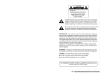
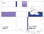
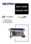
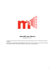
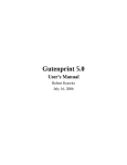
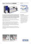
EPSON Programming Guide For 6 Color EPSON Stylus Pro 7000 (PM-7000C) (Level I) EPSON Imaging Technology Center Revision: 1 (Date: 6/20/00) Page: 1 All Rights Reserved. This publication may only be used for the purposes of research and development of products and services enhancing, enabling, or facilitating existing and future products and services bearing the EPSON trademark, and for providing support to those engaging or intending to engage in such activities. All other uses are unauthorized. No part of this publication may be reproduced, stored in any retrieval system, or transmitted in any form or by any means without the prior written permission of Seiko Epson Corporation for any other purpose than the authorized uses. No patent liability is assumed with respect to the use of the information contained within. While every precaution has been taken in the preparation of this information, Seiko Epson Corporation and its affiliates assume no responsibility for errors or omissions. Neither is any liability assumed for damages resulting from the use of the information presented within. EPSON and EPSON ESC/P are registered trademarks and EPSON ESC/P 2 is a trademark of SEIKO EPSON Corporation. Copyright ©2000 by SEIKO EPSON Corporation, Nagano, Japan EPSON Imaging Technology Center Revision: 1 (Date: 6/20/00) Page: 2 TABLE OF CONTENTS: CHAPTER 1: INTRODUCTION ............................................................................................................. 6 1.1 EPSON Stylus Pro 7000 ............................................................................................................................................... 6 CHAPTER 2: PAPER TYPES AND SIZES .................................................................................... 9 2.1 EPSON Paper Types and Sizes for the Stylus Pro 7000.............................................................................................. 9 2.2 Paper Type subject to Path & Page Delay, Cutter Auto OFF.................................................................................. 12 2.3 Paper Weight ............................................................................................................................................................. 12 2.4 Characteristic Information for Each Paper Type ..................................................................................................... 13 CHAPTER 3: PRINTABLE AREAS .................................................................................................. 14 3.1 Printable Area – Stylus Pro 7000 Roll Paper....................................................................................................... 14 3.2 Printable Area – Stylus Pro 7000 Cut Sheet Paper.............................................................................................. 15 CHAPTER 4: Printing Mode...................................................................................................................... 17 4.1 Printing Mode – Stylus Pro 7000............................................................................................................................... 17 4.2 Printing MicroWeave................................................................................................................................................. 18 CHAPTER 5: COMMAND SEQUENCE FLOW .................................................................... 19 5.1 Raster Graphics Mode ............................................................................................................................................... 19 5.2 Command Transfer Sequence.................................................................................................................................... 20 5.3 Print cancel sequence –.............................................................................................................................................. 21 CHAPTER 6: INDIVIDUAL COMMAND SPECIFICATION .................................... 22 6.1 Initialize Printer “ESC @” ........................................................................................................................................ 22 6.2 Select Graphics Mode “ESC (G nL nH m” .............................................................................................................. 23 6.3 Set Unit “ESC (U nL nH p v h mL mH” .................................................................................................................. 24 6.4 Turn Unidirectional Mode On/Off “ESC U n” ........................................................................................................ 26 6.5 Select MicroWeave Print Mode “ESC ( i” ................................................................................................................ 27 6.6 Select Dot Size “ESC ( e nL nH m d” ........................................................................................................................ 28 6.7 Set Page Format “ESC (c nL nH t1 t2 t3 t4 b1 b2 b3 b4” ....................................................................................... 29 6.8 Set Paper Size “ ESC (S nL nH w1 w2 w3 w4 l1 l2 l3 l4” ......................................................................................... 31 EPSON Imaging Technology Center Revision: 1 (Date: 6/20/00) Page: 3 6.9 Set Resolution of Raster image “ESC (D nL nH rL rH v h”..................................................................................... 32 6.10 Set Absolute Vertical Print Position “ESC (V nL nH m1 m2 m3 m4 ”.............................................................. 34 6.11 Set Relative Vertical Print Position “ESC (v nL nH m1 m2 m3 m4”.................................................................. 35 6.12 Set Absolute Horizontal Print Position “ESC ( $ nL nH m1 m2 m3 m4”............................................................ 36 6.13 Set Relative Horizontal Print Position “ESC (/ nL nH m1 m2 m3 m4” .............................................................. 36 6.14 Select Raster Graphics Data “ ESC i r c b nL nH mL mH d1…dk “.................................................................. 38 6.15 New Page (Form Feed) “FF”............................................................................................................................... 40 6.16 Enter Remote Mode Command “ ESC (R ” ........................................................................................................ 41 6.17 Select Mechanism Sequence “SN”....................................................................................................................... 42 6.18 Set Paper Path ”PP” 03H 00H 00H m1 m2 ........................................................................................................ 43 6.19 Set Auto Cutting State “ AC” 02H 00H 00H m1.................................................................................................. 44 6.20 Set Drying Time “DR” 04H 00H 00H m1 m2 m3................................................................................................ 45 6.21 Select Ink Type “IK” 02H 00H 00H m1 .............................................................................................................. 46 6.22 Set Pause After Printing “PZ” 02H 00H 00H m1 .............................................................................................. 47 6.23 Set Vertical Print Page Line Mode “EX” 06H 00H 00H 00H 00H 00H 14H m1 ................................................ 48 6.24 Select Paper Thickness “PH” 02H 00H 00H m1 ................................................................................................. 49 6.25 Terminate Remote Mode “ ESC 00H 00H 00H ”................................................................................................. 50 6.26 Load Default Value “LD 00H 00H”...................................................................................................................... 51 6.27 Paper Size Specification ........................................................................................................................................ 52 CHAPTER 7: SUPPLEMENT .................................................................................................................. 54 7.1 Set Panel and Remote Command............................................................................................................................... 54 7.2 Select Paper Thickness .............................................................................................................................................. 54 7.3 Auto cut ON/OFF ...................................................................................................................................................... 54 7.4 Print Page Line .......................................................................................................................................................... 54 7.5 Paper Saving Function............................................................................................................................................... 55 7.6 Print Cancel Sequence By Users................................................................................................................................ 55 EPSON Imaging Technology Center Revision: 1 (Date: 6/20/00) Page: 4 LIST OF TABLES: Table 1: The EPSON Stylus Pro 7000 Printer Feature Summary...................................................................... 7 Table 2: Stylus Pro 7000 Throughput.................................................................................................................. 8 Table 3: EPSON Paper Types and Sizes for Stylus Pro 7000 ............................................................................. 9 Table 4: Characteristic Information for Each Paper Type – ROLL Paper ........................................... 13 Table 5: Characteristic Information for Each Paper Type – Cut sheet ................................................. 13 Table 6: Printable Area for the EPSON Stylus Pro 7000 – Roll Paper ............................................................ 14 Table 7: Printable Area for the EPSON Stylus Pro 7000 – Cut Sheet.............................................................. 15 Table 8: Printing mode for the EPSON Stylus Pro 7000 .................................................................................. 17 Table 9: Recommended Printer Driver Settings for the EPSON Stylus Pro 7000 Media................................ 18 Table 10: Printer MicroWeave Mode ............................................................................................................... 18 Table 11: Command sequence flow ................................................................................................................... 20 Table 12. Auto Cut/off mode .............................................................................................................................. 54 EPSON Imaging Technology Center Revision: 1 (Date: 6/20/00) Page: 5 This Programming Guide is intended for use in conjunction with the EPSON Standard ESC/P Reference Manual (December 1997) CHAPTER 1: INTRODUCTION This section of the Programming Guide will provide a technical overview of another EPSON’s 6color large format inkjet printer to facilitate driver development. 1.1 EPSON Stylus Pro 7000 The Stylus Pro 7000 is the follow-up to the six-color large format inkjet printer Stylus Pro 9000 introduced by EPSON. The Stylus Pro 7000, a large format printer that is targeted at vertical, rather than the traditional wide horizontal markets that EPSON traditionally markets to. The printer can be used in Image Composition, Print-for-Pay, Service Bureaus, Fine Arts/Pro Photography, Exhibit builder, and more. The printer is going to be sold worldwide as the Stylus Pro 7000 except in Japan, where it is called PM-7000C. The printer first was launched in Japan in December of 1999. Then it was launched in Europe, Asia and the Americas during first/second quarter of 2000. The Stylus Pro 7000 is 24” wide, 1440x720 dpi. It has the same head as Stylus Pro 9000- 320 Nozzles: 64 black and 64 for each color (CMYLcLm). The EPSON Stylus Pro 7000 printer incorporates the following features: • • • • • • • • • • Six individual ink color with Ink quantity detection for each cartridge (100ml) Built in High Quality MicroWeave for square and non-square resolutions Thick media capability up to 1.5 mm 24” paper width (A1) 25-Meter (82 feet) maximum page length Built-in 8-bit bidirectional parallel interface (IEEE-1284) Built-in USB Interface Type B Optional Ethernet I/F card 10Base/100Base High Quality with 1440(H) x 720(V), microdot printing Wide range of paper types This document doesn’t contain information for an individual ISV’s specific driver development, but does contain the new commands associated with the Stylus Pro 7000’s ability to reproduce subtle tone variations. See Table 1 for a quick feature of EPSON Stylus Pro 7000, the first large format printer. EPSON Imaging Technology Center Revision: 1 (Date: 6/20/00) Page: 6 Table 1: The EPSON Stylus Pro 7000 Printer Feature Summary EPSON Stylus Pro 7000 Print Head 64 black nozzles, 320 color nozzles, 64 nozzles x 3 (CMYLcLm). Same head as Stylus Pro 5000. Interface (s) Parallel, USB and Optional Ethernet Printer ESC/P Raster & Language Remote Mode Resolution 1440(h) x 720(v) Max (dpi) Selectable dot Yes size Ink Type **CMYKLcLm Paper type vs. Resolution Matte Paper ****360, 720 (Roll) Photo Quality ****360, 720, Glossy Paper 1440*** (Roll) Photo Quality ****360, 720, Semi Glossy ***1440 Paper (Roll) Photo Quality 720, 1440*** Ink jet Paper (Sheet) Photo Quality 720, 1440*** Glossy Paper (Sheet) Photo Quality 720, 1440*** Glossy Film (Sheet) EPSON Art Board (Sheet) (TBD) * - This printing mode is achieved by the printer driver only. ** - CMYKLcLm refers to: Cyan, Magenta, Yellow, Black, Light Cyan and Light Magenta *** - 1440 (h) x720(v) **** - 720 (h) x360(v) EPSON Imaging Technology Center Revision: 1 (Date: 6/20/00) Page: 7 Table 2: Stylus Pro 7000 Throughput Throughput A1 Print Time Resolution Print Mode 5 Min. 360dpi x 360dpi 8 Min 720dpi x 360dpi 15 Min 720dpi x 720dpi 28 Min 1440dpi x 720dpi Bi-D printing Microweave mode 200cps Bi-D printing Full overlap mode 300cps Bi-D printing Full overlap mode 300cps Bi-D printing 4 pass 300cps EPSON Imaging Technology Center Revision: 1 (Date: 6/20/00) Page: 8 CHAPTER 2: PAPER TYPES AND SIZES 2.1 EPSON Paper Types and Sizes for the Stylus Pro 7000 In addition to the standard plain paper, EPSON provides special paper type in the following sizes: Table 3: EPSON Paper Types and Sizes for Stylus Pro 7000 Stylus Pro 7000 Paper Type/ Subset Plain Paper (Cut sheet) Letter √ US B √ US C √ US D √ A4 √ A3 √ A3+/Super A3/B √ A2 √ A1+ √ A1 √ B5 √ B4 √ B3 √ B2 √ Roll Paper √ (Thickness: 0.1) User-defined √ Paper Size in “inch” Paper Size in “mm” Product Code Number (U.S.) 8.5x11 11x17 17x22 22x34 8.3x11.7 216x279 210x297 297x420 329x483 420x594 24x36 7.2x10.1 594x841 182x257 257x364 364x515 515x728 182-610 x 182-2300 (mm) EPSON Presentation Matte Paper (Roll) (Thickness: 0.2 mm) Presentation 24”x82’ 604mm(24”) x 25m √ Matte Paper EPSON Imaging Technology Center Revision: 1 (Date: 6/20/00) *Refer to Chapter 3: Printable Areas. Page: 9 Table 3: EPSON Paper Types and Sizes for Stylus Pro 7000 - Cont’d Stylus Pro 7000 Paper Type/ Subset Paper Size in “inch” Paper Size in “mm” Product Code Number (U.S.) *EPSON SEMI GLOSS PAPER – HEAVY WEIGHT (Roll) (Thickness: 0.2mm) 24”x82’ 604mm x 25m SEMI GLOSS √ PAPER - HEAVY WEIGHT *EPSON GLOSSY PAPER – HEAVY WEIGHT (Roll) (Thickness: 0.2mm) GLOSSY PAPER 24”x67.9’ 604mm x 20.7m √ GLOSSY PAPER 12.95”x32.81’ 329mm x 10m √ GLOSSY PAPER 8.27”x32.81’ 210mm x 10m √ EPSON Poster Board -Semigloss (Cut Sheet) (Thickness: 1.2mm) Poster Board**20.25”x28.7” 515x728 S041237 √ Semigloss (B2) EPSON Photo Glossy Paper (U.S. only) Photo Glossy Paper EPSON Backlight Film (Roll - U.S. only) Backlight Film Photo Quality Inkjet Paper (Cut Sheet) A3 297x420 √ A3+/Super A3/B 329x483 √ A2 420x594 √ (Thickness: 0.1mm) USC 17x22 S041171 √ A4 210x297 √ USB 11x17 √ Letter 8.5x11 √ Photo Quality Glossy Film (Cut Sheet) A3 297x420 √ A3+/Super A3/B 329x483 √ (Thickness: 0.1) A4 210x297 √ USB 11x17 √ Photo Paper (Cut Sheet) A3 297x420 S041142 √ A3+/Super A3/B 329x483 S041143 √ (Thickness: 0.2) A4 210x297 √ EPSON Imaging Technology Center Revision: 1 (Date: 6/20/00) Page: 10 * These names are for U.S. market only. The Worldwide names for these media “Semigloss Photo Paper- Heavy Weight (Roll)” and “Glossy Photo Paper- Heavy Weight (Roll)” respectively. **The surface of Poster Board – Semigloss is same as Semi Gloss Paper-Heavy Weight. Therefore, with the Poster Board media the “Semi Gloss Paper- Heavy Weight” print mode is used. Note: For Roll Paper - The left, right, top and bottom margins of the Stylus Pro 7000 is 3mm, (42 dots). For Cut Sheet – The top, left, and right margin of the Stylus Pro 7000 is 3mm (42 dots). Except, the bottom margins is 14 mm (198 dots). Cut Sheet – The Minimum User defined paper sizes for the EPSON Stylus Pro 7000 is 7.2” (W) x 7.2” (H) (182mm x 182mm) and the Maximum User defined is 24” (W) x 7.5’(H) (610mmx2300mm) The maximum printing width is 604mm, 8562 dot. (=24” – 3 mm –3 mm) The Minimum and Maximum Printing Width for the Roll Paper is 182mm~610mm. The Maximum Printing Height for the Roll Paper is 25m. The Minimum and Maximum Printing Width for the Cut Sheet paper is 182mm~610mm. The Minimum and Maximum Printing Height for the Cut Sheet paper is 182mm~2300mm. The Default for both the roll paper and the cut sheet for U.S. is letter and for others including the Europe is A4. The paper types supported with each size depend on the market. EPSON Imaging Technology Center Revision: 1 (Date: 6/20/00) Page: 11 2.2 Paper Type subject to Path & Page Delay, Cutter Auto OFF Paper Type Auto Cutter OFF Plain Paper Path Delay Page Delay ms S 0 0 Presentation Matte Paper 0 0 - Glossy Paper-Heavy Weight 0 0 - Semi Gloss Paper-Heavy Weight Photo Quality Ink Jet Paper 0 0 - 0 0 - Photo Paper 0 0 - Photo Quality Glossy Film 0 0 - Poster Board -Semigloss 0 0 OFF - Note: If Cut Sheet is selected, Auto Cutter ON can’t be selected. 2.3 Paper Weight EPSON INK JET MEDIA SPECIFICATION TABLE Basis Weight Thickness Media Product Name (g/m2) Photo Glossy Paper Backlight Film DuPont Commercial Proofing Paper DuPont Commercial Matte Proofing Paper DuPont Publication Proofing Paper Glossy Paper - Heavy Weight Semi Gloss Paper - Heavy Weight Presentation Matte Paper Glossy Film Roll (TBD) Poster Board – Semigloss EPSON Imaging Technology Center Revision: 1 (Date: 6/20/00) (lbs./ream) (mils) 150 155 195 40 41 52 5.5 5 205 55 205 190 180 172 870 ISO Opacity Brightness (ISO %) (%) 95 90 95 9.3 - 80 55 51 48 46 9.3 9.1 8.4 7.9 89 85 80 96 95 90 231 1.2mm 88 100 Page: 12 2.4 Characteristic Information for Each Paper Type Mechanism sequence setting, cutter On/Off information, drying time, and paper thickness are following as characteristic information (TBD) Table 4: Characteristic Information for Each Paper Type – ROLL Paper Paper type 1.1.1. Set mechanism sequence SN 03H 00H 00H 01H <m2> Plain Paper 00H (Default) Matte Paper 00H (Default) Photo Quality Glossy Paper 00H (Default) Photo Quality Semi Glossy Paper 00H (Default) Glossy Film 00H (Default) 1.1.3. Set auto cut AC 02H 00H 00h <m1> 00H(Cutter Off) or 01H(Cutter On or 02H(Print vertical line) 00H(Cutter Off) or 01H(Cutter On or 02H(Print vertical line) 00H(Cutter Off) or 01H(Cutter On or 02H(Print vertical line) 00H(Cutter Off) or 01H(Cutter On or 02H(Print vertical line) 00H(Cutter Off) or 01H(Cutter On or 02H(Print vertical line) DR 04H 00H 00H 00H <m2> <m3> 1.1.5. Set drying time 1.1.9. Set paper thickness PH 02H 00H 00H <m1> 0000H (No drying time) 01H (0.1mm) 0000H (No drying time) 02H (0.2mm) 0000H (No drying time) 02H (0.2mm) 0000H (No drying time) 02H (0.2mm) 0000H (No drying time) 01H (0.1mm) Table 5: Characteristic Information for Each Paper Type – Cut sheet 1.1.1. Set mechanism sequence SN 03H 00H 00H 02H <m2> 1.1.3. Set auto cut AC 02H 00H 00h <m1> Plain Paper 00H (Default) Matte Paper 00H (Default) Photo Quality Glossy Paper 00H (Default) Photo Quality Semi Glossy Paper 00H (Default) Photo Quality Glossy Film 00H (Default) Photo Quality Ink Jet Paper 01H (big PG) 00H(Cutter Off) *n/a for U 00H(Cutter Off) *n/a for U 00H(Cutter Off) *n/a for U 00H(Cutter Off) *n/a for U 00H(Cutter Off) *n/a for U 00H(Cutter Off) *n/a for U Paper type EPSON Imaging Technology Center Revision: 1 (Date: 6/20/00) DR 04H 00H 00H 00H <m2> <m3> 1.1.5. Set drying time 1.1.9. Set paper thickness PH 02H 00H 00H <m1> 0000H (No drying time) 01H (0.1mm) 0000H (No drying time) 02H (0.2mm) 0000H (No drying time) 02H (0.2mm) 0000H (No drying time) 02H (0.2mm) 0000H (No drying time) 01H (0.1mm) 0000H (No drying time) 01H (0.1mm) Page: 13 CHAPTER 3: PRINTABLE AREAS 3.1 Printable Area – Stylus Pro 7000 Roll Paper d a b c d e a b c e f f Table 6: Printable Area for the EPSON Stylus Pro 7000 – Roll Paper Paper type a b c d “Units are in dots where 1 dot = 1/360” Letter US B US C US D A4 A3 Super A3/B A2 A1 B5 B4 B3 B2 User Defined Left Margin 42 42 42 42 42 42 42 42 42 42 42 42 42 42 EPSON Imaging Technology Center Revision: 1 (Date: 6/20/00) Printable Width 2976 3876 6036 7836 2892 4125 4579 5869 8335 2496 3559 5075 7215 Min. 2496Max. 8562 e f Right Margin Top Margin Printable Height Bottom Margin/ 42 42 42 42 42 42 42 42 42 42 42 42 42 42 42 42 42 42 42 42 42 42 42 42 42 42 42 42 3876 6036 7836 12156 4125 5869 6762 8335 11836 3559 5075 7215 10234 Min. 2496Max. 32514 42 42 42 42 42 42 42 42 42 42 42 42 42 42 Page: 14 3.2 Printable Area – Stylus Pro 7000 Cut Sheet Paper d a b c d e a b c e f f Table 7: Printable Area for the EPSON Stylus Pro 7000 – Cut Sheet Paper type a b c d “Units are in dots where 1 dot = 1/360” Letter US B US C US D A4 A3 Super A3/B A2 A1 B5 B4 B3 B2 User Defined e f Left Margin Printable Width Right Margin Top Margin Printable Height Bottom Margin/ 42 42 42 42 42 42 42 42 42 42 42 42 42 42 2976 3876 6036 7836 2892 4125 4579 5869 8335 2496 3559 5075 7215 Min. 2496Max. 8562 42 42 42 42 42 42 42 42 42 42 42 42 42 42 42 42 42 42 42 42 42 42 42 42 42 42 42 42 3720 5880 7680 12000 3969 5713 6606 8179 11680 3403 4919 7059 10078 Min. 2340Max. 32358 198 198 198 198 198 198 198 198 198 198 198 198 198 198 EPSON Imaging Technology Center Revision: 1 (Date: 6/20/00) Page: 15 Notes: Left and top Margins: 42 dots (3mm) for both roll paper and cut sheet. Bottom Margin; 42 dots for roll paper, 198 dots (14mm) for cut sheet. (Unit: 360 dpi) The maximum printing width is 604mm. (= 24 inch - 3 mm- 3 mm) The Minimum and Maximum Printing Width for the Roll Paper is 176mm~604mm. The Maximum Printing Height for the Roll Paper is 25m. The Minimum and Maximum Printing Width for the Cut Sheet paper is 176mm~604mm. The Minimum and Maximum Printing Height for the Cut Sheet paper is 165mm~2283mm. EPSON Imaging Technology Center Revision: 1 (Date: 6/20/00) Page: 16 CHAPTER 4: Printing Mode 4.1 Printing Mode – Stylus Pro 7000 Following table shows ink duty and printing mode for each Media type, Resolution, MicroWeave, Dot Control and Bi-directional ( High Speed) for the EPSON Stylus Pro 7000. These printing modes use the printer MicroWeave. If you do not use the printer MicroWeave, then the command parameters are different. Table 8: Printing mode for the EPSON Stylus Pro 7000 Media type Plain Paper Presentation Matte Paper Glossy PaperHeavy Weight Semi Gloss PaperHeavy Weight Photo Quality Ink Jet Paper Photo Quality Glossy Film Poster Board Semigloss ESC U on/off on/off on/off on/off on/off on/off on/off on/off on/off on/off off off on/off Resolution Setting ESC ( D 360x360 360x360 720x720 720x360 1440x720 720x720 720x360 1440x720 720x720 720x360 1440x720 720x720 1440x720 ESC ( i None FOL FOL FOL 4pass FOL FOL2 4pass FOL FOL2 4pass FOL 4pass 720x720 on/off 720x720 FOL 1440x720 720x720 720x360 on/off on/off on/off 1440x720 720x720 720x360 4pass FOL FOL Input Resolution HxV(dpi) 360x360 360x360 720x720 720x360 1440x720 720x720 720x360 1440x720 720x720 720x360 1440x720 720x720 1440x720 Bi-D M/W Setting Refer to Table 9 for the recommended printer driver settings for the Stylus Pro 7000 media. EPSON Imaging Technology Center Revision: 1 (Date: 6/20/00) Page: 17 Table 9: Recommended Printer Driver Settings for the EPSON Stylus Pro 7000 Media Media Type Printer Driver Mode Plain Paper Plain Paper Presentation Matte Paper Presentation Matte Paper *GLOSSY PAPER-HEAVY WEIGHT Photo Paper *SEMI GLOSS PAPER- HEAVY WEIGHT Semi Gloss Photo Paper Poster Board-Semigloss Semigloss Photo Paper Glossy Film Roll Glossy Film Photo Glossy Paper Photo Quality Glossy Film Backlight Film Photo Quality Glossy Film These names are for U.S. market only. The Worldwide names for these media the “Semigloss Photo Paper- Heavy Weight (Roll)” and the “Glossy Photo Paper- Heavy Weight (Roll)” respectively. 4.2 Printing MicroWeave The printer MicroWeave modes are controlled by Resolution setting command, MW setting command, and Dot control command as follows. Table 10: Printer MicroWeave Mode Input Output Pass Resolution Resolution HxV (dpi) HxV (dpi) MW Setting Dot Control ESC ( D ESC ( i 1 360x360 MW 1 360x360 None 360x360 720x360 2 360x360 FOL 720x720 2 360x360 FOL2 720x360 720x360 1 720x360 MW 2 720x360 FOL 720x720 2 720x360 FOL2 720x720 720x720 1 720x720 MW 2 720x720 FOL 2 720x720 FOL 4 720x720 4pass 1440x720 1440x720 2 1440x720 FOL 4 1440x720 4pass Input Resolution: Data resolution to input to printer Output Resolution: Print resolution ESC ( e Normal 2dot Normal 2dot Normal 2dot Normal 2dot Normal 1dot Normal 1dot Normal 1dot Normal 1dot Normal 1dot Micro Micro Micro Micro 360x360 360x360 EPSON Imaging Technology Center Revision: 1 (Date: 6/20/00) Resolution Setting Page: 18 CHAPTER 5: COMMAND SEQUENCE FLOW 5.1 Raster Graphics Mode The Raster graphics command controls the following two modes. 1) Non-compressed mode Print data are transferred without compression. This is effective especially for photographs and other data, which yield only a low compression ratio. 2) RLL compression mode Print data are compressed using RLL (run-length limited) compression. This is effective for data with repeated patterns, such as graphics and illustrations. EPSON Imaging Technology Center Revision: 1 (Date: 6/20/00) Page: 19 5.2 Command Transfer Sequence The basic commands and command sequence for use with non-compressed mode and RLL compression mode are shown below. Command setting procedure for Non compression mode and Run-length compression mode Table 11: Command sequence flow Forward Setting cycle Document Unit Page Unit Raster Unit 1.Initial Setting Items 1.1 Set remote mode 1.1.1 Set Mechanisim Seq. 1.1.2 Set paper path 1.1.3 Set auto cutting state 1.1.4 Set no paper feed eject 1.1.5 Set drying time 1.1.6 Select ink type 1.1.1.7 Set vertical print page line mode 1.1.8 Select paper thickness 1.2 Terminate remote mode 1.3 Initialize 1.4 Set graphic mode 1.5 Set units 2.Print Control 2.1 Print direction control 2.2 Set micro weaving 2.3 Dot control 3.Set Print Format 3.1 Set page format 3.2 Set paper size 4.4.Set Raster Format 4.1 Set raster resolution 5.Set Vertical Position 5.1 Set vertical position 6.Data Output 6.1 Set horizontal position 6.2 Graphics data Repeat above for each color 7.New Page 7.1 New page 8.Print End 8.1 Graphics mode end 8.2 Load default value Command ESC (R SN PP AC m1=00H, 01H, or 02H AC m1=40H or 41H DR IK EX 06H 00H 00H 00H 00H 00H 14H m1 PH ESC 00H ESC @ ESC ( G ESC ( U ESC U ESC ( i ESC ( e ESC ( c ESC ( S ESC ( D ESC ( v or ESC ( V ESC ( / or ESC ( $ ESC i FF ESC @ ESC (R LD ESC 00H The commands in the above table are basically identical for both modes. The difference between 2 modes are command parameter and data format. Note, items in bold are either new or not included in the ESC/P Reference manual. See individual command sections of this Programming Guide for the information. EPSON Imaging Technology Center Revision: 1 (Date: 6/20/00) Page: 20 “ESC ( R” is an ESC/P2 command to enter the EPSON REMOTE Mode. While in this mode, no ESC/P or ESP/P 2 commands will be recognized by the printer until the “ESC 00H” command is invoked to exit Remote Mode. See the Remote mode section for more information. ESC (/, ESC($ (Set horizontal position command) is recommended to shift to left margin. (To standardize specification: Command to shift left margin has no CR command.) Cautions to set command - The blank of vertical direction should be shifted by Set vertical position command. (Avoid filling blank with NULL image.) - Use printer micro weaving Number of vertical direction dots of data is 1 when data is transmitted with Select raster data command ESC i. ESC i command, mL=1, mH=0 ESC (V, ESC (v command x 6 colors Refer to Chapter 7 for specifications of using commands. 5.3 Print cancel sequence – This is when user cancels printing job. Page Unit Raster Unit 5.Set Vertical Position 5.1 Set vertical position 6.Data Output 6.1 Set horizontal position 6.2 Graphics data Repeat above for each color ESC ( v or ESC ( V ESC ( / or ESC ( $ ESC i 7.Print Cancel ESC @ ESC (R AC 02H 00H 00H 41H ESC 00H FF 7.1 Graphics mode end 7.2 Blank skip eject mode set 7.3 New page 7.4 Load default value ESC (R LD ESC 00H The commands in the above table are basically identical for both non-compression mode and runlength compression mode. The only differences between the 2 modes are command parameter and data format. EPSON Imaging Technology Center Revision: 1 (Date: 6/20/00) Page: 21 CHAPTER 6: INDIVIDUAL COMMAND SPECIFICATION 6.1 Initialize Printer “ESC @” Format: ASCII Hex Decimal ESC 1B 27 @ 40 64 Function: - - The various settings are returned to their initial values. The function of the CAN command is executed. The page management coordinate system and the position management coordinate system are set by taking the origin upon the Y-axis as the present printing position on the Y-axis. The present printing position on the X-axis is set to the origin upon the X-axis. The text mode is selected. Related Commands: Commands related in the direction of applying an effect (Setting) The settings for all commands are returned to their initial states. Commands related in the direction of receiving an effect (Setting) None Commands related in the direction of applying an effect (Operation) None Commands related in the direction of receiving an effect (Operation) None EPSON Imaging Technology Center Revision: 1 (Date: 6/20/00) Page: 22 6.2 Select Graphics Mode “ESC (G nL nH m” Format: ASCII Hex Decimal ESC 1B 27 ( 28 40 G 47 71 nL nL nL nH nH nH m m m Range of Definition: nL=01H, nH=00H m=01H or 31H Function: - Shifts to graphics mode. - If m has any value other than the above, this command is ignored. - Printing of lines up to the present line is started, and the printer waits until the printing is completed. - The various settings are the same as when the power is turned on. - The page management coordinate system and the position management coordinate system are set by taking the printing position in the Y direction at the time of setting as the origin upon the Y-axis. - The printing position in the X direction is set to the origin upon the X-axis. - The MicroWeave print mode selection command is effective. Initial State: The character mode. Related Commands: Commands related in the direction of applying an effect (Setting) The character mode selection made by the ESC @ command is changed. Commands related in the direction of receiving an effect (Setting) The graphics mode is canceled by the ESC @ command. Commands related in the direction of applying an effect (Operation) Only the following commands are valid for Stylus Pro 7000 in Graphics mode: LF ESC (C FF CR ESC (U ESC (V ESC. ESC (r ESC + ESC (v ESC @ ESC H ESC (c ESC $ ESC (i ESC r ESC (S ESC U ESC (e ESC ( / ESC ESC G Commands related in the direction of receiving an effect (Operation) None EPSON Imaging Technology Center Revision: 1 (Date: 6/20/00) Page: 23 6.3 Set Unit “ESC (U nL nH p v h mL mH” Format: ASCII Hex Decimal ESC 1B 27 ( 28 40 U 55 85 nL nL nL nH nH nH p p p v v v h h h mL mL mL mH mH mH Range of Definition: nL=05H, nH=00H p=01H, 02H, 04H, 08H v=01H, 02H, 04H, 08H h=01H, 02H, 04H, 08H mL=A0H, mH=05H Function: - - Set the following standard units in units of P/(mH*256+mL) inch. Page units ESC (c, ESC (C, ESC (S, etc. Set the following standard units in units of V/(mH*256+mL) inch. Vertical position units ESC (v, ESC (V, etc. Set the following standard units in units of H/(mH*256+mL) inch Horizontal position units ESC ($, ESC (/, ESC $, ESC \, etc. mL, mH are elective, but 1440 dpi is recommended. This command is effective only at the time of the graphics mode. - Page management units: 1/360 inch Relative horizontal position setting units: 1/180 inch units Absolute horizontal position setting units: 1/60 inch units Relative vertical position setting units: 1/360 inch units Absolute vertical position setting units: 1/360 inch units - Initial State: Related Commands: Commands related in the direction of applying an effect (Setting) None Commands related in the direction of receiving an effect (Setting) None Commands related in the direction of applying an effect (Operation) The units for the relative horizontal position setting by the ESC\ command is set. The units for the absolute horizontal position setting by the ESC $ command is set. The units for the relative horizontal position setting by the ESC (/ command is set. The units for the absolute horizontal position setting by the ESC ($ command is set. The units for the relative vertical position setting by the ESC (v command is set. The units for the relative vertical position setting by the ESC (V command is set. EPSON Imaging Technology Center Revision: 1 (Date: 6/20/00) Page: 24 The units for the “unit” unit page length specification by the ESC (C command is set. The units for the page format specification by the ESC (c command is set. The units for the paper dimension specification by the ESC (S command is set. Commands related in the direction of an effect (Operation) The initial state is returned to by the ESC @ command. EPSON Imaging Technology Center Revision: 1 (Date: 6/20/00) Page: 25 6.4 Turn Unidirectional Mode On/Off “ESC U n” Format: ASCII Hex Decimal ESC 1B 27 U 55 85 n n n Range of Definition: n=00H, 01H, 02H, 30H, 31H, 32H Function: - The printing direction is selected according to the value of n in the following manner: n=00H or 30H: selects Bi-directional printing n=01H or 31H: selects Unidirectional printing n=02H or 32H: selects automatic printing direction control - If n has any value other than the above, this command is ignored. Initial State: Bi-directional printing Related Commands: Commands related in the direction of applying an effect (Setting) Initialization by the ESC @ command is overridden. Commands related in the direction of receiving an effect (Setting) It is reset to the initial state by the ESC @ command. Commands related in the direction of applying an effect (Operation) None Commands related in the direction of receiving an effect (Operation) None EPSON Imaging Technology Center Revision: 1 (Date: 6/20/00) Page: 26 6.5 Select MicroWeave Print Mode “ESC ( i” Format: ASCII Hex Decimal ESC 1B 27 ( 28 40 i 69 105 none none n 01 00 n 1 0 n Range of Definition: n = 00H, 01H, 30H, 31H, 02H, 32H, 03H, 33H, 04H, 34H Function: - Select /deselect the MicroWeave mode: n=0, 30H: Deselect n=1, 31H: Select simple Micro Weaving n=2, 32H: Select Full-overlap(FOL) n=3, 33H: Select 4pass n=4, 34H: Select FOL2 - The following is combination of settings for Stylus Pro 7000: Density (v x h) 180 x 180 180 x 360 180 x 720 360 x 360 360 x 720 720 x 720 720 x 1440 o Effective None o o o - M/W o o o - FOL o o o o 4Pass o o o FOL2 o o - Invalid None None None M/W M/W M/W FOL - Invalid If invalid combination is set, the setting is invalid. Initial State: Non-MicroWeave mode Related Commands: Commands related in the direction of applying an effect (Setting) The deselect status by the ESC (G command is changed. The deselect status by the ESC @ command is changed. Commands related in the direction of receiving an effect (Setting) The deselect status is set by the ESC (G command. The deselect status is set by the ESC @ command. Command related in the direction of applying an effect (Operation) None Commands related in the direction of receiving an effect (Operation) None EPSON Imaging Technology Center Revision: 1 (Date: 6/20/00) Page: 27 6.6 Select Dot Size “ESC ( e nL nH m d” Format: ASCII Hex Decimal ESC 1B 27 ( 28 40 e 65 101 nL 02 02 nH 00 00 m m m d d d Range of Definition: nL = 02H, nH= 00H m = 00H, d = 00H, 01H, 02H, 03H, 04H Function: - The value of d specifies the Dot Size. d 00H: 01H: dot size 1 02H: dot size 2 03H: dot size 3 Dot Size Default* Micro dot Normal dot (Single) Normal x 2 (Double) * Dot selection Normal (Single or Double) is performed automatically depending upon the chosen resolution. - Dot control is effective regardless of the printing mode and printing density. If the dot size is changed in the middle of the page, the operation is not guaranteed. m is the parameter to extend functions, it is fixed with 0. If n has a value not specified above, this command is ignored. Initial State: Default Related Commands: Commands related in the direction of applying an effect (Setting) None Commands related in the direction of receiving an effect (Setting) The default is specified by the ESC @ command. The default is specified by the ESC (G command. Commands related in the direction of applying an effect (Operation) None Commands related in the direction of receiving an effect (Operation) None EPSON Imaging Technology Center Revision: 1 (Date: 6/20/00) Page: 28 6.7 Set Page Format “ESC (c nL nH t1 t2 t3 t4 b1 b2 b3 b4” Format: ASCII Hex Decimal ESC 1B 27 ( 28 40 c 63 99 nL nL nL nH nH nH t1…… t4 t1…… t4 t1…… t4 b1…... b4 b1…... b4 b1…... b4 Range of Definition: nL=08H, nH=00H 0≤ t1, t2, t3, t4, b1, b2, b3, b4 ≤ 255 (t4x 256x256x256 + t3x 256x256 + t2x256 + t1) < (b4x 246x256x256 + b3 x 256x256 + b2x256 + b1) < = 1FFFFFFFH/1440 inch Function: - - - - Taking as its origin, on the Y-axis sets the position management coordinate system, a position spaced in the positive direction by (t4x256x256x256 + t3x256x256 + t2x256 + t1) x (page management units) inches from the origin on the Y-axis of the page management coordinate system. Further, the bottom margin is set at a position spaced in the positive direction by (b4x256x256 256 + b3 x 256x256 + b2 x256 +b1) x (page management units) inches from the origin on the Y-axis of the position management coordinate system. The printing position in the Y direction is shifted to the origin of the position management coordinate system. At this time, the origin on the X axis is not changed. If the distance from the origin on the Y axis of the position management coordinate system to the bottom margin position is greater than the page length, then this distance from the origin on the Y axis to the bottom margin position is set as new page length. If the paper that is inserted is cut sheet paper, then the distance from the top margin position to the bottom margin position is set as the page length. This command is effective only in the graphics mode. If this command was received right after paper is fed, it is shifted to the top margin position setting. Initial State: - The top margin position is set to 0 inches. The bottom margin position is set to the page length. The page length of the Roll Paper is set to 11 inches. The page length of the Cut Sheet Paper is set to 44 inches. Related Commands: EPSON Imaging Technology Center Revision: 1 (Date: 6/20/00) Page: 29 - - - Commands related in the direction of applying an effect (Setting) The set page length is changed by the ESC (C commands. Commands related in the direction of receiving an affect (Setting) The top margin and the bottom margin are set by the ESC ( C command. The page length and the bottom margin position are returned to their initial states by the ESC @ and the ESC (G commands. Commands related in the direction of applying an effect (Operation) New page processing by the FF command is affected (the amount of movement is changed). New lines generated by the LF command that goes outside of the printable area is affected. Processing by the ESC (v command is affected. Processing by the ESC (V command is affected. Commands related in the direction of receiving an effect (Operation) The page management units are set by the ESC (U command. EPSON Imaging Technology Center Revision: 1 (Date: 6/20/00) Page: 30 6.8 Set Paper Size “ ESC (S nL nH w1 w2 w3 w4 l1 l2 l3 l4” Format: ASCII ESC Hex 1B Dec. 27 ( 28 40 S 53 83 nL nL nL nH nH nH w1.. w1.. w1.. w4 w4 w4 l1 l1 l1 l2 l2 l2 l3 l3 l3 l4 l4 l4 Range of Definition: nL=08H, nH=00H Function: - Set (w4x256x256x256+w3x256x256+w2x256+w1) x (Page Control Units) inches as the X direction paper width (actual width from the left to the right). Set (l4x256x256x256+l3x256x256+l2x256+l1) x (Page Control Units) inches as the Y direction paper length (actual length from the top to the bottom). - The top margin and the bottom margin do not affect the page length. - If the paper size is 0, it will be ignored as not specified. - If it is set right after , or when paper is out, from the top of paper to the bottom of paper is considered to be the paper length. - If it is set not just after paper feeding, and when paper is in, from the setting position to the bottom of paper is considered to be the paper length. - This command can be used only during graphics mode, ESC (G. Initial State: - Related Commands: - Commands related in the direction of applying an effect (Setting) None - Commands related in the direction of receiving an effect (Setting) The page control setting unit is set by the ESC (U command. - Commands related in the direction of applying an effect (Operation) None - Commands related in the direction of receiving an effect (Operation) It reset to initial states by ESC @ and ESC (G commands. EPSON Imaging Technology Center Revision: 1 (Date: 6/20/00) Page: 31 6.9 Set Resolution of Raster image “ESC (D nL nH rL rH v h” Format: ASCII HEX Decimal ESC 1B 27 ( 28 40 D 44 68 nL nL nL nH nH nH rL rL rL rH rH rH v v v h h h Range of Definition: nL=04H, nH=00H 0 < v ≤127 0 < h ≤127 Function: - Set resolution of raster image at (rHx256+rL)DPI. Set raster vertical direction resolution at v/(rH x 256 + rL) DPI Set raster horizontal direction resolution at h/(rH x 256 + rL) DPI This command is effective only for the graphic mode. The following tables are the combination of print density, command, and parameter for Stylus Pro 7000. - MicroWeave Function OFF Print Parameters Note density v/r h/r (V x H) 180x180 1/180 1/180 - Micro Weave Function ON Print Parameters Note density (V x H) v/r h/r 360x360 1/360 1/360 360x720 1/360 1/720 720x720 1/720 1/720 720x1440 1/720 1/1440 Initial State: The resolution for both Raster vertical direction and raster horizontal direction is 360 dpi. EPSON Imaging Technology Center Revision: 1 (Date: 6/20/00) Page: 32 Related Command: Commands related in the direction of applying an effect (Setting) Effect to be processed by ESC i command. Command related in the direction of receiving an effect (Setting) The Resolution setting of Raster image is returned to this initial states by the ESC @ and the ESC (G commands. Command related in the direction of applying an effect (Operation) None Command related in the direction of receiving an effect (Operation) None EPSON Imaging Technology Center Revision: 1 (Date: 6/20/00) Page: 33 6.10 Set Absolute Vertical Print Position “ESC (V nL nH m1 m2 m3 m4 ” Format: ASCII HEX Decimal ESC 1B 27 ( 28 40 V 56 86 nL nL nL nH nH nH m1 m1 m1 m2 m2 m2 m3 m3 m3 m4 m4 m4 Range of Definition: nL=04H, nH=00H 0 <= (m4x256x256x256 +m3x256x256 + m2x256 + m1))x (Absolute vertical position setting units) inch <= 1FFFFFFFH/1440 inch Function: - - Initial State: The printing position in the Y direction is set to a position spaced in the positive direction from the present Y printing position in the Y direction by (m4x256x256x256 + m3x256x256 + m2x256 + m1) x (Absolute vertical position set unit) inches. If the printing position in the Y direction has been set by this command to a non-printable region, then the paper is ejected, the position management coordinate system is set to the next page, and the printing position is reset to the origin of the new position management system. If the printing position in the Y direction has been set by this command to a page other than the current page, then the position management coordinate system is shifted to the printable region upon that page, and the following position management is performed upon the new position management coordinate system. Setting in the negative direction is ignored. This command is effective only for the graphic mode. - Related Commands: Commands related in the direction of applying an effect (Setting) None Commands related in the direction of receiving an effect (Setting) None Commands related in the direction of applying an effect (Operation) None Commands related in the direction of receiving an effect (Operation) The Absolute vertical position setting units are set by the ESC (U command. The non-printable region is set by the ESC (c commands. The absolute vertical position setting units, the non-printable region, and the printing position in the Y direction are reset to their initial states by the ESC @ and ESC (G commands. EPSON Imaging Technology Center Revision: 1 (Date: 6/20/00) Page: 34 6.11 Set Relative Vertical Print Position “ESC (v nL nH m1 m2 m3 m4” Format: ASCII Hex Decimal ESC 1B 27 ( 28 40 v 76 118 nL nL nL nH nH nH m1 m1 m1 m2 m2 m2 m3 m3 m3 m4 m4 m4 Range of Definition: nL=04H, nH=00H 0 ≤ (m4x256x256x256 +m3x256x256 + m2x256 + m1))x(Relative vertical position setting units) inch ≤ 1FFFFFFFH/1440 inch Function: - The printing position in the Y direction is set to a position spaced in the positive direction from the present Y printing position by (m4x256x256x256 + m3x256x256 + m2x256 + m1) x (relative vertical position setting units) inches. - The setting in the negative direction is ignored. - If the printing position in the Y direction has been set by this command to a non-printable region, then the position management coordinate system is set to the next page, and the printing position in the Y direction is reset to the origin upon the Y-axis of the new position management coordinate system. If the printing position in the Y direction has been set by this command to a page other than the current page, then the position management coordinate system is shifted to the printable region upon that page, and the following position management is performed upon the new position management coordinate system. - This command is only effective in graphics mode. Initial State: - Related Commands: Commands related in the direction of applying an effect (Setting) None Commands related in the direction of receiving an effect (Setting) None Commands related in the direction of applying an effect (Operation) None Commands related in the direction of receiving an effect (Operation) The relative vertical position setting units are set by the ESC (U command. The non-printable region is set by the ESC (c commands. The relative vertical position setting units, the non-printable region, and the printing position in the Y direction are reset to their initial states by the ESC @ and ESC (G commands. EPSON Imaging Technology Center Revision: 1 (Date: 6/20/00) Page: 35 6.12 Set Absolute Horizontal Print Position “ESC ( $ nL nH m1 m2 m3 m4” Format: ASCII HEX Decimal ESC 1B 27 ( 28 40 $ 24 36 nL nL nL nH nH nH m1 m1 m1 m2 m2 m2 m3 m3 m3 m4 m4 m4 Range of Definition: nL=04H, nH=00H 0 ≤ (m4x256x256x256 +m3x256x256 + m2x256 + m1))x(Absolute horizontal position setting units) inch ≤ 1FFFFFFFH/1440 inch Function: - The printing position in the X direction is set to a position spaced in the positive direction from the origin on the X axis (left margin position) in the position management coordinate system by (m4 x 256 x 256 x 256 + m3 x 256 x 256 + m2 x 256 + m1) x (absolute horizontal position setting unit) inches. The default value of absolute horizontal position set unit is 1/60 inch unit. - If the left margin position + ( m4 x 256 x 256 x256 + m3 x 256 x 256 + m2 x 256 + m1) x (absolute horizontal position set unit) is higher than the right margin position, this command is ignored. - This Command is effective only at the time of the graphic mode. [Initial State] - Related Commands: Commands related in the direction of applying an effect (Setting) None Commands related in the direction of receiving an effect (Setting) None Commands related in the direction of applying an effect (Operation) None Commands related in the direction of receiving an effect (Operation) ESC I command changes the cardinal point of absolute position set. If ESC Q command is higher than the right margin position, this command is ignored. The absolute horizontal position setting units are set by the ESC (U command. The absolute horizontal position setting units are reset to their initial states by the ESC @ and ESC (G commands. 6.13 Set Relative Horizontal Print Position “ESC (/ nL nH m1 m2 m3 m4” EPSON Imaging Technology Center Revision: 1 (Date: 6/20/00) Page: 36 Format: ASCII HEX Decimal ESC 1B 27 ( 28 40 / 2F 47 nL nL nL nH nH nH m1 m1 m1 m2 m2 m2 m3 m3 m3 m4 m4 m4 Range of Definition: nL=04H, nH=00H 0 <= (m4x256x256x256 +m3x256x256 + m2x256 + m1)) x (relative horizontal print position set unit) inch <= 1FFFFFFFH/1440 inch, or If bit 7 of m4 is 1, this means that a negative value has been set. Function: - The printing position in the X direction is set to a position spaced in the positive direction from current X direction printing position by (m4 x 256 x 256 x 256 + m3 x 256 x 256 + m2 x 256 + m1) x (relative horizontal position set unit) inches. The default value of absolute horizontal position set unit is 1/60 inch unit. - If bit 7 of m4 is 1, this means that a negative value is being designated. The negative value is expressed with 2’s complement. - If the printing position is set by this command to a non-printable region, it is ignored. However, the printing position can be shifted on the right margin position. - This command is effective only for the graphic mode. Initial State: - Related Commands: Commands related in the direction of applying an effect (Setting) None Commands related in the direction of receiving an effect (Setting) None Commands related in the direction of applying an effect (Operation) None Commands related in the direction of receiving an effect (Operation) None EPSON Imaging Technology Center Revision: 1 (Date: 6/20/00) Page: 37 6.14 Select Raster Graphics Data “ ESC i r c b nL nH mL mH d1…dk “ Format: ASCII HEX Decimal ESC 1B 27 i 69 105 r r r c c c b b b nL nL nL nH nH nH mL mL mL mH mH mH d1..dk d1..dk d1..dk Range of Definition: r = 00H, 01H, 02H, 04H, 11H, 12H c = 00H, 01H b = 01H, 02H 0 <= ( nHx256 + nL ) <= 7FFFH 0 <= ( mHx256 + mL ) <= 7FFFH Function: - Select a color for the raster according to the “r” value. r=00H : Black r=01H : Magenta r=02H : Cyan r=04H : Yellow r=11H : Light Magenta r=12H : Light Cyan - Select the raster printing mode according to following parameters; c=00H : Full graphic mode (non-compression mode) c=01H : Run-length encoding compression mode - If r is out of above values, the color selected before input of this command is set. - If c is outside of the above values, the printing mode will be set before input of this command. - The number of bit per pixel is set according to b value. - The support value of b is 01H (Stylus Pro 7000). - If b is out of supporting range, this command is terminated when b is processed. - Actual image pattern of raster format set by following parameters is created. nLnH : The number of horizontal direction bytes nHx256+nL(bytes) nH = INT((( (the number of horizontal direction dots) x (the number of bits per pixel) +7) /8) /256) nL = MOD((( (the number of horizontal direction dots) x (the number bits per pixel) +7) /8) /256) mLmH : The number of vertical direction dots mHx256+mL(dots) k : The number of data = (mHx256+mL)x(nHx256+nL) d : Data - The printing position in the X direction is set to a position spaced in the positive direction from current X direction printing position by (nHx256+nL) x (horizontal direction resolution) inches. EPSON Imaging Technology Center Revision: 1 (Date: 6/20/00) Page: 38 - If the printing position is set by this command to a non-printable region (right margin), the printing position in the X direction is reset to the right margin position The printing position in the Y direction is not changed by this command. If the image data is set to a non-printable region, the data is ignored. This command is effective only for the graphic mode. Initial State: - Related Commands: Commands related in the direction of applying an effect (Setting) None Commands related in the direction of receiving an effect (Setting) The resolution is selected by ESC (D command. It is reset to the initial states by the ESC @ command. Command related in the direction of applying an effect (Operation) None Commands related in the direction of receiving an effect (Operation) None EPSON Imaging Technology Center Revision: 1 (Date: 6/20/00) Page: 39 6.15 New Page (Form Feed) “FF” Format: ASCII Hex Decimal Parameters Range: FF 0C 12 - Function: - - The contents of the print buffer are printed, the position management coordinate system is set to the next page, and the printing position is set to the origin on this new position management coordinate system. The paper is output. With single sheet paper, this command is ignored if no paper is input. Initial State: - Related Commands: Commands related in the direction of applying an affect (Setting) None Commands related in the direction of receiving an affect (Setting) None Commands related in the direction of applying an affect (Operation) None Commands related in the direction of receiving an effect (Operation) The page length is set by the ESC ( c command. The page length and the left margin position are reset to their initial states by the ESC @ and ESC (G commands. EPSON Imaging Technology Center Revision: 1 (Date: 6/20/00) Page: 40 6.16 Enter Remote Mode Command “ ESC (R ” Format: ASCII ESC Hex 1B Dec 27 ( 28 40 R 52 82 08H 08 08 00H 00 00 00H 00 00 REMOTE1 52 45 4D 4F 54 45 31 82 69 77 79 84 69 49 Function: - This command is used to enter Remote Mode from ESC/P or ESC/P 2 mode. Exits current printer controls language and enters Remote Mode. This mode is maintained until the Exit Remote Mode command “ESC 00 00 00” is accepted by the printer. - This command is only valid in text mode. If the printer buffer contains data prior to entering Remote mode, the data will be printed prior to entering Remote Mode. Once in Remote Mode, the printer does not accept ESC/P 2 commands. Note: - EPSON Imaging Technology Center Revision: 1 (Date: 6/20/00) Page: 41 6.17 Select Mechanism Sequence “SN” The printer driver can control the head gap by this SN command. Format: ASCII Hex Dec S 53 83 N 4E 78 03H 03 03 00H 00 00 00H 00 00 m1 m1 m1 m2 m2 m2 Parameters: The following m1 and m2 parameters are each one byte binary values that indicates mechanism sequences. m1 00H 01H 00H 02H-FFH m2 -00H 01H 02H-FHH Description Feed paper sequence setting Default PG Setting Comment Not used for Stylus Pro 7000 Platen gap setting PG High Reserved Reserved Function: - The default environment mechanism sequence is set If parameter m1, m2 are out of range (02H=FFH), this command is ignored and the current setting is maintained. While in the EPSON Remote Mode, ESC/P2 commands are not recognized by the printer until “ESC 00H 00H 00H” is invoked to exit this Mode. Remote Mode commands should be sent prior to sending ESC/P2 commands. This command is only valid in Remote Mode. EPSON Imaging Technology Center Revision: 1 (Date: 6/20/00) Page: 42 6.18 Set Paper Path ”PP” 03H 00H 00H m1 m2 Format: “PP” 03H 00H 00H m1 m2 Parameters: The parameter m1 is one byte binary value, and indicates the paper path: Paper Manual feed Roll paper Reserved m1 02H 03H 04H - FFH The parameter m2 is one byte binary parameter, and indicates the paper path Number. This has no meaning with Stylus Pro 7000 Function - - The paper path default environment is set. If the selected paper path by the panel is different from the paper path specified by this command, due to mismatch paper an error message appears with Stylus Pro 7000. If parameter m1 is out of range (00H, 01H, 04H-FFH), this command is ignored and the current setting is maintained. This command is only valid in remote mode. EPSON Imaging Technology Center Revision: 1 (Date: 6/20/00) Page: 43 6.19 Set Auto Cutting State “ AC” 02H 00H 00H m1 Format: “AC” 02H 00H 00H m1 Parameters: Parameter m1 is a one byte binary value, and indicates the state as follows: Set Auto Cutting Auto Cutting Off Auto Cutting On Horizontal print page line On Blank skip eject mode reset Blank skip eject mode set Reserved m1 00H 01H 02H 40H 41H 03H - FFH Function: - The default environment roll paper auto cutting state is set. If the auto cutting is on, the roll paper is cut automatically at TOF position just after FF command is executed. If the horizontal dot printing is on, it prints horizontal lines at a height of 1 dot at TOF position just after FF command is executed. (for manual cutting) If the sheet is set, or if it is not stopped at TOF position just after FF command is executed, it doesn’t cut paper / print horizontal line even if it’s On. If parameter m1 is out of range, this command is ignored and the existing setting is maintained. This command is only valid in remote mode. Exception: - When the banner mode is set, it executes the LD Command, then the FF Command is processed. EPSON Imaging Technology Center Revision: 1 (Date: 6/20/00) Page: 44 6.20 Set Drying Time “DR” 04H 00H 00H m1 m2 m3 Format: “DR” 04H 00H 00H m1 m2 m3 Parameters: The m1, m2 and m3 are each one byte binary parameters. Parameter m1 indicates the state as follows: Drying Position Per scan Per page Reserved m1 00H 01H 02H - FFH The drying time by the following expression is set by the parameters m2 and m3. If m1=00H(drying per scan), the unit of time is m second. If m1=01H(drying per page), the unit of time is seconds. (Drying Time) = ((m3 x256) + m2) m1=00H: 0 ≤ (Drying Time) ≤ 10000 m seconds m1=01H: 0 ≤ (Drying Time) ≤ 3600 seconds Function: - The default environment drying time is set. Stop on the position unit set by m1 for the time set by m2 and m3. If it is per page, it is waiting for setting time after received FF command. (If the FF command is not received, it doesn’t stop.) If parameter m1, m2, and m3 are out of range, this command is ignored and the existing setting is maintained. This command is only valid in remote mode. Exception: - If the banner mode is set, it processes after the LD command is executed and not after the FF command. EPSON Imaging Technology Center Revision: 1 (Date: 6/20/00) Page: 45 6.21 Select Ink Type “IK” 02H 00H 00H m1 Format: “IK” 02H 00H 00H m1 Parameters: Parameter m1 is one byte binary parameter, and indicates the ink type as follows: Ink Type Dye ink Pigment ink Reserved m1 00H (N/A) 02H - FFH Function: - The default environment ink type is set. If parameter m1 is out of range, this command is ignored and the existing setting is maintained. This command is only valid in remote mode. EPSON Imaging Technology Center Revision: 1 (Date: 6/20/00) Page: 46 6.22 Set Pause After Printing “PZ” 02H 00H 00H m1 Format: “PZ” 02H 00H 00H m1 Parameters: Parameter m1 is one byte binary code, and indicates the state as follows: Set Pause After Printing Off On Reserved m1 00H 01H 02H - FFH Function: - The default pause state after printing is set. If the pause after printing is ON, the printer is stopped at the pause state after the FF command is executed. If the auto cutting is set, it is pausing after cutting / printing horizontal lines. If parameter m1 is out of range, this command is ignored and the existing setting is maintained. This command is only valid in remote mode. Exception: - If the banner mode is set, it processes after the LD command is executed and not after the FF command. EPSON Imaging Technology Center Revision: 1 (Date: 6/20/00) Page: 47 6.23 Set Vertical Print Page Line Mode “EX” 06H 00H 00H 00H 00H 00H 14H m1 Format: “EX” 06H 00H 00H 00H 00H 00H 14H m1 Parameters: Parameter m1 is one byte binary code, and indicates the state as follows: Set Vertical Print Page Line Mode Off On Reserved m1 00H 01H 02H - FFH Function: - - The default environment vertical print page line mode is set. If the paper width is set previously, and the actual paper width is longer than setting, it prints vertical lines at a width of 1 dot on the horizontal position within setting paper width from the top margin position to the bottom position. If the paper width is not set yet, it doesn’t print. If parameter m1 is out of range, this command is ignored and the existing setting is maintained. This command is only valid in remote mode. EPSON Imaging Technology Center Revision: 1 (Date: 6/20/00) Page: 48 6.24 Select Paper Thickness “PH” 02H 00H 00H m1 Format: “PH” 02H 00H 00H m1 Parameters: Parameter m1 is one byte binary code, and indicates the state as follows: Select Paper Thickness Thickness 0.0 mm Thickness 0.1 mm Thickness 0.2 mm Thickness 0.3 mm Thickness 0.4 mm Thickness 0.5 mm Thickness 0.6 mm Thickness 0.7 mm Thickness 0.8 mm Thickness 0.9 mm Thickness 1.0 mm Thickness 1.1 mm Thickness 1.2 mm Thickness 1.3 mm Thickness 1.4 mm Thickness 1.5 mm Thickness 1.6 mm Reserved m1 00H 01H 02H 03H 04H 05H 06H 07H 08H 09H 0AH 0BH 0CH 0DH 0EH 0FH 10H 11H - FFH Function: - The default environment paper thickness is set. If parameter m1 is out of range, this command is ignored and the existing setting is maintained. This command is only valid in remote mode. Note: The setting of platen gap isn’t changed, even if the thickness is set less than 0.5mm by this command. However, if the thickness is set more than 0.6mm, the platen gap high is set forcibly. EPSON Imaging Technology Center Revision: 1 (Date: 6/20/00) Page: 49 6.25 Terminate Remote Mode “ ESC 00H 00H 00H ” Format: ESC 00H 00H 00H Function: - The following procedures are executed: The default environment is copied to the current environment. If interface related items have been changed, the interface related state and settings are changed. Software initialization is executed (If in ESC/P mode, initialization by ESC @. In other printer languages, initialization corresponding to ESC @.) The remote mode is terminated, and the mode is changed to the selected printer language. This command is only valid in remote mode. EPSON Imaging Technology Center Revision: 1 (Date: 6/20/00) Page: 50 6.26 Load Default Value “LD 00H 00H” Format: LD 00H 00H Function: - - - The following procedures are executed: The power on default environment memorized in NVRAM is loaded to default environment. NVRAM indicates EEPROM, DIP-SW, and ROM. The power on default environment is read from the appointed NVRAM with each setting item, and the default environment is loaded. However, settings by following commands are not changed by this command. (not loading) SM command (set the status transmitting mode) Baud rate setting value for the MAC serial by the BR command (set baud rate) is not initialized. (The built-in EIA-232D serial interface intended to be initialized.) This command is only valid in remote mode. EPSON Imaging Technology Center Revision: 1 (Date: 6/20/00) Page: 51 6.27 Paper Size Specification The region on the paper is separated for 2 regions, the printable region and the nonprintable region. These regions are defined as following; The printable region is the region that can be set for the printing position, and the region surrounded by the left margin position setting, the right margin position setting, the top margin position setting, and the bottom margin position setting. The non-printable region is the region that cannot be set for the printing position except for the right margin position, and the region out of the printable region on the paper. Each margins for the printable region is defined as following; The left margin is the non-printable region width added on the left side of the printable region. The left margin position indicating the border of the margin is set on the X- axis. The left margin position is included in the printable region. The right margin is the non-printable region width added on the right side of the printable region. The right margin position indicating the border of the margin is set on the X-axis. The right margin position is included in the non-printable region. However, the printing position on the right margin position can be set. The top margin is the non-printable region height added on the top of the printable region. The top margin position indicating the border of the margin is set on the Y-axis. The top margin position is included in the printable region. The bottom margin is the non- printable region height added under the bottom of the printable region. The bottom margin position indicating the border of the margin is set on the Y-axis. The bottom margin position is included in the non-printable region. The page management coordinate system is the standard to set each margin positions is same as the position management coordinate system except definition of the origin. The coordinate system to manage printable region set in the page management coordinate system is the position management coordinate system. The page management coordinate system is set per page. The origin of the page management coordinate system is defined as following; The origin on the X-axis is set on the smallest printing position. The smallest printing position is the printing position at the left end that can be set on the paper physically. The smallest printing position depends on the horizontal position of paper at the time of input. EPSON Imaging Technology Center Revision: 1 (Date: 6/20/00) Page: 52 The origin of the Y-axis is the top end of the paper for the page 1 just after feeding paper. The origin of the Y-axis after the page two is the position added page length to the origin of the page management coordinate system in the last page. In the case of cutting sheet, the top of the paper is the origin all the time, because only 1 page can be set. The page and the page length are defined as following; The page is the Y direction unit region including one printable region in it. If it’s the cutting sheet, only one page can be set on the paper. If it’s the roll paper, plural pages can be set on the paper. The page length is the Y direction length on the page. If it’s the cutting sheet, the page length is the Y direction printing region length from the top margin position almost to the bottom margin position. If it’s the roll paper, the page length is the length from the top margin position on the current page to the top margin position on the next page. The printing region of cutting sheet EPSON Imaging Technology Center Revision: 1 (Date: 6/20/00) Page: 53 CHAPTER 7: SUPPLEMENT 7.1 Set Panel and Remote Command This printer has a display operation panel, and each setting can be set by the panel or by the remote commands. The following are the setting by the panel and by the remote commands: - The setting by the panel is saved as the default value of the printer. - The setting value of remote commands is used for items to set by the driver with remote commands. - The default value of the printer is used for items not to set by the driver. - The default value of the printer is loaded by LD commands (remote commands), and the setting by remote commands is cleared. - The driver sets the LD command and returns to the default value of the printer after finishing job to clear the setting by the remote mode. 7.2 Select Paper Thickness The driver sets the paper thickness to the printer by the paper thickness setting command. The printer enhances the print quality using this thickness as data to calculate the gap of the head - paper surface with each mode. See Chapter 2 7.3 Auto cut ON/OFF This function automatically cuts the roll paper with a cutter after the new page. - If the sheet is selected, the selection of the auto cut is invalid. - The printer operation by the setting of the auto cut depends on the combination of the print page line function. - The default setting of the auto cut is ON. Table 12. Auto Cut/off mode Auto Cut Page Line Command Command (Vertical Line) 00H 00H 00H 01H 01H 00H 01H 01H 02H 00H 02H 01H 7.4 Printer Operation Nothing Print vertical lines Auto Cut Print vertical lines and auto cut Print horizontal line Print Page Line (vertical line, horizontal line) Print Page Line EPSON Imaging Technology Center Revision: 1 (Date: 6/20/00) Page: 54 The function to print page line of paper size position on the right side and at the bottom of the paper. - If the sheet is selected, the selection of the print page line is invalid. - The operation depends on the combination of auto cut On/Off. (See last paragraph) - The default setting of the print page line is Off. - The function is available only for printer MicroWeave Mode. 7.5 Paper Saving Function When paper saving function is selected, the printer follows auto cut setting command (cuts automatically, prints horizontal lines, and waits) after feeding paper for the bottom margin at the position received FF (new page) command. As a result, it can save paper if the image data has space at the end. When paper saving function is not selected and the printer receives FF command, it follows auto cut setting command after feeding paper to the position defined with paper size setting command. Refer to “AC” command. 7.6 Print Cancel Sequence By Users When users cancel during printing with the driver, the driver cancels printing to avoid wasting paper with print cancel sequence. When the printer receives a print cancel sequence, it follows auto cut setting command (cuts automatically, prints horizontal lines, and waits) without paper feeding. Stylus Pro 9000 does not follow this command. However, it works with the same sequence although it leaves print data a few mm of the roll paper. Stylus Pro 9000 can avoid leaving print data with print cancel command after transmitting a few mm set vertical position (ESC ( V, ESC (v ) command. Refer to command sequence flow. EPSON Imaging Technology Center Revision: 1 (Date: 6/20/00) Page: 55